EP3038960B1 - Transfervorrichtung mit einer linearmotor-antriebsvorrichtung und federgelagerten abstützelementen - Google Patents
Transfervorrichtung mit einer linearmotor-antriebsvorrichtung und federgelagerten abstützelementen Download PDFInfo
- Publication number
- EP3038960B1 EP3038960B1 EP14744543.1A EP14744543A EP3038960B1 EP 3038960 B1 EP3038960 B1 EP 3038960B1 EP 14744543 A EP14744543 A EP 14744543A EP 3038960 B1 EP3038960 B1 EP 3038960B1
- Authority
- EP
- European Patent Office
- Prior art keywords
- transfer device
- movable element
- elements
- support elements
- angle
- Prior art date
- Legal status (The legal status is an assumption and is not a legal conclusion. Google has not performed a legal analysis and makes no representation as to the accuracy of the status listed.)
- Active
Links
Images






Classifications
-
- B—PERFORMING OPERATIONS; TRANSPORTING
- B65—CONVEYING; PACKING; STORING; HANDLING THIN OR FILAMENTARY MATERIAL
- B65G—TRANSPORT OR STORAGE DEVICES, e.g. CONVEYORS FOR LOADING OR TIPPING, SHOP CONVEYOR SYSTEMS OR PNEUMATIC TUBE CONVEYORS
- B65G54/00—Non-mechanical conveyors not otherwise provided for
- B65G54/02—Non-mechanical conveyors not otherwise provided for electrostatic, electric, or magnetic
Definitions
- the present invention relates to a transfer device, in particular for a product transport, for example a product transport to a packaging machine.
- Transfer systems are known in different configurations.
- the DE 10 2011 003 178 A1 discloses, for example, a transfer system in which a movable conveyor element is movable on a stationary, circumferential track by means of a linear motor drive device. This device has proven itself in principle, however, a slip between the movable conveyor element and the running rail can occur when cornering. Also, in curves, in particular increased wear on the conveyor elements and / or the running rail can occur.
- a transport device is known, which has an articulated conveying element.
- the articulated conveyor element By means of the articulated conveyor element, in particular, the problems occurring during cornering can be solved.
- the articulated conveyor elements are relatively expensive and expensive to manufacture. It would therefore be desirable to have a simply constructed transfer system, which in particular has no signs of wear, even in curves.
- a transfer device according to the preamble of claim 1 is known.
- the transfer device according to the invention with the features of claim 1 has the advantage that even when cornering both on a movable element as well as on a fixed rail significantly less wear and tear occur.
- very tight curves and also countercurves can be provided by means of the running rail, without resulting in excessive sliding or sliding of the movable element.
- the movable element has support elements. The support elements can be brought into contact with the running rail, preferably with running surfaces provided on the running rail.
- At least one of the support elements on a contact surface which are arranged at an angle not equal to 90 ° to a vertical axis and a transverse axis of the movable member.
- contact surfaces of the support elements are arranged at an angle not equal to a right angle to a vertical axis and transverse axis of the movable member, whereby the undesirable slipping or the like can be minimized even when cornering.
- Corresponding to the angle of the contact regions of the support elements and the running surfaces are arranged on the running rail.
- the contact areas of the support elements may be line regions, for example, if the support elements are rollers, or surface areas, for example, if the support elements are sliding elements.
- the support elements are resiliently mounted.
- the resilient mounting provides improved smoothness of the movable member on the track rail. Furthermore, the resiliently arranged support elements can pass better curves, the resilient support elements in particular allow faster cornering. If necessary, the supporting elements spring in case of strong contact with the running rail and thereby avoid undesired wear. This leads to a power minimization.
- the movable element is formed integrally.
- the element can also be formed unevengliedrig.
- the angle of the contact region to a vertical axis and transverse axis is in a range of 30 ° to 60 °, preferably approximately 45 °.
- the angle of the contact region to a vertical axis and transverse axis is in a range of 30 ° to 60 °, preferably approximately 45 °.
- all contact areas of the support elements are arranged at an angle not equal to 90 ° to a vertical axis and transverse axis. This avoids that individual, not inventively arranged support elements may slide when cornering and thus wear or a wear or the like occurs.
- the support elements are preferably provided as rollers and / or sliding elements and / or levitation elements, i.e., free-floating elements.
- At least two support elements are provided, wherein the two support elements are arranged at different angles not equal to 90 ° to a vertical axis and transverse axis.
- the transfer device comprises a support frame with an opening, so that an open, not circumferentially closed, support frame is provided.
- the support frame is formed of a composite material with an outer shell and a core, wherein the support frame has damping properties.
- the support frame has damping properties.
- the material of the core is aluminum and the shell of the support frame is made of a carbon fiber reinforced plastic.
- the open side of the support frame is preferably on a side facing the running rail.
- the movable element on the running track e.g. sit or hang on this.
- the shape of the open support frame is preferably corresponding to an inverted U or V, or a T, or an X, or a Y, or a slotted O.
- the movable element is formed symmetrically to the vertical axis. More preferably, permanent magnets are arranged on the movable element, which are arranged on the support frame on a side facing the running rail. The permanent magnets are part of the linear motor drive device, wherein in the running rail a Bestrombare coil is arranged. The permanent magnets are preferably arranged on the support frame in the region of the opening.
- a pivot point of the movable element is preferably arranged in the region of the permanent magnets.
- the permanent magnets are preferably arranged by means of holders or the like on the support frame of the movable element. More preferably, the support elements of the movable element are arranged by means of holders on the support frame. As a result, by selecting different holders, a standard carrier frame can be used and the different holders each allow a corresponding adaptation to different rails.
- the holders are preferably provided interchangeable.
- the linear motor drive device comprises a plurality of drives.
- the plurality of drives is preferably arranged parallel to each other, alternatively, the plurality of drives are arranged at an angle to each other.
- the running rail comprises a switch.
- the switch is preferably designed as a linear switch, which is changed by parallel displacement of a track piece from a first track to a second track.
- the track rail comprises a rotary switch, wherein a track piece is rotatably arranged and is aligned by rotation of a first track to a second track.
- FIGS. 1 and 2 a transfer device 1 according to a preferred embodiment of the invention described in detail.
- the transfer device 1 comprises at least one movable element 2, which is movable on a running rail 3.
- the running rail 3 may be a circumferentially closed running rail or alternatively also be a linear running rail.
- a plurality of movable elements 2 are arranged on the running rail 3, which are each individually controllable.
- Such transfer devices are used, for example, for supplying products to / and for discharging products from machines, in particular packaging machines.
- the transfer device 1 further comprises a linear motor drive device 4, which comprises a coil 40 integrated in the stationary running rail 3 and permanent magnets 41, wherein the permanent magnets 41 are arranged on the movable element 2.
- a linear motor drive device 4 which comprises a coil 40 integrated in the stationary running rail 3 and permanent magnets 41, wherein the permanent magnets 41 are arranged on the movable element 2.
- the movable element comprises an open support frame 8.
- the support frame 8 comprises a core 9 and an inner shell 10 and an outer shell 11.
- the core 9 is preferably made of aluminum and the two shells are preferably made of a carbon composite material.
- the support frame 8 is in this case open at a lower end and has an upside down, substantially U-shape in cross section. As a result, the movable element 2 sits on the running rail 3.
- the permanent magnets 41 are arranged at the opening of the support frame 8.
- the movable element 2 further comprises supporting elements 5.
- the movable element comprises exactly two supporting elements.
- the support elements of this embodiment each comprise a shaft 50, at the free end of each roller 51 is arranged.
- the rollers 51 have running surfaces 52 on their outer periphery.
- the support elements 5 are fixed by means of first holders 6 on the support frame 8 of the movable element (see FIG. 2 ).
- the movable element 2 also has a vertical axis H and a transverse axis Q.
- the vertical axis H is perpendicular to the transverse axis Q.
- a contact area of the support element 5 is thus provided by the running surface 52 of the rollers 51.
- the contact line lies in a plane E, which is arranged at an angle ⁇ not equal to 90 ° to the vertical axis H and an angle ⁇ not equal to 90 ° to the transverse axis Q.
- the two support elements 5 are each arranged at the same angle ⁇ and ⁇ to the vertical axis H and the transverse axis Q. It should be noted that alternatively, however, the two support elements may be arranged at different angles, but angles of 0 ° or 90 ° are excluded according to the invention. Particularly preferred is the angle ⁇ and the angle ⁇ in a range of 30 ° to 60 °, in particular at about 45 °.
- the movable element 2 has a plurality of support elements 5
- individual support elements 5 can also be arranged at different angles to the transverse axis Q and to the vertical axis H.
- some of the support members may be arranged at equal angles to a plurality of support members.
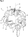
- FIG. 3 shows a second embodiment in which the movable element 2 has exactly six roles as support elements.
- four rollers are arranged at an angle not equal to 90 ° to the vertical axis H and at an angle not equal to 90 ° to the transverse axis Q.
- Two rollers are arranged at the transition region of the U-shaped support frame 8.
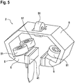
- FIGS. 5 to 7 show a fourth embodiment of the invention.
- the open support frame 8 is formed angular.
- four support elements 5 are provided in the form of rollers 51.
- Three rollers 51 are arranged at an angle not equal to 90 ° to the vertical axis H and not equal to 90 ° to the transverse axis Q.
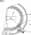
- FIG. 7 shows a cornering of the movable element 2.
- the permanent magnets 41 are aligned to a center of curvature M.
- FIGS. 8 and 9 show a fifth embodiment of the invention, which substantially the second embodiment of FIG. 3 equivalent.
- the supporting elements 5 are provided in the form of sliding elements 61.
- the sliding elements 61 slide on the running track 3. Overall, six sliding elements 61 are provided.
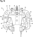
- FIG. 10 shows a sixth embodiment of the invention, in which the support elements 5 are provided in the form of levitation elements 71. How out FIG. 10 it can be seen, ten floating elements 71 are also provided.
- the arrangement of the levitation elements 71 corresponds to the arrangement of the sliding elements in the FIGS. 8 and 9 or the rollers 51 in FIG. 3 , The floating elements thus prevent contact of the running rail 3, so that no wear is present.
- the levitation elements 71 are designed such that even with a contact no damage to the floating elements or the running rail takes place.
- the levitation can be realized for example by magnetic repulsion.
Landscapes
- Linear Motors (AREA)
- Non-Mechanical Conveyors (AREA)
Description
- Die vorliegende Erfindung betrifft eine Transfervorrichtung, insbesondere für einen Produkttransport, beispielsweise einen Produkttransport zu einer Verpackungsmaschine.
Transfersysteme sind in unterschiedlichen Ausgestaltungen bekannt. DieDE 10 2011 003 178 A1 offenbart beispielsweise ein Transfersystem, bei dem ein bewegbares Förderelement auf einer ortsfesten, umlaufenden Laufschiene mittels einer Linearmotor-Antriebsvorrichtung bewegbar ist. Diese Vorrichtung hat sich grundsätzlich bewährt, allerdings können bei Kurvenfahrten ein Schlupf zwischen dem bewegbaren Förderelement und der Laufschiene auftreten. Auch können bei Kurven insbesondere erhöhte Abnutzungen an den Förderelementen und/oder der Laufschiene auftreten. Weiterhin ist aus derDE 10 2010 027 925 A1 eine Transportvorrichtung bekannt, welche ein gelenkiges Förderelement aufweist. Mittels des gelenkigen Förderelements können insbesondere die bei Kurvenfahrten auftretenden Probleme gelöst werden. Allerdings sind die gelenkigen Förderelemente relativ teuer und aufwändig in der Herstellung. Es wäre daher wünschenswert, ein einfach aufgebautes Transfersystem zu haben, welches insbesondere auch bei Kurven keine Abnutzungserscheinungen aufweist. Weiterhin ist aus derWO 2012/084648 A1 ist eine Transfer-Vorrichtung gemäß dem Oberbegriff des Anspruchs 1 bekannt. - Die erfindungsgemäße Transfervorrichtung mit den Merkmalen des Anspruchs 1 weist demgegenüber den Vorteil auf, dass auch bei Kurvenfahrten sowohl an einem bewegbaren Element als auch an einer feststehenden Laufschiene deutlich geringere Abnutzungserscheinungen auftreten. Erfindungsgemäß können insbesondere auch sehr enge Kurven und auch Gegenkurven mittels der Laufschiene vorgesehen sein, ohne dass es hierbei zu einem übermäßigen Gleiten oder Rutschen des bewegbaren Elements kommt. Dies wird erfindungsgemäß dadurch erreicht, dass die Transfervorrichtung ein bewegbares Element, eine feststehende Laufschiene und eine Linearmotor-Antriebsvorrichtung zum Antreiben des bewegbaren Elements aufweist. Das bewegbare Element weist Abstützelemente auf. Die Abstützelemente sind mit der Laufschiene in Kontakt bringbar, vorzugsweise mit an der Laufschiene vorgesehenen Laufflächen. Dabei weist wenigstens eines der Abstützelemente eine Kontaktfläche auf, welche in einem Winkel ungleich 90° zu einer Hochachse und einer Querachse des bewegbaren Elements angeordnet sind. Erfindungsgemäß sind somit Kontaktflächen der Abstützelemente in einem Winkel ungleich einem rechten Winkel zu einer Hochachse und Querachse des bewegbaren Elements angeordnet, wodurch auch bei Kurvenfahrten das unerwünschte Rutschen oder Schlupf oder dergleichen minimiert werden kann. Entsprechend dem Winkel der Kontaktbereiche der Abstützelemente sind auch die Laufflächen an der Laufschiene angeordnet. Die Kontaktbereiche der Abstützelemente können dabei Linienbereiche sein, z.B., wenn die Abstützelemente Rollen sind, oder Flächenbereiche, z.B., wenn die Abstützelemente Gleitelemente sind. Weiter sind die Abstützelemente federnd gelagert. Die federnde Lagerung stellt eine verbesserte Laufruhe des bewegbaren Elements auf der Laufschiene bereit. Ferner können die federnd angeordneten Abstützelemente besser Kurven durchfahren, wobei die federnden Abstützelemente insbesondere eine schnellere Kurvenfahrt erlauben. Gegebenenfalls federn die Abstützelemente nämlich bei einem starken Kontakt mit der Laufschiene ein und vermeiden dadurch einen unerwünschten Verschleiß. Dies führt zu einer Kraftminimierung.
- Die Unteransprüche zeigen bevorzugte Weiterbildungen der Erfindung.
- Bevorzugt ist das bewegbare Element eingliedrig ausgebildet. Das Element kann auch mehrgliedrig ausgebildet sein.
- Vorzugsweise ist der Winkel des Kontaktbereichs zu einer Hochachse und Querachse in einem Bereich von 30° bis 60°, vorzugsweise ungefähr 45°. Hierdurch können auch sehr enge Kurven und Gegenkurven ohne Rutschen durchfahren werden.
- Besonders bevorzugt sind alle Kontaktbereiche der Abstützelemente in einem Winkel ungleich 90° zu einer Hochachse und Querachse angeordnet. Dadurch wird vermieden, dass einzelne, nicht erfindungsgemäß angeordnete Abstützelemente eventuell bei einer Kurvenfahrt gleiten und somit eine Abnutzung oder ein Verschleiß oder dergleichen auftritt.
- Die Abstützelemente sind vorzugsweise als Rollen und/oder Gleitelemente und/oder Levitationselemente, d.h., frei schwebende Elemente, vorgesehen.
- Weiter bevorzugt sind wenigstens zwei Abstützelemente vorgesehen, wobei die beiden Abstützelemente in unterschiedlichen Winkeln ungleich 90° zu einer Hochachse und Querachse angeordnet sind.
- Vorzugsweise umfasst die Transfervorrichtung einen Trägerrahmen mit einer Öffnung, so dass ein offener, nicht umlaufend geschlossener, Trägerrahmen vorgesehen ist.
- Besonders bevorzugt ist der Trägerrahmen aus einem Verbundmaterial mit einer äußeren Hülle und einem Kern ausgebildet, wobei der Trägerrahmen dämpfende Eigenschaften aufweist. Insbesondere weist der Trägerrahmen durch Wahl des Materials des Kerns dämpfende Eigenschaften auf. Beispielsweise ist das Material des Kerns Aluminium und die Hülle des Trägerrahmens ist aus einem Kohlenstofffaser-verstärkten Kunststoff.
- Weiter bevorzugt ist die offene Seite des Trägerrahmens vorzugsweise an einer zur Laufschiene gerichteten Seite. Dadurch kann das bewegbare Element auf der Laufschiene z.B. aufsitzen oder an dieser hängen. Die Form des offenen Trägerrahmens ist vorzugsweise entsprechend einem umgekehrt angeordneten U oder V, oder einem T, oder einem X, oder einem Y, oder einem geschlitzten O.
- Weiter bevorzugt ist das bewegbare Element symmetrisch zur Hochachse ausgebildet. Weiter bevorzugt sind am bewegbaren Element Permanentmagnete angeordnet, welche am Trägerrahmen an einer zur Laufschiene gerichteten Seite angeordnet sind. Die Permanentmagnete sind dabei Teil der Linearmotor-Antriebsvorrichtung, wobei in der Laufschiene eine bestrombare Spule angeordnet ist. Die Permanentmagnete sind vorzugsweise am Trägerrahmen im Bereich der Öffnung angeordnet.
- Für einen besonders ruhigen Lauf des bewegbaren Elements ist vorzugsweise ein Drehpunkt des bewegbaren Elements im Bereich der Permanentmagnete angeordnet.
- Die Permanentmagnete sind vorzugsweise mittels Haltern oder dergleichen an dem Trägerrahmen des bewegbaren Elements angeordnet. Weiter bevorzugt sind auch die Abstützelemente des bewegbaren Elements mittels Haltern am Trägerrahmen angeordnet. Hierdurch kann durch Auswahl verschiedener Halter ein Standard-Trägerrahmen verwendet werden und die verschiedenen Halter jeweils eine entsprechende Anpassung an unterschiedliche Laufschienen ermöglichen. Die Halter sind bevorzugt austauschbar vorgesehen.
- Besonders bevorzugt umfasst die Linearmotor-Antriebsvorrichtung mehrere Antriebe. Die Vielzahl der Antriebe ist vorzugsweise parallel zueinander angeordnet, alternativ sind die Vielzahl der Antriebe winklig zueinander angeordnet. Weiter bevorzugt umfasst die Laufschiene eine Weiche. Die Weiche ist vorzugweise als Linear-Weiche ausgebildet, welche durch Parallelverschieben eines Laufschienenstücks von einer ersten Laufschiene auf eine zweite Laufschiene gewechselt wird. Alternativ umfasst die Laufschiene eine Rotations-Weiche, wobei ein Laufschienenstück drehbar angeordnet ist und durch Rotation von einer ersten Laufschiene auf eine zweite Laufschiene ausgerichtet wird.
- Nachfolgend werden bevorzugte Ausführungsbeispiele der Erfindung unter Bezugnahme auf die begleitende Zeichnung im Detail beschrieben. In der Zeichnung ist:
- Figur 1
- eine schematische, teilweise geschnittene Ansicht einer Transfervorrichtung gemäß einem Ausführungsbeispiel der Erfindung,
- Figur 2
- eine schematische, perspektivische Ansicht eines bewegbaren Elements der Transfervorrichtung von
Figur 1 , und - Figuren 3 bis 10
- weitere bevorzugte Ausführungsbeispiele der Erfindung.
- Nachfolgend wird unter Bezugnahme auf die
Figuren 1 und2 eine Transfervorrichtung 1 gemäß einem bevorzugten Ausführungsbeispiel der Erfindung im Detail beschrieben. - Wie aus
Figur 1 ersichtlich ist, umfasst die erfindungsgemäße Transfervorrichtung 1 wenigstens ein bewegbares Element 2, welches auf einer Laufschiene 3 bewegbar ist. Die Laufschiene 3 kann eine umlaufend geschlossene Laufschiene sein oder alternativ auch eine linienförmige Laufschiene sein. Vorzugsweise sind eine Vielzahl von bewegbaren Elementen 2 auf der Laufschiene 3 angeordnet, welche jeweils individuell ansteuerbar sind. Derartige Transfervorrichtungen werden beispielsweise beim Zuführen von Produkten zu/und beim Abführen von Produkten von Maschinen, insbesondere Verpackungsmaschinen, verwendet. - Die Transfervorrichtung 1 umfasst ferner eine Linearmotor-Antriebsvorrichtung 4, welche eine in die feststehende Laufschiene 3 integrierte Spule 40 sowie Permanentmagnete 41 umfasst, wobei die Permanentmagnete 41 am bewegbaren Element 2 angeordnet sind.
- An der Laufschiene 3 sind ferner Laufflächen 30, 31 vorgesehen.
- Weiterhin umfasst das bewegbare Element einen offenen Trägerrahmen 8. Der Trägerrahmen 8 umfasst einen Kern 9 sowie eine innere Hülle 10 und eine äußere Hülle 11. Der Kern 9 ist vorzugsweise aus Aluminium hergestellt und die beiden Hüllen sind vorzugsweise aus einem Kohlenstoffverbundwerkstoff hergestellt. Der Trägerrahmen 8 ist hierbei an einem unteren Ende offen und weist im Querschnitt eine auf dem Kopf stehende, im Wesentlichen U-Form auf. Dadurch sitzt das bewegbare Element 2 auf der Laufschiene 3 auf.
- Wie aus
Figur 1 ersichtlich ist, sind an der Öffnung des Trägerrahmens 8 die Permanentmagnete 41 angeordnet. - Das bewegbare Element 2 umfasst ferner Abstützelemente 5. In diesem Ausführungsbeispiel umfasst das bewegbare Element genau zwei Abstützelemente. Die Abstützelemente dieses Ausführungsbeispiels umfassen jeweils eine Welle 50, an deren freiem Ende jeweils eine Rolle 51 angeordnet ist. Die Rollen 51 weisen an ihrem äußeren Umfang Laufflächen 52 auf. Die Abstützelemente 5 sind mittels ersten Haltern 6 am Trägerrahmen 8 des bewegbaren Elements befestigt (vergleiche
Figur 2 ). - Das bewegbare Element 2 weist ferner eine Hochachse H und eine Querachse Q auf. Die Hochachse H ist dabei senkrecht zur Querachse Q.
- Ein Kontaktbereich des Abstützelements 5 wird somit durch die Lauffläche 52 der Rollen 51 bereitgestellt. Bei Kontakt mit den Laufflächen 30, 31 der Laufschiene 3 ergibt sich somit eine Kontaktlinie. Die Kontaktlinie liegt dabei in einer Ebene E, welche in einem Winkel α ungleich 90° zur Hochachse H und einem Winkel β ungleich 90° zur Querachse Q angeordnet ist. Durch diese geneigte Anordnung des Abstützelements relativ zur Hochachse H und zur Querachse Q ist es nun möglich, dass auch enge Kurven der Laufschiene 3 vom bewegbaren Element 2 ohne Gleiten oder Rutschen durchfahren werden können. Erfindungsgemäß ist dabei sichergestellt, dass die Rollen 51 nicht bzw. nur minimal gleiten, sondern in jeder Stellung auf den Laufflächen 30, 31 der Laufschiene 3 abrollen. Hierdurch kann eine bisher im Stand der Technik vorkommende Abnutzung bzw. ein Verschleiß sowohl der Abstützelemente 5 als auch der Laufflächen an der Laufschiene 3 minimiert werden.
- Im dargestellten Ausführungsbeispiel sind die beiden Abstützelemente 5 jeweils in gleichem Winkel α und β zur Hochachse H und zur Querachse Q angeordnet. Es sei angemerkt, dass alternativ jedoch auch die beiden Abstützelemente in unterschiedlichen Winkeln angeordnet sein können, wobei jedoch Winkel von 0° bzw. 90° erfindungsgemäß ausgeschlossen sind. Besonders bevorzugt ist der Winkel α und der Winkel β in einem Bereich von 30° bis 60°, insbesondere bei ungefähr 45°.
- Es sei weiter angemerkt, dass, wenn das bewegbare Element 2 eine Vielzahl von Abstützelementen 5 aufweist, einzelne Abstützelemente 5 auch jeweils in unterschiedlichen Winkeln zur Querachse Q und zur Hochachse H angeordnet sein können. Alternativ können auch einige der Abstützelemente mit gleichen Winkeln bei einer Vielzahl von Abstützelementen angeordnet sein.
- Wenn an Stelle der Rollen 51 beispielsweise Gleitelemente verwendet werden, ergibt sich zwischen den Gleitelementen und den Laufflächen 30, 31 kein linienförmiger Kontakt mehr, sondern ein flächiger Kontakt, wobei auch dann erfindungsgemäß ein Verschleiß signifikant reduziert werden kann.
-
Figur 3 zeigt ein zweites Ausführungsbeispiel, bei dem das bewegbare Element 2 als Abstützelemente genau sechs Rollen aufweist. Hierbei sind vier Rollen in einem Winkel ungleich 90° zur Hochachse H und in einem Winkel ungleich 90° zur Querachse Q angeordnet. Zwei Rollen sind am Übergangsbereich des U-förmigen Trägerrahmens 8 angeordnet. - Bei dem in
Figur 4 gezeigten dritten Ausführungsbeispiel der Erfindung sind genau fünf Abstützelemente 5 mit Rollen 51 vorgesehen. Am Übergangsbereich des U-förmigen Trägerrahmens 8 ist bei diesem Ausführungsbeispiel nur eine Rolle angeordnet. - Die
Figuren 5 bis 7 zeigen ein viertes Ausführungsbeispiel der Erfindung. Beim vierten Ausführungsbeispiel ist der offene Trägerrahmen 8 eckig ausgebildet. Ferner sind vier Abstützelemente 5 in Form von Rollen 51 vorgesehen. Drei Rollen 51 sind dabei in einem Winkel ungleich 90° zur Hochachse H und ungleich 90° zur Querachse Q angeordnet.Figur 7 zeigt eine Kurvenfahrt des bewegbaren Elements 2. Die Permanentmagnete 41 sind dabei zu einem Kurvenmittelpunkt M ausgerichtet. -
Figuren 8 und9 zeigen ein fünftes Ausführungsbeispiel der Erfindung, welches im Wesentlichen dem zweiten Ausführungsbeispiel vonFigur 3 entspricht. Statt Rollen sind die Abstützelemente 5 in Form von Gleitelementen 61 vorgesehen. Die Gleitelemente 61 gleiten dabei auf der Laufschiene 3. Insgesamt sind sechs Gleitelemente 61 vorgesehen. -
Figur 10 zeigt ein sechstes Ausführungsbeispiel der Erfindung, bei dem die Abstützelemente 5 in Form von Schwebeelementen 71 vorgesehen sind. Wie ausFigur 10 ersichtlich ist, sind ebenfalls zehn Schwebeelemente 71 vorgesehen. Die Anordnung der Schwebeelemente 71 entspricht dabei der Anordnung der Gleitelemente in denFiguren 8 und9 bzw. der Rollen 51 inFigur 3 . Die Schwebeelemente verhindern somit eine Berührung der Laufschiene 3, so dass keinerlei Abnutzung vorhanden ist. Die Schwebeelemente 71 sind dabei derart ausgebildet, dass selbst bei einem Kontakt keine Beschädigung der Schwebeelemente oder der Laufschiene erfolgt. Das Schweben kann beispielsweise durch magnetische Abstoßung realisiert werden.
Claims (11)
- Transfervorrichtung, umfassend- ein bewegbares Element (2),- eine feststehende Laufschiene (3), und- eine Linearmotor-Antriebsvorrichtung (4) zum Antreiben des bewegbaren Elements (2),- wobei das bewegbare Element (2) Abstützelemente (5) aufweist, welche mit der Laufschiene (3) in Kontakt bringbar sind, und- wobei wenigstens eines der Abstützelemente (5) einen Kontaktbereich aufweist, welcher in einem Winkel (α) ungleich 90° zu einer Hochachse (H) des bewegbaren Elements (2) und in einem Winkel (β) ungleich 90° zu einer Querachse (Q) des bewegbaren Elements (2) angeordnet ist,dadurch gekennzeichnet, dass- die Abstützelemente (5) federnd gelagert sind.
- Transfervorrichtung nach Anspruch 1, dadurch gekennzeichnet, dass das bewegbare Element (2) eingliedrig ausgebildet ist.
- Transfervorrichtung nach Anspruch 1 oder 2, dadurch gekennzeichnet, dass der Winkel (α) in einem Bereich von 30° bis 60° liegt und insbesondere ungefähr 45° beträgt.
- Transfervorrichtung nach einem der vorhergehenden Ansprüche, dadurch gekennzeichnet, dass alle Abstützelemente (5) einen Kontaktbereich aufweisen, welcher in einem Winkel (α) ungleich 90° zur Hochachse (H) und ungleich 90° zur Querachse (Q) angeordnet sind.
- Transfervorrichtung nach einem der vorhergehenden Ansprüche, dadurch gekennzeichnet, dass die Abstützelemente (5) Rollen (51) und/oder Gleitelemente und/oder Levitationselemente sind.
- Transfervorrichtung nach einem der vorhergehenden Ansprüche, dadurch gekennzeichnet, dass wenigstens zwei Abstützelemente (5) in einem unterschiedlichen Winkel (α) zur Hochachse (H) und zur Querachse (Q) angeordnet sind.
- Transfervorrichtung nach einem der vorhergehenden Ansprüche, dadurch gekennzeichnet, dass das bewegbare Element (2) einen offenen Trägerrahmen (8) umfasst, welcher an wenigstens einer Seite eine Öffnung aufweist.
- Transfervorrichtung nach Anspruch 7, dadurch gekennzeichnet, dass der offene Trägerrahmen (8) einen Kern (9), eine innere Hülle (10) und eine äußere Hülle (11) umfasst, wobei insbesondere der Kern (9) ein Aluminiumkern ist und die innere und äußere Hülle ein Kohlenstofffaserverstärkter Kunststoff ist.
- Transfervorrichtung nach einem der Ansprüche 7 oder 8, dadurch gekennzeichnet, dass das bewegbare Element (2) Permanentmagnete (41) der Linearmotor-Antriebsvorrichtung (4) aufweist, welche am Trägerrahmen (8) an der Öffnung des Trägerrahmens angeordnet sind.
- Transfervorrichtung nach Anspruch 9, dadurch gekennzeichnet, dass ein Drehpunkt des bewegbaren Elements in einem Bereich zwischen den Permanentmagneten (41) liegt.
- Transfervorrichtung nach einem der vorhergehenden Ansprüche, dadurch gekennzeichnet, dass die Abstützelemente (5) und/oder die Permanentmagnete (41) am bewegbaren Element (2) mittels Haltern (6, 7) angeordnet sind.
Applications Claiming Priority (2)
| Application Number | Priority Date | Filing Date | Title |
|---|---|---|---|
| DE102013216958.2A DE102013216958A1 (de) | 2013-08-26 | 2013-08-26 | Transfervorrichtung |
| PCT/EP2014/066138 WO2015028223A1 (de) | 2013-08-26 | 2014-07-28 | Transfervorrichtung |
Publications (2)
| Publication Number | Publication Date |
|---|---|
| EP3038960A1 EP3038960A1 (de) | 2016-07-06 |
| EP3038960B1 true EP3038960B1 (de) | 2018-01-10 |
Family
ID=51229907
Family Applications (1)
| Application Number | Title | Priority Date | Filing Date |
|---|---|---|---|
| EP14744543.1A Active EP3038960B1 (de) | 2013-08-26 | 2014-07-28 | Transfervorrichtung mit einer linearmotor-antriebsvorrichtung und federgelagerten abstützelementen |
Country Status (5)
| Country | Link |
|---|---|
| US (1) | US20160229645A1 (de) |
| EP (1) | EP3038960B1 (de) |
| CN (1) | CN105473473A (de) |
| DE (1) | DE102013216958A1 (de) |
| WO (1) | WO2015028223A1 (de) |
Families Citing this family (13)
| Publication number | Priority date | Publication date | Assignee | Title |
|---|---|---|---|---|
| US10029855B2 (en) | 2016-09-23 | 2018-07-24 | Rockwell Automation Technologies, Inc. | Multi-rail/roller compliance system for independent mover products |
| DE102017108572B4 (de) | 2017-04-21 | 2021-06-02 | Beckhoff Automation Gmbh | Lineartransportsystem |
| DE102017108558A1 (de) * | 2017-04-21 | 2018-10-25 | Beckhoff Automation Gmbh | Fördereinrichtung und Lineartransportsystem |
| EP3642142A4 (de) | 2017-06-19 | 2021-03-17 | Laitram, L.L.C. | Einschienenschalenförderer |
| DE202018100847U1 (de) * | 2018-02-15 | 2019-05-17 | Bausch + Ströbel Maschinenfabrik Ilshofen GmbH + Co. KG | Reinraumtaugliches Schienensystem und Schlitten hierfür |
| IT201800007365A1 (it) * | 2018-07-20 | 2020-01-20 | Sistema di trasporto per il trasporto di prodotti | |
| DE102018122287A1 (de) | 2018-09-12 | 2020-03-12 | Weiss Gmbh | Transportwagen |
| WO2021097806A1 (en) * | 2019-11-22 | 2021-05-27 | Abb Schweiz Ag | Conveyor, conveying system and manufacturing method of conveyor |
| DE102020108510B3 (de) * | 2020-03-27 | 2021-07-08 | Norbert Hofstetter | Transportsystem |
| CN113060491A (zh) * | 2021-04-25 | 2021-07-02 | 中国汽车工业工程有限公司 | 轨道输送装置、移动载体以及生产线设备 |
| US12024372B2 (en) * | 2021-09-20 | 2024-07-02 | Quest Industrial LLC | System and method for handling and evaluating products packaged in flexible bags |
| WO2026095790A1 (en) * | 2024-10-28 | 2026-05-07 | Bowe Intralogistics Holding B.V. | A conveyor device |
| WO2026095789A1 (en) * | 2024-10-28 | 2026-05-07 | Bowe Intralogistics Holding B.V. | A conveyor device |
Family Cites Families (9)
| Publication number | Priority date | Publication date | Assignee | Title |
|---|---|---|---|---|
| IT1215759B (it) * | 1988-01-22 | 1990-02-22 | T M T Trasmissioni Meccaniche | Unita' di scorrimento ad ampia registrabilita' per macchine operatrici. |
| SE9101060D0 (sv) * | 1991-04-09 | 1991-04-09 | Skf Specialty Product Ab | Linjaerenhet |
| DE102009029314A1 (de) * | 2009-01-29 | 2010-08-05 | Robert Bosch Gmbh | Transportvorrichtung |
| DE102010027925A1 (de) | 2010-04-19 | 2011-10-20 | Robert Bosch Gmbh | Transportvorrichtung mit gelenkigem Förderelement |
| DE102010028055A1 (de) * | 2010-04-21 | 2011-10-27 | Robert Bosch Gmbh | Transportvorrichtung mit verbesserten Laufeigenschaften |
| DE102010063741A1 (de) * | 2010-12-21 | 2012-06-21 | Robert Bosch Gmbh | Transporteinrichtung |
| DE102011003178A1 (de) | 2011-01-26 | 2012-07-26 | Robert Bosch Gmbh | Transportvorrichtung |
| DE102012103378A1 (de) * | 2012-04-18 | 2013-10-24 | Uhlmann Pac-Systeme Gmbh & Co Kg | Transportvorrichtung mit Linearmotorantrieb |
| DE102012223173A1 (de) * | 2012-12-14 | 2014-06-18 | Robert Bosch Gmbh | Vorrichtung zum Befüllen von Behältnissen mit Linearantrieb |
-
2013
- 2013-08-26 DE DE102013216958.2A patent/DE102013216958A1/de not_active Withdrawn
-
2014
- 2014-07-28 EP EP14744543.1A patent/EP3038960B1/de active Active
- 2014-07-28 WO PCT/EP2014/066138 patent/WO2015028223A1/de not_active Ceased
- 2014-07-28 US US14/914,885 patent/US20160229645A1/en not_active Abandoned
- 2014-07-28 CN CN201480046638.7A patent/CN105473473A/zh active Pending
Also Published As
| Publication number | Publication date |
|---|---|
| US20160229645A1 (en) | 2016-08-11 |
| CN105473473A (zh) | 2016-04-06 |
| DE102013216958A1 (de) | 2015-02-26 |
| WO2015028223A1 (de) | 2015-03-05 |
| EP3038960A1 (de) | 2016-07-06 |
Similar Documents
| Publication | Publication Date | Title |
|---|---|---|
| WO2015028223A1 (de) | Transfervorrichtung | |
| EP2838821B1 (de) | Transportvorrichtung mit linearmotorantrieb | |
| DE102011118977A1 (de) | Fördervorrichtung | |
| EP3820798B1 (de) | Transportsystem und transportvorrichtung | |
| EP2546546B1 (de) | Vorrichtung zur Führung von Versorgungsleitungen | |
| EP1892208A2 (de) | Vorrichtung zur Querstreckung von Materialbahnen | |
| EP3480144B1 (de) | Behälterbehandlungsmaschine und transporteinrichtung für behälter | |
| WO2008000451A1 (de) | Verzugsriemchen für faserstreckwerke | |
| DE102008033268A1 (de) | Transportvorrichtung und Transportverfahren zum Transport von Fahrzeugreifen | |
| DE19708620C1 (de) | Führungsschiene für Spannkluppen in Spannmaschinen, insbesondere Folienreckmaschinen | |
| EP2409923A2 (de) | Spannvorrichtung | |
| EP2298678B1 (de) | Wickelvorrichtung | |
| EP2546175B1 (de) | Transportvorrichtung | |
| DE2230973C3 (de) | Verseilkopf für elektrische Kabel | |
| DE102013019400A1 (de) | Taschenfalzstation mit Abstützelement für Falztasche | |
| DE202012008922U1 (de) | Führungselement für eine Schutzabdeckung | |
| DE202010011357U1 (de) | Walzenhaltevorrichtung | |
| DE3805870A1 (de) | Foerdervorrichtung fuer spreizanlagen und dergl. | |
| DE102007023219A1 (de) | Fluggepäckförderanlage | |
| DE102016121026B3 (de) | Wickelvorrichtung sowie Verfahren zum Herstellen eines Faserwerkstoffrohlings | |
| DE2127386C3 (de) | Vorrichtung zum ausrichtenden Führen eines Bandes, insbesondere eines Förderbandes an einer Umlenkrolle | |
| DE102024118522A1 (de) | Bogentransportvorrichtung | |
| DE964314C (de) | Ablenkwalze fuer Gewebe- oder Papierbahnen | |
| EP1465827A1 (de) | Walzensystem, insbesondere kontaktwalzensystem einer wickelmaschine | |
| EP4438528A1 (de) | Tragplattenlinienverteiler zum verteilen von fördergut von einer spur auf mehrere spuren |
Legal Events
| Date | Code | Title | Description |
|---|---|---|---|
| PUAI | Public reference made under article 153(3) epc to a published international application that has entered the european phase |
Free format text: ORIGINAL CODE: 0009012 |
|
| 17P | Request for examination filed |
Effective date: 20160329 |
|
| AK | Designated contracting states |
Kind code of ref document: A1 Designated state(s): AL AT BE BG CH CY CZ DE DK EE ES FI FR GB GR HR HU IE IS IT LI LT LU LV MC MK MT NL NO PL PT RO RS SE SI SK SM TR |
|
| AX | Request for extension of the european patent |
Extension state: BA ME |
|
| DAX | Request for extension of the european patent (deleted) | ||
| 17Q | First examination report despatched |
Effective date: 20170320 |
|
| GRAP | Despatch of communication of intention to grant a patent |
Free format text: ORIGINAL CODE: EPIDOSNIGR1 |
|
| INTG | Intention to grant announced |
Effective date: 20171019 |
|
| GRAS | Grant fee paid |
Free format text: ORIGINAL CODE: EPIDOSNIGR3 |
|
| GRAA | (expected) grant |
Free format text: ORIGINAL CODE: 0009210 |
|
| AK | Designated contracting states |
Kind code of ref document: B1 Designated state(s): AL AT BE BG CH CY CZ DE DK EE ES FI FR GB GR HR HU IE IS IT LI LT LU LV MC MK MT NL NO PL PT RO RS SE SI SK SM TR |
|
| REG | Reference to a national code |
Ref country code: CH Ref legal event code: EP Ref country code: AT Ref legal event code: REF Ref document number: 962145 Country of ref document: AT Kind code of ref document: T Effective date: 20180115 |
|
| REG | Reference to a national code |
Ref country code: IE Ref legal event code: FG4D Free format text: LANGUAGE OF EP DOCUMENT: GERMAN |
|
| REG | Reference to a national code |
Ref country code: DE Ref legal event code: R096 Ref document number: 502014006902 Country of ref document: DE |
|
| REG | Reference to a national code |
Ref country code: NL Ref legal event code: MP Effective date: 20180110 |
|
| PG25 | Lapsed in a contracting state [announced via postgrant information from national office to epo] |
Ref country code: NL Free format text: LAPSE BECAUSE OF FAILURE TO SUBMIT A TRANSLATION OF THE DESCRIPTION OR TO PAY THE FEE WITHIN THE PRESCRIBED TIME-LIMIT Effective date: 20180110 |
|
| REG | Reference to a national code |
Ref country code: FR Ref legal event code: PLFP Year of fee payment: 5 |
|
| PG25 | Lapsed in a contracting state [announced via postgrant information from national office to epo] |
Ref country code: HR Free format text: LAPSE BECAUSE OF FAILURE TO SUBMIT A TRANSLATION OF THE DESCRIPTION OR TO PAY THE FEE WITHIN THE PRESCRIBED TIME-LIMIT Effective date: 20180110 Ref country code: LT Free format text: LAPSE BECAUSE OF FAILURE TO SUBMIT A TRANSLATION OF THE DESCRIPTION OR TO PAY THE FEE WITHIN THE PRESCRIBED TIME-LIMIT Effective date: 20180110 Ref country code: CY Free format text: LAPSE BECAUSE OF FAILURE TO SUBMIT A TRANSLATION OF THE DESCRIPTION OR TO PAY THE FEE WITHIN THE PRESCRIBED TIME-LIMIT Effective date: 20180110 Ref country code: ES Free format text: LAPSE BECAUSE OF FAILURE TO SUBMIT A TRANSLATION OF THE DESCRIPTION OR TO PAY THE FEE WITHIN THE PRESCRIBED TIME-LIMIT Effective date: 20180110 Ref country code: NO Free format text: LAPSE BECAUSE OF FAILURE TO SUBMIT A TRANSLATION OF THE DESCRIPTION OR TO PAY THE FEE WITHIN THE PRESCRIBED TIME-LIMIT Effective date: 20180410 Ref country code: FI Free format text: LAPSE BECAUSE OF FAILURE TO SUBMIT A TRANSLATION OF THE DESCRIPTION OR TO PAY THE FEE WITHIN THE PRESCRIBED TIME-LIMIT Effective date: 20180110 |
|
| PG25 | Lapsed in a contracting state [announced via postgrant information from national office to epo] |
Ref country code: SE Free format text: LAPSE BECAUSE OF FAILURE TO SUBMIT A TRANSLATION OF THE DESCRIPTION OR TO PAY THE FEE WITHIN THE PRESCRIBED TIME-LIMIT Effective date: 20180110 Ref country code: LV Free format text: LAPSE BECAUSE OF FAILURE TO SUBMIT A TRANSLATION OF THE DESCRIPTION OR TO PAY THE FEE WITHIN THE PRESCRIBED TIME-LIMIT Effective date: 20180110 Ref country code: RS Free format text: LAPSE BECAUSE OF FAILURE TO SUBMIT A TRANSLATION OF THE DESCRIPTION OR TO PAY THE FEE WITHIN THE PRESCRIBED TIME-LIMIT Effective date: 20180110 Ref country code: GR Free format text: LAPSE BECAUSE OF FAILURE TO SUBMIT A TRANSLATION OF THE DESCRIPTION OR TO PAY THE FEE WITHIN THE PRESCRIBED TIME-LIMIT Effective date: 20180411 Ref country code: PL Free format text: LAPSE BECAUSE OF FAILURE TO SUBMIT A TRANSLATION OF THE DESCRIPTION OR TO PAY THE FEE WITHIN THE PRESCRIBED TIME-LIMIT Effective date: 20180110 Ref country code: IS Free format text: LAPSE BECAUSE OF FAILURE TO SUBMIT A TRANSLATION OF THE DESCRIPTION OR TO PAY THE FEE WITHIN THE PRESCRIBED TIME-LIMIT Effective date: 20180510 Ref country code: BG Free format text: LAPSE BECAUSE OF FAILURE TO SUBMIT A TRANSLATION OF THE DESCRIPTION OR TO PAY THE FEE WITHIN THE PRESCRIBED TIME-LIMIT Effective date: 20180410 |
|
| PG25 | Lapsed in a contracting state [announced via postgrant information from national office to epo] |
Ref country code: MT Free format text: LAPSE BECAUSE OF FAILURE TO SUBMIT A TRANSLATION OF THE DESCRIPTION OR TO PAY THE FEE WITHIN THE PRESCRIBED TIME-LIMIT Effective date: 20180110 |
|
| REG | Reference to a national code |
Ref country code: DE Ref legal event code: R097 Ref document number: 502014006902 Country of ref document: DE |
|
| PG25 | Lapsed in a contracting state [announced via postgrant information from national office to epo] |
Ref country code: AL Free format text: LAPSE BECAUSE OF FAILURE TO SUBMIT A TRANSLATION OF THE DESCRIPTION OR TO PAY THE FEE WITHIN THE PRESCRIBED TIME-LIMIT Effective date: 20180110 Ref country code: EE Free format text: LAPSE BECAUSE OF FAILURE TO SUBMIT A TRANSLATION OF THE DESCRIPTION OR TO PAY THE FEE WITHIN THE PRESCRIBED TIME-LIMIT Effective date: 20180110 Ref country code: RO Free format text: LAPSE BECAUSE OF FAILURE TO SUBMIT A TRANSLATION OF THE DESCRIPTION OR TO PAY THE FEE WITHIN THE PRESCRIBED TIME-LIMIT Effective date: 20180110 |
|
| PLBE | No opposition filed within time limit |
Free format text: ORIGINAL CODE: 0009261 |
|
| STAA | Information on the status of an ep patent application or granted ep patent |
Free format text: STATUS: NO OPPOSITION FILED WITHIN TIME LIMIT |
|
| PG25 | Lapsed in a contracting state [announced via postgrant information from national office to epo] |
Ref country code: SK Free format text: LAPSE BECAUSE OF FAILURE TO SUBMIT A TRANSLATION OF THE DESCRIPTION OR TO PAY THE FEE WITHIN THE PRESCRIBED TIME-LIMIT Effective date: 20180110 Ref country code: SM Free format text: LAPSE BECAUSE OF FAILURE TO SUBMIT A TRANSLATION OF THE DESCRIPTION OR TO PAY THE FEE WITHIN THE PRESCRIBED TIME-LIMIT Effective date: 20180110 Ref country code: CZ Free format text: LAPSE BECAUSE OF FAILURE TO SUBMIT A TRANSLATION OF THE DESCRIPTION OR TO PAY THE FEE WITHIN THE PRESCRIBED TIME-LIMIT Effective date: 20180110 Ref country code: DK Free format text: LAPSE BECAUSE OF FAILURE TO SUBMIT A TRANSLATION OF THE DESCRIPTION OR TO PAY THE FEE WITHIN THE PRESCRIBED TIME-LIMIT Effective date: 20180110 |
|
| 26N | No opposition filed |
Effective date: 20181011 |
|
| PG25 | Lapsed in a contracting state [announced via postgrant information from national office to epo] |
Ref country code: SI Free format text: LAPSE BECAUSE OF FAILURE TO SUBMIT A TRANSLATION OF THE DESCRIPTION OR TO PAY THE FEE WITHIN THE PRESCRIBED TIME-LIMIT Effective date: 20180110 |
|
| REG | Reference to a national code |
Ref country code: CH Ref legal event code: PL |
|
| GBPC | Gb: european patent ceased through non-payment of renewal fee |
Effective date: 20180728 |
|
| PG25 | Lapsed in a contracting state [announced via postgrant information from national office to epo] |
Ref country code: MC Free format text: LAPSE BECAUSE OF FAILURE TO SUBMIT A TRANSLATION OF THE DESCRIPTION OR TO PAY THE FEE WITHIN THE PRESCRIBED TIME-LIMIT Effective date: 20180110 Ref country code: LU Free format text: LAPSE BECAUSE OF NON-PAYMENT OF DUE FEES Effective date: 20180728 |
|
| REG | Reference to a national code |
Ref country code: BE Ref legal event code: MM Effective date: 20180731 |
|
| PG25 | Lapsed in a contracting state [announced via postgrant information from national office to epo] |
Ref country code: GB Free format text: LAPSE BECAUSE OF NON-PAYMENT OF DUE FEES Effective date: 20180728 Ref country code: LI Free format text: LAPSE BECAUSE OF NON-PAYMENT OF DUE FEES Effective date: 20180731 Ref country code: CH Free format text: LAPSE BECAUSE OF NON-PAYMENT OF DUE FEES Effective date: 20180731 |
|
| REG | Reference to a national code |
Ref country code: IE Ref legal event code: MM4A |
|
| PG25 | Lapsed in a contracting state [announced via postgrant information from national office to epo] |
Ref country code: BE Free format text: LAPSE BECAUSE OF NON-PAYMENT OF DUE FEES Effective date: 20180731 |
|
| PG25 | Lapsed in a contracting state [announced via postgrant information from national office to epo] |
Ref country code: IE Free format text: LAPSE BECAUSE OF NON-PAYMENT OF DUE FEES Effective date: 20180728 |
|
| PG25 | Lapsed in a contracting state [announced via postgrant information from national office to epo] |
Ref country code: TR Free format text: LAPSE BECAUSE OF FAILURE TO SUBMIT A TRANSLATION OF THE DESCRIPTION OR TO PAY THE FEE WITHIN THE PRESCRIBED TIME-LIMIT Effective date: 20180110 |
|
| REG | Reference to a national code |
Ref country code: DE Ref legal event code: R082 Ref document number: 502014006902 Country of ref document: DE Representative=s name: DAUB, THOMAS, DIPL.-ING., DE Ref country code: DE Ref legal event code: R081 Ref document number: 502014006902 Country of ref document: DE Owner name: SYNTEGON PACKAGING SYSTEMS AG, CH Free format text: FORMER OWNER: ROBERT BOSCH GMBH, 70469 STUTTGART, DE Ref country code: DE Ref legal event code: R081 Ref document number: 502014006902 Country of ref document: DE Owner name: SYNTEGON TECHNOLOGY GMBH, DE Free format text: FORMER OWNER: ROBERT BOSCH GMBH, 70469 STUTTGART, DE |
|
| PG25 | Lapsed in a contracting state [announced via postgrant information from national office to epo] |
Ref country code: PT Free format text: LAPSE BECAUSE OF FAILURE TO SUBMIT A TRANSLATION OF THE DESCRIPTION OR TO PAY THE FEE WITHIN THE PRESCRIBED TIME-LIMIT Effective date: 20180110 |
|
| PG25 | Lapsed in a contracting state [announced via postgrant information from national office to epo] |
Ref country code: HU Free format text: LAPSE BECAUSE OF FAILURE TO SUBMIT A TRANSLATION OF THE DESCRIPTION OR TO PAY THE FEE WITHIN THE PRESCRIBED TIME-LIMIT; INVALID AB INITIO Effective date: 20140728 Ref country code: MK Free format text: LAPSE BECAUSE OF NON-PAYMENT OF DUE FEES Effective date: 20180110 |
|
| REG | Reference to a national code |
Ref country code: AT Ref legal event code: MM01 Ref document number: 962145 Country of ref document: AT Kind code of ref document: T Effective date: 20190728 |
|
| PG25 | Lapsed in a contracting state [announced via postgrant information from national office to epo] |
Ref country code: AT Free format text: LAPSE BECAUSE OF NON-PAYMENT OF DUE FEES Effective date: 20190728 |
|
| REG | Reference to a national code |
Ref country code: DE Ref legal event code: R082 Ref document number: 502014006902 Country of ref document: DE Representative=s name: DAUB PARTG MBB, DE |
|
| REG | Reference to a national code |
Ref country code: DE Ref legal event code: R081 Ref document number: 502014006902 Country of ref document: DE Owner name: SYNTEGON PACKAGING SYSTEMS AG, CH Free format text: FORMER OWNERS: SYNTEGON PACKAGING SYSTEMS AG, BERINGEN, CH; SYNTEGON TECHNOLOGY GMBH, 71332 WAIBLINGEN, DE Ref country code: DE Ref legal event code: R081 Ref document number: 502014006902 Country of ref document: DE Owner name: SYNTEGON TECHNOLOGY GMBH, DE Free format text: FORMER OWNERS: SYNTEGON PACKAGING SYSTEMS AG, BERINGEN, CH; SYNTEGON TECHNOLOGY GMBH, 71332 WAIBLINGEN, DE |
|
| PGFP | Annual fee paid to national office [announced via postgrant information from national office to epo] |
Ref country code: DE Payment date: 20250722 Year of fee payment: 12 |
|
| PGFP | Annual fee paid to national office [announced via postgrant information from national office to epo] |
Ref country code: IT Payment date: 20250731 Year of fee payment: 12 |
|
| PGFP | Annual fee paid to national office [announced via postgrant information from national office to epo] |
Ref country code: FR Payment date: 20250723 Year of fee payment: 12 |