EP3037896A1 - Detachable stud support - Google Patents
Detachable stud support Download PDFInfo
- Publication number
- EP3037896A1 EP3037896A1 EP15198646.0A EP15198646A EP3037896A1 EP 3037896 A1 EP3037896 A1 EP 3037896A1 EP 15198646 A EP15198646 A EP 15198646A EP 3037896 A1 EP3037896 A1 EP 3037896A1
- Authority
- EP
- European Patent Office
- Prior art keywords
- stud
- opening
- holding plate
- base
- assembly according
- Prior art date
- Legal status (The legal status is an assumption and is not a legal conclusion. Google has not performed a legal analysis and makes no representation as to the accuracy of the status listed.)
- Granted
Links
- 230000035939 shock Effects 0.000 claims description 16
- 238000010586 diagram Methods 0.000 description 12
- 239000006096 absorbing agent Substances 0.000 description 9
- 239000004575 stone Substances 0.000 description 6
- 241001080024 Telles Species 0.000 description 3
- 230000008901 benefit Effects 0.000 description 2
- 230000008859 change Effects 0.000 description 2
- 230000000694 effects Effects 0.000 description 2
- 239000003550 marker Substances 0.000 description 1
- 230000007246 mechanism Effects 0.000 description 1
- 230000004048 modification Effects 0.000 description 1
- 238000012986 modification Methods 0.000 description 1
- 239000008188 pellet Substances 0.000 description 1
- 230000002093 peripheral effect Effects 0.000 description 1
- 230000001105 regulatory effect Effects 0.000 description 1
Images


Classifications
-
- G—PHYSICS
- G04—HOROLOGY
- G04D—APPARATUS OR TOOLS SPECIALLY DESIGNED FOR MAKING OR MAINTAINING CLOCKS OR WATCHES
- G04D1/00—Gripping, holding, or supporting devices
- G04D1/06—Supporting devices for clockworks or parts of time-pieces
-
- G—PHYSICS
- G04—HOROLOGY
- G04B—MECHANICALLY-DRIVEN CLOCKS OR WATCHES; MECHANICAL PARTS OF CLOCKS OR WATCHES IN GENERAL; TIME PIECES USING THE POSITION OF THE SUN, MOON OR STARS
- G04B17/00—Mechanisms for stabilising frequency
- G04B17/32—Component parts or constructional details, e.g. collet, stud, virole or piton
- G04B17/325—Component parts or constructional details, e.g. collet, stud, virole or piton for fastening the hairspring in a fixed position, e.g. using a block
-
- G—PHYSICS
- G04—HOROLOGY
- G04B—MECHANICALLY-DRIVEN CLOCKS OR WATCHES; MECHANICAL PARTS OF CLOCKS OR WATCHES IN GENERAL; TIME PIECES USING THE POSITION OF THE SUN, MOON OR STARS
- G04B18/00—Mechanisms for setting frequency
- G04B18/02—Regulator or adjustment devices; Indexing devices, e.g. raquettes
- G04B18/021—Regulator or adjustment devices; Indexing devices, e.g. raquettes adjusting the indexing device from the outside
-
- G—PHYSICS
- G04—HOROLOGY
- G04D—APPARATUS OR TOOLS SPECIALLY DESIGNED FOR MAKING OR MAINTAINING CLOCKS OR WATCHES
- G04D1/00—Gripping, holding, or supporting devices
- G04D1/04—Tools for setting springs
Landscapes
- Physics & Mathematics (AREA)
- General Physics & Mathematics (AREA)
- Snaps, Bayonet Connections, Set Pins, And Snap Rings (AREA)
- Clamps And Clips (AREA)
Abstract
La présente invention concerne un ensemble de maintien ou d'appui d'un ressort spiral d'horlogerie, comportant un piton et un porte-piton, lequel porte-piton comporte : - une base comprenant une face supérieure et une face inférieure s'étendant selon un axe longitudinal; caractérisé en ce que la base comprend un plot de forme non constante faisant saillie de l'une de ces faces, ledit ensemble comprenant en outre une plaque de maintien comportant une première ouverture et une seconde ouverture séparées par un bras déformable, le piton s'engageant dans la seconde ouverture.The present invention relates to a holding or supporting assembly of a clockwork spiral spring, comprising a stud and a stud holder, which stud holder comprises: a base comprising an upper face and a lower face extending along a longitudinal axis; characterized in that the base comprises a stud of non-constant shape projecting from one of these faces, said assembly further comprising a holding plate having a first opening and a second opening separated by a deformable arm, the pin engaging in the second opening.
Description
La présente invention concerne un ensemble de maintien ou d'appui d'un ressort spiral d'horlogerie, comportant un piton et un porte-piton, lequel porte-piton comporte :
- une base comportant une première butée s'étendant selon un axe longitudinal de ladite base ;
- des moyens de fixation dudit porte-piton à un mécanisme d'échappement.
- a base having a first stop extending along a longitudinal axis of said base;
- means for fixing said bolt carrier to an exhaust mechanism.
Dans une montre mécanique, il est d'usage d'utiliser un organe régulateur comportant un dispositif à balancier-spiral. De façon classique, l'extrémité interne du spiral est fixée à une virole prévue sur l'axe de pivotement du balancier. Afin de fixer et positionner l'extrémité extérieure du spiral, il est connu d'utiliser un porte-piton logeant un piton, en association avec une vis de serrage permettant de serrer le piton contre la portion du spiral engagée dans le porte-piton.In a mechanical watch, it is customary to use a regulating member comprising a sprung balance device. Conventionally, the inner end of the hairspring is fixed to a ferrule provided on the axis of pivoting of the balance. In order to fix and position the outer end of the hairspring, it is known to use a peg holder housing a pin, in combination with a clamping screw for tightening the bolt against the portion of the hairspring engaged in the bolt carrier.
Dans un tel ensemble, le porte-piton est classiquement fixé à un coq servant également à fixer une des extrémités de l'axe du balancier. En pratique, lors du montage et/ou du réglage, les manipulations à effectuer avec ces différents éléments sont délicates, car l'accès est restreint et les pièces sont de très petites dimensions. En outre, avec de telles configurations, il est courant que la vis de serrage du spiral ou le porte-piton se détache, et/ou soit perdu lors d'une manipulation telle que l'ajustement de la longueur active du spiral.In such an assembly, the bolt carrier is conventionally attached to a cock also serving to fix one end of the axis of the balance. In practice, during assembly and / or adjustment, the manipulations to be performed with these various elements are delicate because access is restricted and the parts are very small. In addition, with such configurations, it is common for the spiral clamping screw or peg holder to come loose, and / or be lost during handling such as adjusting the active length of the hairspring.
L'invention a pour but de pallier les inconvénients de l'art antérieur en proposant de fournir un ensemble de maintien ou d'appui d'un ressort spiral d'horlogerie qui permet un montage ou un démontage simplifié du piton.The object of the invention is to overcome the drawbacks of the prior art by proposing to provide a support or support assembly for a spiral watch spring which allows a simplified assembly or disassembly of the stud.
A cet effet, la présente invention concerne un ensemble de maintien ou d'appui d'un ressort spiral d'horlogerie, comportant un piton et un porte-piton, lequel porte-piton comporte :
- une base comprenant une face supérieure et une face inférieure s'étendant selon un axe longitudinal;
- a base comprising an upper face and a lower face extending along a longitudinal axis;
L'invention concerne également un ensemble de maintien ou d'appui d'un ressort spiral d'horlogerie, comportant un piton et un porte-piton, lequel porte-piton comporte :
- une base comprenant une face supérieure et une face inférieure s'étendant selon un axe longitudinal et une première ouverture;
- a base comprising an upper face and a lower face extending along a longitudinal axis and a first opening;
L'invention concerne en outre un ensemble de maintien ou d'appui d'un ressort spiral d'horlogerie, comportant un piton et un porte-piton, lequel porte-piton comporte :
- une base comprenant une face supérieure et une face inférieure s'étendant selon un axe longitudinal et un trou;
- a base comprising an upper face and a lower face extending along a longitudinal axis and a hole;
Dans un premier mode de réalisation avantageux, la première ouverture est circulaire, ledit plot présentant sous la forme d'une pièce cylindrique dont au moins une zone de la paroi extérieure présente une excroissance permettant l'application d'une contrainte sur le bras déformable pour diminuer la taille de la seconde ouverture.In a first advantageous embodiment, the first opening is circular, said pad having in the form of a cylindrical piece of which at least one zone of the outer wall has an outgrowth allowing the application of a stress on the deformable arm to decrease the size of the second opening.
Dans un second mode de réalisation avantageux, la première ouverture et ledit plot présentent une forme elliptique, l'axe principal dudit plot étant angulairement décalé par rapport à l'axe longitudinal de la base permettant l'application d'une contrainte sur le bras déformable pour diminuer la taille de la seconde ouverture.In a second advantageous embodiment, the first opening and said stud have an elliptical shape, the main axis of said stud being angularly offset relative to the longitudinal axis of the base allowing the application of a stress on the deformable arm. to decrease the size of the second opening.
Dans un troisième mode de réalisation avantageux, la première ouverture et ledit plot présentent une forme elliptique, l'axe principal de ladite première ouverture étant angulairement décalé par rapport à l'axe longitudinal de la base permettant l'application d'une contrainte sur le bras déformable pour diminuer la taille de la seconde ouverture.In a third advantageous embodiment, the first opening and said stud have an elliptical shape, the main axis of said first opening being angularly offset with respect to the longitudinal axis of the base allowing the application of a stress on the deformable arm to decrease the size of the second opening.
Dans un quatrième mode de réalisation avantageux, la base comprend un évidement dans lequel un système amortisseur de chocs est placé.In a fourth advantageous embodiment, the base comprises a recess in which a shock absorber system is placed.
Dans un cinquième mode de réalisation avantageux, l'évidement est placé de sorte que l'axe central de l'évidement soit confondu avec l'axe du plot.In a fifth advantageous embodiment, the recess is placed so that the central axis of the recess is coincident with the axis of the stud.
Dans un sixième mode de réalisation avantageux, le plot comprend un évidement dans lequel un système amortisseur de chocs est placé.In a sixth advantageous embodiment, the stud comprises a recess in which a shock absorber system is placed.
Dans un autre mode de réalisation avantageux, le trou de la base est non traversant, ladite base comprenant un évidement placé de sorte que l'axe central de l'évidement soit confondu avec l'axe du plot, dans lequel un système amortisseur de chocs est placé.In another advantageous embodiment, the hole of the base is non-traversing, said base comprising a recess placed so that the central axis of the recess is coincident with the axis of the stud, in which a shock absorber system is placed.
Dans un autre mode de réalisation avantageux, ledit ensemble comprend en outre une interface mâle agencée sur la plaque de maintien et une interface femelle agencée sur ledit plot pour la fixation de la plaque de maintien audit plot.In another advantageous embodiment, said assembly further comprises a male interface arranged on the holding plate and a female interface arranged on said pad for fixing the holding plate to said pad.
Dans un autre mode de réalisation avantageux, ledit ensemble comprend en outre une interface male agencée sur la base et une interface femelle agencée sur ledit plot pour la fixation du plot à ladite base.In another advantageous embodiment, said assembly further comprises a male interface arranged on the base and a female interface arranged on said pad for fixing the pad to said base.
Dans un autre mode de réalisation avantageux, l'ensemble comprend en outre une interface male agencée sur la plaque de maintien et une interface femelle agencée sur ledit plot pour la fixation du plot à ladite base.In another advantageous embodiment, the assembly further comprises a male interface arranged on the holding plate and a female interface arranged on said pad for fixing the pad to said base.
Dans un autre mode de réalisation avantageux, l'interface mâle et l'interface femelle sont des pas de vis.In another advantageous embodiment, the male interface and the female interface are screw threads.
Dans un autre mode de réalisation avantageux, l'interface femelle comporte dans son épaisseur, au moins une cavité formée par un dégagement parallèle audit axe central du plot et débouchant par rapport à la surface inférieure du plot, et, sécante avec ledit premier dégagement et à l'opposé de la surface supérieure, une gorge borgne utilisée pour l'immobilisation en baïonnette de la plaque de maintien.In another advantageous embodiment, the female interface comprises in its thickness, at least one cavity formed by a clearance parallel to said central axis of the stud and opening relative to the lower surface of the stud, and secant with said first release and in contrast to the upper surface, a blind groove used for bayonet immobilization of the holding plate.
Dans un autre mode de réalisation avantageux, l'interface femelle comporte dans son épaisseur, au moins une cavité formée par un dégagement parallèle audit axe central du plot et débouchant par rapport à la surface supérieure du plot, et, sécante avec ledit premier dégagement et à l'opposé de la surface inférieure, une gorge borgne utilisée pour l'immobilisation en baïonnette de la plaque de maintien.In another advantageous embodiment, the female interface comprises in its thickness, at least one cavity formed by a clearance parallel to said central axis of the stud and opening relative to the upper surface of the stud, and secant with said first release and opposite the lower surface, a blind groove used for bayonet immobilization of the holding plate.
Dans un autre mode de réalisation avantageux, l'ensemble de maintien comprend en outre des moyens de réglage comportant une roue dentée agencée sur le pont de balancier coopérant avec une denture agencée sur la plaque de maintien, ladite roue étant munie d'une fente de sorte qu'un outil puisse permettre la mise en rotation de ladite roue dentée entrainant la rotation de la plaque de maintien.In another advantageous embodiment, the holding assembly further comprises adjusting means comprising a gear wheel arranged on the balance bridge cooperating with a set of teeth arranged on the holding plate, said wheel being provided with a slot of so that a tool can allow the rotation of said toothed wheel causing the rotation of the holding plate.
Dans un autre mode de réalisation avantageux, l'ensemble de maintien comprend en outre des moyens de réglage comportant une première encoche agencée sur le pont de balancier et d'une seconde encoche agencée sur la plaque de maintien, la première encoche et la seconde encoche étant disposées de sorte qu'un outil s'insérant dans la première et la seconde encoche puisse mettre en rotation la plaque de maintien par rapport au pont de balancier.In another advantageous embodiment, the holding assembly further comprises adjusting means comprising a first notch arranged on the balance bridge and a second notch arranged on the holding plate, the first notch and the second notch being arranged so that a tool inserted into the first and second notches can rotate the holding plate relative to the balance bridge.
Les buts, avantages et caractéristiques de l'invention apparaîtront plus clairement dans la description détaillée suivante d'au moins une forme de réalisation de l'invention donnée uniquement à titre d'exemple non limitatif et illustrée par les dessins annexés sur lesquels :
- Les
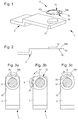
figures 1 et 2 représentent un schéma d'un premier mode de réalisation de l'ensemble de maintien selon l'invention; - Les
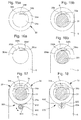
figures 3a à 3c représentent un schéma d'une première solution du premier mode de réalisation de l'ensemble de maintien selon l'invention; - Les
figures 4 et 5 représentent un schéma d'une seconde solution du premier mode de réalisation de l'ensemble de maintien selon l'invention; - La
figure 6 représente un schéma d'un second mode de réalisation de l'ensemble de maintien selon l'invention; - Les
figures 7a et 7b représentent un schéma d'une première solution du second mode de réalisation de l'ensemble de maintien selon l'invention; - Les
figures 8a à 8c représentent un schéma d'une seconde solution du second mode de réalisation de l'ensemble de maintien selon l'invention; - La
figure 9 représente un schéma d'une variante de la seconde solution du second mode de réalisation de l'ensemble de maintien selon l'invention; - Les
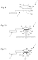
figures 10 et 11 représentent un schéma d'une première variante des premiers et seconds modes de réalisation de l'ensemble de maintien selon l'invention; - La
figure 12 représente un schéma d'une seconde variante des premiers et seconds modes de réalisation de l'ensemble de maintien selon l'invention; - La
figure 13 représente un schéma d'une alternative des premiers et seconds modes de réalisation de l'ensemble de maintien selon l'invention; - Les
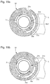
figures 14 ,17 et 18 représentent un schéma d'une troisième variante des modes de réalisation de l'ensemble de maintien selon l'invention; - Les
figures 15a, 15b, 16a et 16b ,19a et 19b représentent un schéma d'une autre variante des modes de réalisation de l'ensemble de maintien selon l'invention.
- The
Figures 1 and 2 represent a diagram of a first embodiment of the holding assembly according to the invention; - The
Figures 3a to 3c represent a diagram of a first solution of the first embodiment of the holding assembly according to the invention; - The
Figures 4 and 5 represent a diagram of a second solution of the first embodiment of the holding assembly according to the invention; - The
figure 6 represents a diagram of a second embodiment of the holding assembly according to the invention; - The
Figures 7a and 7b represent a diagram of a first solution of the second embodiment of the holding assembly according to the invention; - The
Figures 8a to 8c show a diagram of a second solution of the second embodiment of the holding assembly according to the invention; - The
figure 9 represents a diagram of a variant of the second solution of the second embodiment of the holding assembly according to the invention; - The
Figures 10 and 11 represent a diagram of a first variant of the first and second embodiments of the holding assembly according to the invention; - The
figure 12 represents a diagram of a second variant of the first and second embodiments of the holding assembly according to the invention; - The
figure 13 represents a diagram of an alternative of the first and second embodiments of the holding assembly according to the invention; - The
figures 14 ,17 and 18 represent a diagram of a third variant of the embodiments of the holding assembly according to the invention; - The
Figures 15a, 15b, 16a and 16b ,19a and 19b represent a diagram of another variant of the embodiments of the holding assembly according to the invention.
La présente invention procède de l'idée générale de fournir un ensemble de maintien ou d'appui d'un ressort spiral d'horlogerie permettant un montage/démontage du piton plus simple.The present invention proceeds from the general idea of providing a support or support assembly of a spiral clock spring for mounting / dismounting of the simplest piton.
Dans un premier mode de réalisation visible à la
Dans ce premier mode de réalisation visible aux
La première ouverture 34b est la partie la plus importante et est agencée pour coopérer avec le plot 31. On entend par là que le plot 31 s'insère dans la première ouverture 34a. La seconde ouverture 34b est utilisée pour le piton 9. En effet, le piton 9 s'insère dans la seconde ouverture 34b.The
Avantageusement selon l'invention, la forme du plot 31 et celle de la première ouverture 34a sont telles qu'elles permettent, lors de la rotation de la plaque de maintien par rapport audit plot, d'agir sur la poutre déformable 35. Cette déformation de ladite poutre permet de rétrécir la seconde ouverture 34b et donc de serrer le piton.Advantageously according to the invention, the shape of the
Dans une première solution visible aux
Cette zone distincte sera utilisée pour le serrage du piton 9. En effet, en faisant pivoter la plaque de maintien 32 par rapport au plot 31, la zone distincte du plot 31 va entrer en contact de la poutre déformable 35. Etant donné que la première ouverture 34a est circulaire, la zone distincte du plot 31 exerce une contrainte sur cette poutre déformable 35. Cette contrainte déforme ainsi la poutre 35 qui rétrécit la seconde ouverture 34b. Ce rétrécissement entraîne une contrainte exercée sur le piton 9 afin de le serrer.This distinct zone will be used for the clamping of the
Pour le montage, celui-ci se fait en montant la plaque 32 au niveau du coq 5 en insérant le plot 31 dans la première ouverture 34a de la plaque de maintien 32. La plaque de maintien 32 pourra être montée dans sa position angulaire définitive ou pas. Le plot 31 pourra être muni d'une rainure périphérique empêchant la plaque de maintien 32 de se désolidariser. Dans le cas où la plaque de maintien 32 est montée dans sa position angulaire définitive, la plaque de maintien 32 sera pivotée d'un certain angle dans le sens horaire ou antihoraire de sorte que la zone distincte ne soit plus en contact avec la poutre déformable 35. La contrainte appliquée par cette zone distincte est donc retirée et la seconde ouverture 34b reprend sa taille de repos comme visible à la
Le piton 9 est alors placé dans la seconde ouverture 34b puis la plaque de maintien 32 est mise en rotation par rapport au plot 31 pour rétrécir la seconde ouverture 34b et serrer le piton 9 sur la plaque de maintien 32 comme visible à la
Le plot 31 pourra être conçu comme étant une pièce circulaire munie d'une partie saillante ou d'une pièce de forme ovoïdale.The
Dans une seconde solution visible aux
Toutefois, le plot 31 est agencé de sorte que son axe principal s'étende parallèlement à l'axe longitudinal du coq (5) comme visible à la
Lors de la rotation de la plaque de maintien 32 pour effectuer le serrage du piton 9 inséré dans la seconde ouverture 34b, un des deux pôles c'est-à-dire une des deux zones les plus éloignées du centre du plot 31 entre en contact avec la poutre déformable 35. Cette poutre déformable 35 subit alors une contrainte de la part du plot 31 entraînant la déformation de ladite poutre 35. Cette déformation de ladite poutre 35 entraîne un rétrécissement de la seconde ouverture 34b et donc l'apparition d'une contrainte sur le piton 9 qui le serre comme visible à la
Dans un second mode de réalisation visible à la
La plaque de maintien 302 comprend en outre une poutre déformable 305 séparant l'orifice 304 en une première ouverture 304a et une seconde ouverture 304b. La première ouverture 304b est la partie la plus importante et est agencée pour coopérer avec le plot 301. On entend par là que le plot 301 s'insère dans la première ouverture 304a. La seconde ouverture 304b est utilisée pour le piton 9. En effet, le piton 9 s'insère dans la seconde ouverture 304b.The holding
Avantageusement selon l'invention, la forme du plot 302 et celle de la première ouverture 304a sont telles qu'elles permettent, lors de la rotation du plot 302 par rapport à la plaque de maintien, d'agir sur la poutre déformable 305. Cette déformation de ladite poutre permet de rétrécir la seconde ouverture 34b et donc de serrer le piton 9.Advantageously according to the invention, the shape of the
Dans une première solution visible aux
Cette zone distincte sera utilisée pour le serrage du piton 9. En effet, en faisant pivoter le plot 301 par rapport à la plaque de maintien 302, la zone distincte du plot 301 va entrer en contact de la poutre déformable 305. Etant donné que la première ouverture 304a est circulaire, la zone distincte du plot 301 exerce une contrainte sur cette poutre déformable 305. Cette contrainte déforme ainsi la poutre 305 qui rétrécit la seconde ouverture 304b. Ce rétrécissement entraine une contrainte exercée sur le piton 9 afin de le serrer.This distinct zone will be used for the clamping of the
Pour le montage, celui-ci se fait en montant le plot 301 au niveau du coq 5 en l'insérant dans la première ouverture 304a de la plaque de maintien 302. Le plot 301 pourra être monté dans sa position angulaire définitive ou pas. Dans le cas où le plot 301 est monté dans sa position angulaire définitive, le plot 301 sera pivoté d'un certain angle dans le sens horaire ou antihoraire de sorte que la zone distincte ne soit plus en contact avec la poutre déformable 305. La contrainte appliquée par cette zone distincte est donc retirée et la seconde ouverture 304b reprend sa taille de repos permettant le montage du piton 9.For mounting, it is done by mounting the
Le piton 9 est alors placé dans la seconde ouverture 304b puis le plot 301 est mis en rotation par rapport à la plaque de maintien 302 pour rétrécir la seconde ouverture 304b et serrer le piton 9 sur la plaque de maintien 302.The
Le plot 301 pourra être conçu comme étant une pièce circulaire muni d'une ouverture saillante ou d'une pièce de forme ovoïdale.The
Il est possible de régler la position angulaire du piton 9 en le faisant coulisser dans la seconde ouverture 304b.It is possible to adjust the angular position of the
Dans une seconde solution visible aux
Toutefois, la première ouverture 304a est agencée de sorte que sa longueur s'étende perpendiculairement à l'axe longitudinal du coq (5). Par conséquent, lors du montage de la plaque de maintien 302, le plot 301 est inséré dans la première ouverture. Le résultat est que l'axe longitudinal du plot 301 se trouve dans une position angulairement décalée par rapport à un alignement avec l'axe longitudinal du coq 5.However, the
Lors de la rotation du plot 301 pour effectuer le serrage du piton inséré dans la seconde ouverture, un des deux pôles c'est-à-dire une des deux zones les plus éloignées du centre du plot 301 entre en contact avec la poutre déformable 305. Cette poutre déformable 305 subit alors une contrainte de la part du plot 301 entrainant sa déformation. Cette déformation entraine un rétrécissement de la seconde ouverture 304b et donc l'apparition d'une contrainte sur le piton 9 afin de le serrer.During the rotation of the
Dans une variante visible à la
Pour le montage à rotation du plot 301 par rapport à la plaque de maintien 302 ou de la plaque de maintien 32 par rapport au plot 31, une interface male 700 et une interface femelle 702 sont agencées. L'interface male 700 et l'interface femelle 702 coopèrent ainsi ensemble de manière à permettre à la partie mobile d'être montée au coq 5 par un mouvement de rotation.For the rotational mounting of the
Selon une première alternative de réalisation, le montage à rotation est un montage à baïonnette. Dans le cas de la
L'interface male 700, située au niveau de la première ouverture 34a, consiste en au moins une partie saillante 701. Cette partie saillante 701 est située sur la tranche de la première ouverture 34a. Cette partie saillante 701 est agencée pour coopérer avec l'interface femelle 702 du plot.The
La plaque de maintien 32 est montée au niveau du plot 31 de sorte que les parties saillantes 701 de la plaque de maintien 32 puissent s'introduire dans le dégagement 702b dudit plot 31. Le plot peut alors être introduit dans la première ouverture. Lorsque le plot arrive en butée, les parties saillantes doivent se trouver en regard des gorges. Par conséquent, un mouvement de rotation est effectué pour introduire les parties saillantes dans lesdites gorges et fixer ledit plot au coq.The holding
Selon une seconde alternative, le montage à rotation est un montage par vissage. Pour cela, l'interface femelle et l'interface male consistent tous les deux en un pas de vis.According to a second alternative, the rotational mounting is a screw mounting. For this, the female interface and the male interface are both in a thread.
Dans une première variante des deux modes de réalisation visibles aux
Dans une seconde variante, visible à la
Dans une troisième variante des premier et second modes de réalisation, des moyens de réglage 800 sont prévus pour le réglage angulaire de la plaque de maintien pour modifier la position angulaire de ladite plaque de maintien par rapport au coq tout en conservant un bon serrage du piton.In a third variant of the first and second embodiments, adjustment means 800 are provided for the angular adjustment of the holding plate to modify the angular position of said holding plate relative to the cock while maintaining a good tightening of the peak .
Dans le cas du second mode de réalisation dans lequel le plot 301 est une pièce qui vient se rapportée sur la base et que la plaque de maintien 302 est fixée au coq 5,
les moyens de réglages 800 comprennent ainsi des moyens d'engagement 801 agencés sur la face de la plaque de maintien en regard du coq et une pluralité de réceptacles 802 agencés sur la face du coq en regard de la plaque de maintien comme visible à la
the adjustment means 800 thus comprise engagement means 801 arranged on the face of the holding plate facing the cock and a plurality of
Préférentiellement, la pluralité de tubes et la pluralité de trou sont disposées en cercle. Cet agencement a pour avantage de permettre de modifier angulairement la position de la plaque de maintien par rapport au coq et de verrouiller cette position angulaire. Une fois la position angulaire définie et verrouillée, les étapes de mise en place du piton et de serrage du piton à la plaque de maintien peuvent être opérées.Preferably, the plurality of tubes and the plurality of holes are arranged in a circle. This arrangement has the advantage of allowing angularly change the position of the holding plate relative to the cock and lock this angular position. Once the angular position defined and locked, the steps of setting the stud and clamping the stud to the holding plate can be operated.
Par conséquent, comme le plot est une pièce rapportée, il suffit simplement d'insérer ledit plot dans la première ouverture de la plaque de maintien et dans l'ouverture du coq et de le mettre en rotation pour venir agir sur la poutre déformable de la plaque de maintien pour serrer le piton.Therefore, as the stud is an insert, it suffices simply to insert said stud in the first opening of the holding plate and in the opening of the cock and to rotate it to act on the deformable beam of the holding plate to tighten the piton.
Dans le cas du premier mode de réalisation visible à la
Cette roue 810 comprend une fente 814 de sorte qu'un outil tel un tournevis à tète plate puis être utilisé pour agir sur la roue dentée 810.This
Ainsi, pour modifier la position angulaire du piton 9 , une personne engage la tête plate du tournevis dans la fente 814 de la roue dentée et met en rotation cette roue dentée 810. Cette roue dentée 810 engrène avec la denture 812 de la plaque de maintien entrainant la rotation de cette dernière.Thus, to change the angular position of the
Il peut être envisagé que les moyens de réglage 800 comprennent une seconde encoche 822 agencée sur la plaque de maintien et une première encoche 820 agencée au niveau du point de balancier 5 comme visible à la
Par ailleurs, dans une autre variante, on comprendra que le plot 31 et la plaque de maintien 32 ou la plaque de maintien 302 et le plot 301 soit agencés sur la face inférieure du coq 5 c'est-à-dire au niveau de la face se trouvant en regard du balancier spiral.Furthermore, in another variant, it will be understood that the
Dans une autre variante visible aux
A ce titre, il pourra être prévu une variante dans laquelle le bras déformable comprend une bosse ou saillie 35a' comme visible aux
Par ailleurs, il peut être prévu que le réglage angulaire de la plaque de maintien sur le coq se fasse en prévoyant deux trous oblongs au niveau de ladite plaque de maintien. Ces deux trous oblongs permettent la fixation de la plaque de maintien sur le coq tout en autorisant un degré de liberté dans la rotation. Préférentiellement, les trous oblongs seront réalisés de sorte que la plaque de maintien puisse se mettre en rotation autour du plot.Furthermore, it can be provided that the angular adjustment of the holding plate on the cock is done by providing two oblong holes at said holding plate. These two oblong holes allow the fixation of the support plate on the cock while allowing a degree of freedom in the rotation. Preferably, the oblong holes will be made so that the holding plate can rotate around the stud.
Il pourra être également prévu que la plaque de maintien 32 soit en outre munie d'au moins une encoche 32a au niveau de sa périphérie comme visible aux
De même, il pourra être prévu que le plot 301 servant d'amortisseur de chocs est utilisé comme butée en Z pour retenir le porte-piton lors des chocs.Similarly, it may be provided that the
Claims (18)
Priority Applications (1)
| Application Number | Priority Date | Filing Date | Title |
|---|---|---|---|
| EP15198646.0A EP3037896B1 (en) | 2014-12-22 | 2015-12-09 | Detachable stud support |
Applications Claiming Priority (2)
| Application Number | Priority Date | Filing Date | Title |
|---|---|---|---|
| EP14199751 | 2014-12-22 | ||
| EP15198646.0A EP3037896B1 (en) | 2014-12-22 | 2015-12-09 | Detachable stud support |
Publications (2)
| Publication Number | Publication Date |
|---|---|
| EP3037896A1 true EP3037896A1 (en) | 2016-06-29 |
| EP3037896B1 EP3037896B1 (en) | 2017-05-10 |
Family
ID=52134025
Family Applications (1)
| Application Number | Title | Priority Date | Filing Date |
|---|---|---|---|
| EP15198646.0A Active EP3037896B1 (en) | 2014-12-22 | 2015-12-09 | Detachable stud support |
Country Status (4)
| Country | Link |
|---|---|
| US (1) | US9785118B2 (en) |
| EP (1) | EP3037896B1 (en) |
| JP (1) | JP6147323B2 (en) |
| CN (2) | CN105717778B (en) |
Cited By (1)
| Publication number | Priority date | Publication date | Assignee | Title |
|---|---|---|---|---|
| CH714249A1 (en) * | 2017-10-16 | 2019-04-30 | Richemont Int Sa | Oscillator for watch movement. |
Families Citing this family (1)
| Publication number | Priority date | Publication date | Assignee | Title |
|---|---|---|---|---|
| EP3037896B1 (en) * | 2014-12-22 | 2017-05-10 | ETA SA Manufacture Horlogère Suisse | Detachable stud support |
Family Cites Families (10)
| Publication number | Priority date | Publication date | Assignee | Title |
|---|---|---|---|---|
| JPS4836706Y1 (en) * | 1969-09-27 | 1973-11-01 | ||
| JPS5223562U (en) * | 1975-08-07 | 1977-02-18 | ||
| CH609515GA3 (en) | 1976-09-14 | 1979-03-15 | Regulator work for timepiece with balance and hairspring | |
| EP2290477B1 (en) * | 2009-08-25 | 2014-06-11 | Glashütter Uhrenbetrieb GmbH | Assembly for fixing the peripheral end of the hairspring of a device with balance wheel-hairspring for a timepiece |
| EP2761380B1 (en) * | 2011-09-29 | 2023-05-31 | Rolex S.A. | Integral assembly of a hairspring and a collet |
| JP6118037B2 (en) * | 2012-05-08 | 2017-04-19 | セイコーインスツル株式会社 | Beardball, balance and watch |
| CH707815B1 (en) * | 2013-03-19 | 2017-05-31 | Nivarox Far Sa | Subassembly of a clockwork escapement mechanism comprising a spiral spring. |
| EP2876504B1 (en) * | 2013-11-20 | 2017-07-26 | ETA SA Manufacture Horlogère Suisse | Screwless clock stud holder |
| EP2887154B1 (en) * | 2013-12-20 | 2016-07-20 | Blancpain SA. | Mechanism for attaching a balance-spring stud to a balance bridge and regulating device with balance-hairspring including such a mechanism |
| EP3037896B1 (en) * | 2014-12-22 | 2017-05-10 | ETA SA Manufacture Horlogère Suisse | Detachable stud support |
-
2015
- 2015-12-09 EP EP15198646.0A patent/EP3037896B1/en active Active
- 2015-12-10 US US14/964,970 patent/US9785118B2/en active Active
- 2015-12-21 CN CN201510963875.6A patent/CN105717778B/en active Active
- 2015-12-21 JP JP2015248245A patent/JP6147323B2/en active Active
- 2015-12-21 CN CN201521070865.1U patent/CN205374996U/en not_active Withdrawn - After Issue
Cited By (1)
| Publication number | Priority date | Publication date | Assignee | Title |
|---|---|---|---|---|
| CH714249A1 (en) * | 2017-10-16 | 2019-04-30 | Richemont Int Sa | Oscillator for watch movement. |
Also Published As
| Publication number | Publication date |
|---|---|
| CN205374996U (en) | 2016-07-06 |
| EP3037896B1 (en) | 2017-05-10 |
| CN105717778B (en) | 2018-04-17 |
| US20160179059A1 (en) | 2016-06-23 |
| JP6147323B2 (en) | 2017-06-14 |
| CN105717778A (en) | 2016-06-29 |
| US9785118B2 (en) | 2017-10-10 |
| JP2016128806A (en) | 2016-07-14 |
Similar Documents
| Publication | Publication Date | Title |
|---|---|---|
| EP2672332B1 (en) | Improved rotating bezel system | |
| EP2876504B1 (en) | Screwless clock stud holder | |
| EP2859412B1 (en) | Rotating bezel system | |
| EP2437126B1 (en) | Balance wheel-hairspring regulator | |
| EP2887154B1 (en) | Mechanism for attaching a balance-spring stud to a balance bridge and regulating device with balance-hairspring including such a mechanism | |
| EP2799937B1 (en) | Shock-proof bearing for an horological balance | |
| EP3220211B1 (en) | Shock absorbing system with angular locking | |
| EP2804055A1 (en) | Regulator having a balance wheel, a spiral spring, a stud and a stud support and assembly consisting of a stud and a stud support | |
| EP3179315B1 (en) | Stud support with secure mounting | |
| EP3037896B1 (en) | Detachable stud support | |
| EP3179314B1 (en) | Stud support with simplified assembly | |
| EP3719583B1 (en) | Mechanical braking device for a clock mobile | |
| EP2864842A1 (en) | Shock-proof system with a simplified assembly for a timepiece | |
| EP3037895B1 (en) | Detachable stud support | |
| CH710571A2 (en) | Holding assembly or support of a timepiece balance spring with a peak and a carrier peak. | |
| EP3032353A1 (en) | Detachable stud support | |
| CH714000A1 (en) | Watchmaking assembly comprising a watch component fixed on an axis. | |
| EP3432082B1 (en) | Regulating mechanism | |
| CH711900A2 (en) | Piton mount with secure mounting. | |
| CH710550A2 (en) | removable stud support. | |
| CH710491A2 (en) | Holding assembly or support of a timepiece balance spring. | |
| CH706640B1 (en) | Shockproof bearing for timepiece. | |
| CH711899A2 (en) | Holder or support assembly of a spiral clockwork spring comprising a stud and a stud holder. | |
| EP3428738A1 (en) | Drive and positioning system and jumper for implementing said system | |
| CH714249B1 (en) | Oscillator for watch movement. |
Legal Events
| Date | Code | Title | Description |
|---|---|---|---|
| PUAI | Public reference made under article 153(3) epc to a published international application that has entered the european phase |
Free format text: ORIGINAL CODE: 0009012 |
|
| AK | Designated contracting states |
Kind code of ref document: A1 Designated state(s): AL AT BE BG CH CY CZ DE DK EE ES FI FR GB GR HR HU IE IS IT LI LT LU LV MC MK MT NL NO PL PT RO RS SE SI SK SM TR |
|
| AX | Request for extension of the european patent |
Extension state: BA ME |
|
| 17P | Request for examination filed |
Effective date: 20170102 |
|
| RBV | Designated contracting states (corrected) |
Designated state(s): AL AT BE BG CH CY CZ DE DK EE ES FI FR GB GR HR HU IE IS IT LI LT LU LV MC MK MT NL NO PL PT RO RS SE SI SK SM TR |
|
| GRAP | Despatch of communication of intention to grant a patent |
Free format text: ORIGINAL CODE: EPIDOSNIGR1 |
|
| RIC1 | Information provided on ipc code assigned before grant |
Ipc: G04D 1/06 20060101ALI20170215BHEP Ipc: G04D 1/04 20060101ALI20170215BHEP Ipc: G04B 17/32 20060101AFI20170215BHEP |
|
| INTG | Intention to grant announced |
Effective date: 20170303 |
|
| GRAS | Grant fee paid |
Free format text: ORIGINAL CODE: EPIDOSNIGR3 |
|
| GRAA | (expected) grant |
Free format text: ORIGINAL CODE: 0009210 |
|
| AK | Designated contracting states |
Kind code of ref document: B1 Designated state(s): AL AT BE BG CH CY CZ DE DK EE ES FI FR GB GR HR HU IE IS IT LI LT LU LV MC MK MT NL NO PL PT RO RS SE SI SK SM TR |
|
| REG | Reference to a national code |
Ref country code: GB Ref legal event code: FG4D Free format text: NOT ENGLISH |
|
| REG | Reference to a national code |
Ref country code: AT Ref legal event code: REF Ref document number: 892963 Country of ref document: AT Kind code of ref document: T Effective date: 20170515 Ref country code: CH Ref legal event code: EP Ref country code: CH Ref legal event code: NV Representative=s name: ICB INGENIEURS CONSEILS EN BREVETS SA, CH |
|
| REG | Reference to a national code |
Ref country code: IE Ref legal event code: FG4D Free format text: LANGUAGE OF EP DOCUMENT: FRENCH |
|
| REG | Reference to a national code |
Ref country code: DE Ref legal event code: R096 Ref document number: 602015002654 Country of ref document: DE |
|
| REG | Reference to a national code |
Ref country code: NL Ref legal event code: MP Effective date: 20170510 |
|
| REG | Reference to a national code |
Ref country code: LT Ref legal event code: MG4D |
|
| REG | Reference to a national code |
Ref country code: AT Ref legal event code: MK05 Ref document number: 892963 Country of ref document: AT Kind code of ref document: T Effective date: 20170510 |
|
| PG25 | Lapsed in a contracting state [announced via postgrant information from national office to epo] |
Ref country code: ES Free format text: LAPSE BECAUSE OF FAILURE TO SUBMIT A TRANSLATION OF THE DESCRIPTION OR TO PAY THE FEE WITHIN THE PRESCRIBED TIME-LIMIT Effective date: 20170510 Ref country code: GR Free format text: LAPSE BECAUSE OF FAILURE TO SUBMIT A TRANSLATION OF THE DESCRIPTION OR TO PAY THE FEE WITHIN THE PRESCRIBED TIME-LIMIT Effective date: 20170811 Ref country code: AT Free format text: LAPSE BECAUSE OF FAILURE TO SUBMIT A TRANSLATION OF THE DESCRIPTION OR TO PAY THE FEE WITHIN THE PRESCRIBED TIME-LIMIT Effective date: 20170510 Ref country code: HR Free format text: LAPSE BECAUSE OF FAILURE TO SUBMIT A TRANSLATION OF THE DESCRIPTION OR TO PAY THE FEE WITHIN THE PRESCRIBED TIME-LIMIT Effective date: 20170510 Ref country code: FI Free format text: LAPSE BECAUSE OF FAILURE TO SUBMIT A TRANSLATION OF THE DESCRIPTION OR TO PAY THE FEE WITHIN THE PRESCRIBED TIME-LIMIT Effective date: 20170510 Ref country code: LT Free format text: LAPSE BECAUSE OF FAILURE TO SUBMIT A TRANSLATION OF THE DESCRIPTION OR TO PAY THE FEE WITHIN THE PRESCRIBED TIME-LIMIT Effective date: 20170510 Ref country code: NO Free format text: LAPSE BECAUSE OF FAILURE TO SUBMIT A TRANSLATION OF THE DESCRIPTION OR TO PAY THE FEE WITHIN THE PRESCRIBED TIME-LIMIT Effective date: 20170810 |
|
| REG | Reference to a national code |
Ref country code: FR Ref legal event code: PLFP Year of fee payment: 3 |
|
| PG25 | Lapsed in a contracting state [announced via postgrant information from national office to epo] |
Ref country code: IS Free format text: LAPSE BECAUSE OF FAILURE TO SUBMIT A TRANSLATION OF THE DESCRIPTION OR TO PAY THE FEE WITHIN THE PRESCRIBED TIME-LIMIT Effective date: 20170910 Ref country code: SE Free format text: LAPSE BECAUSE OF FAILURE TO SUBMIT A TRANSLATION OF THE DESCRIPTION OR TO PAY THE FEE WITHIN THE PRESCRIBED TIME-LIMIT Effective date: 20170510 Ref country code: NL Free format text: LAPSE BECAUSE OF FAILURE TO SUBMIT A TRANSLATION OF THE DESCRIPTION OR TO PAY THE FEE WITHIN THE PRESCRIBED TIME-LIMIT Effective date: 20170510 Ref country code: PL Free format text: LAPSE BECAUSE OF FAILURE TO SUBMIT A TRANSLATION OF THE DESCRIPTION OR TO PAY THE FEE WITHIN THE PRESCRIBED TIME-LIMIT Effective date: 20170510 Ref country code: BG Free format text: LAPSE BECAUSE OF FAILURE TO SUBMIT A TRANSLATION OF THE DESCRIPTION OR TO PAY THE FEE WITHIN THE PRESCRIBED TIME-LIMIT Effective date: 20170810 Ref country code: LV Free format text: LAPSE BECAUSE OF FAILURE TO SUBMIT A TRANSLATION OF THE DESCRIPTION OR TO PAY THE FEE WITHIN THE PRESCRIBED TIME-LIMIT Effective date: 20170510 Ref country code: RS Free format text: LAPSE BECAUSE OF FAILURE TO SUBMIT A TRANSLATION OF THE DESCRIPTION OR TO PAY THE FEE WITHIN THE PRESCRIBED TIME-LIMIT Effective date: 20170510 |
|
| PG25 | Lapsed in a contracting state [announced via postgrant information from national office to epo] |
Ref country code: CZ Free format text: LAPSE BECAUSE OF FAILURE TO SUBMIT A TRANSLATION OF THE DESCRIPTION OR TO PAY THE FEE WITHIN THE PRESCRIBED TIME-LIMIT Effective date: 20170510 Ref country code: EE Free format text: LAPSE BECAUSE OF FAILURE TO SUBMIT A TRANSLATION OF THE DESCRIPTION OR TO PAY THE FEE WITHIN THE PRESCRIBED TIME-LIMIT Effective date: 20170510 Ref country code: DK Free format text: LAPSE BECAUSE OF FAILURE TO SUBMIT A TRANSLATION OF THE DESCRIPTION OR TO PAY THE FEE WITHIN THE PRESCRIBED TIME-LIMIT Effective date: 20170510 Ref country code: SK Free format text: LAPSE BECAUSE OF FAILURE TO SUBMIT A TRANSLATION OF THE DESCRIPTION OR TO PAY THE FEE WITHIN THE PRESCRIBED TIME-LIMIT Effective date: 20170510 Ref country code: RO Free format text: LAPSE BECAUSE OF FAILURE TO SUBMIT A TRANSLATION OF THE DESCRIPTION OR TO PAY THE FEE WITHIN THE PRESCRIBED TIME-LIMIT Effective date: 20170510 |
|
| REG | Reference to a national code |
Ref country code: DE Ref legal event code: R097 Ref document number: 602015002654 Country of ref document: DE |
|
| PG25 | Lapsed in a contracting state [announced via postgrant information from national office to epo] |
Ref country code: IT Free format text: LAPSE BECAUSE OF FAILURE TO SUBMIT A TRANSLATION OF THE DESCRIPTION OR TO PAY THE FEE WITHIN THE PRESCRIBED TIME-LIMIT Effective date: 20170510 Ref country code: SM Free format text: LAPSE BECAUSE OF FAILURE TO SUBMIT A TRANSLATION OF THE DESCRIPTION OR TO PAY THE FEE WITHIN THE PRESCRIBED TIME-LIMIT Effective date: 20170510 |
|
| PLBE | No opposition filed within time limit |
Free format text: ORIGINAL CODE: 0009261 |
|
| STAA | Information on the status of an ep patent application or granted ep patent |
Free format text: STATUS: NO OPPOSITION FILED WITHIN TIME LIMIT |
|
| 26N | No opposition filed |
Effective date: 20180213 |
|
| REG | Reference to a national code |
Ref country code: IE Ref legal event code: MM4A |
|
| PG25 | Lapsed in a contracting state [announced via postgrant information from national office to epo] |
Ref country code: MT Free format text: LAPSE BECAUSE OF FAILURE TO SUBMIT A TRANSLATION OF THE DESCRIPTION OR TO PAY THE FEE WITHIN THE PRESCRIBED TIME-LIMIT Effective date: 20170510 Ref country code: LU Free format text: LAPSE BECAUSE OF NON-PAYMENT OF DUE FEES Effective date: 20171209 |
|
| REG | Reference to a national code |
Ref country code: BE Ref legal event code: MM Effective date: 20171231 |
|
| PG25 | Lapsed in a contracting state [announced via postgrant information from national office to epo] |
Ref country code: IE Free format text: LAPSE BECAUSE OF NON-PAYMENT OF DUE FEES Effective date: 20171209 |
|
| PG25 | Lapsed in a contracting state [announced via postgrant information from national office to epo] |
Ref country code: BE Free format text: LAPSE BECAUSE OF NON-PAYMENT OF DUE FEES Effective date: 20171231 |
|
| PG25 | Lapsed in a contracting state [announced via postgrant information from national office to epo] |
Ref country code: MC Free format text: LAPSE BECAUSE OF FAILURE TO SUBMIT A TRANSLATION OF THE DESCRIPTION OR TO PAY THE FEE WITHIN THE PRESCRIBED TIME-LIMIT Effective date: 20170510 Ref country code: HU Free format text: LAPSE BECAUSE OF FAILURE TO SUBMIT A TRANSLATION OF THE DESCRIPTION OR TO PAY THE FEE WITHIN THE PRESCRIBED TIME-LIMIT; INVALID AB INITIO Effective date: 20151209 |
|
| PG25 | Lapsed in a contracting state [announced via postgrant information from national office to epo] |
Ref country code: SI Free format text: LAPSE BECAUSE OF FAILURE TO SUBMIT A TRANSLATION OF THE DESCRIPTION OR TO PAY THE FEE WITHIN THE PRESCRIBED TIME-LIMIT Effective date: 20170510 |
|
| PG25 | Lapsed in a contracting state [announced via postgrant information from national office to epo] |
Ref country code: CY Free format text: LAPSE BECAUSE OF FAILURE TO SUBMIT A TRANSLATION OF THE DESCRIPTION OR TO PAY THE FEE WITHIN THE PRESCRIBED TIME-LIMIT Effective date: 20170510 |
|
| PG25 | Lapsed in a contracting state [announced via postgrant information from national office to epo] |
Ref country code: MK Free format text: LAPSE BECAUSE OF FAILURE TO SUBMIT A TRANSLATION OF THE DESCRIPTION OR TO PAY THE FEE WITHIN THE PRESCRIBED TIME-LIMIT Effective date: 20170510 |
|
| PG25 | Lapsed in a contracting state [announced via postgrant information from national office to epo] |
Ref country code: TR Free format text: LAPSE BECAUSE OF FAILURE TO SUBMIT A TRANSLATION OF THE DESCRIPTION OR TO PAY THE FEE WITHIN THE PRESCRIBED TIME-LIMIT Effective date: 20170510 |
|
| PG25 | Lapsed in a contracting state [announced via postgrant information from national office to epo] |
Ref country code: PT Free format text: LAPSE BECAUSE OF FAILURE TO SUBMIT A TRANSLATION OF THE DESCRIPTION OR TO PAY THE FEE WITHIN THE PRESCRIBED TIME-LIMIT Effective date: 20170510 |
|
| PG25 | Lapsed in a contracting state [announced via postgrant information from national office to epo] |
Ref country code: AL Free format text: LAPSE BECAUSE OF FAILURE TO SUBMIT A TRANSLATION OF THE DESCRIPTION OR TO PAY THE FEE WITHIN THE PRESCRIBED TIME-LIMIT Effective date: 20170510 |
|
| GBPC | Gb: european patent ceased through non-payment of renewal fee |
Effective date: 20191209 |
|
| PG25 | Lapsed in a contracting state [announced via postgrant information from national office to epo] |
Ref country code: GB Free format text: LAPSE BECAUSE OF NON-PAYMENT OF DUE FEES Effective date: 20191209 |
|
| PGFP | Annual fee paid to national office [announced via postgrant information from national office to epo] |
Ref country code: CH Payment date: 20230101 Year of fee payment: 8 |
|
| P01 | Opt-out of the competence of the unified patent court (upc) registered |
Effective date: 20230701 |
|
| PGFP | Annual fee paid to national office [announced via postgrant information from national office to epo] |
Ref country code: FR Payment date: 20231122 Year of fee payment: 9 Ref country code: DE Payment date: 20231121 Year of fee payment: 9 |
|
| PGFP | Annual fee paid to national office [announced via postgrant information from national office to epo] |
Ref country code: CH Payment date: 20240101 Year of fee payment: 9 |