EP2672332B1 - Improved rotating bezel system - Google Patents
Improved rotating bezel system Download PDFInfo
- Publication number
- EP2672332B1 EP2672332B1 EP12171071.9A EP12171071A EP2672332B1 EP 2672332 B1 EP2672332 B1 EP 2672332B1 EP 12171071 A EP12171071 A EP 12171071A EP 2672332 B1 EP2672332 B1 EP 2672332B1
- Authority
- EP
- European Patent Office
- Prior art keywords
- ring
- bezel
- spring
- recess
- toothing
- Prior art date
- Legal status (The legal status is an assumption and is not a legal conclusion. Google has not performed a legal analysis and makes no representation as to the accuracy of the status listed.)
- Active
Links
Images


Classifications
-
- G—PHYSICS
- G04—HOROLOGY
- G04B—MECHANICALLY-DRIVEN CLOCKS OR WATCHES; MECHANICAL PARTS OF CLOCKS OR WATCHES IN GENERAL; TIME PIECES USING THE POSITION OF THE SUN, MOON OR STARS
- G04B19/00—Indicating the time by visual means
- G04B19/28—Adjustable guide marks or pointers for indicating determined points of time
- G04B19/283—Adjustable guide marks or pointers for indicating determined points of time on rotatable rings, i.e. bezel
- G04B19/286—Adjustable guide marks or pointers for indicating determined points of time on rotatable rings, i.e. bezel with locking means to prevent undesired rotations in both directions
-
- G—PHYSICS
- G01—MEASURING; TESTING
- G01C—MEASURING DISTANCES, LEVELS OR BEARINGS; SURVEYING; NAVIGATION; GYROSCOPIC INSTRUMENTS; PHOTOGRAMMETRY OR VIDEOGRAMMETRY
- G01C23/00—Combined instruments indicating more than one navigational value, e.g. for aircraft; Combined measuring devices for measuring two or more variables of movement, e.g. distance, speed or acceleration
Definitions
- the present invention relates to a timepiece comprising a middle part closed by a bottom and an ice, said timepiece further comprising a rotating bezel system attached to said middle part.
- the technical field of the invention is the technical field of fine mechanics.
- the present invention relates to a rotating bezel for a timepiece.
- Rotating eyewear systems 2 known, visible to the figure 1 , comprise a rotating bezel 4 in the form of an annular piece having an upper face and a lower face, the upper face being the face visible by the user.
- This bezel comprises, on its lower surface, a notch 6.
- the rotating bezel system further comprises a spring means 8.
- This spring means 8 is inserted between the rotating bezel and the middle part 3 of the timepiece 1 when the bezel 4 is mounted to force on the middle part of the timepiece.
- This spring means 8 is in the form of a flat ring comprising, on its face facing the notch of the bezel, lamellae. These slats are arranged to have an inclination relative to the plane of the flat ring. These slats have a certain elasticity so that the spring means act on the rotating bezel to exert a vertical force. This vertical force tends to push the bezel out of the middle of the timepiece.
- these strips serve to cooperate with the notching of the underside of the bezel.
- the slats and notching are then configured so that the bezel can rotate in one direction.
- the slats oppose the rotation of the telescope if the user tries to rotate the telescope in the wrong direction.
- the bezel and the spring means are made of steel which has the advantage of having a good life and being inexpensive.
- This bezel is attached to the middle of the watch case by hunting.
- the middle part having a peripheral shoulder in which said rotating bezel system is placed, the vertical wall of said shoulder having a peripheral groove 10.
- the bezel is an annular piece having, on its underside, a peripheral rim.
- This flange is provided with a continuous projection 12 extending along said flange towards the axial center of the telescope.
- a disadvantage of this system is that it requires a large force to mount said rotating bezel system. Indeed, when the bezel is force-fitted on said middle so that the continuous projection fits into the peripheral groove, significant stresses are applied to the bezel. These constraints can, if they are poorly applied, lead to deformations of the telescope and therefore a malfunction of the rotating bezel system.
- the object of the invention is to overcome the drawbacks of the prior art by proposing to provide a timepiece rotating bezel system whose assembly on the watch case is simpler, while imposing less stress on said system and which makes it easier to disassemble.
- the invention relates to a timepiece comprising, inter alia, a middle closed by a bottom and an ice, said case having a peripheral shoulder in which is arranged a groove, said groove being disposed on a face of the shoulder parallel to the central axis of the middle part, said timepiece comprising a rotating bezel system rotatably mounted on said peripheral shoulder, characterized in that said rotating bezel system comprises a bezel ring provided with at least a first recess disposed on a face of the telescope intended to come opposite said groove when said rotating bezel system is mounted on the middle part, said rotating bezel system further comprising spring means extending both in said at less a first recess of the bezel and both in the groove of the middle to maintain the rotating bezel system to the ca rrure of the timepiece.
- a first advantage of the present invention is to allow the rotating bezel system according to the invention to be easier to assemble.
- the system according to the present invention is in the form of a pre-assembled system. It is then understood that the various elements constituting the rotating bezel system are assembled together and that it suffices, after that, to fix said system to the middle part of the watch case. Thus, the storage and transport of the rotating bezel systems are simpler because they are already mounted
- a second advantage is that the present invention allows a mounting requiring fewer constraints. Indeed, as the means are the means to retain the system of rotating bezel at the middle of the watch case, the stress exerted during the assembly is partly absorbed. This stress is absorbed by the spring which will deform and facilitate assembly.
- the spring means comprise a spring ring in the form of an open ring having at least one zone having a minimum radius and an area having a maximum radius so that the zone having a maximum radius cooperates with said at least one first recess and that the zone having a minimum radius cooperates with the groove of the peripheral shoulder.
- the rotating bezel system further comprises a toothed element having a toothing arranged to cooperate with a corresponding toothing arranged on the spring means for indexing at the angular position of the bezel.
- the bezel comprises a second recess in which the toothed element is arranged.
- said spring ring is a flat ring whose teeth are arranged on the outer wall of said at least one zone having a minimum radius, the first and second recesses then being merged.
- said spring ring comprises two ends, one of which has a raised portion, said raised portion comprising a vertically oriented curved portion and a flat portion parallel to said spring ring, said flat portion comprising, on its outer wall. , the toothing cooperating with the toothed element.
- the bezel is made in at least two parts and comprises a bezel ring and a support ring both having a complementary profile so that the assembly of the bezel ring to the ring of support makes it possible to form the first and second recesses combined.
- the bezel is made in at least two parts and comprises a bezel ring and a support ring both having a complementary profile so that the assembly of the bezel ring to the ring of support makes it possible to form the second recess, said support ring comprising the first recess.
- said spring ring comprises three zones having a minimum radius angularly distributed.
- the zones having a minimum radius of said spring ring are angularly distributed.
- said toothing is arranged on each zone having a maximum radius.
- the present invention proceeds from the general inventive idea of providing a rotating bezel system which is easier to assemble.
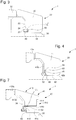
- a timepiece 1 visible at the figure 2 comprises a middle 30 closed by a bottom 31 and a mirror 32.
- This middle part 30 comprises a peripheral shoulder 34 defined by a side wall 36 and a base 38.
- This shoulder 34 defines a location in which the rotating bezel system 20 is placed.
- the rotating bezel system 20, visible at the figure 3 includes a telescope 40 which is the visible part and manipulated by the user.
- the rotating bezel system 20 also comprises a toothed element 60 arranged at the bezel 40 and spring means 80 cooperating with the toothed element 60 to allow rotation of the rotating bezel system 20 relative to the middle part 30 of the part watchmaking 1.
- the spring means 80 are also used to maintain the rotating bezel system 20 at the middle 30 of the watch case 1.
- the spring means 80 are in the form of a multi-level spring, in three dimensions.
- the rotating bezel system 20 of this embodiment comprises a telescope 41.
- This telescope 41 is for example in the form of a ring comprising an upper face 41a and a lower face 41b. From this lower face 41b, a peripheral rim 42 extends perpendicular to the plane of the telescope 41.
- This rim device 42 includes an inner side wall 42a and an outer side wall 42b.
- the inner side wall 42a includes a second recess 44 having a parallelepipedal profile such as a square or rectangular profile. This second recess 44 traverses the entire length of said rim 42 so as to be circular. In this second recess 44 is arranged the toothed element 60.
- This toothed element 60 may be in the form of a toothing 61 made directly in said first recess of the rim or, as in the example shown, in the form of a toothed ring 62 carrying, on its inner face, a toothing 63.
- This toothed ring 62 is placed in said second recess 44.
- Means for angularly securing said toothed ring 62 to the bezel 41 are provided, such as for example solder or glue. Nevertheless, it can be provided that the toothing 63 forming the toothed element 60 can be made directly on the inner side wall 42a of the peripheral flange 42, the latter not including a second recess 44.
- the spring means 80 visible to figures 5 and 6 are in the form of a spring ring 82.
- This spring ring has an upper face and a lower face, said upper face being the visible face from a top view when said spring ring is placed on any plane.
- the latter comprises an open ring 800 comprising at least one zone having a radius of curvature smaller than the radius of curvature of said non-closed ring. It is then understood that said spring ring comprises at least one zone 802 having a maximum radius and at least one zone 804 having a minimum radius. In the case shown in figure 5 , the spring ring comprises three zones 802 having a maximum radius spaced angularly regularly.
- Said open ring 800 also has, at one of its ends 806, an elevation 808.
- said end has an axial or vertical curvature so that this end is raised and parallel to the plane of the spring ring 800.
- raised portion then comprises a curved portion 808a oriented axially and a flat portion 808b parallel to said spring ring 82.
- this curvature extends from the upper face of the spring ring 82.
- This raised portion 808 comprises, on its outer face, a toothing 810.
- This toothing 810 is complementary to the toothing of the toothed element 60 that is to say the toothing 63 of the toothed ring 62 or the toothing 61. Indeed, when the spring ring 82 is mounted in the rotating bezel system 20, the elevation of the ring spring 82 is calculated such that the latter is opposite the toothed ring 62.
- the latter comprises a spring recess 46 having a square or rectangular profile also traversing the entire length of said flange 42.
- This first recess 46 is located below the second recess 44 so that a separating wall 48 separates the second recess 44 from the first recess 46.
- the separating wall 48 is preferably shortened so that the second recess 44 and the first recess 46 communicate with each other so that to form a housing 45 for the spring ring 82. Therefore, when mounting the spring ring 82, the toothing 810 of the outer face of the raised portion 808 comes into contact with the toothing of the inner face of the toothed ring 62, the spring ring 82 is embedded in said bezel 41.
- the at least one zone 804 having a minimum radius are inserted into the first recess 46. Accordingly, when the toothed ring 62 and the year the spring 82 are mounted in the bezel 41, only the at least one area 802 having a maximum radius protrude.
- each tooth comprises an inclined face and a right face or coincides with the radius of the toothed ring 62 or the spring ring 82.
- the inclined face of each tooth of the toothing 810 of the spring ring 82 is in contact with the inclined face of each tooth of the toothing 63 of the toothed ring 62.
- the rotation of the system is unidirectional, that is to say that the rotation can be done clockwise or counterclockwise but it is possible that the rotation is bidirectional. Indeed, if the rotating bezel system 20 is rotated in the right direction, the inclined faces of the toothing of the spring ring 82 and the toothing of the toothed ring 62 slide over each other to engage. By cons, if the rotating bezel system 20 is rotated in the wrong direction, the straight faces of the toothed ring 62 bear on the straight faces of the spring ring 82 operating a blocking.
- the side wall 36 of the shoulder 34 of the middle part 30 comprises a groove 37 extending along the side wall 36 so as to go around the shoulder 34.
- This groove 37 is used to fix said telescope system 20.
- the driving of said rotating bezel system 20 causes the application of a tension stress on the spring ring 82.
- This constraint As a result, the spring ring 82 is stretched and sees its diameter increase, the latter having a tendency to enter entirely into the first recess 46 thus facilitating the driving.
- the spring ring 82 has on its inner face 803, at least one projection 812.
- This projection 812 is made to cooperate with a hole 39 located on the middle part 30 as visible in FIG. figure 5 .
- This hole 39 is placed so that the projection 812 fits into it when the rotating bezel system 20 is mounted on the middle part 30. This cooperation induces an angular locking of the spring ring 82 relative to the middle part 30 .
- An advantage of the rotating bezel system 20 according to the invention is that its mounting on the middle part 30 is facilitated because the stress to be exerted is lower. Indeed, in known systems, the vertical holding is achieved by driving a rigid element which requires to exert a large force to drive the rotating bezel system 20. This also causes the operation of separating the system rotating bezel 20 of the middle part 30 is very complicated because the risk of breaking said system is important. With the rotating bezel system 20 according to the invention using an elastic element to ensure vertical retention, it is the spring ring 82 which is used for the vertical holding and which is deformed during the driving operation. The constraint to be applied to assemble the rotating bezel system 20 according to the invention to the middle part 30 is therefore less important. The consequence is that the detaching operation of the rotating bezel system 20 of the middle part 30 is less complicated. Another consequence is a decrease in the risk of breaking said rotating bezel system 20.
- the bezel 41 is composed of several parts.
- This bezel 41 comprises a bezel ring 410 and a support member 412 assembling together.
- the bezel ring 410 consists of a ring comprising an upper face 410a and a lower face 410b.
- the support member 412 is in the form of a support ring 413 having an upper face and a lower face.
- the upper face comprises a peripheral upper rim 414 having a stair profile. It is thus understood that said flange has several levels or bearing surface.
- the peripheral upper flange 414 will comprise at least one intermediate level, the support member 412 thus comprises three bearing surfaces at three different heights.
- the lower face comprises a peripheral lower flange 416 extending perpendicularly to the plane of the support member 412.
- the latter comprises a first recess 418 traversing the inner surface of the second flange 416 so as to form a circular recess.
- the bezel ring 410 also has a profile in the form of a staircase but complementary. This profile in the form of a complementary staircase is made to cooperate with the staircase profile of the support element 412.
- the toothed ring 62 is placed on one of the bearing surfaces of the support ring 412, preferably the lower surface.
- the bezel ring 410 is assembled to the support ring 413 by driving or screwing or other means of attachment.
- the staircase profiles of the bezel ring 410 and the support ring 413 cooperate together.
- the stepped profiles are arranged to form the second recess 44 in which the toothed ring 62 is placed.
- the toothed ring 62 is caught between the bezel ring 410 and the support ring 413.
- the spring ring 82 is fixed to the bezel 41 so that the areas having a maximum radius 802 fit into the first recess 418 of the lower flange 416.
- the raised portion 808 of the spring ring 82, and more particularly the toothing 810 of this raised portion cooperates with the toothing of the toothed ring 62.
- the spring ring 82 does not include elevation.
- Said spring ring 82 is an open or non-closed ring 820 comprising at least one zone having a maximum radius 822 and at least one zone having a minimum radius 821.
- the spring ring comprises three zones having a maximum radius 822, angularly spaced regularly.
- This second embodiment is distinguished in that the toothing 823 cooperating with the toothing of the toothed element 62 is placed on the said at least one zone having a maximum radius 822. This arrangement makes it possible to simplify the bezel since only one recess must be provided. arranged on the inner wall of the telescope or support element as visible in figure 3 .
Description
La présente invention concerne une pièce d'horlogerie comprenant une carrure fermée par un fond et une glace, ladite pièce d'horlogerie comprenant en outre un système de lunette tournante fixé à ladite carrure.The present invention relates to a timepiece comprising a middle part closed by a bottom and an ice, said timepiece further comprising a rotating bezel system attached to said middle part.
Le domaine technique de l'invention est le domaine technique de la mécanique fine.The technical field of the invention is the technical field of fine mechanics.
La présente invention concerne une lunette tournante pour pièce d'horlogerie.The present invention relates to a rotating bezel for a timepiece.
Des systèmes de lunettes tournantes 2 connues, visibles à la
De plus, ces lamelles servent à coopérer avec le crantage de la face inférieure de la lunette. Les lamelles et le crantage sont alors configurés de sorte que la lunette ne puisse tourner que dans un seul sens. Les lamelles s'opposent à la rotation de la lunette si l'utilisateur tente de faire tourner ladite lunette dans le mauvais sens. En général, la lunette et les moyens ressorts sont réalisés en acier qui a l'avantage d'avoir une bonne durée de vie et d'être peu coûteux.In addition, these strips serve to cooperate with the notching of the underside of the bezel. The slats and notching are then configured so that the bezel can rotate in one direction. The slats oppose the rotation of the telescope if the user tries to rotate the telescope in the wrong direction. In general, the bezel and the spring means are made of steel which has the advantage of having a good life and being inexpensive.
Cette lunette est fixée à la carrure de la boîte de montre par chassage. Pour cela, la carrure présentant un épaulement périphérique dans lequel ledit système de lunette tournante est placé, la paroi verticale dudit épaulement présentant une gorge périphérique 10. La lunette est une pièce annulaire présentant, sur sa face inférieure, un rebord périphérique. Ce rebord est muni d'une saillie 12 continue s'étendant le long dudit rebord vers le centre axial de la lunette. Lorsque ledit système de lunette tournante est monté sur la carrure de la boîte de montre par chassage, la saillie continue s'insère dans la gorge périphérique de l'épaulement assurant un maintien vertical de la lunette sur la carrure.This bezel is attached to the middle of the watch case by hunting. For this, the middle part having a peripheral shoulder in which said rotating bezel system is placed, the vertical wall of said shoulder having a
Un inconvénient de ce système est qu'il nécessite une force importante pour monter ledit système de lunette tournante. En effet, lorsque la lunette est montée à force sur ladite carrure pour que la saillie continue s'insère dans la gorge périphérique, des contraintes importantes sont appliquées sur la lunette. Ces contraintes peuvent, si elles sont mal appliquées, entraîner des déformations de la lunette et donc un mauvais fonctionnement du système de lunette tournante.A disadvantage of this system is that it requires a large force to mount said rotating bezel system. Indeed, when the bezel is force-fitted on said middle so that the continuous projection fits into the peripheral groove, significant stresses are applied to the bezel. These constraints can, if they are poorly applied, lead to deformations of the telescope and therefore a malfunction of the rotating bezel system.
Par ailleurs, cette opération de montage de la lunette par enfoncement à force est définitive. Effectivement, il est impossible par la suite de retirer le système de lunette tournante de la carrure. Les tentatives pour retirer ledit système de lunette tournante ont pour conséquence une destruction dudit système.Moreover, this mounting operation of the bezel by pressing force is final. Indeed, it is impossible subsequently to remove the rotating bezel system from the caseband. Attempts to remove said rotating bezel system result in destruction of said system.
La présente invention est définie par les revendications annexées.The present invention is defined by the appended claims.
L'invention a pour but de pallier les inconvénients de l'art antérieur en proposant de fournir un système de lunette tournante de pièce d'horlogerie dont le montage sur la boîte de montre est plus simple, tout en imposant moins de contrainte audit système et qui permet d'être démonter plus facilement.The object of the invention is to overcome the drawbacks of the prior art by proposing to provide a timepiece rotating bezel system whose assembly on the watch case is simpler, while imposing less stress on said system and which makes it easier to disassemble.
A cet effet, l'invention concerne une pièce d'horlogerie comprenant, inter alia, une carrure fermée par un fond et une glace, ladite carrure comportant un épaulement périphérique dans lequel est agencée une gorge, ladite gorge étant disposée sur une face de l'épaulement parallèle à l'axe central de la carrure, ladite pièce d'horlogerie comprenant un système de lunette tournante monté à rotation sur ledit épaulement périphérique, caractérisée en ce que ledit système de lunette tournante comprend un anneau formant lunette muni d'au moins un premier évidement disposé sur une face de la lunette destinée à venir en regard de ladite gorge lorsque ledit système de lunette tournante est monté sur la carrure, ledit système de lunette tournante comprenant en outre des moyens ressorts s'étendant à la fois dans ledit au moins un premier évidement de la lunette et à la fois dans la gorge de la carrure pour assurer le maintien du système de lunette tournante à la carrure de la pièce d'horlogerie.For this purpose, the invention relates to a timepiece comprising, inter alia, a middle closed by a bottom and an ice, said case having a peripheral shoulder in which is arranged a groove, said groove being disposed on a face of the shoulder parallel to the central axis of the middle part, said timepiece comprising a rotating bezel system rotatably mounted on said peripheral shoulder, characterized in that said rotating bezel system comprises a bezel ring provided with at least a first recess disposed on a face of the telescope intended to come opposite said groove when said rotating bezel system is mounted on the middle part, said rotating bezel system further comprising spring means extending both in said at less a first recess of the bezel and both in the groove of the middle to maintain the rotating bezel system to the ca rrure of the timepiece.
Un premier avantage de la présente invention est de permettre au système de lunette tournante selon l'invention d'être plus simple à monter. En effet, le système selon la présente invention se présente sous la forme d'un système pré-monté. On comprend alors que les différents éléments constituant le système de lunette tournante sont assemblés entre eux et qu'il suffit, après cela, de fixer ledit système à la carrure de la boîte de montre. Ainsi, le stockage et le transport des systèmes de lunette tournante sont plus simples car ils sont déjà montésA first advantage of the present invention is to allow the rotating bezel system according to the invention to be easier to assemble. Indeed, the system according to the present invention is in the form of a pre-assembled system. It is then understood that the various elements constituting the rotating bezel system are assembled together and that it suffices, after that, to fix said system to the middle part of the watch case. Thus, the storage and transport of the rotating bezel systems are simpler because they are already mounted
Un second avantage est que la présente invention permet un montage nécessitant moins de contraintes. Effectivement, comme les moyens ressorts sont les moyens permettant de retenir le système de lunette tournante à la carrure de la boite de montre, la contrainte exercée lors du montage est en partie absorbée. Cette contrainte est absorbée par le ressort qui va se déformer et facilité le montage.A second advantage is that the present invention allows a mounting requiring fewer constraints. Indeed, as the means are the means to retain the system of rotating bezel at the middle of the watch case, the stress exerted during the assembly is partly absorbed. This stress is absorbed by the spring which will deform and facilitate assembly.
Il est souligné que le second mode de réalisation sous-mentionné est un mode de réalisation compris dans le champ des revendications annexées. Contrairement, les autres modes de réalisation sous-mentionnés ne sont pas des modes de réalisation compris dans le champ des revendications annexées.It is emphasized that the second embodiment mentioned below is an embodiment within the scope of the appended claims. In contrast, the other embodiments mentioned below are not embodiments within the scope of the appended claims.
Dans un premier mode de réalisation avantageux, les moyens ressorts comprennent un anneau ressort sous la forme d'un anneau ouvert présentant au moins une zone ayant un rayon minimal et une zone ayant un rayon maximal de sorte que la zone ayant un rayon maximal coopère avec ledit au moins un premier évidement et que la zone ayant un rayon minimal coopère avec la gorge de l'épaulement périphérique.In a first advantageous embodiment, the spring means comprise a spring ring in the form of an open ring having at least one zone having a minimum radius and an area having a maximum radius so that the zone having a maximum radius cooperates with said at least one first recess and that the zone having a minimum radius cooperates with the groove of the peripheral shoulder.
Dans un second mode de réalisation avantageux, le système de lunette tournante comprend en outre un élément denté présentant une denture agencée pour coopérer avec une denture correspondante agencée sur les moyens ressorts pour indexer a la position angulaire de la lunette.In a second advantageous embodiment, the rotating bezel system further comprises a toothed element having a toothing arranged to cooperate with a corresponding toothing arranged on the spring means for indexing at the angular position of the bezel.
Dans un troisième mode de réalisation avantageux, la lunette comprend un second évidement dans lequel l'élément denté est agencé.In a third advantageous embodiment, the bezel comprises a second recess in which the toothed element is arranged.
Dans un quatrième mode de réalisation avantageux, ledit anneau ressort est un anneau plat dont la denture est agencée sur la paroi extérieure de ladite au moins une zone ayant un rayon minimal, les premier et second évidements étant alors confondus.In a fourth advantageous embodiment, said spring ring is a flat ring whose teeth are arranged on the outer wall of said at least one zone having a minimum radius, the first and second recesses then being merged.
Dans un cinquième mode de réalisation avantageux, ledit anneau ressort comprend deux extrémités dont l'une présente une partie surélevée, ladite partie surélevée comprenant une partie courbe orientée verticalement et une partie plane parallèle audit anneau ressort, ladite partie plane comprenant, sur sa paroi extérieure, la denture coopérant avec l'élément denté.In a fifth advantageous embodiment, said spring ring comprises two ends, one of which has a raised portion, said raised portion comprising a vertically oriented curved portion and a flat portion parallel to said spring ring, said flat portion comprising, on its outer wall. , the toothing cooperating with the toothed element.
Dans un autre mode de réalisation avantageux, la lunette est réalisée en au moins deux parties et comprend une bague de lunette et une bague de support présentant toutes les deux un profil complémentaire de sorte que l'assemblage de la bague de lunette à la bague de support permet de former les premier et second évidements confondus.In another advantageous embodiment, the bezel is made in at least two parts and comprises a bezel ring and a support ring both having a complementary profile so that the assembly of the bezel ring to the ring of support makes it possible to form the first and second recesses combined.
Dans un autre mode de réalisation avantageux, la lunette est réalisée en au moins deux parties et comprend une bague de lunette et une bague de support présentant toutes les deux un profil complémentaire de sorte que l'assemblage de la bague de lunette à la bague de support permet de former le second évidement, ladite bague de support comprenant le premier évidement.In another advantageous embodiment, the bezel is made in at least two parts and comprises a bezel ring and a support ring both having a complementary profile so that the assembly of the bezel ring to the ring of support makes it possible to form the second recess, said support ring comprising the first recess.
Dans un autre mode de réalisation avantageux, ledit anneau ressort comprend trois zones ayant un rayon minimal angulairement reparties.In another advantageous embodiment, said spring ring comprises three zones having a minimum radius angularly distributed.
Dans un autre mode de réalisation avantageux, les zones ayant un rayon minimal dudit anneau ressort sont angulairement reparties.In another advantageous embodiment, the zones having a minimum radius of said spring ring are angularly distributed.
Dans un autre mode de réalisation avantageux, ladite denture est agencée sur chaque zone ayant un rayon maximal.In another advantageous embodiment, said toothing is arranged on each zone having a maximum radius.
Les buts, avantages et caractéristiques du système de lunette selon la présente invention apparaîtront plus clairement dans la description détaillée suivante d'au moins une forme de réalisation de l'invention donnée uniquement à titre d'exemple non limitatif et illustrée par les dessins annexés sur lesquels :
- La
figure 1 représente schématiquement un système de lunette selon l'art antérieur ; - La
figure 2 représente une coupe d'une pièce d'horlogerie équipée d'un système de lunette ; - La
figure 3 représente schématiquement le système de lunette selon l'invention ; - La
figure 4 représente schématiquement un premier mode de réalisation du système de lunette selon l'invention ; - Les
figure 5 et6 représentent schématiquement le ressort du premier mode de réalisation du système de lunette selon l'invention ; - La
figure 7 représente schématiquement une variante du premier mode de réalisation du système de lunette selon l'invention ; et - La
figure 8 représente schématiquement un second mode de réalisation du système de lunette selon l'invention.
- The
figure 1 schematically represents a spectacle system according to the prior art; - The
figure 2 represents a section of a timepiece equipped with a spectacle system; - The
figure 3 schematically represents the spectacle system according to the invention; - The
figure 4 schematically represents a first embodiment of the spectacle system according to the invention; - The
figure 5 and6 schematically represent the spring of the first embodiment of the spectacle system according to the invention; - The
figure 7 schematically represents a variant of the first embodiment of the spectacle system according to the invention; and - The
figure 8 schematically represents a second embodiment of the spectacle system according to the invention.
La présente invention procède de l'idée générale inventive qui consiste à procurer un système de lunette tournante étant plus simple à monter.The present invention proceeds from the general inventive idea of providing a rotating bezel system which is easier to assemble.
Une pièce d'horlogerie 1 visible à la
Le système de lunette tournante 20, visible à la
Avantageusement selon l'invention, les moyens ressorts 80 sont également utilisés pour maintenir le système de lunette tournante 20 à la carrure 30 de la boîte de montre 1.Advantageously according to the invention, the spring means 80 are also used to maintain the
Dans un premier mode de réalisation visible à la
Le système de lunette tournante 20 de ce mode de réalisation comprend une lunette 41. Cette lunette 41 se présente par exemple sous la forme d'un anneau comprenant une face supérieure 41a et une face inférieure 41b. Depuis cette face inférieure 41b, un rebord périphérique 42 s'étend perpendiculairement par rapport au plan de la lunette 41. Ce rebord périphérique 42 comprend une paroi latérale intérieure 42a et une paroi latérale extérieure 42b. La paroi latérale intérieure 42a comprend un second évidement 44 ayant un profil parallélépipédique tel qu'un profil carré ou rectangulaire. Ce second évidement 44 parcourt l'intégralité de la longueur dudit rebord 42 de sorte à être circulaire. Dans ce second évidement 44 est agencé l'élément denté 60. Cet élément denté 60 peut se présenter sous la forme d'une denture 61 réalisée directement dans ledit premier évidement du rebord ou, comme dans l'exemple illustré, sous la forme d'un anneau denté 62 portant, sur sa face intérieure, une denture 63. Cet anneau denté 62 est placé dans ledit second évidement 44. Des moyens permettant de solidariser angulairement ledit anneau denté 62 à la lunette 41 sont prévus, comme par exemple des points de soudure ou de colle. Néanmoins, il peut être prévu que la denture 63 formant l'élément denté 60 peut être réalisée directement sur la paroi latérale intérieure 42a du rebord périphérique 42, ce dernier ne comprenant pas de second évidement 44.The
Les moyens ressorts 80, visible aux
Pour monter l'anneau ressort 82 dans la lunette 41, cette dernière comprend un évidement pour ressort 46 ayant un profil carré ou rectangulaire parcourant également l'intégralité de la longueur dudit rebord 42. Ce premier évidement 46 est situé en dessous du second évidement 44 de sorte d'une paroi séparatrice 48 sépare le second évidement 44 du premier évidement 46. La paroi séparatrice 48 est, de préférence, raccourcie de sorte que le second évidement 44 et le premier évidement 46 communique l'un avec l'autre de sorte à former un logement 45 pour l'anneau ressort 82. De ce fait, lors du montage de l'anneau ressort 82, la denture 810 de la face externe de la partie surélevée 808 vient en contact de la denture de la face interne de l'anneau denté 62, l'anneau ressort 82 vient s'encastrer dans ladite lunette 41. Les au moins une zone 804 présentant un rayon minimal sont insérées dans le premier évidement 46. En conséquence, lorsque l'anneau denté 62 et l'anneau ressort 82 sont montés dans la lunette 41, seules les au moins une zone 802 présentant un rayon maximal font saillie.To mount the
La coopération entre la denture 63 de l'anneau denté 62 et la denture 810 de la partie surélevée 808 de l'anneau ressort 82 permet de déterminer le sens de rotation du système de lunette tournante 20. Pour cela, la denture 810 de la face externe de la partie surélevée 808 et la denture de la face interne de l'anneau denté 62 sont configurées pour que chaque dent comprenne une face inclinée et une face droite ou confondue avec le rayon de l'anneau denté 62 ou de l'anneau ressort 82. Lorsque l'anneau ressort 82 est monté dans le système de lunette tournante 20, la face inclinée de chaque dent de la denture 810 de l'anneau ressort 82 est en contact avec la face inclinée de chaque dent de la denture 63 de l'anneau denté 62. La rotation du système est unidirectionnelle c'est-à-dire que la rotation peut se faire dans le sens horaire ou le sens anti-horaire mais il est possible que la rotation soit bidirectionnelle. En effet, si le système de lunette tournante 20 est tourné dans le bon sens, les faces inclinés de la denture de l'anneau ressort 82 et de la denture de l'anneau denté 62 glissent les unes sur les autres pour s'engrener. Par contre, si le système de lunette tournante 20 est tourné dans le mauvais sens, les faces droites de l'anneau denté 62 prennent appui sur les faces droites de l'anneau ressort 82 opérant une blocage.The cooperation between the toothing 63 of the
La paroi latérale 36 de l'épaulement 34 de la carrure 30 comprend une gorge 37 s'étendant le long de la paroi latérale 36 de sorte à faire le tour de l'épaulement 34. Cette gorge 37 est utilisée pour fixer ledit système de lunette tournante 20. En effet, lors du montage du système de lunette tournante 20 sur la carrure 30 de la montre, le chassage dudit système de lunette tournante 20 entraîne l'application d'une contrainte de tension sur l'anneau ressort 82. Cette contrainte a pour conséquence que l'anneau ressort 82 se tend et voit son diamètre augmenter, ce dernier ayant tendance à entrer entièrement dans le premier évidement 46 facilitant ainsi le chassage.The
Lorsque l'anneau ressort 82 se trouve en regard de la gorge 37 située sur la carrure 30, la contrainte exercée sur ledit anneau ressort 82 diminue. Ce dernier se détend pour reprendre sa position initiale. Les zones de l'anneau ressort présentant un rayon maximal 802, en se détendant, s'insère dans la gorge 37 de la carrure 30 pour permettre un maintien vertical.When the
On obtient alors un système de lunette tournante 20 dans lequel les zones de l'anneau ressort 82 présentant un rayon maximal 802 sont insérées dans la gorge 37 de la carrure 30 et laquelle les zones présentant un rayon minimal 804 sont insérées dans le premier évidement 46We then obtain a
Par ailleurs, l'anneau ressort 82 présente sur sa face interne 803, au moins une saillie 812. Cette saillie 812 est réalisée pour coopérer avec un trou 39 situé sur la carrure 30 comme visible à la
On obtient alors un anneau ressort 82 angulairement solidaire de la carrure 30 et une lunette 41 qui comprend l'élément denté 60 qui peut tourner autour de la carrure 30 dans au moins un sens prédéterminé. Effectivement, lorsque l'utilisateur décide de tourner le système de lunette tournante 20, il a deux possibilités : soit il tourne le système de lunette tournante 20 dans le sens dans lequel il est prévu qu'il tourne, soit dans le sens inverse. Suivant le sens dans lequel l'utilisateur tourne, les dents de l'anneau ressort 82 et les dents de l'anneau denté 62 glissent l'une sur l'autre pour s'engrainer ou appuient l'une sur l'autre pour bloquer la rotation.This produces a
Un avantage du système de lunette tournante 20 selon l'invention est que son montage sur la carrure 30 est facilité car la contrainte à exercer est plus faible. En effet, dans les systèmes connus, le maintien vertical est réalisé par chassage d'un élément rigide ce qui impose d'exercer une force importante pour chasser le système de lunette tournante 20. Cela entraîne par ailleurs que l'opération de désolidarisation du système de lunette tournante 20 de la carrure 30 est très compliquée car le risque de briser ledit système est important. Avec le système de lunette tournante 20 selon l'invention utilisant un élément élastique pour assurer le maintien vertical, c'est l'anneau ressort 82 qui est utilisé pour le maintien vertical et qui se déforme lors de l'opération de chassage. La contrainte devant être appliquée pour assembler le système de lunette tournante 20 selon l'invention à la carrure 30 est donc moins importante. La conséquence est que l'opération de désolidarisation du système de lunette tournante 20 de la carrure 30 est moins compliquée. Une autre conséquence est une diminution du risque de casser ledit système de lunette tournante 20.An advantage of the
Dans une variante du second mode de réalisation visible à la
Dans un second mode de réalisation visible à la
On comprendra que diverses modifications et/ou améliorations et/ou combinaisons évidentes pour l'homme du métier peuvent être apportées aux différents modes de réalisation de l'invention exposée ci-dessus sans sortir du cadre de l'invention définie par les revendications annexées.It will be understood that various modifications and / or improvements and / or combinations obvious to those skilled in the art can be made to the various embodiments of the invention set out above without departing from the scope of the invention defined by the appended claims.
Claims (10)
- Timepiece comprising a middle part (30) closed by a back cover and a crystal, said middle part (30) comprising a peripheral shoulder (34) in which a groove (37) is arranged, said groove being disposed on a shoulder surface parallel to the central axis of the middle part (C), said timepiece comprising a rotating bezel system (20) rotatably mounted on said peripheral shoulder, characterized in that said rotating bezel system includes a bezel ring (40, 41) provided with at least a first recess (46, 418) disposed on a surface of the bezel intended to face said groove when said rotating bezel system (20) is assembled on the middle part, said rotating bezel system (20) further comprising a spring means (80) extending both into said at least one first recess (46) of the bezel and into the groove (37) of the middle part to hold the rotating bezel system (20) on the middle part (30) of the timepiece, and a toothed element (60) having a toothing (61, 63) arranged to cooperate with a corresponding toothing (810, 823) arranged on the spring means (80) so as to index the angular position of the bezel.
- Timepiece according to claim 1, characterized in that the spring means (80) includes a spring ring (82) in the form of an open ring (800) having at least one zone having a minimum radius (804) and one zone having a maximum radius (802) so that the zone having a maximum radius (802) cooperates with said at least one first recess (46) and so that the zone having a minimum radius (804) cooperates with the groove (37) of the peripheral shoulder (34).
- Timepiece according to claim 1, characterized in that the bezel comprises a second recess (44) in which the toothed element (60) is arranged.
- Timepiece according to claim 2, characterized in that said spring ring (82) is a flat ring (800) whose toothing (823) is arranged on the external wall (801) of said at least one zone having a minimum radius (804), the first and second recesses then being merged.
- Timepiece according to claim 2, characterized in that said spring ring (82) comprises two ends (806) one of which has a raised part (808), said raised part (808) including a vertically oriented curved portion (808a) and a flat portion (808b) parallel to said spring ring (82), said flat portion comprising, on the external wall thereof, the toothing (810) cooperating with the toothed element (60).
- Timepiece according to claim 4, characterized in that the bezel (41) is made in at least two parts and includes a bezel ring (410) and a support ring (412) having complementary profiles so that assembling the bezel ring to the support ring merges the first and second recesses (44).
- Timepiece according to claim 5, characterized in that the bezel (41) is made in at least two part and includes a bezel ring (410) and a support ring (412) having complementary profiles so that assembling the bezel ring to the support ring forms the second recess (44), said support ring comprising the first recess (418).
- Timepiece according to any of claims 2 to 7, characterized in that said spring ring (82) comprises three, angularly distributed zones having a minimum radius (804).
- Timepiece according to claim 8, characterized in that the zones having a minimum radius (804) of said spring ring (82) are angularly distributed.
- Timepiece according to claim 4, characterized in that said toothing is arranged on each zone having a maximum radius.
Priority Applications (6)
| Application Number | Priority Date | Filing Date | Title |
|---|---|---|---|
| EP12171071.9A EP2672332B1 (en) | 2012-06-06 | 2012-06-06 | Improved rotating bezel system |
| KR1020130056821A KR101459230B1 (en) | 2012-06-06 | 2013-05-21 | Improved rotating bezel system |
| US13/905,834 US8777480B2 (en) | 2012-06-06 | 2013-05-30 | Rotating bezel system |
| RU2013125942A RU2635334C2 (en) | 2012-06-06 | 2013-06-05 | Improved system with rotating besel |
| JP2013119479A JP5612725B2 (en) | 2012-06-06 | 2013-06-06 | Improved rotating bezel system |
| CN201310223715.9A CN103472709B (en) | 2012-06-06 | 2013-06-06 | Improved rotating bezel system |
Applications Claiming Priority (1)
| Application Number | Priority Date | Filing Date | Title |
|---|---|---|---|
| EP12171071.9A EP2672332B1 (en) | 2012-06-06 | 2012-06-06 | Improved rotating bezel system |
Publications (2)
| Publication Number | Publication Date |
|---|---|
| EP2672332A1 EP2672332A1 (en) | 2013-12-11 |
| EP2672332B1 true EP2672332B1 (en) | 2019-11-13 |
Family
ID=46506140
Family Applications (1)
| Application Number | Title | Priority Date | Filing Date |
|---|---|---|---|
| EP12171071.9A Active EP2672332B1 (en) | 2012-06-06 | 2012-06-06 | Improved rotating bezel system |
Country Status (6)
| Country | Link |
|---|---|
| US (1) | US8777480B2 (en) |
| EP (1) | EP2672332B1 (en) |
| JP (1) | JP5612725B2 (en) |
| KR (1) | KR101459230B1 (en) |
| CN (1) | CN103472709B (en) |
| RU (1) | RU2635334C2 (en) |
Families Citing this family (16)
| Publication number | Priority date | Publication date | Assignee | Title |
|---|---|---|---|---|
| KR102445940B1 (en) * | 2015-08-07 | 2022-09-22 | 삼성전자주식회사 | Electronic device |
| KR102448688B1 (en) * | 2015-08-13 | 2022-09-29 | 삼성전자주식회사 | Electronic device with rotatable structure |
| JP6720737B2 (en) * | 2016-07-07 | 2020-07-08 | セイコーエプソン株式会社 | Portable electronic devices |
| EP3267268B1 (en) * | 2016-07-08 | 2019-06-05 | Omega SA | Case subassembly for a watch |
| USD828773S1 (en) * | 2016-10-12 | 2018-09-18 | Michael J. DiMartini | Bezel ring with pin |
| JP7059607B2 (en) | 2017-12-11 | 2022-04-26 | セイコーエプソン株式会社 | Clock with rotating bezel |
| EP3543798B1 (en) * | 2018-03-20 | 2020-12-30 | Omega SA | Annular rotating bezel system comprising at least one resilient arm |
| EP3543800B1 (en) * | 2018-03-20 | 2021-11-10 | Omega SA | Annular rotating bezel system comprising a spring ring |
| EP3582028A1 (en) * | 2018-06-13 | 2019-12-18 | Rolex Sa | Clock notching device |
| EP3712715A1 (en) * | 2019-03-18 | 2020-09-23 | Montres Breguet S.A. | Watch case comprising a rotating bezel |
| JP7217185B2 (en) * | 2019-03-25 | 2023-02-02 | セイコーインスツル株式会社 | clock |
| EP3736644A1 (en) * | 2019-05-08 | 2020-11-11 | Omega SA | Watertight watch case |
| EP3736642B1 (en) * | 2019-05-08 | 2023-01-25 | Omega SA | Watertight watch case |
| EP3800514B1 (en) * | 2019-10-04 | 2024-01-17 | Comadur S.A. | Spring ring of a snap fitting of a rotating bezel |
| EP4009118A1 (en) * | 2020-12-01 | 2022-06-08 | Patek Philippe SA Genève | Device for assembling two watch components |
| EP4202569A1 (en) * | 2021-12-21 | 2023-06-28 | Montres Breguet S.A. | Watch case with rotating bezel |
Family Cites Families (20)
| Publication number | Priority date | Publication date | Assignee | Title |
|---|---|---|---|---|
| US3271945A (en) * | 1964-12-02 | 1966-09-13 | Bulova Watch Co Inc | Watch casing with rotatable bezel |
| JPS4821578B1 (en) * | 1968-12-10 | 1973-06-29 | ||
| GB2110436B (en) * | 1981-09-18 | 1985-02-06 | Citizen Watch Co Ltd | Structure for preventing the rotating of a register ring of a diver's watch |
| GB2128378B (en) * | 1982-08-24 | 1986-01-02 | Citizen Watch Co Ltd | Water-resisting structure for a watch |
| JPS5995279U (en) * | 1982-12-17 | 1984-06-28 | シチズン時計株式会社 | Structure of register ring part of watch case |
| CH662922GA3 (en) | 1985-09-13 | 1987-11-13 | Waterproof watch case | |
| CH662030GA3 (en) * | 1985-09-24 | 1987-09-15 | Remy Montavon Sa | Watch with rotating bezel |
| US4815053A (en) * | 1988-01-21 | 1989-03-21 | Remy Montavon S.A. | Rotating-bezel watch |
| EP0403717B1 (en) | 1989-06-19 | 1993-08-04 | Roventa-Henex SA | Watch with a rotating bezel |
| CH686470B5 (en) * | 1994-06-09 | 1996-10-15 | Rolex Montres | Box rotating bezel watch. |
| DE69606374T2 (en) * | 1995-10-27 | 2000-08-24 | Eta S A Fabriques D Ebauches G | Watch with a rotating ring |
| JPH10239454A (en) * | 1997-02-28 | 1998-09-11 | Citizen Watch Co Ltd | Rotating bezel structure of wrist watch |
| JP3712911B2 (en) | 2000-03-30 | 2005-11-02 | セイコーインスツル株式会社 | Watch case with rotating bezel |
| WO2001075530A1 (en) * | 2000-03-30 | 2001-10-11 | Seiko Instruments Inc. | Wristwatch case with rotary bezel |
| EP1342131B1 (en) * | 2000-12-01 | 2011-11-09 | LVMH Swiss Manufactures SA | Watch case |
| JP3620444B2 (en) * | 2000-12-11 | 2005-02-16 | セイコーエプソン株式会社 | clock |
| JP2003043162A (en) * | 2001-07-30 | 2003-02-13 | Seiko Epson Corp | Watch |
| EP1431845B1 (en) * | 2002-12-20 | 2006-10-25 | Rolex S.A. | Watchcase |
| JP5155904B2 (en) * | 2009-02-17 | 2013-03-06 | セイコーインスツル株式会社 | clock |
| CH703400B1 (en) * | 2010-07-05 | 2015-01-15 | Cartier Création Studio Sa | watch box with a rotating bezel. |
-
2012
- 2012-06-06 EP EP12171071.9A patent/EP2672332B1/en active Active
-
2013
- 2013-05-21 KR KR1020130056821A patent/KR101459230B1/en active IP Right Grant
- 2013-05-30 US US13/905,834 patent/US8777480B2/en active Active
- 2013-06-05 RU RU2013125942A patent/RU2635334C2/en active
- 2013-06-06 JP JP2013119479A patent/JP5612725B2/en active Active
- 2013-06-06 CN CN201310223715.9A patent/CN103472709B/en active Active
Non-Patent Citations (1)
| Title |
|---|
| None * |
Also Published As
| Publication number | Publication date |
|---|---|
| JP5612725B2 (en) | 2014-10-22 |
| EP2672332A1 (en) | 2013-12-11 |
| CN103472709B (en) | 2017-05-24 |
| KR101459230B1 (en) | 2014-11-07 |
| KR20130137080A (en) | 2013-12-16 |
| RU2635334C2 (en) | 2017-11-10 |
| RU2013125942A (en) | 2014-12-10 |
| US20130329536A1 (en) | 2013-12-12 |
| US8777480B2 (en) | 2014-07-15 |
| CN103472709A (en) | 2013-12-25 |
| JP2013253973A (en) | 2013-12-19 |
Similar Documents
| Publication | Publication Date | Title |
|---|---|---|
| EP2672332B1 (en) | Improved rotating bezel system | |
| EP2859412B1 (en) | Rotating bezel system | |
| EP1696286A1 (en) | Shock-damping bearing for timepieces | |
| EP2672331B1 (en) | Timepiece case with exterior element with improved attachment | |
| EP3220211B1 (en) | Shock absorbing system with angular locking | |
| EP3004992A1 (en) | Bayonet shock absorber | |
| EP2864843A2 (en) | Non-dismantlable shock absorber system for timepiece | |
| WO2013190012A1 (en) | Shock-proof system with a simplified assembly for a timepiece | |
| EP3037896B1 (en) | Detachable stud support | |
| CH706597A2 (en) | Middle part for clock element, has gear angularly interdependent of middle part, and springs angularly interdependent of optical device and support element to allow indexing of position of system with regard to middle part | |
| CH706598A2 (en) | Timepiece i.e. watch, has rotating bezel system including ring forming bezel provided with recess, and springs extending in recess and in groove of closed breadth, at same time to allow maintenance bezel system with breadth of timepiece | |
| EP3787432B1 (en) | Adjustable jewellery ring comprising adjustment plates | |
| EP3037895B1 (en) | Detachable stud support | |
| CH708089A2 (en) | Shock damper piece with lubrication. | |
| EP3428738B1 (en) | Drive and positioning system and jumper for implementing said system | |
| CH706640A2 (en) | Shock-absorbing bearing for axis of mobile of clockwork movement of timepiece, has fixing units arranged to fix resilient units at support irrespective of angular orientation of resilient units relative to pivot module and housing | |
| CH708090A2 (en) | bayonet shock absorber. | |
| CH707344B1 (en) | Landing shock and timepiece including such a bearing. | |
| EP4250020A1 (en) | Watch case with rotating bezel | |
| WO2019211777A1 (en) | Adjustable jewellery ring comprising guiding means | |
| EP3955064A1 (en) | Timepiece component comprising an opening designed for insertion of an axis | |
| CH710571A2 (en) | Holding assembly or support of a timepiece balance spring with a peak and a carrier peak. | |
| CH706599B1 (en) | Timepiece box comprising at least one covering element. | |
| CH712187A2 (en) | Shock absorber device for an axis of a mobile of a timepiece comprising a spring ring mounted bayonet. | |
| CH714249A1 (en) | Oscillator for watch movement. |
Legal Events
| Date | Code | Title | Description |
|---|---|---|---|
| PUAI | Public reference made under article 153(3) epc to a published international application that has entered the european phase |
Free format text: ORIGINAL CODE: 0009012 |
|
| AK | Designated contracting states |
Kind code of ref document: A1 Designated state(s): AL AT BE BG CH CY CZ DE DK EE ES FI FR GB GR HR HU IE IS IT LI LT LU LV MC MK MT NL NO PL PT RO RS SE SI SK SM TR |
|
| AX | Request for extension of the european patent |
Extension state: BA ME |
|
| 17P | Request for examination filed |
Effective date: 20140611 |
|
| RBV | Designated contracting states (corrected) |
Designated state(s): AL AT BE BG CH CY CZ DE DK EE ES FI FR GB GR HR HU IE IS IT LI LT LU LV MC MK MT NL NO PL PT RO RS SE SI SK SM TR |
|
| GRAP | Despatch of communication of intention to grant a patent |
Free format text: ORIGINAL CODE: EPIDOSNIGR1 |
|
| STAA | Information on the status of an ep patent application or granted ep patent |
Free format text: STATUS: GRANT OF PATENT IS INTENDED |
|
| INTG | Intention to grant announced |
Effective date: 20190710 |
|
| GRAS | Grant fee paid |
Free format text: ORIGINAL CODE: EPIDOSNIGR3 |
|
| GRAA | (expected) grant |
Free format text: ORIGINAL CODE: 0009210 |
|
| STAA | Information on the status of an ep patent application or granted ep patent |
Free format text: STATUS: THE PATENT HAS BEEN GRANTED |
|
| AK | Designated contracting states |
Kind code of ref document: B1 Designated state(s): AL AT BE BG CH CY CZ DE DK EE ES FI FR GB GR HR HU IE IS IT LI LT LU LV MC MK MT NL NO PL PT RO RS SE SI SK SM TR |
|
| REG | Reference to a national code |
Ref country code: AT Ref legal event code: REF Ref document number: 1202314 Country of ref document: AT Kind code of ref document: T Effective date: 20191115 Ref country code: CH Ref legal event code: EP |
|
| REG | Reference to a national code |
Ref country code: CH Ref legal event code: NV Representative=s name: ICB INGENIEURS CONSEILS EN BREVETS SA, CH |
|
| REG | Reference to a national code |
Ref country code: DE Ref legal event code: R096 Ref document number: 602012065598 Country of ref document: DE |
|
| REG | Reference to a national code |
Ref country code: IE Ref legal event code: FG4D Free format text: LANGUAGE OF EP DOCUMENT: FRENCH |
|
| REG | Reference to a national code |
Ref country code: NL Ref legal event code: MP Effective date: 20191113 |
|
| REG | Reference to a national code |
Ref country code: LT Ref legal event code: MG4D |
|
| PG25 | Lapsed in a contracting state [announced via postgrant information from national office to epo] |
Ref country code: LV Free format text: LAPSE BECAUSE OF FAILURE TO SUBMIT A TRANSLATION OF THE DESCRIPTION OR TO PAY THE FEE WITHIN THE PRESCRIBED TIME-LIMIT Effective date: 20191113 Ref country code: SE Free format text: LAPSE BECAUSE OF FAILURE TO SUBMIT A TRANSLATION OF THE DESCRIPTION OR TO PAY THE FEE WITHIN THE PRESCRIBED TIME-LIMIT Effective date: 20191113 Ref country code: PL Free format text: LAPSE BECAUSE OF FAILURE TO SUBMIT A TRANSLATION OF THE DESCRIPTION OR TO PAY THE FEE WITHIN THE PRESCRIBED TIME-LIMIT Effective date: 20191113 Ref country code: NO Free format text: LAPSE BECAUSE OF FAILURE TO SUBMIT A TRANSLATION OF THE DESCRIPTION OR TO PAY THE FEE WITHIN THE PRESCRIBED TIME-LIMIT Effective date: 20200213 Ref country code: GR Free format text: LAPSE BECAUSE OF FAILURE TO SUBMIT A TRANSLATION OF THE DESCRIPTION OR TO PAY THE FEE WITHIN THE PRESCRIBED TIME-LIMIT Effective date: 20200214 Ref country code: BG Free format text: LAPSE BECAUSE OF FAILURE TO SUBMIT A TRANSLATION OF THE DESCRIPTION OR TO PAY THE FEE WITHIN THE PRESCRIBED TIME-LIMIT Effective date: 20200213 Ref country code: FI Free format text: LAPSE BECAUSE OF FAILURE TO SUBMIT A TRANSLATION OF THE DESCRIPTION OR TO PAY THE FEE WITHIN THE PRESCRIBED TIME-LIMIT Effective date: 20191113 Ref country code: NL Free format text: LAPSE BECAUSE OF FAILURE TO SUBMIT A TRANSLATION OF THE DESCRIPTION OR TO PAY THE FEE WITHIN THE PRESCRIBED TIME-LIMIT Effective date: 20191113 Ref country code: LT Free format text: LAPSE BECAUSE OF FAILURE TO SUBMIT A TRANSLATION OF THE DESCRIPTION OR TO PAY THE FEE WITHIN THE PRESCRIBED TIME-LIMIT Effective date: 20191113 Ref country code: PT Free format text: LAPSE BECAUSE OF FAILURE TO SUBMIT A TRANSLATION OF THE DESCRIPTION OR TO PAY THE FEE WITHIN THE PRESCRIBED TIME-LIMIT Effective date: 20200313 Ref country code: ES Free format text: LAPSE BECAUSE OF FAILURE TO SUBMIT A TRANSLATION OF THE DESCRIPTION OR TO PAY THE FEE WITHIN THE PRESCRIBED TIME-LIMIT Effective date: 20191113 |
|
| PG25 | Lapsed in a contracting state [announced via postgrant information from national office to epo] |
Ref country code: IS Free format text: LAPSE BECAUSE OF FAILURE TO SUBMIT A TRANSLATION OF THE DESCRIPTION OR TO PAY THE FEE WITHIN THE PRESCRIBED TIME-LIMIT Effective date: 20200313 Ref country code: RS Free format text: LAPSE BECAUSE OF FAILURE TO SUBMIT A TRANSLATION OF THE DESCRIPTION OR TO PAY THE FEE WITHIN THE PRESCRIBED TIME-LIMIT Effective date: 20191113 Ref country code: HR Free format text: LAPSE BECAUSE OF FAILURE TO SUBMIT A TRANSLATION OF THE DESCRIPTION OR TO PAY THE FEE WITHIN THE PRESCRIBED TIME-LIMIT Effective date: 20191113 |
|
| PG25 | Lapsed in a contracting state [announced via postgrant information from national office to epo] |
Ref country code: AL Free format text: LAPSE BECAUSE OF FAILURE TO SUBMIT A TRANSLATION OF THE DESCRIPTION OR TO PAY THE FEE WITHIN THE PRESCRIBED TIME-LIMIT Effective date: 20191113 |
|
| PG25 | Lapsed in a contracting state [announced via postgrant information from national office to epo] |
Ref country code: EE Free format text: LAPSE BECAUSE OF FAILURE TO SUBMIT A TRANSLATION OF THE DESCRIPTION OR TO PAY THE FEE WITHIN THE PRESCRIBED TIME-LIMIT Effective date: 20191113 Ref country code: DK Free format text: LAPSE BECAUSE OF FAILURE TO SUBMIT A TRANSLATION OF THE DESCRIPTION OR TO PAY THE FEE WITHIN THE PRESCRIBED TIME-LIMIT Effective date: 20191113 Ref country code: CZ Free format text: LAPSE BECAUSE OF FAILURE TO SUBMIT A TRANSLATION OF THE DESCRIPTION OR TO PAY THE FEE WITHIN THE PRESCRIBED TIME-LIMIT Effective date: 20191113 Ref country code: RO Free format text: LAPSE BECAUSE OF FAILURE TO SUBMIT A TRANSLATION OF THE DESCRIPTION OR TO PAY THE FEE WITHIN THE PRESCRIBED TIME-LIMIT Effective date: 20191113 |
|
| REG | Reference to a national code |
Ref country code: DE Ref legal event code: R097 Ref document number: 602012065598 Country of ref document: DE |
|
| REG | Reference to a national code |
Ref country code: AT Ref legal event code: MK05 Ref document number: 1202314 Country of ref document: AT Kind code of ref document: T Effective date: 20191113 |
|
| PG25 | Lapsed in a contracting state [announced via postgrant information from national office to epo] |
Ref country code: SM Free format text: LAPSE BECAUSE OF FAILURE TO SUBMIT A TRANSLATION OF THE DESCRIPTION OR TO PAY THE FEE WITHIN THE PRESCRIBED TIME-LIMIT Effective date: 20191113 Ref country code: SK Free format text: LAPSE BECAUSE OF FAILURE TO SUBMIT A TRANSLATION OF THE DESCRIPTION OR TO PAY THE FEE WITHIN THE PRESCRIBED TIME-LIMIT Effective date: 20191113 |
|
| PLBE | No opposition filed within time limit |
Free format text: ORIGINAL CODE: 0009261 |
|
| STAA | Information on the status of an ep patent application or granted ep patent |
Free format text: STATUS: NO OPPOSITION FILED WITHIN TIME LIMIT |
|
| 26N | No opposition filed |
Effective date: 20200814 |
|
| PG25 | Lapsed in a contracting state [announced via postgrant information from national office to epo] |
Ref country code: AT Free format text: LAPSE BECAUSE OF FAILURE TO SUBMIT A TRANSLATION OF THE DESCRIPTION OR TO PAY THE FEE WITHIN THE PRESCRIBED TIME-LIMIT Effective date: 20191113 Ref country code: SI Free format text: LAPSE BECAUSE OF FAILURE TO SUBMIT A TRANSLATION OF THE DESCRIPTION OR TO PAY THE FEE WITHIN THE PRESCRIBED TIME-LIMIT Effective date: 20191113 |
|
| PG25 | Lapsed in a contracting state [announced via postgrant information from national office to epo] |
Ref country code: IT Free format text: LAPSE BECAUSE OF FAILURE TO SUBMIT A TRANSLATION OF THE DESCRIPTION OR TO PAY THE FEE WITHIN THE PRESCRIBED TIME-LIMIT Effective date: 20191113 Ref country code: MC Free format text: LAPSE BECAUSE OF FAILURE TO SUBMIT A TRANSLATION OF THE DESCRIPTION OR TO PAY THE FEE WITHIN THE PRESCRIBED TIME-LIMIT Effective date: 20191113 |
|
| PG25 | Lapsed in a contracting state [announced via postgrant information from national office to epo] |
Ref country code: LU Free format text: LAPSE BECAUSE OF NON-PAYMENT OF DUE FEES Effective date: 20200606 |
|
| REG | Reference to a national code |
Ref country code: BE Ref legal event code: MM Effective date: 20200630 |
|
| PG25 | Lapsed in a contracting state [announced via postgrant information from national office to epo] |
Ref country code: IE Free format text: LAPSE BECAUSE OF NON-PAYMENT OF DUE FEES Effective date: 20200606 |
|
| PG25 | Lapsed in a contracting state [announced via postgrant information from national office to epo] |
Ref country code: BE Free format text: LAPSE BECAUSE OF NON-PAYMENT OF DUE FEES Effective date: 20200630 |
|
| PG25 | Lapsed in a contracting state [announced via postgrant information from national office to epo] |
Ref country code: TR Free format text: LAPSE BECAUSE OF FAILURE TO SUBMIT A TRANSLATION OF THE DESCRIPTION OR TO PAY THE FEE WITHIN THE PRESCRIBED TIME-LIMIT Effective date: 20191113 Ref country code: MT Free format text: LAPSE BECAUSE OF FAILURE TO SUBMIT A TRANSLATION OF THE DESCRIPTION OR TO PAY THE FEE WITHIN THE PRESCRIBED TIME-LIMIT Effective date: 20191113 Ref country code: CY Free format text: LAPSE BECAUSE OF FAILURE TO SUBMIT A TRANSLATION OF THE DESCRIPTION OR TO PAY THE FEE WITHIN THE PRESCRIBED TIME-LIMIT Effective date: 20191113 |
|
| PG25 | Lapsed in a contracting state [announced via postgrant information from national office to epo] |
Ref country code: MK Free format text: LAPSE BECAUSE OF FAILURE TO SUBMIT A TRANSLATION OF THE DESCRIPTION OR TO PAY THE FEE WITHIN THE PRESCRIBED TIME-LIMIT Effective date: 20191113 |
|
| PGFP | Annual fee paid to national office [announced via postgrant information from national office to epo] |
Ref country code: FR Payment date: 20230523 Year of fee payment: 12 Ref country code: DE Payment date: 20230523 Year of fee payment: 12 |
|
| P01 | Opt-out of the competence of the unified patent court (upc) registered |
Effective date: 20230701 |
|
| PGFP | Annual fee paid to national office [announced via postgrant information from national office to epo] |
Ref country code: GB Payment date: 20230523 Year of fee payment: 12 Ref country code: CH Payment date: 20230702 Year of fee payment: 12 |