EP3037247A1 - Verfahren und Vorrichtung zur Herstellung eines Sandwichbauteiles und Sandwichbauteil - Google Patents
Verfahren und Vorrichtung zur Herstellung eines Sandwichbauteiles und SandwichbauteilInfo
- Publication number
- EP3037247A1 EP3037247A1 EP15153433.6A EP15153433A EP3037247A1 EP 3037247 A1 EP3037247 A1 EP 3037247A1 EP 15153433 A EP15153433 A EP 15153433A EP 3037247 A1 EP3037247 A1 EP 3037247A1
- Authority
- EP
- European Patent Office
- Prior art keywords
- component
- rim
- tool
- layer
- matrix
- Prior art date
- Legal status (The legal status is an assumption and is not a legal conclusion. Google has not performed a legal analysis and makes no representation as to the accuracy of the status listed.)
- Granted
Links
Images


Classifications
-
- B—PERFORMING OPERATIONS; TRANSPORTING
- B32—LAYERED PRODUCTS
- B32B—LAYERED PRODUCTS, i.e. PRODUCTS BUILT-UP OF STRATA OF FLAT OR NON-FLAT, e.g. CELLULAR OR HONEYCOMB, FORM
- B32B3/00—Layered products comprising a layer with external or internal discontinuities or unevennesses, or a layer of non-planar shape; Layered products comprising a layer having particular features of form
- B32B3/10—Layered products comprising a layer with external or internal discontinuities or unevennesses, or a layer of non-planar shape; Layered products comprising a layer having particular features of form characterised by a discontinuous layer, i.e. formed of separate pieces of material
- B32B3/12—Layered products comprising a layer with external or internal discontinuities or unevennesses, or a layer of non-planar shape; Layered products comprising a layer having particular features of form characterised by a discontinuous layer, i.e. formed of separate pieces of material characterised by a layer of regularly- arranged cells, e.g. a honeycomb structure
-
- B—PERFORMING OPERATIONS; TRANSPORTING
- B29—WORKING OF PLASTICS; WORKING OF SUBSTANCES IN A PLASTIC STATE IN GENERAL
- B29C—SHAPING OR JOINING OF PLASTICS; SHAPING OF MATERIAL IN A PLASTIC STATE, NOT OTHERWISE PROVIDED FOR; AFTER-TREATMENT OF THE SHAPED PRODUCTS, e.g. REPAIRING
- B29C45/00—Injection moulding, i.e. forcing the required volume of moulding material through a nozzle into a closed mould; Apparatus therefor
- B29C45/14—Injection moulding, i.e. forcing the required volume of moulding material through a nozzle into a closed mould; Apparatus therefor incorporating preformed parts or layers, e.g. injection moulding around inserts or for coating articles
-
- B—PERFORMING OPERATIONS; TRANSPORTING
- B29—WORKING OF PLASTICS; WORKING OF SUBSTANCES IN A PLASTIC STATE IN GENERAL
- B29C—SHAPING OR JOINING OF PLASTICS; SHAPING OF MATERIAL IN A PLASTIC STATE, NOT OTHERWISE PROVIDED FOR; AFTER-TREATMENT OF THE SHAPED PRODUCTS, e.g. REPAIRING
- B29C35/00—Heating, cooling or curing, e.g. crosslinking or vulcanising; Apparatus therefor
- B29C35/16—Cooling
-
- B—PERFORMING OPERATIONS; TRANSPORTING
- B29—WORKING OF PLASTICS; WORKING OF SUBSTANCES IN A PLASTIC STATE IN GENERAL
- B29C—SHAPING OR JOINING OF PLASTICS; SHAPING OF MATERIAL IN A PLASTIC STATE, NOT OTHERWISE PROVIDED FOR; AFTER-TREATMENT OF THE SHAPED PRODUCTS, e.g. REPAIRING
- B29C51/00—Shaping by thermoforming, i.e. shaping sheets or sheet like preforms after heating, e.g. shaping sheets in matched moulds or by deep-drawing; Apparatus therefor
- B29C51/08—Deep drawing or matched-mould forming, i.e. using mechanical means only
- B29C51/082—Deep drawing or matched-mould forming, i.e. using mechanical means only by shaping between complementary mould parts
-
- B—PERFORMING OPERATIONS; TRANSPORTING
- B29—WORKING OF PLASTICS; WORKING OF SUBSTANCES IN A PLASTIC STATE IN GENERAL
- B29C—SHAPING OR JOINING OF PLASTICS; SHAPING OF MATERIAL IN A PLASTIC STATE, NOT OTHERWISE PROVIDED FOR; AFTER-TREATMENT OF THE SHAPED PRODUCTS, e.g. REPAIRING
- B29C51/00—Shaping by thermoforming, i.e. shaping sheets or sheet like preforms after heating, e.g. shaping sheets in matched moulds or by deep-drawing; Apparatus therefor
- B29C51/14—Shaping by thermoforming, i.e. shaping sheets or sheet like preforms after heating, e.g. shaping sheets in matched moulds or by deep-drawing; Apparatus therefor using multilayered preforms or sheets
-
- B—PERFORMING OPERATIONS; TRANSPORTING
- B29—WORKING OF PLASTICS; WORKING OF SUBSTANCES IN A PLASTIC STATE IN GENERAL
- B29C—SHAPING OR JOINING OF PLASTICS; SHAPING OF MATERIAL IN A PLASTIC STATE, NOT OTHERWISE PROVIDED FOR; AFTER-TREATMENT OF THE SHAPED PRODUCTS, e.g. REPAIRING
- B29C67/00—Shaping techniques not covered by groups B29C39/00 - B29C65/00, B29C70/00 or B29C73/00
- B29C67/24—Shaping techniques not covered by groups B29C39/00 - B29C65/00, B29C70/00 or B29C73/00 characterised by the choice of material
- B29C67/246—Moulding high reactive monomers or prepolymers, e.g. by reaction injection moulding [RIM], liquid injection moulding [LIM]
-
- B—PERFORMING OPERATIONS; TRANSPORTING
- B29—WORKING OF PLASTICS; WORKING OF SUBSTANCES IN A PLASTIC STATE IN GENERAL
- B29C—SHAPING OR JOINING OF PLASTICS; SHAPING OF MATERIAL IN A PLASTIC STATE, NOT OTHERWISE PROVIDED FOR; AFTER-TREATMENT OF THE SHAPED PRODUCTS, e.g. REPAIRING
- B29C70/00—Shaping composites, i.e. plastics material comprising reinforcements, fillers or preformed parts, e.g. inserts
- B29C70/04—Shaping composites, i.e. plastics material comprising reinforcements, fillers or preformed parts, e.g. inserts comprising reinforcements only, e.g. self-reinforcing plastics
- B29C70/28—Shaping operations therefor
- B29C70/54—Component parts, details or accessories; Auxiliary operations, e.g. feeding or storage of prepregs or SMC after impregnation or during ageing
- B29C70/546—Measures for feeding or distributing the matrix material in the reinforcing structure
-
- B—PERFORMING OPERATIONS; TRANSPORTING
- B29—WORKING OF PLASTICS; WORKING OF SUBSTANCES IN A PLASTIC STATE IN GENERAL
- B29C—SHAPING OR JOINING OF PLASTICS; SHAPING OF MATERIAL IN A PLASTIC STATE, NOT OTHERWISE PROVIDED FOR; AFTER-TREATMENT OF THE SHAPED PRODUCTS, e.g. REPAIRING
- B29C71/00—After-treatment of articles without altering their shape; Apparatus therefor
- B29C71/02—Thermal after-treatment
-
- B—PERFORMING OPERATIONS; TRANSPORTING
- B29—WORKING OF PLASTICS; WORKING OF SUBSTANCES IN A PLASTIC STATE IN GENERAL
- B29D—PRODUCING PARTICULAR ARTICLES FROM PLASTICS OR FROM SUBSTANCES IN A PLASTIC STATE
- B29D24/00—Producing articles with hollow walls
- B29D24/002—Producing articles with hollow walls formed with structures, e.g. cores placed between two plates or sheets, e.g. partially filled
- B29D24/005—Producing articles with hollow walls formed with structures, e.g. cores placed between two plates or sheets, e.g. partially filled the structure having joined ribs, e.g. honeycomb
-
- B—PERFORMING OPERATIONS; TRANSPORTING
- B29—WORKING OF PLASTICS; WORKING OF SUBSTANCES IN A PLASTIC STATE IN GENERAL
- B29D—PRODUCING PARTICULAR ARTICLES FROM PLASTICS OR FROM SUBSTANCES IN A PLASTIC STATE
- B29D24/00—Producing articles with hollow walls
- B29D24/002—Producing articles with hollow walls formed with structures, e.g. cores placed between two plates or sheets, e.g. partially filled
- B29D24/005—Producing articles with hollow walls formed with structures, e.g. cores placed between two plates or sheets, e.g. partially filled the structure having joined ribs, e.g. honeycomb
- B29D24/007—Producing articles with hollow walls formed with structures, e.g. cores placed between two plates or sheets, e.g. partially filled the structure having joined ribs, e.g. honeycomb and a chamfered edge
-
- B—PERFORMING OPERATIONS; TRANSPORTING
- B29—WORKING OF PLASTICS; WORKING OF SUBSTANCES IN A PLASTIC STATE IN GENERAL
- B29D—PRODUCING PARTICULAR ARTICLES FROM PLASTICS OR FROM SUBSTANCES IN A PLASTIC STATE
- B29D7/00—Producing flat articles, e.g. films or sheets
- B29D7/01—Films or sheets
-
- B—PERFORMING OPERATIONS; TRANSPORTING
- B29—WORKING OF PLASTICS; WORKING OF SUBSTANCES IN A PLASTIC STATE IN GENERAL
- B29D—PRODUCING PARTICULAR ARTICLES FROM PLASTICS OR FROM SUBSTANCES IN A PLASTIC STATE
- B29D99/00—Subject matter not provided for in other groups of this subclass
- B29D99/001—Producing wall or panel-like structures, e.g. for hulls, fuselages, or buildings
- B29D99/0021—Producing wall or panel-like structures, e.g. for hulls, fuselages, or buildings provided with plain or filled structures, e.g. cores, placed between two or more plates or sheets, e.g. in a matrix
-
- B—PERFORMING OPERATIONS; TRANSPORTING
- B32—LAYERED PRODUCTS
- B32B—LAYERED PRODUCTS, i.e. PRODUCTS BUILT-UP OF STRATA OF FLAT OR NON-FLAT, e.g. CELLULAR OR HONEYCOMB, FORM
- B32B37/00—Methods or apparatus for laminating, e.g. by curing or by ultrasonic bonding
- B32B37/06—Methods or apparatus for laminating, e.g. by curing or by ultrasonic bonding characterised by the heating method
-
- B—PERFORMING OPERATIONS; TRANSPORTING
- B32—LAYERED PRODUCTS
- B32B—LAYERED PRODUCTS, i.e. PRODUCTS BUILT-UP OF STRATA OF FLAT OR NON-FLAT, e.g. CELLULAR OR HONEYCOMB, FORM
- B32B37/00—Methods or apparatus for laminating, e.g. by curing or by ultrasonic bonding
- B32B37/10—Methods or apparatus for laminating, e.g. by curing or by ultrasonic bonding characterised by the pressing technique, e.g. using action of vacuum or fluid pressure
-
- B—PERFORMING OPERATIONS; TRANSPORTING
- B32—LAYERED PRODUCTS
- B32B—LAYERED PRODUCTS, i.e. PRODUCTS BUILT-UP OF STRATA OF FLAT OR NON-FLAT, e.g. CELLULAR OR HONEYCOMB, FORM
- B32B37/00—Methods or apparatus for laminating, e.g. by curing or by ultrasonic bonding
- B32B37/14—Methods or apparatus for laminating, e.g. by curing or by ultrasonic bonding characterised by the properties of the layers
- B32B37/146—Methods or apparatus for laminating, e.g. by curing or by ultrasonic bonding characterised by the properties of the layers whereby one or more of the layers is a honeycomb structure
-
- B—PERFORMING OPERATIONS; TRANSPORTING
- B32—LAYERED PRODUCTS
- B32B—LAYERED PRODUCTS, i.e. PRODUCTS BUILT-UP OF STRATA OF FLAT OR NON-FLAT, e.g. CELLULAR OR HONEYCOMB, FORM
- B32B38/00—Ancillary operations in connection with laminating processes
- B32B38/0012—Mechanical treatment, e.g. roughening, deforming, stretching
-
- B—PERFORMING OPERATIONS; TRANSPORTING
- B32—LAYERED PRODUCTS
- B32B—LAYERED PRODUCTS, i.e. PRODUCTS BUILT-UP OF STRATA OF FLAT OR NON-FLAT, e.g. CELLULAR OR HONEYCOMB, FORM
- B32B38/00—Ancillary operations in connection with laminating processes
- B32B38/18—Handling of layers or the laminate
-
- B—PERFORMING OPERATIONS; TRANSPORTING
- B32—LAYERED PRODUCTS
- B32B—LAYERED PRODUCTS, i.e. PRODUCTS BUILT-UP OF STRATA OF FLAT OR NON-FLAT, e.g. CELLULAR OR HONEYCOMB, FORM
- B32B5/00—Layered products characterised by the non- homogeneity or physical structure, i.e. comprising a fibrous, filamentary, particulate or foam layer; Layered products characterised by having a layer differing constitutionally or physically in different parts
- B32B5/02—Layered products characterised by the non- homogeneity or physical structure, i.e. comprising a fibrous, filamentary, particulate or foam layer; Layered products characterised by having a layer differing constitutionally or physically in different parts characterised by structural features of a fibrous or filamentary layer
-
- B—PERFORMING OPERATIONS; TRANSPORTING
- B32—LAYERED PRODUCTS
- B32B—LAYERED PRODUCTS, i.e. PRODUCTS BUILT-UP OF STRATA OF FLAT OR NON-FLAT, e.g. CELLULAR OR HONEYCOMB, FORM
- B32B5/00—Layered products characterised by the non- homogeneity or physical structure, i.e. comprising a fibrous, filamentary, particulate or foam layer; Layered products characterised by having a layer differing constitutionally or physically in different parts
- B32B5/22—Layered products characterised by the non- homogeneity or physical structure, i.e. comprising a fibrous, filamentary, particulate or foam layer; Layered products characterised by having a layer differing constitutionally or physically in different parts characterised by the presence of two or more layers which are next to each other and are fibrous, filamentary, formed of particles or foamed
- B32B5/24—Layered products characterised by the non- homogeneity or physical structure, i.e. comprising a fibrous, filamentary, particulate or foam layer; Layered products characterised by having a layer differing constitutionally or physically in different parts characterised by the presence of two or more layers which are next to each other and are fibrous, filamentary, formed of particles or foamed one layer being a fibrous or filamentary layer
- B32B5/26—Layered products characterised by the non- homogeneity or physical structure, i.e. comprising a fibrous, filamentary, particulate or foam layer; Layered products characterised by having a layer differing constitutionally or physically in different parts characterised by the presence of two or more layers which are next to each other and are fibrous, filamentary, formed of particles or foamed one layer being a fibrous or filamentary layer another layer next to it also being fibrous or filamentary
-
- B—PERFORMING OPERATIONS; TRANSPORTING
- B32—LAYERED PRODUCTS
- B32B—LAYERED PRODUCTS, i.e. PRODUCTS BUILT-UP OF STRATA OF FLAT OR NON-FLAT, e.g. CELLULAR OR HONEYCOMB, FORM
- B32B7/00—Layered products characterised by the relation between layers; Layered products characterised by the relative orientation of features between layers, or by the relative values of a measurable parameter between layers, i.e. products comprising layers having different physical, chemical or physicochemical properties; Layered products characterised by the interconnection of layers
- B32B7/04—Interconnection of layers
- B32B7/12—Interconnection of layers using interposed adhesives or interposed materials with bonding properties
-
- B—PERFORMING OPERATIONS; TRANSPORTING
- B29—WORKING OF PLASTICS; WORKING OF SUBSTANCES IN A PLASTIC STATE IN GENERAL
- B29C—SHAPING OR JOINING OF PLASTICS; SHAPING OF MATERIAL IN A PLASTIC STATE, NOT OTHERWISE PROVIDED FOR; AFTER-TREATMENT OF THE SHAPED PRODUCTS, e.g. REPAIRING
- B29C2791/00—Shaping characteristics in general
- B29C2791/001—Shaping in several steps
-
- B—PERFORMING OPERATIONS; TRANSPORTING
- B29—WORKING OF PLASTICS; WORKING OF SUBSTANCES IN A PLASTIC STATE IN GENERAL
- B29C—SHAPING OR JOINING OF PLASTICS; SHAPING OF MATERIAL IN A PLASTIC STATE, NOT OTHERWISE PROVIDED FOR; AFTER-TREATMENT OF THE SHAPED PRODUCTS, e.g. REPAIRING
- B29C2793/00—Shaping techniques involving a cutting or machining operation
- B29C2793/0009—Cutting out
-
- B—PERFORMING OPERATIONS; TRANSPORTING
- B29—WORKING OF PLASTICS; WORKING OF SUBSTANCES IN A PLASTIC STATE IN GENERAL
- B29C—SHAPING OR JOINING OF PLASTICS; SHAPING OF MATERIAL IN A PLASTIC STATE, NOT OTHERWISE PROVIDED FOR; AFTER-TREATMENT OF THE SHAPED PRODUCTS, e.g. REPAIRING
- B29C51/00—Shaping by thermoforming, i.e. shaping sheets or sheet like preforms after heating, e.g. shaping sheets in matched moulds or by deep-drawing; Apparatus therefor
- B29C51/26—Component parts, details or accessories; Auxiliary operations
- B29C51/44—Removing or ejecting moulded articles
- B29C51/445—Removing or ejecting moulded articles from a support after moulding, e.g. by cutting
-
- B—PERFORMING OPERATIONS; TRANSPORTING
- B29—WORKING OF PLASTICS; WORKING OF SUBSTANCES IN A PLASTIC STATE IN GENERAL
- B29K—INDEXING SCHEME ASSOCIATED WITH SUBCLASSES B29B, B29C OR B29D, RELATING TO MOULDING MATERIALS OR TO MATERIALS FOR MOULDS, REINFORCEMENTS, FILLERS OR PREFORMED PARTS, e.g. INSERTS
- B29K2075/00—Use of PU, i.e. polyureas or polyurethanes or derivatives thereof, as moulding material
-
- B—PERFORMING OPERATIONS; TRANSPORTING
- B29—WORKING OF PLASTICS; WORKING OF SUBSTANCES IN A PLASTIC STATE IN GENERAL
- B29K—INDEXING SCHEME ASSOCIATED WITH SUBCLASSES B29B, B29C OR B29D, RELATING TO MOULDING MATERIALS OR TO MATERIALS FOR MOULDS, REINFORCEMENTS, FILLERS OR PREFORMED PARTS, e.g. INSERTS
- B29K2995/00—Properties of moulding materials, reinforcements, fillers, preformed parts or moulds
- B29K2995/0018—Properties of moulding materials, reinforcements, fillers, preformed parts or moulds having particular optical properties, e.g. fluorescent or phosphorescent
- B29K2995/0022—Bright, glossy or shiny surface
-
- B—PERFORMING OPERATIONS; TRANSPORTING
- B29—WORKING OF PLASTICS; WORKING OF SUBSTANCES IN A PLASTIC STATE IN GENERAL
- B29L—INDEXING SCHEME ASSOCIATED WITH SUBCLASS B29C, RELATING TO PARTICULAR ARTICLES
- B29L2007/00—Flat articles, e.g. films or sheets
- B29L2007/002—Panels; Plates; Sheets
-
- B—PERFORMING OPERATIONS; TRANSPORTING
- B29—WORKING OF PLASTICS; WORKING OF SUBSTANCES IN A PLASTIC STATE IN GENERAL
- B29L—INDEXING SCHEME ASSOCIATED WITH SUBCLASS B29C, RELATING TO PARTICULAR ARTICLES
- B29L2031/00—Other particular articles
- B29L2031/60—Multitubular or multicompartmented articles, e.g. honeycomb
- B29L2031/608—Honeycomb structures
-
- B—PERFORMING OPERATIONS; TRANSPORTING
- B32—LAYERED PRODUCTS
- B32B—LAYERED PRODUCTS, i.e. PRODUCTS BUILT-UP OF STRATA OF FLAT OR NON-FLAT, e.g. CELLULAR OR HONEYCOMB, FORM
- B32B2250/00—Layers arrangement
- B32B2250/40—Symmetrical or sandwich layers, e.g. ABA, ABCBA, ABCCBA
-
- B—PERFORMING OPERATIONS; TRANSPORTING
- B32—LAYERED PRODUCTS
- B32B—LAYERED PRODUCTS, i.e. PRODUCTS BUILT-UP OF STRATA OF FLAT OR NON-FLAT, e.g. CELLULAR OR HONEYCOMB, FORM
- B32B2260/00—Layered product comprising an impregnated, embedded, or bonded layer wherein the layer comprises an impregnation, embedding, or binder material
- B32B2260/02—Composition of the impregnated, bonded or embedded layer
- B32B2260/021—Fibrous or filamentary layer
-
- B—PERFORMING OPERATIONS; TRANSPORTING
- B32—LAYERED PRODUCTS
- B32B—LAYERED PRODUCTS, i.e. PRODUCTS BUILT-UP OF STRATA OF FLAT OR NON-FLAT, e.g. CELLULAR OR HONEYCOMB, FORM
- B32B2260/00—Layered product comprising an impregnated, embedded, or bonded layer wherein the layer comprises an impregnation, embedding, or binder material
- B32B2260/04—Impregnation, embedding, or binder material
- B32B2260/046—Synthetic resin
-
- B—PERFORMING OPERATIONS; TRANSPORTING
- B32—LAYERED PRODUCTS
- B32B—LAYERED PRODUCTS, i.e. PRODUCTS BUILT-UP OF STRATA OF FLAT OR NON-FLAT, e.g. CELLULAR OR HONEYCOMB, FORM
- B32B2309/00—Parameters for the laminating or treatment process; Apparatus details
- B32B2309/04—Time
-
- B—PERFORMING OPERATIONS; TRANSPORTING
- B32—LAYERED PRODUCTS
- B32B—LAYERED PRODUCTS, i.e. PRODUCTS BUILT-UP OF STRATA OF FLAT OR NON-FLAT, e.g. CELLULAR OR HONEYCOMB, FORM
- B32B2309/00—Parameters for the laminating or treatment process; Apparatus details
- B32B2309/12—Pressure
-
- B—PERFORMING OPERATIONS; TRANSPORTING
- B32—LAYERED PRODUCTS
- B32B—LAYERED PRODUCTS, i.e. PRODUCTS BUILT-UP OF STRATA OF FLAT OR NON-FLAT, e.g. CELLULAR OR HONEYCOMB, FORM
- B32B37/00—Methods or apparatus for laminating, e.g. by curing or by ultrasonic bonding
- B32B37/12—Methods or apparatus for laminating, e.g. by curing or by ultrasonic bonding characterised by using adhesives
- B32B37/1284—Application of adhesive
Definitions
- the present invention relates to a method for producing a sandwich component and to an apparatus for producing a sandwich component and a sandwich component.
- Sandwich components are typically planar components which are composed of at least three layers, namely a central core layer between two cover layers or cover layers and are used, for example, in automotive engineering as body components, in particular for lightweight automotive construction. Most flat sandwich panels are produced, the shape of which can be adjusted in a molding press.
- a sandwich component comprising a honeycomb core with a plurality of webs and at least one cover layer, wherein the honeycomb core consists of a cellulose-based material, in particular paper, wherein the cover layer is formed from a fiber-reinforced semifinished product with a thermoplastic resin matrix, wherein the Webs of the honeycomb core at connection points to the cover layer are at least partially accommodated in the thermoplastic resin matrix of the cover layer, so that a composite of the sandwich component is provided.
- a sandwich component comprising two fiber-reinforced thermoplastic cover layers and a honeycomb core layer disposed therebetween, wherein the cover layers is connected by means of a thermoplastic material with the honeycomb core layer, and wherein at least one side of the sandwich component has a decorative layer which is arranged on the cover layer, wherein the sandwich component Furthermore, at least one foam layer comprises, which is arranged between the cover layer and the decorative layer, wherein the foam layer is connected to the cover layer and the decorative layer.
- Another object of the invention is to provide a sandwich component which is easy to produce and has a Class A surface.
- Class-A surface is understood according to the invention that unevenness, in particular ripples due to the front edges of the honeycomb core on the surface of the component are avoided so far that a painting of the component without subsequent removal of such bumps is possible, so the surface sufficiently high Curvature continuity is thus sufficiently smooth to be used as a visible surface, for example, an automobile body can. Apart from a possible surface activation and subsequent painting operations, therefore, no reworking in the usual sense, the described elimination of ripples required.
- the object is also achieved by a device which is designed for carrying out such a method.
- the device comprises a RIM tool, wherein the RIM tool is preferably heatable, in particular zonenberismbar, so that different zones of the sandwich component can be heated to different degrees.
- a sandwich component which comprises a honeycomb core with a multiplicity of webs which is coated on both sides with at least one layer of fiber material which forms cover layers or coated, wherein the fiber layers are impregnated, wetted or sprayed with a matrix, wherein the component is compression-molded and wherein at least on a visible side of the component a paintable Class-A surface is applied in a reaction injection molding process.
- An inventive method for producing a fiber composite sandwich component preferably comprises that a honeycomb core with a plurality of webs, both sides, in particular top and bottom, is covered or coated with at least one layer of a fibrous material, such as a semi-finished fiber, as cover layers or cover layers.
- a fibrous material such as a semi-finished fiber
- the fiber material may already contain a matrix.
- the package (“composite package”) of honeycomb core and cover layers with a matrix, preferably polyurethane - PUR, soaked, wetted and / or sprayed, preferably in CSM spraying.
- a matrix preferably polyurethane - PUR
- thermoplastic or more preferably thermosetting plastics are used as the matrix or matrix material.
- the matrix charged with the matrix is placed in a compression molding tool, preferably a heated molding tool, and pressed and hardened in accordance with the required component geometry.
- a "contour cut”, ie a rough cut, can be performed around the tool or around the tool geometry.
- the component can be cooled or thermally cooled in the molding tool or outside the molding tool as required be stabilized, preferably in a further tool, in particular in a workpiece cooling device, cooled or thermally stabilized.
- thermally stabilized is meant that the component assumes a temperature below the last transformation temperature to achieve a stable state.
- the cooling in a workpiece cooling device allows, in particular with regard to a continuous production of only one component, the shortest production time.
- annealing of the component takes place, ie a temperature process, so that component distortions are compensated or the degree of crosslinking of the materials increases, in a further tool or a further device.
- the component can only be placed on a frame or on one side for cooling on a surface.
- a closed cooling device which encloses the component in its entirety and in which the temperature can be regulated.
- annealing can take place.
- inserts can be inserted into the component.
- the component can then be painted.
- honeycomb core or the honeycomb core covered or coated with cover layers can be held by means of clamping frames, so that it can be turned and turned to easily carry out a spray application or wetting with a matrix material.
- honeycomb core can be made in required locations, for example, for reinforcement in a later hinge receiving area, in reinforced construction to achieve different compression hardness, for example, for pedestrian protection, as well as desired stabilities.
- the matrix structure can be discontinuous or be partially different depending on the component requirements, in particular, zone by zone additional addition of short fiber material (glass, carbon, textile fibers, etc.) take place, in particular so that depending on the component requirements partially different properties of the component in different over the area of the component extending zones arise.
- short fiber material glass, carbon, textile fibers, etc.
- the matrix structure of the sandwich component can cause an adhesive bond between honeycomb core and cover layers is produced.
- the molding is preferably carried out while the package or the matrix located on the cover layers is still wet.
- the application of the paintable class A surface is preferably carried out by injecting matrix filling material, preferably PUR, with pressures below 20 bar and / or with the aid of a vacuum in a region opposite the injection region in a closed and / or heated and / or zone-heated tool.
- matrix filling material preferably PUR
- a zone-heated tool allows both that the matrix application on the outer layers can be different thicknesses, as well as distributed over the surface of the component not always the same number or similar honeycomb cores must be used stacked.
- honeycomb cores can, for example, be stacked on top of one another in a central region of the component and only 1 or 2 honeycomb cores stacked in an edge region in order to be able to individually adapt the component to respective functional requirements, for example optimal pedestrian protection or head impact protection. Therefore, a different heat requirement for applying the Class-A surface and thus a zone-heated tool may be required in the component depending on the thickness or different structure.
- the matrix is preferably pressed into a gap between the sandwich component and the RIM tool via at least one punctiform and / or at least one surface injection nozzle.
- the flow front or the matrix flow is drawn via a vacuum applied flat on one or more points or regions on the opposite side.
- an additional vacuum is preferably used in the inventive solution and thereby a substantially thicker RIM layer, ie matrix 0.2 to 2 mm layer, thereby ensuring that the material does not prematurely solidify and form a uniform layer.
- the at least one punctiform and / or at least one surface injection nozzle, ie the sprue preferably lies on the one hand between the two tools or mold halves and on the other hand in the edge region of the sandwich component, so that the component is uniformly flowed around on the underside and on the top.
- ventilation and / or vacuum components are preferably provided in the tool in order to extract the air from the tool during injection or to keep the injection pressure as low as possible.
- a seal is arranged on the non-visible side of the component, which prevents the RIM layer on the non-visible side, preferably the underside of the component, distributed, and the two separate vacuum areas separated from each other.
- the shape of the seal determines the shape of the end of the RIM layer.
- the shape of the seal may preferably be used to set, for example, a continuous transition between the upper side of the RIM layer and the outer layer.
- the Class A surface material ie the RIM layer, preferably seals the trim edges of the component, preferably on the side regions and / or edge regions of the component and / or the front sides of the honeycomb core.
- the two cover layers are preferably connected by means of the RIM layer, ie they are closed.
- the fiber composite sandwich component can be held during the V-RIM surface application via a vacuum clamping system, in particular held in the lower part of the receptacle.
- the surface of the component may be too smooth, so that the surface must be roughened again for paint adhesion reasons or must be activated in a final finishing process, for example by grinding, a plasma process or chemically.
- the fiber composite sandwich component is positioned during the RIM surface application by means of a fiber composite reference point system.
- the matrix material of the cover layers as well as the RIM layer is preferably a thermosetting plastic, more preferably PUR, wherein the cover layers and the RIM layer need not use the same matrix material, in particular not the same PUR material.
- Fig. 1 are, partially optional, shown steps S1 to S7 in a method according to the invention for producing a sandwich component.
- An inventive method for producing a fiber composite sandwich component preferably comprises that a honeycomb core 1 with a plurality of webs, top and bottom with at least one layer of a fibrous material 2, for example a semifinished fiber, as cover layers or cover layers is coated or coated (step 1, S1).
- the cores or honeycomb cores are preferably paper cores, cardboard cores or consist of other cellulose-based materials, but may also be cores made of plastic, such as polyurethane (PU), polypropylene (PP) and the like, or of metal, wood or foam material.
- PU polyurethane
- PP polypropylene
- the honeycomb cores may have webs in a honeycomb-shaped arrangement or in a wavy arrangement.
- the webs may also form round, triangular, rectangular, square, trapezoidal or polygonal cells, which (within a honeycomb core) need not be regularly recurring forms.
- the package (“composite package”) of honeycomb core 1 and cover layers 2 with a matrix 3, preferably PUR, soaked, wetted and / or sprayed, preferably in the CSM spraying process (step 2, S2).
- the package loaded with matrix 3 is placed in a compression molding tool 4, preferably a heated molding die, and pressed and cured according to the required component geometry (step 3, S3).
- a "contour cut”, ie a rough cut, can be performed around the tool or around the tool geometry.
- the component can be optionally cooled in the molding tool 4 or outside the molding tool, in particular in another tool, such as in a workpiece cooling device 10, cooled or thermally stabilized (step 4, S4).
- a tempering of the component so a temperature process for a long time to compensate for component distortions or increases the degree of crosslinking of the materials, in another tool or another device.
- step 5 This is preferably followed by a trimming of the outer contour or cutting of the side regions / edges corresponding to the required component contour and optionally also clamping machining, such as milling the outer contour and milling and drilling for inserts and similar other recesses in the component (step 5, S5).
- the application of the paintable Class A surface ie a surface application as RIM layer 5 on the visible side and / or around the outer edges, preferably in a V-RIM process, ie when using a vacuum for sucking the introduced matrix 3, in a RIM tool 9 (step 6, S6).
- a surface application as RIM layer 5 on the visible side and / or around the outer edges preferably in a V-RIM process, ie when using a vacuum for sucking the introduced matrix 3, in a RIM tool 9 (step 6, S6).
- annealing can take place.
- a finish-ready preparation of the surfaces thus produced by surface activation in a final finishing process done (step 7, S7).
- Inserts can be inserted into the component as an option (step 7, S7).
- V-RIM Vacuum Reaction Injection Molding
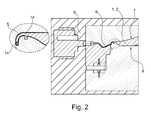
- a liquid PUR material is injected under pressure and vacuum applied at the side opposite the flow front into a gap created between the surface of the sandwich component and the surface of the RIM tool 9 - see Fig. 2 .
- the polyurethane coating material reacts by exposure to temperature (heated tool) with curing in the mold gap. This results in dependent from the tool surface, the component quality.
- the component is ready for painting after final contouring (removal of sprue and edge overhangs, surface grinding).
- a fiber composite visible component such as a hood, with tool-falling Class-A surface
- a fiber composite visible component made in PUR wet pressing method is preferably a paper honeycomb core 1 above and below with at least one layer 2 with fiber material or semi-finished fiber material, for example, from woven, laid, knitted, Mats, gratings and nonwovens of glass fiber and / or carbon fiber and / or textile materials and / or ceramic fibers and / or natural fibers and / or plastic fibers wrapped.
- the honeycomb core 1 can be performed in the required places in reinforced construction. Subsequently, the polyurethane matrix 3 application is carried out in the PUR-CSM spraying process.
- the semi-finished fiber products 2 are wetted on both sides with a thermally activatable PUR system which, applied in optimized layer thickness, produces a connection between core 1 and cover layers 2.
- a targeted matrix application in all component areas with the addition of short fiber material such as glass fiber, carbon fiber, textile fibers, is possible.
- the component is pressed and cured within a heated mold 4 according to its required component geometry.
- the trimming of the outer contour follows as the next step before in the V-RIM process on the visible side and around the outer edges of the component around the paintable Class-A surface (RIM layer 5) applied and prepared in a final finishing process (surface activation) ready for painting.
- the V-RIM method is due to the component size of visible components, for example in the automotive industry, for example, for bonnets, in relation to the layer thickness (gap between Sandwich component and RIM tool 9 between 0.2 - 2.0mm) highly advantageous.
- the PUR RIM matrix 3 is not only pressed into the gap between sandwich component and RIM tool 9 via point and / or area injection nozzles 6 but pulled the flow front over one on the opposite side to one or more points or over-surface vacuum 7 and thus enables a gap-free and process-reliable gap filling. It is important to optimize the ratio of component surface to layer thickness in the context of the component geometry, whereby the minimized component weight is the decisive influencing factor.
- This surface material for example polyurethane and / or other flowable surface materials for plastic surfaces, is cured in a tempered tool, in the temperature range between 40 ° C and 170 ° C.
- a tempered tool in the temperature range between 40 ° C and 170 ° C.
- Targeted control of the parameters Mixing ratio matrix material, viscosity and mold temperature allows curing times of less than 5 minutes.
- the tool is divided into temperature zones. These are independent of each other and the component geometry to temper accordingly, ie to heat and / or to cool.
- an additional tempering process after curing / cooling or after V-RIM application can be integrated to increase the temperature stability of the component, especially for in-line and online paint resistance.
- This tempering process can be up to 210 ° C and max. Take 60 minutes, either in a heated tool, oven or in a continuous furnace.
- the surface layer should not be thinner than 0.2 mm and not thicker than 2.0 mm.
- the tool can be designed for a better surface thickness adjustment by means of dipping edge technology.
- the surface material fills the gap between the cut (also milled, lasered, stamped or similarly prefabricated) structural component and the tool surface.
- the thickness of the surface layer may be significantly greater and may also be a few millimeters - see Fig. 2 and Fig. 3 ,
- the component is inserted and positioned manually or automatically in the tool, namely preferably centered over the component mold or by means of an RPS system, and held by means of vacuum suction on the opposite component surface and / or by means of closing and fixing aids.
- the tool has one or more point fences or a fan gate to distribute the surface material bubble-free over the component surface and according to the selected layer thickness. Furthermore, venting or vacuum components are provided in the tool to extract the air from the tool during injection or to be able to keep the injection pressure as low as possible.
- the position of the sprue or the venting blocks depends on the component shape as well as the tool and the selected system concept (tilt and swivel tool).
- the venting and / or vacuum components are closed in order to ensure process-reliable and bubble-free surface and edge filling.
- the time depends on several parameters, such as temperature of the tool, component and / or matrix, duration of the filling process, filling volume (parameterized) and filling pressure.
- the tool After curing, the tool is opened and the component removed. Depending on the size of the component and the shape, ejectors can be used in the tool be integrated to ensure a damage-free and easy removal.
- the degree of the component due to the parting plane can then be manually or mechanically trimmed or ground off.
- the component is ready for the further process steps (preparation for painting).
- the entire process preferably proceeds within the cycle time of 280 seconds, wherein the application of the surface layer (RIM layer 5) to achieve the CLASS-A surface preferably takes place exclusively in the later field of vision of the component and around component edges.
- the sealing of the edges serves to seal the components as well as to improve the haptic impression.
- the V-RIM process is preferably carried out as a parallel process step for sandwich production.
- a suitable PUR material which can be processed in the V-RIM process and ensures the required surface quality is available, for example, from Rühl Puromer GmbH.
- a sandwich component according to the invention can also be used for functional integration and in particular realize the functions antenna function, lighting, energy storage function, air supply and - line in the engine compartment. Further functional integration can also result with regard to optical effects such as direct and indirect illumination, which on the one hand can be designed as a safety function, on the other hand can emphasize contours and structures on the vehicle as a design-supporting element.
- Fig. 3 a sectional drawing is shown, showing an inventive, finished, crimped sandwich component.
- the component comprises a honeycomb core 1, two cover layers 2, wherein the honeycombs of the honeycomb core 1 are particularly heavily crimped or molded, especially in a first zone 12, are less pressed in a second zone 13 and form a course to the zone 12.
- the component also has a RIM layer 5 and an edge seal as RIM layer 5 on the end face 11 of the component.
- the gasket 14 shown in FIG Fig. 2
- the shape of the end of the RIM layer 5 can be determined.
- seal 14 square sealing cross section of the seal 14 is on the underside of the sandwich component, a corresponding transition of the RIM layer 5 a - of course, the shape of the tool is relevant.
- seal shapes of the seal 14 and / or other tool shape By means of other seal shapes of the seal 14 and / or other tool shape, a different course or runout of the RIM layer 5 or another transition of the RIM layer 5 to the cover layer 2 would be possible.
Landscapes
- Engineering & Computer Science (AREA)
- Mechanical Engineering (AREA)
- Physics & Mathematics (AREA)
- Thermal Sciences (AREA)
- Oral & Maxillofacial Surgery (AREA)
- Health & Medical Sciences (AREA)
- Manufacturing & Machinery (AREA)
- Composite Materials (AREA)
- Chemical & Material Sciences (AREA)
- Fluid Mechanics (AREA)
- Architecture (AREA)
- Civil Engineering (AREA)
- Structural Engineering (AREA)
- Casting Or Compression Moulding Of Plastics Or The Like (AREA)
- Laminated Bodies (AREA)
- Injection Moulding Of Plastics Or The Like (AREA)
- Moulding By Coating Moulds (AREA)
- External Artificial Organs (AREA)
- Moulds For Moulding Plastics Or The Like (AREA)
Abstract
Description
- Die vorliegende Erfindung betrifft ein Verfahren zur Herstellung eines Sandwichbauteiles sowie eine Vorrichtung zur Herstellung eines Sandwichbauteiles und ein Sandwichbauteil.
- Sandwichbauteile sind typischerweise flächige Bauteile die aus zumindest drei Lagen aufgebaut sind, nämlich einer zentralen Kernlage zwischen zwei Deckschichten oder Decklagen und werden beispielsweise im Automobilbau als Karosseriebauteile eingesetzt, insbesondere für den Automobilbau in Leichtbauweise. Meist werden flächige Sandwichbauteile erzeugt, deren Form in einer Formpresse angepasst werden kann.
- Aus der
DE 10 2010 0054 56 A1 ist beispielsweise ein Sandwichbauteil bekannt, umfassend einen Wabenkern mit einer Vielzahl von Stegen und zumindest einer Deckschicht, wobei der Wabenkern aus einem auf Zellulose basierten Material, insbesondere Papier besteht, wobei die Deckschicht aus einem Faser verstärkten Halbzeug mit einer thermoplastischen Kunststoffmatrix gebildet wird, wobei die Stege des Wabenkerns an Anschlussstellen zu der Deckschicht wenigstens teilweise in die thermoplastische Kunststoffmatrix der Deckschicht aufgenommen sind, so dass ein Verbund des Sandwichbauteils bereitgestellt wird. - Aus der
DE 10 2012 006 609 A1 ist ein Sandwichbauteil bekannt, mit zwei faserverstärkten thermoplastischen Deckschichten und einer dazwischen angeordneten Wabenkernlage, wobei die Deckschichten mittels eines thermoplastischen Materials mit der Wabenkernlage verbunden ist, und wobei zumindest eine Seite des Sandwichbauteils eine Dekorlage aufweist, die auf der Deckschicht angeordnet ist, wobei das Sandwichbauteil ferner zumindest eine Schaumlage umfasst, die zwischen der Deckschicht und der Dekorlage angeordnet ist, wobei die Schaumlage mit der Deckschicht und der Dekorlage verbunden ist. Durch diese Lösung soll ein kaschiertes Sandwichbauteil geschaffen werden, dass durch den verwendeten Stützkern entstehende Oberflächenfehler an der Dekorlage vermeiden soll. - Es ist eine Aufgabe der Erfindung, ein Verfahren zur Herstellung eines Sandwichbauteiles anzugeben, dass erlaubt ein Sandwichbauteil mit einer Class-A Oberfläche ohne aufwändige Nachbearbeitung der sichtbaren Oberfläche des Sandwichbauteils herzustellen, sowie eine entsprechende Vorrichtung zur Herstellung eines Sandwichbauteiles. Eine weitere Aufgabe der Erfindung ist es ein einfach herzustellendes Sandwichbauteil anzugeben dass eine Class-A Oberfläche aufweist.
- Die Lösung der Aufgabe erfolgt durch ein Verfahren zur Herstellung eines Sandwichbauteiles, umfassend die Schritte dass
- ein Wabenkern mit einer Vielzahl an Stegen beidseitig mit zumindest einer Lage eines Fasermaterials, welche Decklagen bilden, belegt oder ummantelt wird,
- das Paket aus Wabenkern und Faserlagen mit einer Matrix getränkt, benetzt oder besprüht wird,
- das Paket in ein Formpresswerkzeug gelegt und entsprechend der geforderten Bauteilgeometrie zu einem Bauteil verpresst wird und aushärtet,
- zumindest auf eine Sichtseite des Bauteils anschließend eine Class-A Oberfläche als RIM-Schicht in einem Reaction Injection Molding (RIM) Verfahren, insbesondere einem Vakuum Reaction Injection Molding Verfahren (V-RIM), aufgebracht wird.
- Unter "Class-A Oberfläche" wird erfindungsgemäß verstanden, dass Unebenheiten, insbesondere Welligkeiten auf Grund der stirnseitigen Kanten des Wabenkernes an der Oberfläche des Bauteiles soweit vermieden sind, dass eine Lackierung des Bauteils ohne nachträglicher Entfernung solcher Unebenheiten möglich ist, also die Oberfläche ausreichend hohe Krümmungsstetigkeit aufweist, somit ausreichend glatt ist, um als sichtbare Oberfläche beispielsweise einer Automobilkarosserie verwendet werden zu können. Außer einer eventuellen Oberflächenaktivierung und nachfolgenden Lackiervorgängen ist daher keine Nachbearbeitung im üblichen Sinn, der beschriebenen Beseitigung von Welligkeiten, erforderlich.
- Die Lösung der Aufgabe erfolgt auch durch eine Vorrichtung die zur Durchführung eines solchen Verfahrens ausgelegt ist. Die Vorrichtung umfasst dazu ein RIM Werkzeug, wobei das RIM Werkzeug bevorzugt beheizbar, insbesondere zonenbeheizbar ist, so dass verschiedene Zonen des Sandwichbauteils verschieden stark geheizt werden können.
- Die Lösung der Aufgabe erfolgt auch durch ein Sandwichbauteil das einen Wabenkern mit einer Vielzahl an Stegen umfasst der beidseitig mit zumindest einer Lage eines Fasermaterials, welche Decklagen bilden, belegt oder ummantelt ist, wobei die Faserlagen mit einer Matrix getränkt, benetzt oder besprüht sind, wobei das Bauteil formgepresst ist und wobei zumindest auf einer Sichtseite des Bauteils eine lackierfähige Class-A Oberfläche in einem Reaction Injection Molding Verfahren aufgebracht ist.
- Ein erfindungsgemäßes Verfahren zur Herstellung eines Faserverbund-Sandwichbauteiles, umfasst bevorzugt, dass ein Wabenkern mit einer Vielzahl von Stegen, beidseitig, insbesondere oben und unten, mit zumindest einer Lage eines Fasermaterials, beispielsweise eines Faserhalbzeuges, als Deckschichten bzw. Decklagen belegt oder ummantelt wird. Hierbei kann das Fasermaterial bereits eine Matrix enthalten.
- Anschließend wird der das Paket ("composite package") aus Wabenkern und Decklagen mit einer Matrix, vorzugsweise Polyurethan - PUR, getränkt, benetzt und /oder besprüht, vorzugsweise im CSM Sprühverfahren.
- Als Matrix bzw. Matrixmaterial kommen bevorzugt thermoplastische oder besonders bevorzugt duroplastische Kunststoffe zur Anwendung.
- Anschließend wird das mit Matrix beaufschlagte Paket in ein Formpresswerkzeug, vorzugsweise ein beheiztes Formpresswerkzeug, gelegt und entsprechend der geforderten Bauteilgeometrie verpresst und ausgehärtet.
- Anschließen kann optional während das Bauteil im Formpresswerkzeug belassen wird, rund um das Werkzeug bzw. rund um die Werkzeuggeometrie ein "contur cut", also ein grober Zuschnitt durchgeführt werden.
- Anschließend kann optional das Bauteil bedarfsweise im Formpresswerkzeug oder außerhalb des Formpresswerkzeugs gekühlt bzw. thermisch stabilisiert werden, bevorzugt in einem weiteren Werkzeug, insbesondere in einer Werkstückkühlvorrichtung, gekühlt bzw. thermisch stabilisiert werden. Unter "thermisch stabilisiert" wird dabei verstanden, dass das Bauteil eine Temperatur unter der letzten Umwandlungstemperatur einnimmt um einen stabilen Zustand zu erreichen. Das Kühlen in einer Werkstückkühlvorrichtung erlaubt dabei, insbesondere im Hinblick auf eine durchgehende Produktion nur eines Bauteiles, die kürzeste Produktionszeit.
- Optional erfolgt ein Tempern des Bauteils, also ein Temperaturprozess, damit sich Bauteilverzüge ausgleichen bzw. sich der Vernetzungsgrad der Materialien erhöht, in einem weiteren Werkzeug oder einer weiteren Vorrichtung. Beispielsweise kann das Bauteil zum Abkühlen nur auf einen Rahmen oder einseitig auf eine Fläche gelegt werden. Es kann aber auch eine geschlossene Kühlvorrichtung verwendet werden, die das Bauteil vollumfänglich umschließt und in welchem die Temperatur geregelt werden kann.
- Optionales erfolgt noch ein (nochmaliges) Kühlen des Bauteiles.
- Hierauf erfolgt bevorzugt ein Beschnitt der Außenkontur bzw. Zuschnitt der Seitenbereiche/Kanten entsprechend der geforderten Bauteilkontur sowie optional auch eine spannabhebende Bearbeitung, wie beispielsweise Fräsen der Außenkontur sowie Fräsen und Bohrungen für Inserts und ähnliche andere Ausnehmungen im Bauteil.
- Es erfolgt das Aufbringen der lackierfähigen Class-A Oberfläche (Oberflächenauftrag bzw. RIM-Schicht) auf der Sichtseite und /oder um die Außenkanten, vorzugsweise im V-RIM (Vakuum-RIM)Verfahren in einem weiteren Werkzeug. Hierdurch wird erreicht, dass keine sonst übliche störende Welligkeit an der Oberfläche des Bauteils verbleibt.
- Optional kann an dieser Stelle (nochmals) ein Tempern erfolgen.
- Optional kann eine lackierfertige Aufbereitung der so hergestellten Oberflächen durch Oberflächenaktivierung in einem finalen Finishing-Verfahren erfolgen.
- Optional können abschließend Inserts in das Bauteil eingesetzt werden.
- Das Bauteil kann anschließend lackiert werden.
- Der Wabenkern bzw. der mit Deckschichten belegte oder ummantelte Wabenkern kann mittels Spannrahmen gehalten werden, sodass dieser gedreht und gewendet werden kann, um problemlos einen Sprühauftrag oder ein Benetzen mit einem Matrixmaterial durchzuführen.
- Der Wabenkern kann an erforderlichen Stellen, zum Beispiel zur Verstärkung in einem späteren Scharnieraufnahmebereich, in verstärkter Bauweise ausgeführt sein kann, um unterschiedliche Stauchhärten, zum Beispiel für den Fußgängerschutz, sowie gewünschte Stabilitäten zu erreichen.
- Der Matrixaufbau kann unstetig erfolgen bzw. je nach Bauteilerfordernissen partiell unterschiedlich sein, insbesondere kann Zonenweise eine zusätzliche Zugabe von Kurzfasermaterial (Glas-, Kohle-, Textilfasern etc.) erfolgen, insbesondere so, dass je nach Bauteilerfordernissen partiell unterschiedliche Eigenschaften des Bauteils in verschiedenen über die Fläche des Bauteils sich erstreckenden Zonen entstehen.
- Der Matrixaufbau des Sandwichbauteiles kann bewirken, dass eine klebende Verbindung zwischen Wabenkern und Decklagen hergestellt wird.
- Bevorzugt erfolgt das Formpressen während das Paket bzw. die auf den Decklagen befindliche Matrix noch nass ist.
- Das Aufbringen der lackierfähigen Class-A Oberfläche erfolgt bevorzugt mittels Injizieren von Matrix Füllmaterial, vorzugsweise PUR, mit Drücken unter 20 bar und/oder unter Zuhilfenahme eines Vakuums in einem dem Injektionsbereich gegenüberliegenden Bereich in einem geschlossenen und /oder beheizten und /oder zonenbeheizten Werkzeug. Ein zonenbeheiztes Werkzeug ermöglicht sowohl dass der Matrixauftrag auf die Deckschichten unterschiedlich dick sein kann, als auch dass über die Fläche des Bauteiles verteilt nicht immer die gleiche Anzahl oder gleichartige Wabenkerne übereinandergeschichtet verwendet werden müssen. Erfindungsgemäß können zum Beispiel in einem mittleren Bereich des Bauteils 2-3 Wabenkerne übereinander geschichtet und in einem Randbereich nur 1 oder 2 Wabenkerne übereinander geschichtet sein, um das Bauteil an jeweilige Funktionsanforderungen, beispielsweise an einen optimalen Fußgängerschutz bzw. Kopfaufprallschutz, individuell anpassen zu können. Daher kann im Bauteil je nach Dicke bzw. unterschiedlichem Aufbau ein unterschiedlicher Wärmebedarf für das Aufbringen der Class-A Oberfläche und somit ein zonenbeheiztes Werkzeug erforderliche sein.
- Die Matrix wird bevorzugt in einen Spalt zwischen Sandwichbauteil und RIM-Werkzeug über mindestens eine punktförmige und / oder mindestens eine Flächeneinspritzdüse gedrückt. Besonders bevorzugt wird die Fließfront bzw. der Matrixfluss über ein an der gegenüberliegenden Seite an ein oder mehreren Punkte bzw. Bereichen flächig angelegtes Vakuum gezogen. Hierdurch wird eine lückenlose, über eine große Fläche gehende, kontinuierliche Spaltfüllung ermöglicht.
- Im Gegensatz zu einem üblichen sehr dünnen Aufbringen von RIM-Schichten, insbesondere unter 0,01 mm, was ein vorzeitiges Erstarren der Matrix bewirkt, wird in der erfindungsgemäßen Lösung bevorzugt ein zusätzliches Vakuum verwendet und hierdurch eine wesentlich dickere RIM-Schicht, also Matrix-Schicht, von ca. 0,2 - 2 mm erzeugt und dadurch sichergestellt, dass das Material nicht vorzeitig erstarrt und sich eine gleichmäßige Schicht bildet.
- Die mindestens eine punktförmige und / oder mindestens eine Flächeneinspritzdüse, also der Anguss, liegt bevorzugt einerseits zwischen den beiden Werkzeugen bzw. Werkzeughälften und andererseits im Kantenbereich des Sandwichbauteils, damit das Bauteil auf der Unterseite und auf der Oberseite gleichmäßig umströmt wird.
- Im Werkzeug sind bevorzugt zusätzlich Entlüftungs- und/oder Vakuumbausteine vorgesehen, um beim Injizieren die Luft aus dem Werkzeug zu extrahieren bzw. den Injizierungsdruck so gering wie möglich zu halten.
- Bevorzugt ist an der Nicht-Sichtseite des Bauteils eine Dichtung angeordnet, die verhindert, dass sich die RIM-Schicht auf die Nicht-Sichtseite, bevorzugt die Unterseite des Bauteils, verteilt, und die zwei separate Vakuumbereiche voneinander trennt.
- Durch die Formgebung der Dichtung wird die Form des Endes der RIM-Schicht bestimmt. Durch die Formgebung der Dichtung kann bevorzugt beispielsweise ein kontinuierlicher Übergang zwischen Oberseite der RIM-Schicht und Deckschicht eingestellt werden.
- Das Class-A Oberflächenmaterial, also die RIM-Schicht, versiegelt bevorzugt die Beschnittkanten des Bauteils, vorzugsweise an den Seitenbereichen und /oder Kantenbereichen des Bauteils und/oder die Stirnseiten des Wabenkernes. Bevorzugt werden an den seitlichen Enden des Sandwichbauteils die beiden Deckschichten mittels der RIM-Schicht verbunden also verschlossen.
- Das Faserverbund-Sandwichbauteil kann während des V-RIM Oberflächenauftrages über ein Vakuum-Spannsystem gehalten werden, insbesondere im Unterteil der Aufnahme gehalten werden.
- Nach dem V-RIM Oberflächenauftrag kann die Oberfläche des Bauteiles zu glatt sein, so dass die Oberfläche aus Lackhaftungsgründen wieder aufgeraut werden muss bzw. in einem finalen Finishing-Verfahren, beispielsweise durch Schleifen, einen Plasmaprozess oder Chemisch aktiviert werden muss.
- Bevorzugt wird das Faserverbund-Sandwichbauteil während des RIM-Oberflächenauftrages mittels eines Faserverbund-Referenzpunktsystems positioniert.
- Das Matrixmaterial der Deckschichten als auch der RIM-Schicht ist vorzugsweise ein duroplastischer Kunststoff, bevorzugter PUR, wobei die Deckschichten und die RIM-Schicht nicht das gleiche Matrixmaterial, insbesondere nicht das gleiche PUR Material verwenden müssen.
- Die Erfindung wird im Folgenden beispielhaft unter Bezugnahme auf die Zeichnungen beschrieben.
- Fig. 1
- zeigt Schritte in einem erfindungsgemäßen Verfahren zur Herstellung eines Sandwichbauteiles.
- Fig. 2
- zeigt eine Vorrichtung zur Durchführung eines Schrittes in einem erfindungsgemäßen Verfahren zur Herstellung eines Sandwichbauteiles, nämlich ein RIM-Werkzeug (rechts), sowie eine Detailansicht dazu (links).
- Fig. 3
- zeigt ein erfindungsgemäßes Sandwichbauteil.
- In
Fig. 1 sind, teilweise optionale, Schritte S1 bis S7 in einem erfindungsgemäßen Verfahren zur Herstellung eines Sandwichbauteiles dargestellt. - Ein erfindungsgemäßes Verfahren zur Herstellung eines Faserverbund-Sandwichbauteiles, umfasst bevorzugt dass ein Wabenkern 1 mit einer Vielzahl von Stegen, oben und unten mit zumindest einer Lage eines Fasermaterials 2, beispielsweise eines Faserhalbzeuges, als Deckschichten bzw. Decklagen belegt oder ummantelt wird (Schritt 1, S1).
- Die Kerne bzw. Wabenkerne sind vorzugsweise Papierkerne, Kartonkerne oder bestehen aus anderen, auf Zellulose basierten Materialien, können aber auch Kerne aus Kunststoff, wie Polyurethan (PU), Polypropylen (PP) und ähnliches oder aus Metall, Holz oder Schaummaterial sein.
- Die Wabenkerne können Stege in bienenwabenförmiger Anordnung aufweisen oder in wellenförmiger Anordnung. Die Stege können jedoch auch runde, dreieckige, rechteckige, quadratische, trapezförmige oder vieleckige Zellen ausbilden, wobei es sich hierbei (innerhalb eines Wabenkernes) nicht um regelmäßig wiederkehrende Formen handeln muss.
- Anschließend wird der das Paket("composite package") aus Wabenkern 1 und Decklagen 2 mit einer Matrix 3, vorzugsweise PUR, getränkt, benetzt und /oder besprüht, vorzugsweise im CSM Sprühverfahren (Schritt 2, S2).
- Anschließend wird das mit Matrix 3 beaufschlagte Paket in ein Formpresswerkzeug 4, vorzugsweise ein beheiztes Formpresswerkzeug, gelegt und entsprechend der geforderten Bauteilgeometrie verpresst und ausgehärtet (Schritt 3, S3).
- Optional kann während das Bauteil im Werkzeug belassen wird, rund um das Werkzeug bzw. rund um die Werkzeuggeometrie ein "contur cut", also ein grober Zuschnitt durchgeführt werden.
- Anschließend kann opional das Bauteil bedarfsweise im Formpresswerkzeug 4 oder außerhalb des Formpresswerkzeuges gekühlt werden, insbesondere in einem weiteren Werkzeug, wie in einer Werkstückkühlvorrichtung 10, gekühlt bzw. thermisch stabilisiert werden (Schritt 4, S4).
- Optional erfolgt ein Tempern des Bauteils, also ein Temperaturprozess über längere Zeit, damit sich Bauteilverzüge ausgleichen bzw. sich der Vernetzungsgrad der Materialien erhöht, in einem weiteren Werkzeug oder einer weiteren Vorrichtung.
- Optionales erfolgt noch ein (nochmaliges) Kühlen des Bauteiles.
- Hierauf erfolgt bevorzugt ein Beschnitt der Außenkontur bzw. Zuschnitt der Seitenbereiche/Kanten entsprechend der geforderten Bauteilkontur sowie optional auch spannabhebende Bearbeitung, wie beispielsweise Fräsen der Außenkontur sowie Fräsen und Bohrungen für Inserts und ähnliche andere Ausnehmungen im Bauteil (Schritt 5, S5).
- Es erfolgt das Aufbringen der lackierfähige Class-A Oberfläche, also ein Oberflächenauftrag als RIM-Schicht 5 auf der Sichtseite und /oder um die Außenkanten, vorzugsweise in einem V-RIM Verfahren, also bei Verwendung eines Vakuums zum Ansaugen der eingebrachten Matrix 3, in einem RIM-Werkzeug 9 (Schritt 6, S6). Hierdurch wird erreicht, dass keine sonst übliche störende Welligkeit, Lunkerbildungen oder Poren an der sichtbaren Oberfläche des Bauteils verbleibt.
- Optional kann an dieser Stelle (nochmals) ein Tempern erfolgen.
- Optional kann eine lackierfertige Aufbereitung der so hergestellten Oberflächen durch Oberflächenaktivierung in einem finalen Finishing-Verfahren erfolgen (Schritt 7, S7).
- Optional können Inserts in das Bauteil eingesetzt werden (Schritt 7, S7).
- Beim Vakuum - Reaction Injection Molding (V-RIM) erfolgt ein Injizieren eines flüssigen PUR Materials unter Druck und unter Aufbringung eines Vakuums an der der Fließfront gegenüberliegenden Seite in einen zwischen der Oberfläche des Sandwichbauteiles und der Oberfläche des RIM Werkzeuges 9 erzeugten Spalt - siehe
Fig. 2 . Das Polyurethan-Überzugsmaterial reagiert dabei durch Einwirken von Temperatur (beheiztes Werkzeug) mit Aushärtung im Werkzeugspalt. Dabei ergibt sich abhängig von der Werkzeugoberfläche die Bauteilqualität. Das Bauteil ist nach der finalen Konturbearbeitung (entfernen von Anguss und Kantenüberständen, Oberfläche anschleifen) lackierbereit. - Für die Herstellung eines Faserverbund Sichtbauteiles, wie zum Beispiel einer Motorhaube, mit werkzeugfallender Class-A Oberfläche, gefertigt im PUR-Nasspressverfahren wird bevorzugt ein Papierwabenkern 1 oben und unten mit zumindest einem Layer 2 mit Fasermaterial oder Faserhalbzeugmaterial beispielsweise aus Geweben, Gelegen, Gestricken, Matten, Gittern und Vliesen aus Glasfaser und / oder Kohlefaser und / oder textilen Materialien und / oder Keramikfasern und / oder Naturfasern und / oder Kunststofffasern umhüllt. Um die unterschiedlichen Stauchhärten sowie die Stabilität, beispielsweise im Scharnierbereich zu erreichen, kann der Wabenkern 1 an den erforderlichen Stellen in verstärkter Bauweise ausgeführt werden. Im Anschluss erfolgt der Polyurethan Matrix 3 Auftrag im PUR-CSM Sprühverfahren. Bei diesem Sprühauftrag werden die Faserhalbzeuge 2 beidseitig mit einem thermisch aktivierbaren PUR-System benetzt das in optimierter Schichtstärke aufgebracht eine Verbindung zwischen Kern 1 und Decklagen 2 herstellt. Hierbei ist auch ein gezielter Matrixauftrag in sämtlichen Bauteilbereichen unter Zugabe von Kurzfasermaterial wie Glasfaser, Kohlefaser, textile Fasern, möglich. Im folgenden Prozessschritt wird das Bauteil innerhalb einer beheizten Form 4 entsprechend seiner geforderten Bauteilgeometrie verpresst und ausgehärtet. Der Beschnitt der Außenkontur folgt als nächster Schritt bevor im V-RIM Verfahren auf der Sichtseite und um die Außenkanten des Bauteiles herum die lackierfähige Class-A Oberfläche (RIM-Schicht 5) aufgebracht und in einem finalen Finishing Verfahren (Oberflächenaktivierung) lackierfertig aufbereitet wird. Das V-RIM Verfahren ist auf Grund der Bauteilgröße von Sichtbauteilen, zum Beispiel in der Automobilindustrie beispielsweise für Motorhauben, im Verhältnis zur Schichtdicke (Spalt zwischen Sandwichbauteil und RIM Werkzeug 9 zwischen 0,2 - 2,0mm) höchst vorteilhaft. Dabei wird die PUR RIM Matrix 3 nicht nur in den Spalt zwischen Sandwichbauteil und RIM Werkzeug 9 über Punkt- und/ oder Flächeneinspritzdüsen 6 gedrückt sondern die Fließfront über ein an der gegenüberliegenden Seite an ein oder mehreren Punkten bzw. über flächig angelegtem Vakuum 7 gezogen und ermöglicht somit eine lückenlose und prozesssichere Spaltfüllung. Es gilt das Verhältnis von Bauteiloberfläche zu Schichtdicke im Kontext zur Bauteilgeometrie zu optimieren, wobei das minimierte Bauteil-Gesamtgewicht den entscheidenden Einflussfaktor bildet. Herkömmliche Spaltfüllsysteme haben den Nachteil, dass ab Verhältnissen von Oberflächen zu Schichtdicke von unter 0,01 das Erstarren der Fließfront noch vor der vollständigen Spaltfüllung erfolgt. Auch PUR Systeme mit herkömmlicher Aushärteverzögerung sind nicht in der Lage die geforderte Offenzeit bei gleichzeitigem Anspruch auf die werkzeugfallende CLASS-A Oberflächenqualität zu gewährleisten - sie neigen verstärkt zu Blasenbildung im Klimawechseltest bedingt durch einen Aktivator. Das Sandwichbauteil selbst wird während des V-RIM Oberflächenauftrages über ein Vakuum Spannsystem bzw. über flächig angelegtem Vakuum 8 im Unterteil der Aufnahme gehalten und über ein Faserverbund RPS System positioniert. Hierbei ist das Vakuum 7 vom Vakuum 8 beispielsweise durch eine Dichtung 14 getrennt, sodass die zur Erfüllung der jeweiligen unterschiedlichen Funktion, wie beispielsweise ziehen der Matrix oder Festhalten des Sandwichbauteiles an der Aufnahme bzw. am Werkzeug, nötigen unterschiedlichen Vakuum-Drücke einstellbar sind.
- Um bei Sandwichbauteilen, die eine relativ geringe beschädigungsresistente Druckfestigkeit besitzen, eine CLASS-A Oberfläche sowie eine Versiegelung der Beschnittkanten zu erhalten, bedarf es einer Oberflächen- Applikation mittels Injizieren von Matrix Füllmaterial mit Drücken unter 20 bar und/oder unter Zuhilfenahme eines Vakuums in einem dem Injektionsbereich gegenüberliegenden Bereich in einem geschlossenen und/oder beheizten/zonenbeheizten Werkzeug (
Fig. 2 ). - Dieses Oberflächenmaterial, zum Beispiel Polyurethan und/oder andere fließfähige Oberflächenmaterialien für Kunststoffoberflächen, wird in einem temperierten Werkzeug, im Temperaturbereich zwischen 40°C und 170°C, ausgehärtet. Durch gezielte Steuerung der Parameter Mischungsverhältnis-Matrixmaterial, Viskosität und Werkzeugtemperatur können Aushärtezeiten von unter 5 Minuten erreicht werden. Um den Aushärteprozess homogener gestalten und kontrolliert Wärme einbringen zu können wird das Werkzeug in Temperaturzonen eingeteilt. Diese sind unabhängig voneinander und der Bauteilgeometrie entsprechend zu temperieren, also zu heizen und/oder zu kühlen. Zusätzlich kann ein zusätzlicher Temperprozess nach der Aushärtung / Abkühlung bzw. nach der V-RIM Applizierung integriert werden, um die Temperaturstabilität des Bauteils, vor allem für eine Inline- und Online-Lackierbeständigkeit zu erhöhen. Dieser Temperprozess kann bis zu 210°C betragen und max. 60min dauern, entweder in einem beheizten Werkzeug, Ofen oder in einen Durchlaufofen.
- Um eine dauerhafte anspruchsvolle Oberfläche zu gewährleisten darf die Oberflächenschicht nicht dünner als 0,2 mm und nicht dicker als 2,0 mm sein. Das Werkzeug kann für eine bessere Oberflächen-Dickeneinstellung mittels Tauchkantentechnologie ausgelegt sein.
- Im Kantenbereich füllt das Oberflächenmaterial den Spalt zwischen den beschnittenen (auch gefrästen, gelaserten, gestanzten oder ähnlich vorkonfektionierten) Strukturbauteil und der Werkzeugoberfläche auf. Dabei kann die Dicke der Oberflächenschicht wesentlich größer sein und auch einige Millimeter betragen - siehe
Fig. 2 undFig. 3 . - Das Bauteil wird in das Werkzeug händisch oder automatisiert eingelegt und positioniert, nämlich bevorzugt über die Bauteilform oder mittels eines RPS-Systems zentriert, und mittels Vakuumansaugung an der gegenüberliegenden Bauteilfläche und/oder mittels Zuzieh- und Fixierungshilfen gehalten.
- Das Werkzeug hat einen oder mehrere Punktangusse oder einen Fächeranguss, um das Oberflächenmaterial blasenfrei über die Bauteiloberfläche und entsprechend der gewählten Schichtdicke zu verteilen. Weiters sind im Werkzeug Entlüftungs- oder Vakuumbausteine vorgesehen um beim Injizieren die Luft aus dem Werkzeug zu extrahieren bzw. den Injizierungsdruck so gering wie möglich halten zu können. Die Position des Angusses bzw. der Entlüftungsbausteine ist abhängig von der Bauteilform sowie dem Werkzeug und dem gewählten Anlagenkonzept (Kipp- und Schwenkwerkzeug).
- Unmittelbar vor Beendigung der Werkzeug - Bauteil Spaltfüllung (abhängig vom zu befüllenden Werkzeug bzw. der Bauteilform) werden die Entlüftungs- und/oder Vakuumbausteine geschlossen um die prozesssichere und blasenfreie Oberflächen- und Kantenfüllung sicher zu stellen. Der Zeitpunkt ist von mehreren Parametern, wie Temperatur von Werkzeug, Bauteil und/oder Matrix, Dauer des Befüllvorganges, Füllvolumen (parametrisiert) und Fülldruck abhängig.
- Nach Aushärtung wird das Werkzeug geöffnet und das Bauteil entnommen. Je nach Bauteilgröße und Form können im Werkzeug Auswerfer integriert sein die eine beschädigungsfreie und einfache Entnahme gewährleisten.
- Der Grad am Bauteil bedingt durch die Werkzeugtrennebene kann im Anschluss händisch oder maschinell beschnitten oder abgeschliffen werden.
- Das Bauteil ist für die weiteren Prozessschritte (Vorbereitung zur Lackierung) bereit.
- Der gesamte Prozess läuft bevorzugt innerhalb der Taktzeit von 280 Sekunden ab, wobei das Aufbringen der Oberflächenschicht (RIM-Schicht 5) zur Erreichung der CLASS-A Oberfläche bevorzugt ausschließlich im späteren Sichtbereich des Bauteiles und um Bauteilkanten herum erfolgt. Das Versiegeln der Kanten dient der Bauteilabdichtung sowie der Verbesserung des haptischen Eindruckes. Der V-RIM Prozess wird bevorzugt als paralleler Prozessschritt zur Sandwichherstellung durchgeführt.
- Ein geeignetes PUR Material, das im V-RIM Verfahren verarbeitet werden kann und die geforderte Oberflächengüte sicherstellt, ist beispielsweise von der Firma Rühl Puromer GmbH erhältlich.
- Ein erfindungsgemäßes Sandwichbauteil kann auch zur Funktionsintegration genutzt werden und insbesondere die Funktionen Antennenfunktion, Beleuchtung, Energiespeicherfunktion, Luftzuführung und - leitung im Motorraum realisieren. Weitere Funktionsintegration kann sich auch bezüglich optischer Effekte wie direkte und indirekte Beleuchtung ergeben, die einerseits als Sicherheitsfunktion ausgeführt sein können, andererseits als designunterstützendes Element Konturen und Strukturen am Fahrzeug hervorheben können.
- In
Fig. 3 ist eine Schnittzeichnung dargestellt, die ein erfindungsgemäßes fertiges, gecrushtes Sandwichbauteil zeigt. Das Bauteil umfasst einen Wabenkern 1, zwei Deckschichten 2, wobei die Waben des Wabenkerns 1 vor allem in einer ersten Zone 12 besonders stark gecrusht bzw. formgepresst sind, in einer zweiten Zone 13 weniger gepresst sind und einen Verlauf zur Zone 12 bilden. Das Bauteil weist zudem eine RIM-Schicht 5 und eine Kantenversiegelung als RIM-Schicht 5 an der Stirnseite 11 des Bauteils auf. In dieserFig. 3 ist auch gut ersichtlich, dass durch die Dichtung 14 (dargestellt inFig. 2 ) die Form des Endes der RIM-Schicht 5 bestimmt werden kann. Bei beispielsweise quadratischem Dichtungsquerschnitt der Dichtung 14 stellt sich auf der Unterseite des Sandwichbauteiles ein entsprechender Übergang der RIM-Schicht 5 ein - hierbei ist natürlich auch die Formgebung des Werkzeugs maßgeblich. Mittels anderer Dichtungsformen der Dichtung 14 und /oder anderer Werkzeugform wären ein anderer Verlauf bzw. Auslauf der RIM-Schicht 5 bzw. ein anderer Übergang der RIM-Schicht 5 zur Deckschicht 2 möglich. -
- 1
- Wabenkern
- 2
- Faserlage
- 3
- Matrix
- 4
- Formpresswerkzeug
- 5
- RIM-Schicht (Reaction Injection Molding)
- 6
- Punkt- und / oder Flächeneinspritzdüse
- 7
- erstes Vakuum
- 8
- zweites Vakuum
- 9
- RIM-Werkzeug
- 10
- Werkstückkühlvorrichtung
- 11
- Stirnseite
- 12
- erste Zone
- 13
- zweite Zone
- 14
- Dichtung
Claims (21)
- Verfahren zur Herstellung eines Sandwichbauteiles,
dadurch gekennzeichnet, dass- ein Wabenkern (1) mit einer Vielzahl an Stegen beidseitig mit zumindest einer Lage eines Fasermaterials (2), welche Decklagen bilden, belegt oder ummantelt wird,- das Paket aus Wabenkern (1) und Faserlagen (2) mit einer Matrix (3) getränkt, benetzt oder besprüht wird,- das Paket in ein Formpresswerkzeug (4) gelegt und entsprechend der geforderten Bauteilgeometrie zu einem Bauteil verpresst wird und aushärtet,- zumindest auf eine Sichtseite des Bauteils anschließend eine Class-A Oberfläche als RIM-Schicht (5) in einem Reaction Injection Molding Verfahren, insbesondere einem Vakuum Reaction Injection Molding Verfahren, aufgebracht wird. - Verfahren nach Anspruch 1,
dadurch gekennzeichnet, dass das Aufbringen der lackierfähigen Oberfläche, nämlich der RIM-Schicht (5), durch Injizieren der Matrix erfolgt, bevorzugt mit einem Druck von weniger als 20 bar. - Verfahren nach Anspruch 1 bis 2,
dadurch gekennzeichnet, dass das Aufbringen der RIM-Schicht (5) über mindestens eine punktförmige Einspritzdüse und/oder mindestens eine Flächeneinspritzdüse (6) erfolgt. - Verfahren nach Anspruch 1 oder 3,
dadurch gekennzeichnet, dass das Aufbringen der RIM-Schicht (5) durch Injizieren einer Matrix (3) bei Anliegen eines Vakuums (7) in einem dem Injektionsbereich gegenüberliegenden Bereich des Bauteils erfolgt. - Verfahren nach Anspruch 1 bis 4,
dadurch gekennzeichnet, dass das Aufbringen der RIM-Schicht (5) in einem geschlossenen und/oder beheizten, insbesondere einem zonenbeheizten RIM-Werkzeug (9) erfolgt. - Verfahren nach Anspruch 1 bis 4,
dadurch gekennzeichnet, dass die RIM-Schicht (5) eine Dicke von 0,2 - 2 mm aufweist. - Verfahren nach zumindest einem der vorhergehenden Ansprüche,
dadurch gekennzeichnet, dass das Tränken, Benetzen oder Besprühen im CSM-Sprühverfahren erfolgt. - Verfahren nach zumindest einem der vorhergehenden Ansprüche,
dadurch gekennzeichnet, dass die Matrix (3) zum Tränken, Benetzen oder Besprühen eine PUR Matrix ist. - Verfahren nach zumindest einem der vorhergehenden Ansprüche,
dadurch gekennzeichnet, dass das Formpresswerkzeug (4) beheizt ist und das nach dem Formpressen das Bauteil im Formpresswerkzeug (4) oder außerhalb des Formpresswerkzeugs (4), insbesondere in einer Werkstückkühlvorrichtung (10), abgekühlt und / oder thermisch stabilisiert wird. - Verfahren nach zumindest einem der vorhergehenden Ansprüche,
dadurch gekennzeichnet, dass nach dem Formpressen das Bauteil getempert wird. - Verfahren nach zumindest einem der vorhergehenden Ansprüche,
dadurch gekennzeichnet, dass nach dem Formpressen, insbesondere im Formpresswerkzeug (4), ein grober Zuschnitt des Bauteils erfolgt, insbesondere durch spanabhebende Bearbeitung. - Verfahren nach zumindest einem der vorhergehenden Ansprüche,
dadurch gekennzeichnet, dass vor dem Aufbringen der RIM-Schicht (5) ein Beschnitt der Außenkontur des Bauteils erfolgt und/oder eine spanabhebende Bearbeitung, wie beispielsweise Fräsen und/oder Bohren des Bauteils. - Verfahren nach zumindest einem der vorhergehenden Ansprüche,
dadurch gekennzeichnet, dass nach dem Aufbringen der RIM-Schicht (5) eine Oberflächenaktivierung stattfindet und/oder anschließend das Bauteil lackiert wird. - Vorrichtung zur Durchführung eines Verfahrens nach zumindest einem der vorhergehenden Ansprüche.
- Vorrichtung nach Anspruch 14,
dadurch gekennzeichnet, dass die Vorrichtung ein RIM-Werkzeug (9) umfasst, insbesondere ein V-RIM Werkzeug, wobei das RIM-Werkzeug (9) bevorzugt beheizbar, insbesondere zonenbeheizbar ist. - Vorrichtung nach Anspruch 14 oder 15,
dadurch gekennzeichnet, dass das RIM-Werkzeug (9) zumindest eine vakuumerzeugende Vorrichtung umfasst und bevorzugt auch eine Entlüftungsvorrichtung. - Sandwichbauteil,
dadurch gekennzeichnet, dass das Sandwichbauteil nach einem der Ansprüche 1 bis 13 hergestellt ist. - Sandwichbauteil,
dadurch gekennzeichnet, dass es einen Wabenkern (1) mit einer Vielzahl an Stegen umfasst der beidseitig mit zumindest einer Lage eines Fasermaterials (2), welche Decklagen bilden, belegt oder ummantelt ist, wobei die Faserlagen (2) mit einer Matrix (3) getränkt, benetzt oder besprüht sind, wobei das Bauteil formgepresst ist und zumindest auf einer Sichtseite des Bauteils eine Class-A Oberfläche als RIM-Schicht (5) in einem Reaction Injection Molding Verfahren, insbesondere einem Vakuum Reaction Injection Molding Verfahren, aufgebracht ist. - Sandwichbauteil nach Anspruch 17 oder 18,
dadurch gekennzeichnet, dass die Matrix (3) eine klebende Verbindung zwischen dem Wabenkern (1) und den Faserlagen (2) ausbildet. - Sandwichbauteil nach Anspruch 17 bis 19,
dadurch gekennzeichnet, dass die RIM-Schicht (5) zumindest eine, bevorzugt alle, Stirnseiten (11) des Sandwichbauteils bedeckt und bevorzugt über die Stirnseite (11) des Bauteils hinaus auch die der Sichtseite gegenüberliegende Seite des Bauteils zumindest teilweise bedeckt. - Sandwichbauteil nach Anspruch 17 bis 20,
dadurch gekennzeichnet, dass das Sandwichbauteil Zonen (12, 13) mit unterschiedlicher Festigkeit aufweist, insbesondere Zonen (12, 13) mit unterschiedlich dicken Wabenkernen (1) und/oder unterschiedlich vielen übereinandergeschichteten Wabenkernen (1) und/oder Zonen mit unterschiedlich zusammengesetzter Matrix (3).
Priority Applications (12)
| Application Number | Priority Date | Filing Date | Title |
|---|---|---|---|
| PL15153433T PL3037247T3 (pl) | 2014-12-22 | 2015-02-02 | Sposób wytwarzania elementu sandwiczowego |
| EP15153433.6A EP3037247B1 (de) | 2014-12-22 | 2015-02-02 | Verfahren zur Herstellung eines Sandwichbauteiles |
| CN201510435039.0A CN105711162B (zh) | 2014-12-22 | 2015-07-22 | 用于制造夹层部件的方法和装置以及夹层部件 |
| MX2016015637A MX381883B (es) | 2014-12-22 | 2015-12-21 | Metodo y aparato para fabricar un componente de intercalacion o tipo sandwich y el componente de intercalacion o tipo sandwich. |
| KR1020167030419A KR101930609B1 (ko) | 2014-12-22 | 2015-12-21 | 샌드위치 부품을 제조하기 위한 방법 및 장치와, 샌드위치 부품 |
| RU2016141829A RU2681898C2 (ru) | 2014-12-22 | 2015-12-21 | Способ и устройство для изготовления многослойной детали и многослойная деталь |
| JP2015248723A JP2016147482A (ja) | 2014-12-22 | 2015-12-21 | サンドイッチ部品の製造並びにサンドイッチ部品のための方法及び装置 |
| BR112016024995A BR112016024995B8 (pt) | 2014-12-22 | 2015-12-21 | Método para produzir um componente de sanduíche |
| PCT/EP2015/080779 WO2016102455A1 (de) | 2014-12-22 | 2015-12-21 | Verfahren und vorrichtung zur herstellung eines sandwichbauteiles und sandwichbauteil |
| CA2915648A CA2915648C (en) | 2014-12-22 | 2015-12-22 | Method and apparatus for manufacturing a sandwich part and sandwich part |
| US14/978,891 US9950494B2 (en) | 2014-12-22 | 2015-12-22 | Method and apparatus for manufactoring a sandwich part and sandwich part |
| JP2017133445A JP6488335B2 (ja) | 2014-12-22 | 2017-07-07 | サンドイッチ部品の製造並びにサンドイッチ部品のための方法及び装置 |
Applications Claiming Priority (2)
| Application Number | Priority Date | Filing Date | Title |
|---|---|---|---|
| EP14199859 | 2014-12-22 | ||
| EP15153433.6A EP3037247B1 (de) | 2014-12-22 | 2015-02-02 | Verfahren zur Herstellung eines Sandwichbauteiles |
Publications (2)
| Publication Number | Publication Date |
|---|---|
| EP3037247A1 true EP3037247A1 (de) | 2016-06-29 |
| EP3037247B1 EP3037247B1 (de) | 2018-01-31 |
Family
ID=52278426
Family Applications (1)
| Application Number | Title | Priority Date | Filing Date |
|---|---|---|---|
| EP15153433.6A Active EP3037247B1 (de) | 2014-12-22 | 2015-02-02 | Verfahren zur Herstellung eines Sandwichbauteiles |
Country Status (12)
| Country | Link |
|---|---|
| US (1) | US9950494B2 (de) |
| EP (1) | EP3037247B1 (de) |
| JP (2) | JP2016147482A (de) |
| KR (1) | KR101930609B1 (de) |
| CN (1) | CN105711162B (de) |
| BR (1) | BR112016024995B8 (de) |
| CA (1) | CA2915648C (de) |
| ES (1) | ES2662398T3 (de) |
| MX (1) | MX381883B (de) |
| PL (1) | PL3037247T3 (de) |
| RU (1) | RU2681898C2 (de) |
| WO (1) | WO2016102455A1 (de) |
Cited By (1)
| Publication number | Priority date | Publication date | Assignee | Title |
|---|---|---|---|---|
| DE102018133115A1 (de) | 2017-12-22 | 2019-06-27 | Engel Austria Gmbh | Injektionssystem |
Families Citing this family (16)
| Publication number | Priority date | Publication date | Assignee | Title |
|---|---|---|---|---|
| CN106436459B (zh) * | 2016-11-25 | 2017-12-05 | 嘉善泰力蜂窝制品有限公司 | 一种诺梅克斯蜂窝芯生产用芳纶纸浸渍装置 |
| DE102017008097B4 (de) * | 2017-08-29 | 2019-06-27 | Webasto SE | Fahrzeug-Sandwichbauteil und Verfahren zum Herstellen eines Fahrzeug-Sandwichbauteils |
| DE102017217777A1 (de) * | 2017-10-06 | 2019-04-11 | Bayerische Motoren Werke Aktiengesellschaft | Verfahren zur Herstellung eines faserverstärkten Kunststoff-Außenhautbauteils für ein Fahrzeug sowie faserverstärktes Kunststoff-Außenhautbauteil |
| CN107825661A (zh) * | 2017-11-29 | 2018-03-23 | 鲁班嫡系机器人(深圳)有限公司 | 一种骨架、包括骨架的rim模具、rim成型件及加工方法 |
| US11440283B2 (en) * | 2018-02-02 | 2022-09-13 | The Boeing Company | Composite sandwich panels with over-crushed edge regions |
| US12330354B2 (en) | 2018-06-08 | 2025-06-17 | Gemini Group, Inc. | Method of manufacturing a load structure |
| US11331894B2 (en) | 2018-06-08 | 2022-05-17 | Gemini Group, Inc. | Method of manufacturing a load structure |
| US11465379B2 (en) | 2018-06-08 | 2022-10-11 | Gemini Group, Inc. | Honeycomb load structure with over mold |
| DE102018121882A1 (de) * | 2018-09-07 | 2020-03-12 | Auto-Kabel Management Gmbh | Strukturelement für ein Kraftfahrzeug und Verfahren zum Herstellen eines Strukturelements |
| US12318977B2 (en) * | 2019-01-18 | 2025-06-03 | Gemini Group, Inc. | Method of manufacturing a load structure |
| CN111451690B (zh) * | 2020-04-26 | 2023-04-18 | 遵义宏港机械有限公司 | 一种电源框装夹装置及其使用方法 |
| CN112848389B (zh) * | 2020-12-21 | 2022-06-24 | 中南大学 | 一种混杂纤维增强热塑性复合结构快速成型的方法 |
| CN115257114B (zh) * | 2022-06-29 | 2023-06-09 | 重庆长安汽车股份有限公司 | 一种新能源汽车用气凝胶复合材料及其加工方法与应用 |
| CN115350864B (zh) * | 2022-08-17 | 2024-08-30 | 苏州东福来机电科技有限公司 | 一种铝塑复合板材的成型方法 |
| DE102023131779B4 (de) * | 2023-11-15 | 2025-11-06 | Kögel Trailer GmbH | Verfahren zur Herstellung eines Sandwichpaneels und Vorrichtung zur Herstellung des Sandwichpaneels |
| US20250196469A1 (en) * | 2023-12-13 | 2025-06-19 | GM Global Technology Operations LLC | Composites with internal sandwich construction |
Citations (6)
| Publication number | Priority date | Publication date | Assignee | Title |
|---|---|---|---|---|
| DE102005049640A1 (de) * | 2005-10-18 | 2007-04-19 | Bayer Materialscience Ag | Formwerkzeug für die Herstellung von Kunststoffformteilen nach dem Reaktionsspritzgießverfahren |
| DE102007062758A1 (de) * | 2006-12-28 | 2008-09-11 | Nihon Plast Co., Ltd., Fuji | Formverfahren, Formprodukt und Instrumentenpaneel |
| EP2275307A1 (de) * | 2000-08-01 | 2011-01-19 | Recticel Automobilsysteme GmbH | Verfahren zur Herstellung eines Innenausstattungselements oder -hautelements für ein Kraftfahrzeug |
| DE102010005456A1 (de) | 2010-01-22 | 2011-07-28 | Daimler AG, 70327 | Sandwichbauteil und Verfahren zu dessen Herstellung |
| WO2012015583A1 (en) * | 2010-07-27 | 2012-02-02 | Dow Global Technologies Llc | Environmentally friendly polyurethane composite panel and method to manufacture it |
| DE102012006609A1 (de) | 2012-03-30 | 2013-10-02 | Daimler Ag | Sandwichverbundbauteil und Herstellungsverfahren dafür |
Family Cites Families (25)
| Publication number | Priority date | Publication date | Assignee | Title |
|---|---|---|---|---|
| JPS50113583A (de) * | 1974-02-21 | 1975-09-05 | ||
| JPH02155913A (ja) * | 1988-12-09 | 1990-06-15 | Asahi Glass Co Ltd | 反応射出成形方法 |
| JPH0645207B2 (ja) * | 1990-02-19 | 1994-06-15 | 広島県 | ハニカムコアあるいはプラスチックフォームを応用したホィールの製造方法 |
| JP3513718B2 (ja) * | 1994-10-06 | 2004-03-31 | 東邦テナックス株式会社 | 構造反応射出成形装置及び構造反応射出成形方法 |
| JPH09254181A (ja) * | 1996-03-22 | 1997-09-30 | Kasai Kogyo Co Ltd | 積層成形体の成形方法並びに成形装置 |
| DE20211026U1 (de) * | 2001-12-17 | 2002-10-02 | Bayer Ag, 51373 Leverkusen | Verbundteile aus Deckschichten und Polyurethan-Sandwichmaterialien |
| JP2004230999A (ja) * | 2003-01-29 | 2004-08-19 | Takanichi Kk | 自動車内装用基材 |
| EP1510322A1 (de) * | 2003-08-27 | 2005-03-02 | Recticel | Verfahren zur Herstellung eines Verbundverkleidungsteils für den Innenraum eines Kraftfahrzeuges |
| WO2006038670A1 (ja) * | 2004-10-06 | 2006-04-13 | Komatsu Ltd. | 樹脂成形品および樹脂成形品の製造方法 |
| US7242593B2 (en) | 2005-07-08 | 2007-07-10 | Ims Inc. | Thermally efficient motor housing assembly |
| JP2007083550A (ja) * | 2005-09-22 | 2007-04-05 | Nippon Plast Co Ltd | 液状樹脂成形型構造 |
| TWI365435B (en) | 2006-07-03 | 2012-06-01 | Au Optronics Corp | A driving circuit for generating a delay driving signal |
| DE102006058198C5 (de) * | 2006-12-07 | 2018-01-18 | Fibretemp Gmbh & Co. Kg | Elektrisch beheizbares Formwerkzeug in Kunststoffbauweise |
| JP5624327B2 (ja) * | 2007-03-19 | 2014-11-12 | ビーエーエスエフ ソシエタス・ヨーロピアBasf Se | ポリウレタンサンドイッチ部材の製造用のポリウレタンシステム |
| CN101357509A (zh) * | 2007-07-30 | 2009-02-04 | 叶欣 | 一种车用塑料件或覆盖件的制造方法 |
| DE102007051482A1 (de) * | 2007-10-25 | 2009-04-30 | Evonik Röhm Gmbh | Verfahren zur Herstellung von beschichteten Formkörpern |
| KR101663327B1 (ko) * | 2008-03-20 | 2016-10-06 | 바스프 에스이 | 낮은 성형 온도에서 폴리우레탄 샌드위치 부재를 제조하기 위한 폴리우레탄 시스템 |
| DE102008033923A1 (de) * | 2008-07-18 | 2010-01-21 | Webasto Ag | Fahrzeug-Bauteil aus Kunststoff |
| DE102008035918A1 (de) * | 2008-08-01 | 2010-02-04 | Bayer Materialscience Ag | Verfahren zur Herstellung eines Verbundbauteils aus Kunststoff und nach diesem Verfahren hergestelltes Verbundbauteil |
| CN102186718A (zh) | 2008-08-12 | 2011-09-14 | 韦巴斯托股份公司 | 具有太阳能电池结构的车辆面状部件 |
| US7942475B2 (en) * | 2008-12-10 | 2011-05-17 | Webasto Ag | Composite reinforcement for a roof assembly |
| CN102416715A (zh) * | 2011-09-10 | 2012-04-18 | 无锡吉兴汽车部件有限公司 | 纸蜂窝状芯材的汽车天窗滑板生产方法 |
| HUE027241T2 (en) * | 2011-10-31 | 2016-11-28 | Ind S P A | A multi-layered composite product and a process for producing it |
| JP5444520B1 (ja) * | 2012-12-27 | 2014-03-19 | 株式会社森傳 | 車両内装用ボード及びその製造方法 |
| CN103862764B (zh) * | 2013-12-23 | 2017-01-25 | 中航复合材料有限责任公司 | 一种用液态成型工艺制备蜂窝夹层结构复合材料的方法 |
-
2015
- 2015-02-02 EP EP15153433.6A patent/EP3037247B1/de active Active
- 2015-02-02 PL PL15153433T patent/PL3037247T3/pl unknown
- 2015-02-02 ES ES15153433.6T patent/ES2662398T3/es active Active
- 2015-07-22 CN CN201510435039.0A patent/CN105711162B/zh active Active
- 2015-12-21 RU RU2016141829A patent/RU2681898C2/ru active
- 2015-12-21 MX MX2016015637A patent/MX381883B/es unknown
- 2015-12-21 WO PCT/EP2015/080779 patent/WO2016102455A1/de not_active Ceased
- 2015-12-21 JP JP2015248723A patent/JP2016147482A/ja active Pending
- 2015-12-21 KR KR1020167030419A patent/KR101930609B1/ko active Active
- 2015-12-21 BR BR112016024995A patent/BR112016024995B8/pt active IP Right Grant
- 2015-12-22 CA CA2915648A patent/CA2915648C/en active Active
- 2015-12-22 US US14/978,891 patent/US9950494B2/en active Active
-
2017
- 2017-07-07 JP JP2017133445A patent/JP6488335B2/ja not_active Expired - Fee Related
Patent Citations (6)
| Publication number | Priority date | Publication date | Assignee | Title |
|---|---|---|---|---|
| EP2275307A1 (de) * | 2000-08-01 | 2011-01-19 | Recticel Automobilsysteme GmbH | Verfahren zur Herstellung eines Innenausstattungselements oder -hautelements für ein Kraftfahrzeug |
| DE102005049640A1 (de) * | 2005-10-18 | 2007-04-19 | Bayer Materialscience Ag | Formwerkzeug für die Herstellung von Kunststoffformteilen nach dem Reaktionsspritzgießverfahren |
| DE102007062758A1 (de) * | 2006-12-28 | 2008-09-11 | Nihon Plast Co., Ltd., Fuji | Formverfahren, Formprodukt und Instrumentenpaneel |
| DE102010005456A1 (de) | 2010-01-22 | 2011-07-28 | Daimler AG, 70327 | Sandwichbauteil und Verfahren zu dessen Herstellung |
| WO2012015583A1 (en) * | 2010-07-27 | 2012-02-02 | Dow Global Technologies Llc | Environmentally friendly polyurethane composite panel and method to manufacture it |
| DE102012006609A1 (de) | 2012-03-30 | 2013-10-02 | Daimler Ag | Sandwichverbundbauteil und Herstellungsverfahren dafür |
Non-Patent Citations (4)
| Title |
|---|
| HENNECKE ET AL: "Mit Sicherheit leicht! Herstellung von Faserverbund-Motorhauben Basierend auf langjährigem Know-how im Sandwich-Leichtbau mit Ladeböden und Schiebehimmeln sind die drei Partner", 18 October 2013 (2013-10-18), XP055181697, Retrieved from the Internet <URL:http://www.hennecke.com/news/mit-sicherheit-leicht-herstellung-von-faserverbund-motorhauben> [retrieved on 20150408] * |
| HENNECKE: "Hennecke-Presseinformationen | Hennecke GmbH - Maschinen, Anlagen und Technologien für die Verarbeitung von Polyurethan", 30 January 2014 (2014-01-30), XP055181689, Retrieved from the Internet <URL:https://web.archive.org/web/20140130010819/http://www.hennecke.com/news/press> [retrieved on 20150408] * |
| NUNO FERREIRA: "Vakuum Lösungen für Spritzgußwerkzeuge", HEISSKANALFACHTAG, 14 May 2013 (2013-05-14), XP055181786, Retrieved from the Internet <URL:http://www.weschu.de/unternehmen/Fachtag_Vakuum_CUMSA.pdf> [retrieved on 20150409] * |
| OSBORNE INDUSTRIES: "Reaction Injection Molding : FAQ | Osborne Industries", 6 December 2013 (2013-12-06), XP055181723, Retrieved from the Internet <URL:https://web.archive.org/web/20131206190741/http://www.osborneindustries.com/reaction-injection-molding-faq.php> [retrieved on 20150408] * |
Cited By (1)
| Publication number | Priority date | Publication date | Assignee | Title |
|---|---|---|---|---|
| DE102018133115A1 (de) | 2017-12-22 | 2019-06-27 | Engel Austria Gmbh | Injektionssystem |
Also Published As
| Publication number | Publication date |
|---|---|
| ES2662398T3 (es) | 2018-04-06 |
| RU2016141829A (ru) | 2019-01-24 |
| CA2915648A1 (en) | 2016-06-22 |
| BR112016024995B8 (pt) | 2023-01-10 |
| MX381883B (es) | 2025-03-13 |
| JP6488335B2 (ja) | 2019-03-20 |
| BR112016024995A2 (pt) | 2017-08-15 |
| PL3037247T3 (pl) | 2018-07-31 |
| MX2016015637A (es) | 2017-04-25 |
| CN105711162A (zh) | 2016-06-29 |
| KR20160138566A (ko) | 2016-12-05 |
| CN105711162B (zh) | 2019-01-08 |
| US9950494B2 (en) | 2018-04-24 |
| RU2681898C2 (ru) | 2019-03-13 |
| WO2016102455A1 (de) | 2016-06-30 |
| EP3037247B1 (de) | 2018-01-31 |
| JP2017222171A (ja) | 2017-12-21 |
| JP2016147482A (ja) | 2016-08-18 |
| US20160176153A1 (en) | 2016-06-23 |
| RU2016141829A3 (de) | 2019-01-24 |
| KR101930609B1 (ko) | 2018-12-18 |
| CA2915648C (en) | 2021-09-07 |
| BR112016024995B1 (pt) | 2021-08-17 |
Similar Documents
| Publication | Publication Date | Title |
|---|---|---|
| EP3037247B1 (de) | Verfahren zur Herstellung eines Sandwichbauteiles | |
| EP2550151B1 (de) | Verfahren zur fertigung eines smc-mehrschicht-bauteils | |
| EP2683543B1 (de) | Verfahren zur herstellung eines formteils mit faserverstärktem träger und funktionsteilen | |
| EP2822762B1 (de) | Verfahren zum herstellen von bauteilen aus faserverstärktem verbundwerkstoff | |
| EP1238785B1 (de) | Verfahren zur Herstellung eines profilierten, schalenartigen Gegenstands sowie eine hierzu verwendbare Form | |
| EP1646492A1 (de) | Innenausstattungskomponenten von kraftfahrzeugen mit einem definierten oberflächenprofil | |
| DE102007060739B4 (de) | Verfahren und Vorrichtung zur Herstellung von Faserverbundbauteilen | |
| DE102019216528A1 (de) | Integrierte struktur aus verschiedenen arten von materialien und verfahren zur integration verschiedener arten von materialien | |
| EP3756888B1 (de) | Verfahren zum herstellen eines dekorteils | |
| EP3237183B1 (de) | Verfahren und vorrichtung zur herstellung eines sandwichbauteils | |
| EP0657265B1 (de) | Verfahren zur Herstellung flächiger kaschierter Teile unter Verwendung von Gitterförmigen Vorformlingen | |
| EP1839834B1 (de) | Verfahren zur Herstellung einer Formteils | |
| DE202004020641U1 (de) | Verbundbauteil und Zwischenprodukt zum Herstellen des Verbundbauteils | |
| DE19717538C2 (de) | Verfahren zum Herstellen eines Formteils | |
| DE102004062646A1 (de) | Lenkraddekorschalen und Interieurzierelemente sowie Verfahren zu deren Herstellung | |
| EP2922679B1 (de) | Verfahren zur herstellung eines flächigen kraftfahrzeugkarosserieelements | |
| WO2018046118A1 (de) | Verfahren und vorrichtung zur herstellung eines karosserieverbundbauteils mit uv-härtendem kunststoff | |
| DE202015105716U1 (de) | Fertigungsvorrichtung | |
| DE102008007879A1 (de) | Carbonfaserverbundbauteil | |
| DE102013015266B4 (de) | Modulare Mittelkonsole für ein Fahrzeug | |
| AT413678B (de) | Verfahren zur herstellung eines sandwichbauteils | |
| DE102015221006A1 (de) | Verfahren zur Fertigung eines Bauteils und Fertigungsvorrichtung | |
| DE102015225363A1 (de) | Verfahren zur Herstellung eines Zierelements für ein Fahrzeug | |
| EP4054828A1 (de) | Verfahren zur herstellung eines koffer-bauteils und koffer mit zumindest einem derartig hergestellten bauteil | |
| DE10212450A1 (de) | Verkleidungsteil sowie Verfahren und Vorrichtung zur Herstellung von mehrlagigen Verkleidungsteilen, insbesondere von Innenverkleidungsteilen für Kraftfahrzeuge |
Legal Events
| Date | Code | Title | Description |
|---|---|---|---|
| PUAI | Public reference made under article 153(3) epc to a published international application that has entered the european phase |
Free format text: ORIGINAL CODE: 0009012 |
|
| AK | Designated contracting states |
Kind code of ref document: A1 Designated state(s): AL AT BE BG CH CY CZ DE DK EE ES FI FR GB GR HR HU IE IS IT LI LT LU LV MC MK MT NL NO PL PT RO RS SE SI SK SM TR |
|
| AX | Request for extension of the european patent |
Extension state: BA ME |
|
| 17P | Request for examination filed |
Effective date: 20161222 |
|
| RBV | Designated contracting states (corrected) |
Designated state(s): AL AT BE BG CH CY CZ DE DK EE ES FI FR GB GR HR HU IE IS IT LI LT LU LV MC MK MT NL NO PL PT RO RS SE SI SK SM TR |
|
| 17Q | First examination report despatched |
Effective date: 20170629 |
|
| GRAP | Despatch of communication of intention to grant a patent |
Free format text: ORIGINAL CODE: EPIDOSNIGR1 |
|
| INTG | Intention to grant announced |
Effective date: 20170915 |
|
| GRAS | Grant fee paid |
Free format text: ORIGINAL CODE: EPIDOSNIGR3 |
|
| GRAA | (expected) grant |
Free format text: ORIGINAL CODE: 0009210 |
|
| AK | Designated contracting states |
Kind code of ref document: B1 Designated state(s): AL AT BE BG CH CY CZ DE DK EE ES FI FR GB GR HR HU IE IS IT LI LT LU LV MC MK MT NL NO PL PT RO RS SE SI SK SM TR |
|
| REG | Reference to a national code |
Ref country code: GB Ref legal event code: FG4D Free format text: NOT ENGLISH Ref country code: CH Ref legal event code: EP |
|
| REG | Reference to a national code |
Ref country code: AT Ref legal event code: REF Ref document number: 966956 Country of ref document: AT Kind code of ref document: T Effective date: 20180215 |
|
| REG | Reference to a national code |
Ref country code: IE Ref legal event code: FG4D Free format text: LANGUAGE OF EP DOCUMENT: GERMAN |
|
| REG | Reference to a national code |
Ref country code: FR Ref legal event code: PLFP Year of fee payment: 4 |
|
| REG | Reference to a national code |
Ref country code: DE Ref legal event code: R096 Ref document number: 502015002924 Country of ref document: DE |
|
| REG | Reference to a national code |
Ref country code: ES Ref legal event code: FG2A Ref document number: 2662398 Country of ref document: ES Kind code of ref document: T3 Effective date: 20180406 |
|
| REG | Reference to a national code |
Ref country code: NL Ref legal event code: MP Effective date: 20180131 |
|
| REG | Reference to a national code |
Ref country code: LT Ref legal event code: MG4D |
|
| PG25 | Lapsed in a contracting state [announced via postgrant information from national office to epo] |
Ref country code: NO Free format text: LAPSE BECAUSE OF FAILURE TO SUBMIT A TRANSLATION OF THE DESCRIPTION OR TO PAY THE FEE WITHIN THE PRESCRIBED TIME-LIMIT Effective date: 20180430 Ref country code: FI Free format text: LAPSE BECAUSE OF FAILURE TO SUBMIT A TRANSLATION OF THE DESCRIPTION OR TO PAY THE FEE WITHIN THE PRESCRIBED TIME-LIMIT Effective date: 20180131 Ref country code: HR Free format text: LAPSE BECAUSE OF FAILURE TO SUBMIT A TRANSLATION OF THE DESCRIPTION OR TO PAY THE FEE WITHIN THE PRESCRIBED TIME-LIMIT Effective date: 20180131 Ref country code: NL Free format text: LAPSE BECAUSE OF FAILURE TO SUBMIT A TRANSLATION OF THE DESCRIPTION OR TO PAY THE FEE WITHIN THE PRESCRIBED TIME-LIMIT Effective date: 20180131 Ref country code: LT Free format text: LAPSE BECAUSE OF FAILURE TO SUBMIT A TRANSLATION OF THE DESCRIPTION OR TO PAY THE FEE WITHIN THE PRESCRIBED TIME-LIMIT Effective date: 20180131 |
|
| PG25 | Lapsed in a contracting state [announced via postgrant information from national office to epo] |
Ref country code: IS Free format text: LAPSE BECAUSE OF FAILURE TO SUBMIT A TRANSLATION OF THE DESCRIPTION OR TO PAY THE FEE WITHIN THE PRESCRIBED TIME-LIMIT Effective date: 20180531 Ref country code: BG Free format text: LAPSE BECAUSE OF FAILURE TO SUBMIT A TRANSLATION OF THE DESCRIPTION OR TO PAY THE FEE WITHIN THE PRESCRIBED TIME-LIMIT Effective date: 20180430 Ref country code: SE Free format text: LAPSE BECAUSE OF FAILURE TO SUBMIT A TRANSLATION OF THE DESCRIPTION OR TO PAY THE FEE WITHIN THE PRESCRIBED TIME-LIMIT Effective date: 20180131 Ref country code: LV Free format text: LAPSE BECAUSE OF FAILURE TO SUBMIT A TRANSLATION OF THE DESCRIPTION OR TO PAY THE FEE WITHIN THE PRESCRIBED TIME-LIMIT Effective date: 20180131 Ref country code: RS Free format text: LAPSE BECAUSE OF FAILURE TO SUBMIT A TRANSLATION OF THE DESCRIPTION OR TO PAY THE FEE WITHIN THE PRESCRIBED TIME-LIMIT Effective date: 20180131 Ref country code: GR Free format text: LAPSE BECAUSE OF FAILURE TO SUBMIT A TRANSLATION OF THE DESCRIPTION OR TO PAY THE FEE WITHIN THE PRESCRIBED TIME-LIMIT Effective date: 20180501 |
|
| REG | Reference to a national code |
Ref country code: CH Ref legal event code: PL |
|
| PG25 | Lapsed in a contracting state [announced via postgrant information from national office to epo] |
Ref country code: MT Free format text: LAPSE BECAUSE OF FAILURE TO SUBMIT A TRANSLATION OF THE DESCRIPTION OR TO PAY THE FEE WITHIN THE PRESCRIBED TIME-LIMIT Effective date: 20180131 |
|
| PG25 | Lapsed in a contracting state [announced via postgrant information from national office to epo] |
Ref country code: EE Free format text: LAPSE BECAUSE OF FAILURE TO SUBMIT A TRANSLATION OF THE DESCRIPTION OR TO PAY THE FEE WITHIN THE PRESCRIBED TIME-LIMIT Effective date: 20180131 Ref country code: AL Free format text: LAPSE BECAUSE OF FAILURE TO SUBMIT A TRANSLATION OF THE DESCRIPTION OR TO PAY THE FEE WITHIN THE PRESCRIBED TIME-LIMIT Effective date: 20180131 Ref country code: RO Free format text: LAPSE BECAUSE OF FAILURE TO SUBMIT A TRANSLATION OF THE DESCRIPTION OR TO PAY THE FEE WITHIN THE PRESCRIBED TIME-LIMIT Effective date: 20180131 |
|
| REG | Reference to a national code |
Ref country code: DE Ref legal event code: R097 Ref document number: 502015002924 Country of ref document: DE |
|
| REG | Reference to a national code |
Ref country code: IE Ref legal event code: MM4A |
|
| REG | Reference to a national code |
Ref country code: BE Ref legal event code: MM Effective date: 20180228 |
|
| PG25 | Lapsed in a contracting state [announced via postgrant information from national office to epo] |
Ref country code: MC Free format text: LAPSE BECAUSE OF FAILURE TO SUBMIT A TRANSLATION OF THE DESCRIPTION OR TO PAY THE FEE WITHIN THE PRESCRIBED TIME-LIMIT Effective date: 20180131 Ref country code: CZ Free format text: LAPSE BECAUSE OF FAILURE TO SUBMIT A TRANSLATION OF THE DESCRIPTION OR TO PAY THE FEE WITHIN THE PRESCRIBED TIME-LIMIT Effective date: 20180131 Ref country code: CH Free format text: LAPSE BECAUSE OF NON-PAYMENT OF DUE FEES Effective date: 20180228 Ref country code: LI Free format text: LAPSE BECAUSE OF NON-PAYMENT OF DUE FEES Effective date: 20180228 Ref country code: SM Free format text: LAPSE BECAUSE OF FAILURE TO SUBMIT A TRANSLATION OF THE DESCRIPTION OR TO PAY THE FEE WITHIN THE PRESCRIBED TIME-LIMIT Effective date: 20180131 Ref country code: SK Free format text: LAPSE BECAUSE OF FAILURE TO SUBMIT A TRANSLATION OF THE DESCRIPTION OR TO PAY THE FEE WITHIN THE PRESCRIBED TIME-LIMIT Effective date: 20180131 Ref country code: LU Free format text: LAPSE BECAUSE OF NON-PAYMENT OF DUE FEES Effective date: 20180202 Ref country code: DK Free format text: LAPSE BECAUSE OF FAILURE TO SUBMIT A TRANSLATION OF THE DESCRIPTION OR TO PAY THE FEE WITHIN THE PRESCRIBED TIME-LIMIT Effective date: 20180131 |
|
| PLBE | No opposition filed within time limit |
Free format text: ORIGINAL CODE: 0009261 |
|
| STAA | Information on the status of an ep patent application or granted ep patent |
Free format text: STATUS: NO OPPOSITION FILED WITHIN TIME LIMIT |
|
| 26N | No opposition filed |
Effective date: 20181102 |
|
| PG25 | Lapsed in a contracting state [announced via postgrant information from national office to epo] |
Ref country code: IE Free format text: LAPSE BECAUSE OF NON-PAYMENT OF DUE FEES Effective date: 20180202 |
|
| PG25 | Lapsed in a contracting state [announced via postgrant information from national office to epo] |
Ref country code: SI Free format text: LAPSE BECAUSE OF FAILURE TO SUBMIT A TRANSLATION OF THE DESCRIPTION OR TO PAY THE FEE WITHIN THE PRESCRIBED TIME-LIMIT Effective date: 20180131 Ref country code: BE Free format text: LAPSE BECAUSE OF NON-PAYMENT OF DUE FEES Effective date: 20180228 |
|
| PG25 | Lapsed in a contracting state [announced via postgrant information from national office to epo] |
Ref country code: TR Free format text: LAPSE BECAUSE OF FAILURE TO SUBMIT A TRANSLATION OF THE DESCRIPTION OR TO PAY THE FEE WITHIN THE PRESCRIBED TIME-LIMIT Effective date: 20180131 |
|
| PG25 | Lapsed in a contracting state [announced via postgrant information from national office to epo] |
Ref country code: PT Free format text: LAPSE BECAUSE OF FAILURE TO SUBMIT A TRANSLATION OF THE DESCRIPTION OR TO PAY THE FEE WITHIN THE PRESCRIBED TIME-LIMIT Effective date: 20180131 |
|
| PG25 | Lapsed in a contracting state [announced via postgrant information from national office to epo] |
Ref country code: HU Free format text: LAPSE BECAUSE OF FAILURE TO SUBMIT A TRANSLATION OF THE DESCRIPTION OR TO PAY THE FEE WITHIN THE PRESCRIBED TIME-LIMIT; INVALID AB INITIO Effective date: 20150202 Ref country code: CY Free format text: LAPSE BECAUSE OF FAILURE TO SUBMIT A TRANSLATION OF THE DESCRIPTION OR TO PAY THE FEE WITHIN THE PRESCRIBED TIME-LIMIT Effective date: 20180131 Ref country code: MK Free format text: LAPSE BECAUSE OF NON-PAYMENT OF DUE FEES Effective date: 20180131 |
|
| REG | Reference to a national code |
Ref country code: DE Ref legal event code: R081 Ref document number: 502015002924 Country of ref document: DE Owner name: MAGNA STEYR FAHRZEUGTECHNIK GMBH & CO KG, AT Free format text: FORMER OWNER: MAGNA STEYR FAHRZEUGTECHNIK AG & CO. KG, GRAZ, AT |
|
| REG | Reference to a national code |
Ref country code: AT Ref legal event code: HC Ref document number: 966956 Country of ref document: AT Kind code of ref document: T Owner name: MAGNA STEYR FAHRZEUGTECHNIK GMBH & CO KG, AT Effective date: 20221125 |
|
| REG | Reference to a national code |
Ref country code: ES Ref legal event code: PC2A Owner name: MAGNA STEYR FAHRZEUGTECHNIK GMBH & CO KG Effective date: 20230202 |
|
| PGFP | Annual fee paid to national office [announced via postgrant information from national office to epo] |
Ref country code: ES Payment date: 20240326 Year of fee payment: 10 |
|
| PGFP | Annual fee paid to national office [announced via postgrant information from national office to epo] |
Ref country code: AT Payment date: 20240220 Year of fee payment: 10 |
|
| PGFP | Annual fee paid to national office [announced via postgrant information from national office to epo] |
Ref country code: DE Payment date: 20240219 Year of fee payment: 10 Ref country code: GB Payment date: 20240219 Year of fee payment: 10 |
|
| PGFP | Annual fee paid to national office [announced via postgrant information from national office to epo] |
Ref country code: IT Payment date: 20240228 Year of fee payment: 10 Ref country code: FR Payment date: 20240221 Year of fee payment: 10 |
|
| PGFP | Annual fee paid to national office [announced via postgrant information from national office to epo] |
Ref country code: PL Payment date: 20250124 Year of fee payment: 11 |
|
| REG | Reference to a national code |
Ref country code: DE Ref legal event code: R119 Ref document number: 502015002924 Country of ref document: DE |
|
| REG | Reference to a national code |
Ref country code: AT Ref legal event code: MM01 Ref document number: 966956 Country of ref document: AT Kind code of ref document: T Effective date: 20250202 |
|
| PG25 | Lapsed in a contracting state [announced via postgrant information from national office to epo] |
Ref country code: AT Free format text: LAPSE BECAUSE OF NON-PAYMENT OF DUE FEES Effective date: 20250202 |
|
| GBPC | Gb: european patent ceased through non-payment of renewal fee |
Effective date: 20250202 |
|
| PG25 | Lapsed in a contracting state [announced via postgrant information from national office to epo] |
Ref country code: DE Free format text: LAPSE BECAUSE OF NON-PAYMENT OF DUE FEES Effective date: 20250902 |
|
| PG25 | Lapsed in a contracting state [announced via postgrant information from national office to epo] |
Ref country code: GB Free format text: LAPSE BECAUSE OF NON-PAYMENT OF DUE FEES Effective date: 20250202 |
|
| PG25 | Lapsed in a contracting state [announced via postgrant information from national office to epo] |
Ref country code: FR Free format text: LAPSE BECAUSE OF NON-PAYMENT OF DUE FEES Effective date: 20250228 Ref country code: IT Free format text: LAPSE BECAUSE OF NON-PAYMENT OF DUE FEES Effective date: 20250202 |
|
| REG | Reference to a national code |
Ref country code: ES Ref legal event code: FD2A Effective date: 20260326 |
|
| PG25 | Lapsed in a contracting state [announced via postgrant information from national office to epo] |
Ref country code: ES Free format text: LAPSE BECAUSE OF NON-PAYMENT OF DUE FEES Effective date: 20250203 |