EP3036731B1 - Vorrichtung und verfahren zum kollisionsrisikomanagement für fahrzeuge - Google Patents
Vorrichtung und verfahren zum kollisionsrisikomanagement für fahrzeuge Download PDFInfo
- Publication number
- EP3036731B1 EP3036731B1 EP14837820.1A EP14837820A EP3036731B1 EP 3036731 B1 EP3036731 B1 EP 3036731B1 EP 14837820 A EP14837820 A EP 14837820A EP 3036731 B1 EP3036731 B1 EP 3036731B1
- Authority
- EP
- European Patent Office
- Prior art keywords
- configuration
- collision risk
- vehicle
- determined
- tank
- Prior art date
- Legal status (The legal status is an assumption and is not a legal conclusion. Google has not performed a legal analysis and makes no representation as to the accuracy of the status listed.)
- Active
Links
Images

Classifications
-
- G—PHYSICS
- G08—SIGNALLING
- G08G—TRAFFIC CONTROL SYSTEMS
- G08G1/00—Traffic control systems for road vehicles
- G08G1/16—Anti-collision systems
-
- G—PHYSICS
- G01—MEASURING; TESTING
- G01S—RADIO DIRECTION-FINDING; RADIO NAVIGATION; DETERMINING DISTANCE OR VELOCITY BY USE OF RADIO WAVES; LOCATING OR PRESENCE-DETECTING BY USE OF THE REFLECTION OR RERADIATION OF RADIO WAVES; ANALOGOUS ARRANGEMENTS USING OTHER WAVES
- G01S13/00—Systems using the reflection or reradiation of radio waves, e.g. radar systems; Analogous systems using reflection or reradiation of waves whose nature or wavelength is irrelevant or unspecified
- G01S13/88—Radar or analogous systems specially adapted for specific applications
- G01S13/93—Radar or analogous systems specially adapted for specific applications for anti-collision purposes
- G01S13/931—Radar or analogous systems specially adapted for specific applications for anti-collision purposes of land vehicles
-
- F—MECHANICAL ENGINEERING; LIGHTING; HEATING; WEAPONS; BLASTING
- F41—WEAPONS
- F41A—FUNCTIONAL FEATURES OR DETAILS COMMON TO BOTH SMALLARMS AND ORDNANCE, e.g. CANNONS; MOUNTINGS FOR SMALLARMS OR ORDNANCE
- F41A27/00—Gun mountings permitting traversing or elevating movement, e.g. gun carriages
-
- F—MECHANICAL ENGINEERING; LIGHTING; HEATING; WEAPONS; BLASTING
- F41—WEAPONS
- F41H—ARMOUR; ARMOURED TURRETS; ARMOURED OR ARMED VEHICLES; MEANS OF ATTACK OR DEFENCE, e.g. CAMOUFLAGE, IN GENERAL
- F41H7/00—Armoured or armed vehicles
- F41H7/02—Land vehicles with enclosing armour, e.g. tanks
-
- G—PHYSICS
- G01—MEASURING; TESTING
- G01S—RADIO DIRECTION-FINDING; RADIO NAVIGATION; DETERMINING DISTANCE OR VELOCITY BY USE OF RADIO WAVES; LOCATING OR PRESENCE-DETECTING BY USE OF THE REFLECTION OR RERADIATION OF RADIO WAVES; ANALOGOUS ARRANGEMENTS USING OTHER WAVES
- G01S13/00—Systems using the reflection or reradiation of radio waves, e.g. radar systems; Analogous systems using reflection or reradiation of waves whose nature or wavelength is irrelevant or unspecified
- G01S13/86—Combinations of radar systems with non-radar systems, e.g. sonar, direction finder
- G01S13/862—Combination of radar systems with sonar systems
-
- G—PHYSICS
- G01—MEASURING; TESTING
- G01S—RADIO DIRECTION-FINDING; RADIO NAVIGATION; DETERMINING DISTANCE OR VELOCITY BY USE OF RADIO WAVES; LOCATING OR PRESENCE-DETECTING BY USE OF THE REFLECTION OR RERADIATION OF RADIO WAVES; ANALOGOUS ARRANGEMENTS USING OTHER WAVES
- G01S13/00—Systems using the reflection or reradiation of radio waves, e.g. radar systems; Analogous systems using reflection or reradiation of waves whose nature or wavelength is irrelevant or unspecified
- G01S13/86—Combinations of radar systems with non-radar systems, e.g. sonar, direction finder
- G01S13/865—Combination of radar systems with lidar systems
-
- G—PHYSICS
- G01—MEASURING; TESTING
- G01S—RADIO DIRECTION-FINDING; RADIO NAVIGATION; DETERMINING DISTANCE OR VELOCITY BY USE OF RADIO WAVES; LOCATING OR PRESENCE-DETECTING BY USE OF THE REFLECTION OR RERADIATION OF RADIO WAVES; ANALOGOUS ARRANGEMENTS USING OTHER WAVES
- G01S13/00—Systems using the reflection or reradiation of radio waves, e.g. radar systems; Analogous systems using reflection or reradiation of waves whose nature or wavelength is irrelevant or unspecified
- G01S13/86—Combinations of radar systems with non-radar systems, e.g. sonar, direction finder
- G01S13/867—Combination of radar systems with cameras
-
- G—PHYSICS
- G01—MEASURING; TESTING
- G01S—RADIO DIRECTION-FINDING; RADIO NAVIGATION; DETERMINING DISTANCE OR VELOCITY BY USE OF RADIO WAVES; LOCATING OR PRESENCE-DETECTING BY USE OF THE REFLECTION OR RERADIATION OF RADIO WAVES; ANALOGOUS ARRANGEMENTS USING OTHER WAVES
- G01S15/00—Systems using the reflection or reradiation of acoustic waves, e.g. sonar systems
- G01S15/86—Combinations of sonar systems with lidar systems; Combinations of sonar systems with systems not using wave reflection
-
- G—PHYSICS
- G01—MEASURING; TESTING
- G01S—RADIO DIRECTION-FINDING; RADIO NAVIGATION; DETERMINING DISTANCE OR VELOCITY BY USE OF RADIO WAVES; LOCATING OR PRESENCE-DETECTING BY USE OF THE REFLECTION OR RERADIATION OF RADIO WAVES; ANALOGOUS ARRANGEMENTS USING OTHER WAVES
- G01S15/00—Systems using the reflection or reradiation of acoustic waves, e.g. sonar systems
- G01S15/88—Sonar systems specially adapted for specific applications
- G01S15/93—Sonar systems specially adapted for specific applications for anti-collision purposes
- G01S15/931—Sonar systems specially adapted for specific applications for anti-collision purposes of land vehicles
-
- G—PHYSICS
- G01—MEASURING; TESTING
- G01S—RADIO DIRECTION-FINDING; RADIO NAVIGATION; DETERMINING DISTANCE OR VELOCITY BY USE OF RADIO WAVES; LOCATING OR PRESENCE-DETECTING BY USE OF THE REFLECTION OR RERADIATION OF RADIO WAVES; ANALOGOUS ARRANGEMENTS USING OTHER WAVES
- G01S17/00—Systems using the reflection or reradiation of electromagnetic waves other than radio waves, e.g. lidar systems
- G01S17/86—Combinations of lidar systems with systems other than lidar, radar or sonar, e.g. with direction finders
-
- G—PHYSICS
- G01—MEASURING; TESTING
- G01S—RADIO DIRECTION-FINDING; RADIO NAVIGATION; DETERMINING DISTANCE OR VELOCITY BY USE OF RADIO WAVES; LOCATING OR PRESENCE-DETECTING BY USE OF THE REFLECTION OR RERADIATION OF RADIO WAVES; ANALOGOUS ARRANGEMENTS USING OTHER WAVES
- G01S17/00—Systems using the reflection or reradiation of electromagnetic waves other than radio waves, e.g. lidar systems
- G01S17/88—Lidar systems specially adapted for specific applications
- G01S17/93—Lidar systems specially adapted for specific applications for anti-collision purposes
- G01S17/931—Lidar systems specially adapted for specific applications for anti-collision purposes of land vehicles
-
- G—PHYSICS
- G06—COMPUTING OR CALCULATING; COUNTING
- G06V—IMAGE OR VIDEO RECOGNITION OR UNDERSTANDING
- G06V20/00—Scenes; Scene-specific elements
- G06V20/50—Context or environment of the image
- G06V20/56—Context or environment of the image exterior to a vehicle by using sensors mounted on the vehicle
- G06V20/58—Recognition of moving objects or obstacles, e.g. vehicles or pedestrians; Recognition of traffic objects, e.g. traffic signs, traffic lights or roads
Definitions
- the present invention relates to a method for collision risk management pertaining to vehicles. Specifically, the invention relates to a method for collision risk management pertaining to a tank. The invention also relates to a computer program product comprising program code for a computer for implementing a method according to the invention. The invention also relates to device for collision risk management pertaining to a tank and a tank being equipped with the device.
- At vehicles of today for example military vehicles such as tanks, a number of system configurations for various purposes are used. Examples of such system configurations may be folding out system configurations, such as weapon systems or communication systems.
- One kind of tank is equipped with a pivotable tower presenting a barrel, which barrel is vertically adjustable arranged.
- Said tank has a plurality of operators, such as a driver and a tower operator. These two operators have different working tasks, but a well-functioning cooperation between the two operators is necessary for safe operation and propulsion of said tank.
- a driver and a tower operator.
- These two operators have different working tasks, but a well-functioning cooperation between the two operators is necessary for safe operation and propulsion of said tank.
- Because of noisy environment and limited sight it is of outmost importance that communication between the tower operator and the driver is functioning well. However, it may arise situations when said driver is not completely aware of the rotation angle of the tower and the barrel orientation during propulsion of said tank. It may however also arise situations when said operator not is aware about if said system configurations are unfolded or not.
- said operator is not aware of which part is projecting from a basic configuration of the vehicle.
- said tower operator, or another operator for example a system configuration operator, is not
- Document US 2006/0064245 A1 discloses a collision avoidance system for aircraft ground service vehicles with defined movement envelopes.
- the system includes a digital three dimensional map of the outer dimensions of the ground vehicle.
- a brake mechanism is activated.
- Document US 2008/0077327 A1 discloses a radar collision warning system for rooftop mounted cargo.
- One object of the present invention is to provide a novel and advantageous method for collision risk management pertaining to vehicles.
- Another object of the invention is to provide a novel and advantageous device and a novel and an advantageous computer program for collision risk management pertaining to vehicles.
- Yet another object of the invention is to provide a method, a device and a computer program for achieving a user friendly and reliable collision risk management pertaining to vehicles.
- Yet another object of the invention is to provide an alternative method, an alternative device and alternative computer program for collision risk management pertaining to vehicles.
- a method for collision risk management pertaining to a tank comprising portions projecting outside a basic configuration of said tank, which portions temporarily are changing said basic configuration.
- the method comprises the steps of:
- the total vehicle configuration considers portions of systems projecting from said basic configuration.
- Such systems may for example comprise a barrel carried by a tower of a tank.
- Other systems may comprise communication systems, weapon systems and/or counter-measure systems.
- Said operator may be a driver of the tank.
- Said operator may be an operator for said projecting portions of the tank.
- the method may comprise the steps of:
- the tank is driven, wherein the surrounding configuration and hereby the collision risk are changing depending on the vehicle propulsion.
- Said suggested measures may comprise change of vehicle propulsion and/or change of said determined vehicle configuration by means of said projecting portions. In some cases it might be easier and more time-effective to only change the vehicle propulsion for managing the determined collision risk. It may also be of outmost importance to maintain the position of the projecting portion, for example in cases where the projecting portion is a barrel and the barrel is positioned in a direction towards a hostile target.
- the method may comprise the steps of:
- the method may comprise the step of:
- Said collision risk may be determined continuously based on among other things the intended travel path of the tank.
- the operator may thus be informed in good time about the collision risk and the operator may hereby take appropriate measures for managing said collision risk.
- a new travel path is automatically determined for avoiding collision, wherein the new travel path is presented for the operator.
- Said projecting portion may comprise a pivotable and vertically adjustable barrel and a pivotable tower carrying said barrel.
- a method for collision risk management pertaining to vehicles comprising portions projecting outside a basic configuration of said vehicle, which portions temporarily are changing said basic configuration.
- the method comprises the steps of:
- a method for collision risk management pertaining to vehicles comprising portions projecting outside a basic configuration of said vehicle, which portions temporarily are changing said basic configuration.
- the method comprises the steps of:
- Manual determination of said surrounding configuration may be performed by a generated and presented video stream presenting a surrounding of the vehicle, alternatively by means of manually looking outside the vehicle.
- the method may be implemented in existing motor vehicles.
- Program code for collision risk management pertaining to vehicles according to the invention may be installed in a control unit of the vehicle during manufacturing of the same. A buyer of the vehicle may thus have the possibility to choose the function of the method as an option.
- program code for performing the inventive method for collision risk management pertaining to vehicles may be installed in a control unit of the vehicle during upgrading at a service station. In this case software may be loaded into a memory of the control unit. Implementation of the inventive method is thus cost effective.
- Program code for collision risk management pertaining to vehicles may be updated or exchanged. Further, different parts of said program code for collision risk management pertaining to vehicles may be exchanged independently of each other. This modular configuration is advantageous from a maintenance perspective.
- a device for collision risk management pertaining to a tank comprising portions projecting outside a basic configuration of said tank, which portions temporarily may change said basic configuration, comprising:
- the device may comprise:
- the device may comprise:
- the device may comprise:
- Said suggested measures may comprise information about change of vehicle propulsion and/or change of said determined vehicle configuration by means of said projecting portions.
- the device may comprise:
- the device may comprise:
- Said projecting portions may comprise a pivotable and vertically adjustable barrel and a pivotable tower carrying said barrel.
- a tank comprising a device according to what is depicted herein.
- a computer program for collision risk management pertaining to a tank comprising portions projecting outside a basic configuration of said tank, wherein said computer program comprises program code for causing a device for collision risk management pertaining to a tank according to any of claims 7- 11 to perform the steps according to any of claims 1-6.
- a computer program product comprising a program code stored on a, by a computer readable, medium for performing the method steps according to any of claims 1-6, when said computer program is run on a device for collision risk management pertaining to a tank according to any of claims 7- 11.
- said basic configuration may be updatable arranged for updating information for determining said collision risk.
- FIG. 1 With reference to figure 1 there is illustrated a side view of a vehicle 100.
- the exemplified vehicle 100 constitutes according to an embodiment a terrain vehicle. According to the invention, said vehicle 100 is a tank.
- link refers to a communication link which may be a physical wire, such as an optoelectronic communication wire, or a non-physical wire, such as a wireless connection, for example a radio- or microwave link.
- the device 299 is arranged in the vehicle 100.
- the device 299 comprises a first control unit 200.
- the device 299 comprises a second control unit 210.
- the second control unit 210 is arranged for communication with first control unit 200 via a link L210.
- the term basic configuration considers according to one definition herein a configuration of said vehicle which is substantially minimal regarding size.
- all systems of the vehicle 100 are located in a folded position.
- all systems of the vehicle are positioned in such a way that they affect the size of the vehicle minimally.
- systems, or parts of systems do not project from said basic configuration.
- the term basic configuration herein means in according to definition an arbitrarily suitable configuration of the vehicle 100. Said basic configuration may be a predetermined configuration of the vehicle.
- Said basic configuration may comprise systems of the vehicle and relating parameters and position of said systems of the vehicle relative a reference point.
- a system maybe a barrel, wherein associated parameters may be a size measure (for example length and a calibre), rotation angle and/or elevation angle.
- Said basic configuration may be stored in a memory of the first control unit 200.
- total configuration relates to a present configuration of the vehicle 100, where portions of systems of the vehicle may project outside said basic configuration.
- Said total configuration may comprise systems of the vehicle and relating parameters and position for said systems of the vehicle relative a reference point.
- a system may be a barrel, wherein associated parameters may be a size measure (for example length and calibre), rotation angle and/or elevation angle.
- Said total configuration may be determined continuously and stored in a memory of the first control unit 200.
- a positioning system 240 is arranged for communication with the first control unit 200 via a link L240.
- Said positioning system 240 may comprise a GPS unit.
- Said positioning system 240 is arranged for continuously determining a present position of said vehicle 100.
- Said positioning system 240 is arranged for continuously determining a current speed of said vehicle 100.
- Said positioning system 240 is arranged to continuously send signals S240 comprising said current position and/or said speed regarding the vehicle 100 to the first control unit 200.
- a sensor configuration 250 is arranged for communication with the first control unit 200 via a link L250.
- the sensor configuration 250 is arranged for continuously detecting a surrounding configuration.
- the sensor configuration 250 is arranged for continuously determining propulsion characteristics of the vehicle 100.
- the sensor configuration 250 is arranged for continuously generating signals S250 comprising said surrounding characteristics and/or propulsion characteristics of the vehicle 100.
- the sensor configuration 250 is arranged to continuously send a signal S250 comprising said information to the first control unit 200 via the link L250.
- said sensor configuration 250 is arranged for in real time sending signals S250 comprising said information via the first control unit 200 to the second control unit 210 via said link L250 and a link L210, respectively.
- said sensor configuration 250 is arranged for in real time transmitting such information directly to said second control unit 210.
- the first control unit 200 is arranged for determining suitable propulsion of the vehicle 100 on the basis of said surrounding configuration and/or said propulsion characteristics.
- the first control unit 200 is arranged to in a suitable way communicate information about said determined suitable propulsion to at least one operator of said vehicle 100.
- said vehicle 100 may hereby be controlled automatically on the basis of said determined suitable propulsion.
- Said suitable propulsion may comprise speed, changes of speed, travel direction and/or changes of travel direction.
- Said sensor configuration 250 may comprise suitable sensors.
- Said sensor configuration 250 may comprise a suitable number of sensors.
- Said sensor configuration 250 may comprise a suitable set of different sensors.
- Said sensor configuration 250 may comprise a camera.
- Said sensor configuration 250 may be a video camera.
- Said sensor configuration 250 is arranged to detect surrounding characteristics comprising objects, terrain, various kinds of obstacles for the vehicle 100, etc.
- Said sensor configuration 250 is arranged for continuously determining a surrounding configuration comprising objects, terrains, various kinds of obstacles for the vehicle 100, etc.
- Said first control unit 200 may be arranged for determining said surrounding configuration on the basis of signals received from the sensor configuration 250.
- Said sensor configuration 250 may comprise suitable sensors for determining propulsion characteristics regarding said vehicle 100.
- sensors may be steering wheel sensor, accelerator sensor, breaking sensors, speed sensors, etc.
- Said sensor configuration 250 is depicted in greater detail with reference to for example Figure 2b .
- a system configuration 260 is arranged for communication with the first control unit 200 via a link L260.
- the system configuration 260 is arranged to continuously send signals S260 comprising information about current state and position regarding systems being comprised in in said system configuration 260 to the first control unit 200.
- Said current states and positions may comprise information about orientation of said system.
- Said current state and position may comprise information about how said system configuration is projecting relatively a basic configuration of the vehicle 100.
- said states and positions may comprise orientation of a tower of a tank and information about current angle of a barrel being carried by said tower.
- Said system configuration 260 may comprise suitable systems.
- Said systems configuration 260 may comprise a suitable number of systems.
- Said system configuration 260 may comprise suitable set of different systems.
- Said system configuration 260 may comprise a tower.
- Said system configuration 260 may comprise a barrel being carried by said tower.
- Said system configuration 260 is depicted in greater detail with reference to for example Figure 2b .
- a communication unit 270 is arranged for communication with the first control unit 200 via a link L270.
- An operator of the vehicle for example a driver or tower operator, may feed information to the first control unit 200.
- Said information may comprise information about for example said basic configuration.
- Said communication unit 270 may be a suitable communication unit, for example comprising audio-visual means adapted for communication with the first control unit 200.
- Presentation means 280 are arranged for communication with the first control unit 200 via a link L280.
- Said presentation means 280 may be a suitable communication unit, for example, comprising audio-visual means adapted for communication with the first control unit 200.
- the first control unit 200 is arranged to, where applicable, feedback information regarding current or future collision risk regarding the vehicle and articles or objects in a determined surrounding configuration, for example trees, stones, buildings, roofs, sidewalls, vehicles, fixed installations, moveable platforms, etc.
- the device 299 is arranged in the vehicle 100.
- the device 299 comprises a first control unit 200.
- the device 299 comprises a second control unit 210.
- the second control unit210 is arranged for communication with the first control unit 200 via a link L210.
- Said first control unit 200 is arranged for determining a surrounding configuration as basis for collision risk determination. Said first control unit 200 is arranged for determining presence of portions projecting outside said basic configuration. Said first control unit 200 is arranged for determining if a collision risk is present at such determined surrounding configuration and the thus determined total vehicle configuration. Said first control unit 200 is arranged to indicate for an operator of the vehicle the thus determined collision risk.
- Said first control unit 200 is arranged for determining suitable measures for managing the thus determined collision risk.
- Said first control unit 200 is arranged for presenting the thus determined measures for said operator.
- Said first control unit 200 is arranged to automatically update a set of parameters representing said basic configuration.
- said control unit is arranged to update a set of parameters representing said basic configuration on the basis of information provided by an operator, which by suitable means may feed said information to said first control unit 200.
- Said first control unit 200 is arranged for determining said collision risk on the basis of said updated set of parameters.
- Said first control unit 200 is arranged for continuously determining said collision risk on the basis of among other things intended travel path of the vehicle.
- a first sensor configuration 251 is arranged for communication with the first control unit 200 via a link L251.
- said first sensor configuration 251 comprises a number of cameras, such as for example video cameras. Said plurality of cameras may be set so that they continuously are filming various field of views for determining said surrounding configuration. Said field of views may at least partially be overlapping.
- said first sensor configuration 251 comprises an IR camera for determining presence of external objects and thereto connected distance and/or changes of distance regarding the vehicle and said object.
- Said IR camera may be arranged to continuously determining a distance to an external object.
- the first sensor configuration 251 may according to an embodiment comprise a camera unit for in a surrounding configuration determining presence of relative the vehicle 100 external objects and thereto associated distances and/or changes of distances regarding the vehicle and said objects.
- the camera unit may be arranged to continuously determining a distance to external objects, for example stationary or movable objects.
- a distance to an object may be determined, wherein a control system of the vehicle automatically may control operation of the vehicle 100 so as to avoid a collision with said object.
- it alternatively may be determined if collision risk with said object is present, wherein suitable feedback to an operator of the vehicle may be performed in a suitable way.
- a second sensor configuration 252 is arranged for communication with the first control unit 200 via a link L252.
- said second sensor configuration 252 comprises a number of distance sensors and/or a velocity sensor.
- the second sensor configuration 252 may according to an embodiment comprise a radar unit for in a surrounding configuration determining presence of to the vehicle external objects and thereto associated distances and/or changes of distances regarding the vehicle and said object.
- the radar unit may be arranged to continuously determining a distance to external objects, for example stationary or movable objects.
- a distance to an object may be determined, wherein a control system of the vehicle automatically may control operation of the vehicle 100 so as to avoid collision with said object.
- a third sensor configuration 253 is arranged for communication with the first control unit 200 via a link L253.
- said sensor configuration 254 comprises at least one laser unit for at a surrounding configuration determining presence of external objects and thereto associated distances and/or changes of distances regarding the vehicle and said objects.
- the laser unit may be arranged to continuously determining a distance to external objects, for example stationary or movable objects.
- a distance to an object may be determined, wherein a control system of the vehicle automatically may control operation of the vehicle 100 so as to avoid collision with said object.
- a fourth sensor configuration 254 is arranged for communication with the first control unit 200 via a link L254.
- said sensor configuration 254 comprises an ultrasound unit for at a surrounding configuration determining presence of external objects and thereto associated distances and/or changes of distances regarding the vehicle and said object.
- the ultrasound unit may be arranged to continuously determining a distance to external objects, for example stationary or movable objects.
- a distance to an object may be determined, wherein a control system of the vehicle automatically may control operation of the vehicle 100 so as to avoid collision with said objects.
- the first control unit 200 comprises an analysis program for determining said surrounding configuration based on information detected by said first sensor configuration 251.
- Said analysis program may comprise a suitable image processing program.
- a first system configuration 261 is arranged for communication with the first control unit 200 via a link L261.
- the first system configuration 261 comprises a pivotally arranged tower, such as a tank tower.
- the first system configuration 261 is arranged to continuously send signals S261 comprising information about a rotation angle relative a reference angle to the first control unit 200.
- the information about the rotation angle of the tower may continuously be provided to the first control unit 200.
- the first control unit 200 is hereby arranged to continuously determining presence of potential portions of said first system configuration 261 projecting out from said basic configuration of the vehicle 100.
- a second system configuration 262 is arranged for communication with the first control unit 200 via a link L262.
- the second system configuration 262 comprises a vertically adjustable barrel carried by said tower 261.
- the second system configuration 262 is arranged for continuously sending signals S262 comprising information about an elevation angle of the barrel relative a reference angle to the first control unit 200.
- information about the elevation angle of the barrel may be continuously provided to the first control unit 200.
- the first control unit 200 is hereby arranged to continuously determining presence of potential portions of said second system operation 262 projecting out from said basic configuration of the vehicle 100.
- a third system configuration 263 is arranged for communication with the first control unit 200 via a link L263.
- the third system configuration 263 comprises a number of communication means.
- the third system configuration 263 is arranged to continuously send signals S263 comprising information about position of said communication means.
- Said communication means may be foldable arranged.
- Said communication means may for example comprise a parabolic areal, antenna, radar equipment or mast.
- information about position and state of said communication means continuously may be provided to the first control unit 200.
- the first control unit 200 is hereby arranged to continuously determining presence of potential portions of said third system configuration 263 projecting out from said basic configuration of the vehicle 100.
- a fourth system configuration 264 is arranged for communication with the first control unit 200 via a link L264.
- the fourth system configuration 264 comprises a number of weapon systems.
- the fourth system configuration 264 is arranged to continuously send signals S264 comprising information about position of said weapon systems.
- Said weapon systems may be foldable arranged.
- Said weapon systems may for example comprise a robot device, missile device, anti-aircraft device, automatic guns, launching devices, etc.
- information about position and state of said weapon systems continuously may be provided to the first control unit 200.
- the first control unit 200 is hereby arranged for continuously determining presence of potential portions of said fourth system configuration 264 projecting out from said basic configuration of the vehicle 100.
- a fifth system configuration 265 is arranged for communication with the first control unit 200 via a link L265.
- the fifth system configuration 265 comprises a number of counter measure systems.
- the fifth system configuration 265 is arranged to continuously send signals S65 comprising information about position of said counter measure systems.
- Said counter measure systems may be foldable arranged.
- Said counter measure systems may for example comprise a smoke grenade launcher, etc.
- information about position and state of said counter measure system may continuously be provided to the first control unit 200.
- the first control unit 200 is hereby arranged for continuously determining presence of potential portions of said fifth system configuration 265 projecting out from said basic configuration of the vehicle 100.
- Said communications unit 270 is illustrated in Figure 2a .
- Said communication unit 270 may be used by an operator of the vehicle 100 for feeding required information to the first control unit 200.
- said information may comprise information about a basic configuration of the vehicle 100.
- a basic configuration regarding the vehicle may be set and/or, where applicable, updated.
- Said communications unit 270 may be formed integrally with said presentation means 280. According to an embodiment there is provided a number of communication unit 270, wherein different operators of the vehicle may use respective communication unit 270 and/or presentation means 280.
- Presentation means 280 is arranged for communication with the first control unit 200 via a link L280.
- the presentation means 280 may comprise a presentation screen.
- the presentation means 280 is arranged to continuously receive transmitted signals S200 comprising said surrounding configuration and/or propulsion characteristics, and/or advices regarding future propulsion and/or instructions regarding future propulsion and/or advices regarding said suitable measures and/or instructions regarding suitable measures from the first control unit 200.
- Said signal S200 may comprise for example a video stream from said first sensor configuration.
- the presentation means 280 may be arranged to in real time present said received video stream, so that at least one field of view present in said vehicle continuously is made available for a driver and/or other operator of the vehicle 100.
- the presentations means 280 may be arranged to present several video recordings simultaneously, in different windows of the presentation screen.
- the size of the windows of the respective video streams from respective field of view from said vehicle may be set in a suitable way.
- Said presentation means 280 may comprise a detachably connected presentation screen.
- Said presentation means 280 may constitute an integrated part of the vehicle 100, for example as on a dashboard of the vehicle. Alternatively said presentation means may be arranged integrally at a sight or a periscope of the vehicle.
- Said presentation means 280 may comprise loudspeakers, for example in the form of a so called headset, for presenting at least parts of said information for at least one operator of the vehicle 100.
- Said presentation means 280 may present instructions and/or advices in form of audio signals or synthetized speech.
- Said instruction and/or advices may be determined by said first control unit 200.
- Said instructions may be determined on the basis of said surrounding configuration and/or said propulsion characteristics.
- said presentation means comprises suitable signalling devices, for example comprising at least one lamp configuration.
- Said lamp configuration may be arranged at the vehicle at a suitable position.
- Said lamp configuration may comprise a suitable set of for example light emitting diodes.
- Said lamp configuration may comprise a suitable number of different light emitting diodes, which may be arranged to present light with a respective predetermined wavelength, for example green, yellow or red light.
- a first lamp is hereby arranged to, upon presentation of information, emit green light. During green light it is indicated hereby that no collision risk is present between the vehicle and the surrounding configuration.
- a second lamp is hereby arranged, upon presentation of information, to emit yellow or orange light.
- yellow or orange light it is indicated hereby that certain collision risk is present between the vehicle and a surrounding configuration.
- a third lamp is hereby arranged to, upon presentation of information, emit red light.
- red light it is hereby indicated that immediate or close to immediate collision risk is present between the vehicle and a surrounding configuration.
- one lamp which is arranged to emit light with different colours may replace or complement the three lamps depicted above.
- a second control unit 210 is arranged for communication with the first control unit 200 via a link L210.
- the second control unit 210 may be detachably connected to the first control unit 200.
- the second control unit 210 might be one to the vehicle 100 external control unit.
- the second control unit 210 may be arranged to perform the inventive method steps.
- the second control unit 210 may be used for transferring program code to the first control unit 210, in particularly program code for performing the inventive method.
- the second control unit 210 may alternatively be arranged for communication with the first control unit via a vehicle internal network.
- the second control unit 210 may be arranged to perform substantially the same functions as the first control unit 200, such as for example:
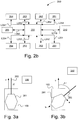
- FIG 3a schematically illustrates a situation for a vehicle 100.
- Said vehicle is hereby exemplified as a combat vehicle with a barrel 262 carried by a pivotable tower 261.
- the vehicle 100 hereby has by means of said sensor configuration 250 detected an object 300 in a surrounding configuration.
- said object is a five meter high tower with rectangular cross section area of two times four meters.
- the vehicle 100 hereby presents a basic configuration wherein said barrel 262 is aiming forwardly in a travel direction of the vehicle. Said barrel 262 and tower 261 hereby present a rotation angle of ⁇ 1 degrees. ⁇ 1 is hereby substantially 0 degrees.
- the vehicles current speed v is indicated hereby.
- no collision risk between said barrel 262 and said object 300 will be present, whereby no indication regarding collision risk needs to be presented for an operator of an vehicle 100.
- an indication comprises information about that no collision risk is presented for said operator.
- an indication comprising information about that it is not suitable to turn to the right in the travel path of the vehicle may be presented.
- FIG 3b schematically illustrates a situation for a vehicle 100.
- Said vehicle is hereby exemplified as a combat vehicle with a barrel 262 carried by a pivotable tower 261.
- the vehicle 100 hereby by means of said sensor configuration 250 has detected an object 300 in a surrounding configuration.
- said object is a 5 meter high tower with rectangular cross-section area of 2 times 4 meters.
- the vehicle 100 hereby presents a total configuration which is not the same as the vehicle basic configuration.
- said tower 261 carrying said barrel 262 is rotated to the right with an angle ⁇ 2 relative a reference direction, where said reference direction is in a longitudinal axis of the vehicle, i.e. forward in a travel direction of the vehicle.
- Said barrel 262 and tower 261 hereby present said rotation angle of ⁇ 2.
- ⁇ 2 is hereby essentially 45 degrees.
- the current speed v of the vehicle is indicated hereby.
- said intended travel path is substantially straight forward immediate collision risk between said barrel 262 and said object 300 is present, whereby indication regarding collision risk needs to be presented to an operator of the vehicle 100.
- an indication comprising information about that the vehicle, because of said provision of collision risk, needs to be braked or driven by turning to the left relative the vehicle current travel direction, is presented for said operator.
- an indication may comprise information about the tower 261 carrying said barrel 262 needs to be rotated in a suitable way to avoid collision with said object 300.
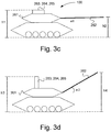
- FIG. 3c schematically illustrates a vehicle 100, which is a tank.
- the vehicle 100 presents a pivotable tower 261 carrying a barrel 262.
- the vehicle also presents a system configuration 260.
- said system configuration may comprise at least one of the third system configuration 263, fourth system configuration 264, or fifth system configuration 265.
- said system configuration 260 is in a folded position.
- Said barrel 262 is hereby in a first position, where a first elevation angle ⁇ 1 is essentially 0 relative a reference direction.
- the vehicle 100 hereby presents a basic configuration, wherein a first height h1 defines a distance between a ground level and an upper side of the system configuration 260.
- a second height h2 further defines a distance between a ground level and portion of the barrel 262 in said second position.
- FIG. 3d schematically illustrates a vehicle 100, which is a tank.
- the vehicle 100 presents a pivotable tower 261 carrying a barrel 262.
- the vehicle presents also a system configuration 260.
- said system configuration may comprise at least one of the third system configuration 263, fourth system configuration 264, or fifth system configuration 265.
- said system configuration 260 is in an unfolded position.
- Said barrel 262 is hereby in a second position, wherein a second elevation angle ⁇ 2 is essentially 30 degrees relative a reference direction.
- the vehicle 100 hereby presents a total configuration which deviates from said basic configuration (such as one for example being presented with reference to figure 3c ), wherein a third height h3 defines a distance between a ground level and an upper side of the system configuration 260 in that unfolded position.
- a fourth height h4 is further defining a distance between a ground level and an end portion of the barrel 262 in said second position.
- both the system configuration 260 and said barrel project from said basic configuration.
- the height measure h3 thus may be used.
- the height measure h4 may thus be used.
- h3 is shorter than h4, why the height H4 defines the total height of the vehicle above ground level.
- various suitable measures may be determined for presentation for an operator of the vehicle 100.
- said measures may pertain to controlling said barrel 262, tower 261 and/or system configuration 260.
- Said measures may be alternatively or as a complement pertain to suitable propulsion of the vehicle 100, comprising changes of vehicle speed.
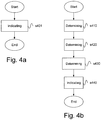
- FIG. 4a schematically illustrates a flowchart for a method for collision risk management pertaining to vehicles comprising portions projecting outside a basic configuration of said vehicle, which portions temporarily may change said basic configuration, according to an embodiment of the invention.
- the method comprises a first method step s401.
- the step s401 comprises the steps of:
- Figure 4b schematically illustrates a flowchart for a method for collision risk management pertaining to vehicles comprising portions projecting outside a basic configuration of said vehicle, which portions temporarily may change said basic configuration, according to an embodiment of the invention.
- the method comprises a first method step S410.
- the method step S410 comprises the step of determining a surrounding configuration as basis for collision risk determination. This may be performed by said sensor configuration 250, comprising at least one of the first sensor configuration 251, second sensor configuration 252, third sensor configuration 253 and fourth sensor configuration 254. Said determined surrounding configuration may be stored in a memory of the first control unit 200. In particular there is determined position and configuration of objects in said determined surrounding configuration. After the method step S410 there is performed a subsequent method step S420.
- the method step S420 comprises the step of determining presence of portions projecting outside said basic configuration. This may be performed by means of said system configuration 260, comprising at least one of said first system configuration 261, second system configuration 262, third system configuration 263, fourth system configuration 264 and fifth system configuration 265. After the method step S420 there is performed a subsequent method step S430.
- the method step S430 comprises the step of determining if collision risk is present at the thus determined surrounding configuration and the thus determined total vehicle configuration. This may be performed by means of routines stored at the first control unit 200. The step of determining if collision risk is present may be performed in a suitable way on the basis of said determined total vehicle configuration and said determined surrounding configuration.
- the step S430 may comprise the step of updating a set of parameters representing said basic configuration. This may be performed by means of said communication unit 270.
- the step S430 may comprise the step of determining said total vehicle configuration on the basis of said basic configuration.
- the step S430 may comprise the step of determining said total vehicle configuration on the basis of said updated basic configuration.
- the step S430 may comprise the step of determining said collision risk on the basis of said updated set of parameters.
- the method step S440 comprises the step of for an operator of a vehicle indicating the thus determined collision risk. This may be performed by means of said presentation means 280.
- the method step S440 may comprise the step of determining suitable measures for managing the thus determined collision risk.
- the method step S440 comprises the step of presenting the thus determined measures for said operator.
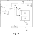
- the control units 200 and 210 described with reference to Figure 2 may in one version comprise the device 500.
- the device 500 comprises a non-volatile memory 520, a data processing unit 510 and a read/write memory 550.
- the non-volatile memory 520 has a first memory element 530 in which a computer programme, e.g. an operating system, is stored for controlling the function of the device 200.
- the device 500 further comprises a bus controller, a serial communication port, I/O means, an A/D converter, a time and date input and transfer unit, an event counter and an interruption controller (not depicted).
- the non-volatile memory 520 has also a second memory element 540.
- a computer programme P which comprises routines for collision risk management pertaining to a vehicle 100 comprising portions projecting outside a basic configuration of said vehicle 100, which portions temporarily may change said basic configuration, according to an aspect of the innovative method.
- the computer programme P comprises routines for determining a surrounding configuration as basis for collision risk determination.
- the computer programme P comprises routines for determining presence of portions projecting outside said basic configuration.
- the computer programme P comprises routines for determining if collision risk is present at the thus determined surrounding configuration and the thus determined total vehicle configuration.
- the computer programme P comprises routines for an operator of the vehicle indicating said thus determined collision risk.
- the computer programme P can comprise routines for determining suitable measures for managing the thus determined collision risk.
- the computer programme P comprises routines for presenting the thus determined measures for said operator.
- the computer programme P comprises routines for determining a current position and/or velocity of the vehicle.
- the computer programme P comprises routines for determining the vehicle configuration paying regard to said projecting portions.
- the computer programme P comprises routines for determining changes of the propulsion of said vehicle and/or change of said determined vehicle configuration.
- the computer programme P comprises routines for determining said measures on the basis of information about changes of the propulsion of said vehicle and/or changes of said determined vehicle configuration by means of said projecting portions.
- the computer programme P comprises routines for indicating the thus determined collision risk by visual presentation via a presentation screen and/or periscope.
- the computer programme P comprises routines for updating a set of parameters representing said basic configuration.
- the computer programme P comprises routines for determining said collision risk on the basis of said updated set of parameters.
- the computer programme P comprises routines for continuously or intermittently determining the intended travel path of the vehicle.
- the computer programme P comprises routines for continuously determining said collision risk on the basis of the intended travel path of the vehicle.
- the computer programme P comprises routines for continuously determining a solid angle of a pivotable and vertically adjustable barrel.
- the computer programme P comprises routines for continuously determining an angle of rotation of a pivotable tower carrying said barrel.
- the computer programme P may be stored in an executable form or in compressed form in a memory 560 and/or in a read/write memory 550.
- the data processing unit 510 performs a certain function, it means that it conducts a certain part of the programme which is stored in the memory 560 or a certain part of the programme which is stored in the read/write memory 550.
- the data processing device 510 can communicate with a data port 599 via a data bus 515.
- the non-volatile memory 520 is intended for communication with the data processing unit 510 via a data bus 512.
- the separate memory 560 is intended to communicate with the data processing unit via a data bus 511.
- the read/write memory 550 is arranged to communicate with the data processing unit 510 via a data bus 514.
- the links L210, L240, L260, L270, L280, L251, L252, L253, L254, L261, L262, L263, L264 and L265, for example, may be connected to the data port 599 (see Figure 2a and Figure 2b ).
- signals received on the data port 599 comprise information about a determined solid angle of a pivotable and vertically adjustable barrel.
- signals received on the data port 599 comprise information about an angle of rotation of a pivotable tower carrying said barrel.
- signals received on the data port 599 comprise information about a detected surrounding configuration.
- signals received on the data port 599 comprise information about the determined total vehicle configuration.
- the signals received on the data port 599 may be used by the device 500 for determining if collision risk is present at the thus determined surrounding configuration and the thus determined total vehicle configuration;
- Parts of the methods herein described may be conducted by the device 500 by means of the data processing unit 510 which runs the programme stored in the memory 560 or the read/write memory 550. When the device 500 runs the programme, methods herein described are executed.
Landscapes
- Engineering & Computer Science (AREA)
- Radar, Positioning & Navigation (AREA)
- Remote Sensing (AREA)
- Physics & Mathematics (AREA)
- General Physics & Mathematics (AREA)
- Computer Networks & Wireless Communication (AREA)
- Electromagnetism (AREA)
- Acoustics & Sound (AREA)
- General Engineering & Computer Science (AREA)
- Multimedia (AREA)
- Theoretical Computer Science (AREA)
- Traffic Control Systems (AREA)
Claims (14)
- Verfahren zur Kollisionsrisikoverwaltung in Bezug auf einen Panzer (100), der außerhalb einer Grundkonfiguration des Panzers vorstehende Teile umfasst, umfassend die folgenden Schritte:- Bestimmen (S410) einer Umgebungskonfiguration als Grundlage für eine Kollisionsrisikobestimmung; und- Bestimmen (S420) des Vorhandenseins von außerhalb der Grundkonfiguration vorstehenden Teilen durch das Bestimmen einer Gesamtfahrzeugkonfiguration unter Berücksichtigung von aus der Grundkonfiguration vorstehenden Teilen von Systemen,gekennzeichnet durch die folgenden Schritte:- Bestimmen (S430), ob ein Kollisionsrisiko an der so bestimmten Umgebungskonfiguration und der so bestimmten Gesamtfahrzeugkonfiguration auf Grundlage kontinuierlich empfangener Signale (S260) von einer Systemkonfiguration (260) des Panzers vorhanden ist, wobei die Signale (S260) Informationen über den aktuellen Zustand und die aktuelle Position von Systemen, die in der Systemkonfiguration (260) enthalten sind, umfassen, wobei die Zustände und Positionen die Ausrichtung eines Turms des Panzers und Informationen über den aktuellen Winkel eines von dem Turm getragenen Laufs umfassen; und- Anzeigen (S440) des so bestimmten Kollisionsrisikos für einen Bediener des Panzers, wobei das so bestimmte Kollisionsrisiko durch visuelle Darstellung über Darstellungsbildschirm und/oder Periskop angezeigt wird.
- Verfahren nach Anspruch 1, wobei der Bediener ein Fahrer des Panzers und/oder ein Bediener für die vorstehenden Teile ist.
- Verfahren nach einem der vorhergehenden Ansprüche, umfassend die folgenden Schritte:- Bestimmen geeigneter Maßnahmen zur Verwaltung des so bestimmten Kollisionsrisikos; und- Darstellen der so bestimmten Maßnahmen für den Bediener.
- Verfahren nach Anspruch 3, wobei die vorgeschlagenen Maßnahmen Änderungen des Antriebs des Panzers und/oder Änderungen der bestimmten Fahrzeugkonfiguration mittels der vorstehenden Teile umfassen.
- Verfahren nach einem der vorhergehenden Ansprüche, umfassend die folgenden Schritte:- Aktualisieren eines Satzes von die Grundkonfiguration darstellenden Parametern;- Bestimmen des Kollisionsrisikos auf der Grundlage des aktualisierten Satzes von Parametern.
- Verfahren nach einem der vorhergehenden Ansprüche, wobei das Kollisionsrisiko kontinuierlich unter Rücksichtnahme auf unter anderem den beabsichtigten Fahrweg des Panzers bestimmt wird.
- Vorrichtung zur Kollisionsrisikoverwaltung in Bezug auf einen Panzer (100), der außerhalb einer Grundkonfiguration des Panzers vorstehende Teile umfasst, umfassend:- Mittel (250; 251; 252;253; 254; 200; 210; 500) zum Bestimmen einer Umgebungskonfiguration als Grundlage für eine Kollisionsrisikobestimmung; und- Mittel (260; 261; 262; 263; 264; 265; 200; 210; 500) zum Bestimmen des Vorhandenseins von außerhalb der Grundkonfiguration vorstehenden Teilen durch das Bestimmen einer Gesamtfahrzeugkonfiguration unter Berücksichtigung von aus der Grundkonfiguration vorstehenden Teilen von Systemen,gekennzeichnet durch:- Mittel (200; 210; 500) zum Bestimmen, ob ein Kollisionsrisiko an der so bestimmten Umgebungskonfiguration und der so bestimmten Gesamtfahrzeugkonfiguration auf Grundlage kontinuierlich empfangener Signale (S260) von einer Systemkonfiguration (260) des Panzers vorhanden ist, wobei die Signale (S260) Informationen über den aktuellen Zustand und die aktuelle Position von Systemen, die in der Systemkonfiguration (260) enthalten sind, umfassen, wobei die Zustände und Positionen die Ausrichtung eines Turms des Panzers und Informationen über den aktuellen Winkel eines von dem Turm getragenen Laufs umfassen; und- Mittel (200; 210; 500; 280) zur Anzeige des so bestimmten Kollisionsrisikos für einen Bediener des Panzers, wobei das so bestimmte Kollisionsrisiko durch visuelle Darstellung über Darstellungsbildschirm und/oder Periskop angezeigt wird.
- Vorrichtung nach Anspruch 7, umfassend:- Mittel (200; 210; 500) zur Bestimmung geeigneter Maßnahmen zur Verwaltung des so bestimmten Kollisionsrisikos; und- Mittel (200; 210; 500; 280) zur Darstellung der so bestimmten Maßnahmen für den Bediener.
- Vorrichtung nach Anspruch 8, wobei die vorgeschlagenen Maßnahmen Änderungen des Antriebs des Panzers und/oder Änderungen der bestimmten Fahrzeugkonfiguration mittels der vorstehenden Teile umfassen.
- Vorrichtung nach einem der Ansprüche 7 bis 9, umfassend:- Mittel (200; 210; 500; 270) zum Aktualisieren eines Satzes von die Grundkonfiguration darstellenden Parametern;- Mittel (200; 210; 500) zum Bestimmen des Kollisionsrisikos auf der Grundlage des aktualisierten Satzes von Parametern.
- Vorrichtung nach einem der Ansprüche 7 bis 10, umfassend:- Mittel (200; 210; 500) zur kontinuierlichen Bestimmung des Kollisionsrisikos unter Rücksichtnahme auf unter anderem den beabsichtigten Fahrweg des Panzers.
- Panzer (100;110), der eine Vorrichtung (299) nach einem der Ansprüche 7 bis 11 umfasst.
- Computerprogramm (P), wobei das Computerprogramm (P) einen Programmcode umfasst, um eine Vorrichtung zur Kollisionsrisikoverwaltung in Bezug auf einen Panzer nach einem der Ansprüche 7 bis 11 dazu zu veranlassen, die Schritte nach einem der Ansprüche 1 bis 6 durchzuführen.
- Computerprogrammprodukt, das einen Programmcode umfasst, der auf einem computerlesbaren Medium zur Durchführung von Verfahrensschritten nach einem der Ansprüche 1 bis 6 gespeichert ist, wenn der Programmcode auf einer Vorrichtung zur Kollisionsrisikoverwaltung in Bezug auf einen Panzer nach einem der Ansprüche 7 bis 11 läuft.
Applications Claiming Priority (2)
| Application Number | Priority Date | Filing Date | Title |
|---|---|---|---|
| SE1350963A SE537332C2 (sv) | 2013-08-21 | 2013-08-21 | Anordning och förfarande för kollisionsriskhantering vid fordon |
| PCT/SE2014/050713 WO2015026279A1 (en) | 2013-08-21 | 2014-06-12 | Device and method for collision risk management for vehicles |
Publications (3)
| Publication Number | Publication Date |
|---|---|
| EP3036731A1 EP3036731A1 (de) | 2016-06-29 |
| EP3036731A4 EP3036731A4 (de) | 2017-03-22 |
| EP3036731B1 true EP3036731B1 (de) | 2020-12-02 |
Family
ID=52483955
Family Applications (1)
| Application Number | Title | Priority Date | Filing Date |
|---|---|---|---|
| EP14837820.1A Active EP3036731B1 (de) | 2013-08-21 | 2014-06-12 | Vorrichtung und verfahren zum kollisionsrisikomanagement für fahrzeuge |
Country Status (6)
| Country | Link |
|---|---|
| US (1) | US10139485B2 (de) |
| EP (1) | EP3036731B1 (de) |
| DK (1) | DK3036731T3 (de) |
| ES (1) | ES2855205T3 (de) |
| SE (1) | SE537332C2 (de) |
| WO (1) | WO2015026279A1 (de) |
Families Citing this family (2)
| Publication number | Priority date | Publication date | Assignee | Title |
|---|---|---|---|---|
| JP6716857B2 (ja) * | 2014-12-26 | 2020-07-01 | 株式会社リコー | 移動体、測定システム、測定方法及びプログラム |
| DE102018200313A1 (de) * | 2018-01-11 | 2019-07-11 | Robert Bosch Gmbh | Verfahren zum Herstellen eines Steuersystems für ein Kraftfahrzeug, Steuersystem |
Family Cites Families (15)
| Publication number | Priority date | Publication date | Assignee | Title |
|---|---|---|---|---|
| US7127331B2 (en) * | 1999-07-30 | 2006-10-24 | Oshkosh Truck Corporation | Turret operator interface system and method for a fire fighting vehicle |
| US7107129B2 (en) * | 2002-02-28 | 2006-09-12 | Oshkosh Truck Corporation | Turret positioning system and method for a fire fighting vehicle |
| US7162332B2 (en) * | 1999-07-30 | 2007-01-09 | Oshkosh Truck Corporation | Turret deployment system and method for a fire fighting vehicle |
| JP2001180374A (ja) | 1999-12-24 | 2001-07-03 | Aisin Aw Co Ltd | 運転支援装置及び運転支援方法 |
| US7277782B2 (en) * | 2001-01-31 | 2007-10-02 | Oshkosh Truck Corporation | Control system and method for electric vehicle |
| JP3796157B2 (ja) | 2001-10-17 | 2006-07-12 | 日本機械工業株式会社 | 高所作業車 |
| US7451028B2 (en) * | 2001-12-21 | 2008-11-11 | Oshkosh Corporation | Turret control system based on stored position for a fire fighting vehicle |
| US8862379B2 (en) * | 2004-09-20 | 2014-10-14 | The Boeing Company | Vehicle collision shield |
| US7734399B2 (en) * | 2006-02-10 | 2010-06-08 | American Lafrance, Llc | Outrigger obstruction detection system for aerial fire trucks |
| KR100713554B1 (ko) | 2006-08-08 | 2007-05-02 | 주식회사 로템 | 전차선회 경보시스템 및 그 방법 |
| US7877209B2 (en) * | 2006-09-26 | 2011-01-25 | Harris Steven M | Radar collison warning system for rooftop mounted cargo |
| DE102007053989A1 (de) * | 2007-11-13 | 2009-05-14 | Wabco Gmbh | Verfahren und Anordnung zur Warnung vor Hindernissen mit nicht ausreichender Durchfahrtshöhe und/oder nicht ausreichender Durchfahrtsbreite |
| US8428827B2 (en) * | 2011-01-21 | 2013-04-23 | Control Solutions LLC | Apparatus and method for controlling rotational movement of a vehicle turret |
| US9032859B2 (en) * | 2011-11-30 | 2015-05-19 | Drs Sustainment Systems, Inc. | Harmonized turret with multiple gimbaled sub-systems |
| US20150145711A1 (en) * | 2013-11-26 | 2015-05-28 | The Regents Of The University Of Michigan | Retro-reflective radar patch antenna target for vehicle and road infrastructure identification |
-
2013
- 2013-08-21 SE SE1350963A patent/SE537332C2/sv unknown
-
2014
- 2014-06-12 ES ES14837820T patent/ES2855205T3/es active Active
- 2014-06-12 EP EP14837820.1A patent/EP3036731B1/de active Active
- 2014-06-12 DK DK14837820.1T patent/DK3036731T3/da active
- 2014-06-12 US US14/913,268 patent/US10139485B2/en active Active
- 2014-06-12 WO PCT/SE2014/050713 patent/WO2015026279A1/en not_active Ceased
Non-Patent Citations (1)
| Title |
|---|
| None * |
Also Published As
| Publication number | Publication date |
|---|---|
| US20160209507A1 (en) | 2016-07-21 |
| WO2015026279A1 (en) | 2015-02-26 |
| EP3036731A4 (de) | 2017-03-22 |
| ES2855205T3 (es) | 2021-09-23 |
| SE537332C2 (sv) | 2015-04-07 |
| US10139485B2 (en) | 2018-11-27 |
| DK3036731T3 (da) | 2021-01-18 |
| SE1350963A1 (sv) | 2015-02-22 |
| EP3036731A1 (de) | 2016-06-29 |
Similar Documents
| Publication | Publication Date | Title |
|---|---|---|
| US20230365128A1 (en) | Multi-Model Switching on a Collision Mitigation System | |
| US10474144B2 (en) | Remote information collection, situational awareness, and adaptive response system for improving advance threat awareness and hazardous risk avoidance | |
| US10040390B2 (en) | Vehicle light diagnostic | |
| US20160019782A1 (en) | Device and method for increasing road safety in vehicle platoons | |
| US20220068141A1 (en) | Platooning control apparatus and method | |
| US9518829B2 (en) | Driving assistance system, vehicle and method | |
| US10940861B2 (en) | Method and system for automatically controlling a following vehicle with a front vehicle | |
| US20220308577A1 (en) | Virtual towing device, system, and method | |
| US20190315348A1 (en) | Vehicle control device, vehicle control method, and storage medium | |
| JP6441902B2 (ja) | タキシングする航空機の近傍可視化システムおよび方法 | |
| US20200166950A1 (en) | Automatic driving control device | |
| CN113401116A (zh) | 用于自主驾驶车辆的方法和系统 | |
| US20180186283A1 (en) | Systems and methods for automatically deploying road hazard indicators | |
| US20160026187A1 (en) | Device and method for choosing leader vehicle of a vehicle platoon | |
| US20170168504A1 (en) | Method and system for automatically controlling a following vehicle with a scout vehicle | |
| EP3597503B1 (de) | Überprüfung der aufmerksamkeit eines fahrzeugführers vor dem übergang vom autonomen in den manuellen modus | |
| US20100023185A1 (en) | Devices and methods for waypoint target generation and mission spooling for mobile ground robots | |
| CN108706009A (zh) | 车辆的行驶控制系统 | |
| CN105082910A (zh) | 辅助将运载工具联接至拖车的系统和方法 | |
| CN108698600A (zh) | 带有自动行驶能力的车辆 | |
| US20180253607A1 (en) | System for receiving and analyzing traffic video | |
| CN110884503A (zh) | 用于测试机动车的自动化驾驶功能的方法、设备及存储介质 | |
| US10139485B2 (en) | Device and method for collision risk management for vehicles | |
| CN107357306A (zh) | 一种引导方法、设备、计算机设备和可读存储介质 | |
| KR20180054186A (ko) | 비행장 내에서 드론을 이용하여 조류 퇴치 시스템 및 방법 |
Legal Events
| Date | Code | Title | Description |
|---|---|---|---|
| PUAI | Public reference made under article 153(3) epc to a published international application that has entered the european phase |
Free format text: ORIGINAL CODE: 0009012 |
|
| 17P | Request for examination filed |
Effective date: 20160222 |
|
| AK | Designated contracting states |
Kind code of ref document: A1 Designated state(s): AL AT BE BG CH CY CZ DE DK EE ES FI FR GB GR HR HU IE IS IT LI LT LU LV MC MK MT NL NO PL PT RO RS SE SI SK SM TR |
|
| AX | Request for extension of the european patent |
Extension state: BA ME |
|
| DAX | Request for extension of the european patent (deleted) | ||
| A4 | Supplementary search report drawn up and despatched |
Effective date: 20170217 |
|
| RIC1 | Information provided on ipc code assigned before grant |
Ipc: G08G 1/16 20060101AFI20170213BHEP Ipc: G01S 13/93 20060101ALI20170213BHEP Ipc: G01S 17/93 20060101ALI20170213BHEP Ipc: G01S 17/02 20060101ALI20170213BHEP Ipc: F41A 27/00 20060101ALI20170213BHEP Ipc: F41H 7/02 20060101ALI20170213BHEP Ipc: G01S 15/02 20060101ALI20170213BHEP Ipc: G06K 9/00 20060101ALI20170213BHEP Ipc: G01S 13/86 20060101ALI20170213BHEP Ipc: G01S 15/93 20060101ALI20170213BHEP |
|
| STAA | Information on the status of an ep patent application or granted ep patent |
Free format text: STATUS: EXAMINATION IS IN PROGRESS |
|
| 17Q | First examination report despatched |
Effective date: 20181217 |
|
| GRAP | Despatch of communication of intention to grant a patent |
Free format text: ORIGINAL CODE: EPIDOSNIGR1 |
|
| STAA | Information on the status of an ep patent application or granted ep patent |
Free format text: STATUS: GRANT OF PATENT IS INTENDED |
|
| INTG | Intention to grant announced |
Effective date: 20200728 |
|
| GRAS | Grant fee paid |
Free format text: ORIGINAL CODE: EPIDOSNIGR3 |
|
| GRAA | (expected) grant |
Free format text: ORIGINAL CODE: 0009210 |
|
| STAA | Information on the status of an ep patent application or granted ep patent |
Free format text: STATUS: THE PATENT HAS BEEN GRANTED |
|
| AK | Designated contracting states |
Kind code of ref document: B1 Designated state(s): AL AT BE BG CH CY CZ DE DK EE ES FI FR GB GR HR HU IE IS IT LI LT LU LV MC MK MT NL NO PL PT RO RS SE SI SK SM TR |
|
| REG | Reference to a national code |
Ref country code: GB Ref legal event code: FG4D |
|
| REG | Reference to a national code |
Ref country code: AT Ref legal event code: REF Ref document number: 1341784 Country of ref document: AT Kind code of ref document: T Effective date: 20201215 Ref country code: CH Ref legal event code: EP |
|
| REG | Reference to a national code |
Ref country code: DE Ref legal event code: R096 Ref document number: 602014073011 Country of ref document: DE |
|
| REG | Reference to a national code |
Ref country code: IE Ref legal event code: FG4D |
|
| REG | Reference to a national code |
Ref country code: DK Ref legal event code: T3 Effective date: 20210111 |
|
| REG | Reference to a national code |
Ref country code: FI Ref legal event code: FGE |
|
| REG | Reference to a national code |
Ref country code: NL Ref legal event code: FP |
|
| REG | Reference to a national code |
Ref country code: EE Ref legal event code: FG4A Ref document number: E020228 Country of ref document: EE Effective date: 20201222 |
|
| REG | Reference to a national code |
Ref country code: NO Ref legal event code: T2 Effective date: 20201202 |
|
| PG25 | Lapsed in a contracting state [announced via postgrant information from national office to epo] |
Ref country code: RS Free format text: LAPSE BECAUSE OF FAILURE TO SUBMIT A TRANSLATION OF THE DESCRIPTION OR TO PAY THE FEE WITHIN THE PRESCRIBED TIME-LIMIT Effective date: 20201202 Ref country code: GR Free format text: LAPSE BECAUSE OF FAILURE TO SUBMIT A TRANSLATION OF THE DESCRIPTION OR TO PAY THE FEE WITHIN THE PRESCRIBED TIME-LIMIT Effective date: 20210303 |
|
| PG25 | Lapsed in a contracting state [announced via postgrant information from national office to epo] |
Ref country code: LV Free format text: LAPSE BECAUSE OF FAILURE TO SUBMIT A TRANSLATION OF THE DESCRIPTION OR TO PAY THE FEE WITHIN THE PRESCRIBED TIME-LIMIT Effective date: 20201202 Ref country code: PL Free format text: LAPSE BECAUSE OF FAILURE TO SUBMIT A TRANSLATION OF THE DESCRIPTION OR TO PAY THE FEE WITHIN THE PRESCRIBED TIME-LIMIT Effective date: 20201202 Ref country code: SE Free format text: LAPSE BECAUSE OF FAILURE TO SUBMIT A TRANSLATION OF THE DESCRIPTION OR TO PAY THE FEE WITHIN THE PRESCRIBED TIME-LIMIT Effective date: 20201202 Ref country code: BG Free format text: LAPSE BECAUSE OF FAILURE TO SUBMIT A TRANSLATION OF THE DESCRIPTION OR TO PAY THE FEE WITHIN THE PRESCRIBED TIME-LIMIT Effective date: 20210302 |
|
| PG25 | Lapsed in a contracting state [announced via postgrant information from national office to epo] |
Ref country code: HR Free format text: LAPSE BECAUSE OF FAILURE TO SUBMIT A TRANSLATION OF THE DESCRIPTION OR TO PAY THE FEE WITHIN THE PRESCRIBED TIME-LIMIT Effective date: 20201202 |
|
| REG | Reference to a national code |
Ref country code: LT Ref legal event code: MG9D |
|
| PG25 | Lapsed in a contracting state [announced via postgrant information from national office to epo] |
Ref country code: SM Free format text: LAPSE BECAUSE OF FAILURE TO SUBMIT A TRANSLATION OF THE DESCRIPTION OR TO PAY THE FEE WITHIN THE PRESCRIBED TIME-LIMIT Effective date: 20201202 Ref country code: PT Free format text: LAPSE BECAUSE OF FAILURE TO SUBMIT A TRANSLATION OF THE DESCRIPTION OR TO PAY THE FEE WITHIN THE PRESCRIBED TIME-LIMIT Effective date: 20210405 Ref country code: SK Free format text: LAPSE BECAUSE OF FAILURE TO SUBMIT A TRANSLATION OF THE DESCRIPTION OR TO PAY THE FEE WITHIN THE PRESCRIBED TIME-LIMIT Effective date: 20201202 Ref country code: RO Free format text: LAPSE BECAUSE OF FAILURE TO SUBMIT A TRANSLATION OF THE DESCRIPTION OR TO PAY THE FEE WITHIN THE PRESCRIBED TIME-LIMIT Effective date: 20201202 Ref country code: LT Free format text: LAPSE BECAUSE OF FAILURE TO SUBMIT A TRANSLATION OF THE DESCRIPTION OR TO PAY THE FEE WITHIN THE PRESCRIBED TIME-LIMIT Effective date: 20201202 |
|
| REG | Reference to a national code |
Ref country code: AT Ref legal event code: UEP Ref document number: 1341784 Country of ref document: AT Kind code of ref document: T Effective date: 20201202 |
|
| REG | Reference to a national code |
Ref country code: DE Ref legal event code: R097 Ref document number: 602014073011 Country of ref document: DE |
|
| REG | Reference to a national code |
Ref country code: ES Ref legal event code: FG2A Ref document number: 2855205 Country of ref document: ES Kind code of ref document: T3 Effective date: 20210923 |
|
| PG25 | Lapsed in a contracting state [announced via postgrant information from national office to epo] |
Ref country code: IS Free format text: LAPSE BECAUSE OF FAILURE TO SUBMIT A TRANSLATION OF THE DESCRIPTION OR TO PAY THE FEE WITHIN THE PRESCRIBED TIME-LIMIT Effective date: 20210402 |
|
| PLBE | No opposition filed within time limit |
Free format text: ORIGINAL CODE: 0009261 |
|
| STAA | Information on the status of an ep patent application or granted ep patent |
Free format text: STATUS: NO OPPOSITION FILED WITHIN TIME LIMIT |
|
| PG25 | Lapsed in a contracting state [announced via postgrant information from national office to epo] |
Ref country code: IT Free format text: LAPSE BECAUSE OF FAILURE TO SUBMIT A TRANSLATION OF THE DESCRIPTION OR TO PAY THE FEE WITHIN THE PRESCRIBED TIME-LIMIT Effective date: 20201202 Ref country code: AL Free format text: LAPSE BECAUSE OF FAILURE TO SUBMIT A TRANSLATION OF THE DESCRIPTION OR TO PAY THE FEE WITHIN THE PRESCRIBED TIME-LIMIT Effective date: 20201202 |
|
| 26N | No opposition filed |
Effective date: 20210903 |
|
| PG25 | Lapsed in a contracting state [announced via postgrant information from national office to epo] |
Ref country code: SI Free format text: LAPSE BECAUSE OF FAILURE TO SUBMIT A TRANSLATION OF THE DESCRIPTION OR TO PAY THE FEE WITHIN THE PRESCRIBED TIME-LIMIT Effective date: 20201202 |
|
| PG25 | Lapsed in a contracting state [announced via postgrant information from national office to epo] |
Ref country code: MC Free format text: LAPSE BECAUSE OF FAILURE TO SUBMIT A TRANSLATION OF THE DESCRIPTION OR TO PAY THE FEE WITHIN THE PRESCRIBED TIME-LIMIT Effective date: 20201202 |
|
| REG | Reference to a national code |
Ref country code: BE Ref legal event code: MM Effective date: 20210630 |
|
| PG25 | Lapsed in a contracting state [announced via postgrant information from national office to epo] |
Ref country code: LU Free format text: LAPSE BECAUSE OF NON-PAYMENT OF DUE FEES Effective date: 20210612 |
|
| PG25 | Lapsed in a contracting state [announced via postgrant information from national office to epo] |
Ref country code: IE Free format text: LAPSE BECAUSE OF NON-PAYMENT OF DUE FEES Effective date: 20210612 |
|
| PG25 | Lapsed in a contracting state [announced via postgrant information from national office to epo] |
Ref country code: IS Free format text: LAPSE BECAUSE OF FAILURE TO SUBMIT A TRANSLATION OF THE DESCRIPTION OR TO PAY THE FEE WITHIN THE PRESCRIBED TIME-LIMIT Effective date: 20210402 Ref country code: FR Free format text: LAPSE BECAUSE OF NON-PAYMENT OF DUE FEES Effective date: 20210630 |
|
| PG25 | Lapsed in a contracting state [announced via postgrant information from national office to epo] |
Ref country code: BE Free format text: LAPSE BECAUSE OF NON-PAYMENT OF DUE FEES Effective date: 20210630 |
|
| PG25 | Lapsed in a contracting state [announced via postgrant information from national office to epo] |
Ref country code: HU Free format text: LAPSE BECAUSE OF FAILURE TO SUBMIT A TRANSLATION OF THE DESCRIPTION OR TO PAY THE FEE WITHIN THE PRESCRIBED TIME-LIMIT; INVALID AB INITIO Effective date: 20140612 |
|
| PG25 | Lapsed in a contracting state [announced via postgrant information from national office to epo] |
Ref country code: CY Free format text: LAPSE BECAUSE OF FAILURE TO SUBMIT A TRANSLATION OF THE DESCRIPTION OR TO PAY THE FEE WITHIN THE PRESCRIBED TIME-LIMIT Effective date: 20201202 |
|
| P01 | Opt-out of the competence of the unified patent court (upc) registered |
Effective date: 20230525 |
|
| PG25 | Lapsed in a contracting state [announced via postgrant information from national office to epo] |
Ref country code: MK Free format text: LAPSE BECAUSE OF FAILURE TO SUBMIT A TRANSLATION OF THE DESCRIPTION OR TO PAY THE FEE WITHIN THE PRESCRIBED TIME-LIMIT Effective date: 20201202 |
|
| PG25 | Lapsed in a contracting state [announced via postgrant information from national office to epo] |
Ref country code: TR Free format text: LAPSE BECAUSE OF FAILURE TO SUBMIT A TRANSLATION OF THE DESCRIPTION OR TO PAY THE FEE WITHIN THE PRESCRIBED TIME-LIMIT Effective date: 20201202 |
|
| PG25 | Lapsed in a contracting state [announced via postgrant information from national office to epo] |
Ref country code: MT Free format text: LAPSE BECAUSE OF FAILURE TO SUBMIT A TRANSLATION OF THE DESCRIPTION OR TO PAY THE FEE WITHIN THE PRESCRIBED TIME-LIMIT Effective date: 20201202 |
|
| PGFP | Annual fee paid to national office [announced via postgrant information from national office to epo] |
Ref country code: NL Payment date: 20250417 Year of fee payment: 12 |
|
| PGFP | Annual fee paid to national office [announced via postgrant information from national office to epo] |
Ref country code: FI Payment date: 20250521 Year of fee payment: 12 |
|
| PGFP | Annual fee paid to national office [announced via postgrant information from national office to epo] |
Ref country code: DE Payment date: 20250521 Year of fee payment: 12 |
|
| PGFP | Annual fee paid to national office [announced via postgrant information from national office to epo] |
Ref country code: GB Payment date: 20250417 Year of fee payment: 12 Ref country code: DK Payment date: 20250416 Year of fee payment: 12 |
|
| PGFP | Annual fee paid to national office [announced via postgrant information from national office to epo] |
Ref country code: NO Payment date: 20250523 Year of fee payment: 12 |
|
| PGFP | Annual fee paid to national office [announced via postgrant information from national office to epo] |
Ref country code: EE Payment date: 20250506 Year of fee payment: 12 |
|
| PGFP | Annual fee paid to national office [announced via postgrant information from national office to epo] |
Ref country code: AT Payment date: 20250519 Year of fee payment: 12 |
|
| PGFP | Annual fee paid to national office [announced via postgrant information from national office to epo] |
Ref country code: CZ Payment date: 20250410 Year of fee payment: 12 |
|
| PGFP | Annual fee paid to national office [announced via postgrant information from national office to epo] |
Ref country code: ES Payment date: 20250829 Year of fee payment: 12 |
|
| PGFP | Annual fee paid to national office [announced via postgrant information from national office to epo] |
Ref country code: CH Payment date: 20250701 Year of fee payment: 12 |