EP3036151B1 - Véhicule comportant un entraînement d'assistance électrique et une transmission à trains épicycloïdaux à variation continue - Google Patents
Véhicule comportant un entraînement d'assistance électrique et une transmission à trains épicycloïdaux à variation continue Download PDFInfo
- Publication number
- EP3036151B1 EP3036151B1 EP14736405.3A EP14736405A EP3036151B1 EP 3036151 B1 EP3036151 B1 EP 3036151B1 EP 14736405 A EP14736405 A EP 14736405A EP 3036151 B1 EP3036151 B1 EP 3036151B1
- Authority
- EP
- European Patent Office
- Prior art keywords
- planetary gear
- continuously variable
- gear mechanism
- gear
- drive
- Prior art date
- Legal status (The legal status is an assumption and is not a legal conclusion. Google has not performed a legal analysis and makes no representation as to the accuracy of the status listed.)
- Active
Links
Images





Classifications
-
- B—PERFORMING OPERATIONS; TRANSPORTING
- B62—LAND VEHICLES FOR TRAVELLING OTHERWISE THAN ON RAILS
- B62M—RIDER PROPULSION OF WHEELED VEHICLES OR SLEDGES; POWERED PROPULSION OF SLEDGES OR SINGLE-TRACK CYCLES; TRANSMISSIONS SPECIALLY ADAPTED FOR SUCH VEHICLES
- B62M6/00—Rider propulsion of wheeled vehicles with additional source of power, e.g. combustion engine or electric motor
- B62M6/40—Rider propelled cycles with auxiliary electric motor
- B62M6/55—Rider propelled cycles with auxiliary electric motor power-driven at crank shafts parts
-
- B—PERFORMING OPERATIONS; TRANSPORTING
- B62—LAND VEHICLES FOR TRAVELLING OTHERWISE THAN ON RAILS
- B62M—RIDER PROPULSION OF WHEELED VEHICLES OR SLEDGES; POWERED PROPULSION OF SLEDGES OR SINGLE-TRACK CYCLES; TRANSMISSIONS SPECIALLY ADAPTED FOR SUCH VEHICLES
- B62M11/00—Transmissions characterised by the use of interengaging toothed wheels or frictionally-engaging wheels
- B62M11/04—Transmissions characterised by the use of interengaging toothed wheels or frictionally-engaging wheels of changeable ratio
- B62M11/14—Transmissions characterised by the use of interengaging toothed wheels or frictionally-engaging wheels of changeable ratio with planetary gears
-
- B—PERFORMING OPERATIONS; TRANSPORTING
- B62—LAND VEHICLES FOR TRAVELLING OTHERWISE THAN ON RAILS
- B62M—RIDER PROPULSION OF WHEELED VEHICLES OR SLEDGES; POWERED PROPULSION OF SLEDGES OR SINGLE-TRACK CYCLES; TRANSMISSIONS SPECIALLY ADAPTED FOR SUCH VEHICLES
- B62M11/00—Transmissions characterised by the use of interengaging toothed wheels or frictionally-engaging wheels
- B62M11/04—Transmissions characterised by the use of interengaging toothed wheels or frictionally-engaging wheels of changeable ratio
- B62M11/14—Transmissions characterised by the use of interengaging toothed wheels or frictionally-engaging wheels of changeable ratio with planetary gears
- B62M11/145—Transmissions characterised by the use of interengaging toothed wheels or frictionally-engaging wheels of changeable ratio with planetary gears built in, or adjacent to, the bottom bracket
-
- B—PERFORMING OPERATIONS; TRANSPORTING
- B62—LAND VEHICLES FOR TRAVELLING OTHERWISE THAN ON RAILS
- B62M—RIDER PROPULSION OF WHEELED VEHICLES OR SLEDGES; POWERED PROPULSION OF SLEDGES OR SINGLE-TRACK CYCLES; TRANSMISSIONS SPECIALLY ADAPTED FOR SUCH VEHICLES
- B62M11/00—Transmissions characterised by the use of interengaging toothed wheels or frictionally-engaging wheels
- B62M11/04—Transmissions characterised by the use of interengaging toothed wheels or frictionally-engaging wheels of changeable ratio
- B62M11/14—Transmissions characterised by the use of interengaging toothed wheels or frictionally-engaging wheels of changeable ratio with planetary gears
- B62M11/18—Transmissions characterised by the use of interengaging toothed wheels or frictionally-engaging wheels of changeable ratio with planetary gears with a plurality of planetary gear units
Definitions
- the present invention relates to a vehicle with an electrical auxiliary drive, which can be driven with motor power and / or pedal force, in particular an electric bicycle, with a continuously variable planetary gear.
- Vehicles which can be driven with motor power and / or pedal power are known, for example, as electric bicycles, for example as pedelecs.
- electric bicycles in which the electric drive is arranged in the area of the bottom bracket (mid-engine concept).
- a rear wheel is then driven via a chain.
- a switching device such as a derailleur or a hub gear or the like, can be arranged on the rear wheel.
- a stepless hub gear on the rear wheel is also known, as exemplified in the US 2012/0309579 A1 is described.
- a vehicle according to the preamble of claim 1 known from the DE 102012109637 A1 a vehicle according to the preamble of claim 1 known.
- the most common switching devices arranged on the rear wheel each have jumps between the individual switching stages.
- a switching device located on the bicycle in particular an electric bicycle, can be controlled automatically. Both systems, the switching device located on the rear wheel and the electric drive with motor support and driver request sensing, work in tandem and are not optimally coordinated with one another, particularly in the case of automatically controlled switching devices and in the event of jumps between the switching stages.
- the high weight, in particular of the hub gears on the rear wheel does not represent an optimal weight distribution for handling, suspension and driving dynamics. In addition, disassembly and assembly of the rear wheel with the switching device is often very complex and cost-intensive.
- the font DE 10 2012 109 637 A1 discloses a bicycle drive unit having a motor with a hole in which a crank axis can be arranged.
- the bicycle drive unit further includes a transmission mechanism with a plurality of selectable gear ratios and an output part, which is designed to add an output of the transmission mechanism and an output of the engine.
- the document DE 10 2009 046 867 A1 discloses a bicycle comprising a crank mechanism, an electric motor and a drive shaft, the drive shaft being connected to a rear wheel via a bevel gear.
- WO 2010/001362 A1 discloses a bicycle in which a continuously variable transmission is arranged in a hub of the rear wheel.
- the vehicle according to the invention which can be driven with motor power and / or pedal force, in particular an electric bicycle, with the features of claim 1 has the advantage over the fact that the integration of a continuously adjustable common housing, is possible. In this way, in particular, an optimal coordination between the electric drive and the switching device can be achieved. Furthermore, according to the invention, a separate switching device on the rear wheel of the vehicle can be dispensed with.
- the idea according to the invention combines the electric drive with a reduction gear for reducing the speed of the engine and a planetary gear with a continuously variable transmission in the area of the crank drive of the vehicle. A particularly compact and lightweight construction is thus achieved. In particular, different components can be used together by the electric drive and the switching device, so that a number of parts can be reduced.
- a continuously variable planetary gear is understood to be a gear in which there is an input disk, an output disk and rotating and inclinable balls.
- an axially movable, central actuator which can pivot an axis of the balls around a ball center. This changes the diameters relevant for the translation between the balls and the input disc or output disc.
- a transition between the relevant diameters of the balls takes place continuously over the ball surface.
- the ball axis is preferably adjusted by means of an actuator.
- the present invention now enables the integration of such a continuously variable planetary gear with an electric drive and with a reduction gear in the area of a crank mechanism of the vehicle. This results in a particularly compact design, in particular a separate switching device on the rear wheel of the vehicle can be dispensed with.
- an input element of the continuously variable planetary gear is also connected to the crank mechanism and the electric drive, a pedal drive torque applied by a driver and an electric drive torque applied by the electric drive being introduced via the same input element of the continuously variable planetary gear, so that the summation of the two torques in front of the continuously variable planetary gear.
- a pedal drive torque applied by a driver and an electric drive torque applied by the electric drive are applied via the same input element of the continuously variable planetary gear brought in. This results in the summation of the two torques in front of the continuously variable planetary gear, since a reduction gear for reducing the speed of the motor advantageously has a fixed gear ratio that is matched to the driver's pedaling frequency. Another advantage is that a stepless transmission ratio change is possible both when the pedal drive torque is present or when the electrical drive torque is exclusively present.
- the continuously variable planetary gear can be arranged concentrically around the crankshaft or with its central axis parallel to the crank axis.
- a concentric arrangement means a particularly compact structure.
- An arrangement running parallel to the crankshaft has the particular advantage of a modular construction of the crank drive, in which, according to a modular system, a conventional crank drive without an integrated circuit can be inexpensively and easily expanded to a system with an integrated continuously variable planetary gear.
- the steplessly adjustable planetary gear further preferably has an input element on which a gear, in particular a spur gear or a second planetary gear or a worm gear, is connected upstream.
- the second planetary gear can be a continuously adjustable planetary gear as well as a conventional planetary gear, switchable in stages or with a fixed ratio, with sun gear, planet, planet gear carrier and ring gear, which are designed as gear wheels.
- the upstream transmission is also connected to the reduction gear of the electric drive and / or the crank drive. Gears are preferably used together.
- the continuously variable planetary gear preferably also has an output element on which a further gear, in particular a spur gear or a planetary gear, is connected.
- the downstream planetary gear can also be a continuously adjustable planetary gear as well as a conventional planetary gear, switchable in stages or with a fixed ratio, with sun gear, planet, planet gear carrier and ring gear, which are designed as gear wheels.
- the electric drive and the like are preferred Infinitely adjustable planetary gear set on a common side of the bottom bracket shaft, especially above the bottom bracket shaft.
- both the continuously variable planetary gear and an upstream and / or downstream further gear are concentric around the bottom bracket shaft arranged.
- the electric drive is further preferably arranged within the continuously variable planetary gear.
- the electric drive is arranged outside the continuously variable planetary gear, in particular above the continuously variable planetary gear. This also allows a higher ground clearance in the area of the crank mechanism to be achieved.
- a bottom bracket shaft of the crank drive and a central axis of the output element e.g. a central axis of the chainring, apart.
- the electric drive is connected in a coaxial arrangement to the central axis of the chainring and to the central axis of the continuously variable planetary gear with a second gear planetary gear, an output of the second planetary gear being connected to the sun gear of the continuously variable planetary gear.
- the sun gear of the continuously variable planetary gear is preferably designed as a ring gear for the second internal planetary gear.
- the output element for example the chainring, is preferably arranged on a hollow shaft.
- the crank mechanism is coupled to an input element of the continuously variable planetary gear via a freewheel.
- the output element e.g. the chainring is freely rotatable around the crankshaft.
- the crank mechanism is always connected to the output element via the continuously variable planetary gear.
- Another preferred embodiment of the invention is the arrangement of the output element, e.g. of the chainring, on the side of the input element of the continuously variable planetary gear.
- the input and output are now on the same side of the continuously variable planetary gear, and this favors flanging onto existing structures.
- the connection of the output element of the continuously variable planetary gear to the output element, e.g. the chainring also take place via a belt drive not according to the invention.
- the steplessly adjustable planetary gear is preferably adjusted by means of an actuator.
- the continuously variable planetary gear can take over the function of an automatic or automatable bicycle shift.
- the reduction gear of the electric drive is further preferably a spur gear or a gear-based planetary gear or a worm gear.
- an additional gear is preferably arranged between the reduction gear of the drive and the continuously variable planetary gear.
- the reduction gear and the additional upstream gear particularly preferably have common parts, for example a common gear.
- a further downstream gear is provided in front of the output element (chainring) on the output element of the continuously variable planetary gear.
- the upstream and / or downstream transmission is preferably designed as a belt drive.
- the idea according to the invention is particularly preferably used in connection with an electric bicycle with a mid-motor drive.
- the electric drive is arranged in the area of the crank drive, and it is possible that, for example, a bicycle manufacturer can be provided with a complete structural unit, including the electric drive and the continuously variable transmission as an automatic switching device. In such a unit, the electric drive and the continuously variable transmission can be optimally coordinated.
- the electric bicycle 1 comprises a crank mechanism 2 with two cranks 7, 8 and two pedals 21, 22.
- the reference numeral 20 designates a crankshaft (cf. Figure 2 ).
- An electric drive 3 is integrated in the crank mechanism 2.
- a pinion 6 is arranged on a rear wheel 9.
- a drive torque is transmitted from a chainring 4 to the pinion 6 via a chain 5.
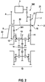
- the drive unit is in detail Figure 2 shown. Both a drive torque provided by the electric drive 3 and a pedal torque can be supplied to the chainring 4.
- a continuously variable planetary gear 10 is arranged between the chainring 4 and the crankshaft 20.
- the connection between the crankshaft 20 and the continuously variable planetary gear 10 takes place via a first freewheel 15 which, when pedaling forward, ensures that the continuously variable planetary gear is carried along and that no torque is transmitted to the chainring 4 when pedaling backwards.
- An input element 11 of the continuously variable planetary gear 10 is preceded by a spur gear 17 which establishes the connection to the crankshaft 20 and a reduction gear 300 of the electric drive 3.
- the spur gear attached to the crankshaft 20 of the transmission upstream of the input element 11 is also part of the reduction gear of the electric drive 3.
- a further spur gear 301 is connected downstream of the output element 12 of the continuously variable planetary gear 10 and establishes the connection to the chainring 4.
- the continuously variable planetary gear is a continuously adjustable actuating device with the input element 11, the output element 12, a plurality of rotating and inclinable balls 13 and a central actuator 14, which also serves as a rolling surface for the balls.
- a translation between the Drive side and the output side (chainring) can be reached. Stepless gear shifting is thus possible for the electric bicycle 1, so that a gear shift on the rear wheel of the bicycle can be dispensed with.
- a traction fluid is arranged between the input element 11 and the output element 12 and in particular in the contact area between the balls 13 and the input element 11 and output element 12 in order to enable the torque transmission.
- the electric drive 3 and the continuously variable planetary gear 10 can be connected at almost any angle, e.g. 180 °, on the crankshaft 20 opposite to each other.
- the angular range is limited by the dimensions of the individual components and the maximum ground clearance that can be achieved.
- the connection via two spur gear stages favors a modular structure in which the continuously variable planetary gear 10 can be added to a conventional structure without an integrated circuit in a simple manner using a modular system.
- an infinitely variable gear shift and the electric drive 3 with reduction gear on the crank mechanism 2 are thus integrated.
- a common housing for crank drive 2, electric drive 3 with reduction gear and continuously adjustable planetary gear 10 is preferably provided.
- a preassembled, compact unit can be provided, which can be easily attached to existing bicycle frames.
- each ball 13 is indicated as three variable diameter gear wheels for the two outer gear wheels, each indicated by the arrow indicating the adjustability.
- the balls are held in a cage, which essentially corresponds to the planet carrier of a conventional planetary gear.
- the central actuator 14 can be adjusted in the axial direction by means of an actuator, not shown, and corresponds to the sun gear of a conventional planetary gear.
- FIG 3 shows a crank mechanism 2 for an electric bicycle according to a second embodiment of the invention.
- the crank mechanism 2 of the second exemplary embodiment essentially corresponds to that of the first exemplary embodiment, a conventional (gear-based) planetary gear 30 with a sun gear 31, planet 32 and a ring gear 33 being additionally provided.
- the electric drive 3 is connected to the ring gear 33 of the planetary gear 30 via a first spur gear toothing 16 with gear wheels 51, 52 connected.
- the input element 11 is connected to a planet gear carrier 34 of the planetary gear 30.
- the sun gear 31 is arranged on the crankshaft 20 via a freewheel.
- a drive torque generated by pedaling can be introduced into the conventional planetary gear 30 via the sun gear 31 and transmitted from there to the chainring 4 via the continuously variable planetary gear 10.
- a drive torque applied by the electric drive 3 is introduced into the planetary gear 30 via the ring gear 33 and is transmitted from there to the chainring 4 via the continuously adjustable planetary gear 10.
- the continuously variable planetary gear 10 is arranged concentrically around the crankshaft 20.
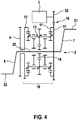
- FIG 4 shows a drive unit of an electric bicycle according to a third embodiment of the invention.
- the continuously variable planetary gear 10 is again arranged concentrically around the crankshaft 20.
- the electric drive 3 is arranged outside the continuously variable planetary gear 10.
- the electric drive 3 can be arranged above the continuously adjustable planetary gear 10, so that there is as high a ground clearance as possible in the area of the crank drive 2.
- the central actuator 14 (sun gear) of the continuously variable planetary gear is freely supported.
- a first spur gear toothing 16 with gears 51, 52 is also provided, the electric drive 3 being connected to the gear 52 and the crankshaft 2 being connected to the gear 51.
- the gear 51 is in turn connected to the input element 11 of the continuously variable planetary gear.
- Figure 5 shows a fourth embodiment of the invention, in which the electric drive 3 is arranged within the continuously variable planetary gear 10.
- the electric drive 3 is connected via a spur gear toothing 16 with gears 53, 54 to the crankshaft 20.
- the crankshaft 20 is connected via the input element 11 to the continuously variable planetary gear 10.
- the electric drive 3 can be arranged above the crankshaft 20. However, it is also possible to arrange the electric drive 3 in any angular position.
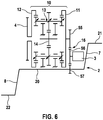
- FIG. 6 shows a preferred embodiment according to a fifth embodiment of the invention.
- the crankshaft 20 and the chainring 4 there is a non-coaxial arrangement of the crankshaft 20 and the chainring 4.
- a central axis of the chainring 4 is parallel to the crankshaft 20.
- the electric drive 3 drives the middle one Gear 56 on.
- the gear 57 is arranged on the crankshaft 20 and meshes with the gear 56.
- the gear 55 is connected to the input element 11 of the continuously variable planetary gear 10.
- the central actuator 14 is freely rotatable.
- the electric drive 3 can also be arranged in other positions, for example on the crankshaft 20 or on the gear 55.
- the electric drive 3 and the crankshaft 20 can also swap their positions, so that the electric drive 3 with gear 57 and the Crankshaft 20 is connected to gear 56.
- any number of spur gear stages can be used for the connection from the crankshaft 20 to the continuously variable planetary gear 10.
- the electric drive 3 can be arranged via a further spur gear stage above gear 55 and without connection to gear 56.
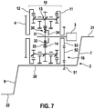
- Figure 7 shows a sixth preferred embodiment of the invention.
- the electric drive 3 is arranged coaxially to the central axis of chainring 4 and to the central axis of the continuously variable planetary gear 10 and connected to the continuously variable planetary gear 10 via an additional conventional planetary gear 30.
- An output (ring gear 33) of the conventional planetary gear 30 is connected to the central actuator 14 or the sun gear of the continuously variable planetary gear 10.
- the sun gear or central actuator 14 of the continuously variable planetary gear 10 is designed as a ring gear 33 for the conventional planetary gear 30.
- the conventional planetary gear 30 is arranged within the central actuator 14 (sun gear).
- the crankshaft 20 and the central axis of the chainring 4 are again not coaxial, but offset parallel to one another. With this arrangement, a high ground clearance can be achieved in particular on the crank drive, since the electric drive 3 and the gear shift are arranged above the crankshaft 20.
- FIG 8 shows a seventh preferred embodiment of the invention.
- the seventh exemplary embodiment has a first conventional planetary gear 30, a second conventional planetary gear 40 and the continuously variable planetary gear 10.
- the first conventional planetary gear 30 is arranged at the entrance to the continuously variable planetary gear 10.
- the second conventional planetary gear 40 with sun gear 41, planet 42 and ring gear 43 is stepless at the output of the adjustable planetary gear 10 is arranged.
- the second conventional planetary gear 40 is connected to the chainring 4 via its sun gear 41.
- the sun gear 31 of the first conventional planetary gear 30 is connected to the crankshaft 20 via a spur gear toothing 16 with gear wheels 51, 52.
- the electric drive 3 is connected to the ring gear 33 of the first conventional planetary gear 30 via a second spur gear toothing 17.
- the central axis of the chainring 4 is in turn offset parallel to the crankshaft 20.
- This exemplary embodiment also has a very compact structure.
- the first conventional planetary gear 30 in combination with the spur gear 16 advantageously increases the input speed for the continuously variable planetary gear 10 and advantageously reduces the input torque. This results in a more compact design for the continuously variable planetary gear 10.
- a speed which is too high at the output of the continuously variable planetary gear 10 for the chainring 4 is suitably reduced again by the second conventional planetary gear 40.
- Figure 9 shows an eighth embodiment of the invention.
- the electric drive 3 is arranged rotated through 90 ° to the crankshaft 20.
- a worm gear 61 with worm 62 and worm wheel 63 is provided, which connects an input element 11 for the continuously variable planetary gear 10 to the electric drive 3.
- the low noise development of worm gears is particularly advantageous here compared to spur gear or planetary gears. Due to the possible high transmission ratio of the worm gear 61 in one step, a particularly compact motor with high speed and low torque can be used.
- the electric drive 3 can in principle assume any angular position around the crankshaft 20 over the circumference of the worm wheel.
- FIG. 10 shows a ninth preferred embodiment of the invention.
- the crank mechanism 2 of the ninth exemplary embodiment essentially corresponds to that of the eighth exemplary embodiment, a spur gear stage being additionally provided between the worm gear 61 and the input element 11 for the continuously variable planetary gear 10 and between the output element 12 for the continuously variable planetary gear 10 and chainring 4.
- This has the advantage that the electric drive 3 can be arranged centrally along the crankshaft 20 for a particularly compact construction.
- the electric drive 3 and the continuously variable planetary gear 10 can take almost any angle to one another around the crankshaft 20.
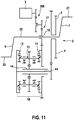
- FIG 11 shows a tenth embodiment of the invention.
- an output element 12 for the continuously variable planetary gear 10 is connected via a central shaft 44 of the continuously variable planetary gear 10 to the chainring 4 on the side of the input element 11 for the continuously variable planetary gear 10.
- the input and output of the continuously variable planetary gear 10 are thus on the same side.
- the continuously variable planetary gear 10 is again not arranged coaxially with the crankshaft 20.
- the further spur gear stage for connecting the output shaft of the continuously variable planetary gear 10 to the chainring 4 can alternatively also be replaced by a belt drive not according to the invention.
- the advantage of a belt drive is the low noise emission and the high efficiency.
Landscapes
- Engineering & Computer Science (AREA)
- Chemical & Material Sciences (AREA)
- Combustion & Propulsion (AREA)
- Transportation (AREA)
- Mechanical Engineering (AREA)
- Transmission Devices (AREA)
Claims (9)
- Véhicule pouvant être propulsé par la force d'un moteur et/ou la force de pédales, notamment bicyclette électrique, comprenant- une transmission à manivelle (2) pourvue d'un vilebrequin (20),- un élément mené, qui est un plateau de pédalier (4), qui délivre un couple d'entraînement pour le véhicule,- un mécanisme d'entraînement électrique (3) pourvu d'un engrenage réducteur et- un engrenage planétaire (10) à réglage continu,- un élément de sortie (12) de l'engrenage planétaire à réglage continu transmettant le couple d'entraînement à l'élément mené,caractérisé en ce que- un élément d'entrée (11) de l'engrenage planétaire (10) à réglage continu est relié à la transmission à manivelle (2) et au mécanisme d'entraînement électrique (3), un couple d'entraînement de pédale appliqué par un conducteur et un couple d'entraînement électrique appliqué par le mécanisme d'entraînement électrique (3) étant introduits par le biais du même élément d'entrée (11) de l'engrenage planétaire (10) à réglage continu, de sorte que l'addition des deux couples a lieu avant l'engrenage planétaire à réglage continu.
- Véhicule selon la revendication 1, caractérisé en ce qu'un engrenage, notamment un engrenage droit (16) ou un engrenage planétaire (30) ou un engrenage à vis sans fin (61), est monté en amont de l'engrenage planétaire (10) à réglage continu.
- Véhicule selon l'une des revendications précédentes, caractérisé en ce que le mécanisme d'entraînement électrique (3) se trouve à l'opposé de l'engrenage planétaire (10) à réglage continu sur le vilebrequin (20) d'un angle quelconque, de préférence de 180°.
- Véhicule selon l'une des revendications 1 ou 2, caractérisé en ce que le mécanisme d'entraînement électrique (3) et l'engrenage planétaire (10) à réglage continu sont disposés sur un côté commun du vilebrequin (20) .
- Véhicule selon l'une des revendications précédentes, caractérisé en ce que le mécanisme d'entraînement électrique (3) est disposé dans le sens radial à l'intérieur ou dans le sens radial à l'extérieur de l'engrenage planétaire (10) à réglage continu.
- Véhicule selon l'une des revendications précédentes, caractérisé en ce que le vilebrequin (20) et un axe central de l'élément mené se séparent et sont notamment parallèles l'un à l'autre.
- Véhicule selon l'une des revendications précédentes, caractérisé en ce que le mécanisme d'entraînement électrique (3) est relié à un engrenage planétaire (30) conventionnel, un élément mené de l'engrenage planétaire (30) conventionnel étant relié à l'engrenage planétaire (10) à réglage continu, notamment à l'organe de commande central ou à la roue solaire (40).
- Véhicule selon l'une des revendications précédentes, caractérisé en ce que l'élément mené est disposé en étant monté en rotation libre sur un arbre creux qui entoure le vilebrequin (20).
- Véhicule selon l'une des revendications précédentes, caractérisé en ce que l'élément mené est disposé sur le côté de l'élément d'entrée (11) de l'engrenage planétaire (10) à réglage continu.
Applications Claiming Priority (3)
| Application Number | Priority Date | Filing Date | Title |
|---|---|---|---|
| DE102013216750 | 2013-08-23 | ||
| DE102013220299.7A DE102013220299A1 (de) | 2013-08-23 | 2013-10-08 | Fahrzeug mit elektrischem Hilfsantrieb und stufenlos verstellbarem Planetengetriebe |
| PCT/EP2014/064609 WO2015024701A1 (fr) | 2013-08-23 | 2014-07-08 | Véhicule comportant un entraînement d'assistance électrique et une transmission à trains épicycloïdaux à variation continue |
Publications (2)
| Publication Number | Publication Date |
|---|---|
| EP3036151A1 EP3036151A1 (fr) | 2016-06-29 |
| EP3036151B1 true EP3036151B1 (fr) | 2020-02-26 |
Family
ID=52446852
Family Applications (1)
| Application Number | Title | Priority Date | Filing Date |
|---|---|---|---|
| EP14736405.3A Active EP3036151B1 (fr) | 2013-08-23 | 2014-07-08 | Véhicule comportant un entraînement d'assistance électrique et une transmission à trains épicycloïdaux à variation continue |
Country Status (5)
| Country | Link |
|---|---|
| US (1) | US9908588B2 (fr) |
| EP (1) | EP3036151B1 (fr) |
| DE (1) | DE102013220299A1 (fr) |
| TW (1) | TWI642592B (fr) |
| WO (1) | WO2015024701A1 (fr) |
Families Citing this family (26)
| Publication number | Priority date | Publication date | Assignee | Title |
|---|---|---|---|---|
| DE102013206713A1 (de) * | 2013-04-15 | 2014-10-16 | Robert Bosch Gmbh | Motorisch und mit Muskelkraft betreibbares Fahrzeug |
| DE102014106591A1 (de) * | 2014-05-09 | 2015-11-12 | Lsp Innovative Automotive Systems Gmbh | Elektrisches Antriebssystem für ein Fahrzeug, insbesondere ein batteriegetriebenes E-Bike, S-Pedelec, E-Bike mit Steuerung in verschiedenen Betriebsmodi |
| TWI582010B (zh) * | 2015-04-22 | 2017-05-11 | Bicycle pedal with auxiliary power trigger function | |
| JP6420199B2 (ja) * | 2015-04-28 | 2018-11-07 | 株式会社シマノ | 自転車用装置 |
| DE102015208245A1 (de) * | 2015-05-05 | 2016-11-10 | Robert Bosch Gmbh | Anordnung, insbesondere elektrisch und/oder mit Muskelkraft antreibbares Fahrzeug mit stufenloser Schaltung |
| DE102015222062A1 (de) * | 2015-11-10 | 2017-05-11 | Robert Bosch Gmbh | Reibringgetriebe, Antrieb und Fahrzeug |
| DE102016225165B4 (de) | 2016-12-15 | 2025-09-11 | Zf Friedrichshafen Ag | Getriebe und Tretlager für ein Fahrrad |
| DE102016225158B4 (de) | 2016-12-15 | 2025-08-21 | Zf Friedrichshafen Ag | Getriebe für ein Fahrrad, Tretlager sowie Fahrrad |
| DE102016225157A1 (de) * | 2016-12-15 | 2018-06-21 | Zf Friedrichshafen Ag | Getriebe für ein Fahrrad |
| US20190359288A1 (en) * | 2016-12-29 | 2019-11-28 | Tae Hwan Ha | Multi-stage transmission bicycle |
| CN106945777A (zh) * | 2017-04-19 | 2017-07-14 | 常州机电职业技术学院 | 人电混合动力驱动装置 |
| CN112810746B (zh) * | 2017-05-23 | 2022-04-29 | 马勒国际有限公司 | 具有功率分流的电动自行车 |
| DE102017216502A1 (de) * | 2017-07-19 | 2019-01-24 | Robert Bosch Gmbh | Antriebsanordnung und Fahrzeug |
| DE102017212347A1 (de) | 2017-07-19 | 2019-01-24 | Robert Bosch Gmbh | Tretlagerantrieb eines Fahrrads |
| DE102017219607A1 (de) | 2017-11-06 | 2019-05-09 | Zf Friedrichshafen Ag | Antriebsanordnung eines Pedelecs |
| DE102017219602B4 (de) | 2017-11-06 | 2025-07-17 | Zf Friedrichshafen Ag | Antriebsanordnung eines Pedelecs |
| BE1026057B1 (fr) * | 2018-03-02 | 2019-09-30 | E2 Drives Sa | Groupe motopropulseur pour véhicule à pédales |
| KR101961589B1 (ko) * | 2018-03-08 | 2019-03-22 | 손순영 | 변속모터와 유성기어 메카니즘을 이용한 자전거용 변속장치 |
| DE102018217097A1 (de) * | 2018-10-05 | 2020-04-09 | Zf Friedrichshafen Ag | Antriebsanordnung für ein Fahrrad oder Pedelec |
| NO349294B1 (en) * | 2019-12-19 | 2025-12-01 | Mont Invest 30 As | Pedally propelled vehicle drive system |
| CN112519949A (zh) * | 2020-11-06 | 2021-03-19 | 广州理工学院 | 一种助步车电源系统 |
| GB2602447A (en) * | 2020-12-16 | 2022-07-06 | Johnston Edward | Gear system, pedal cycle, and method of retrofitting gear system |
| DE102021207255A1 (de) * | 2021-07-08 | 2023-01-12 | Brose Antriebstechnik GmbH & Co. Kommanditgesellschaft, Berlin | Antriebssystem für ein Elektrofahrrad mit Notlaufbetrieb und Steuerungsverfahren |
| GB202203112D0 (en) * | 2022-03-07 | 2022-04-20 | Ebike Systems Ltd | Electrically-assisted pedal cycles |
| NO20240930A1 (en) * | 2024-09-12 | 2026-03-13 | Mont Invest 30 As | Pedally propelled vehicle drive system |
| FR3166365A1 (fr) | 2024-09-16 | 2026-03-20 | Opynov | Dispositif d’entrainement electrique pour vehicule roulant |
Family Cites Families (10)
| Publication number | Priority date | Publication date | Assignee | Title |
|---|---|---|---|---|
| US5167591A (en) | 1988-05-06 | 1992-12-01 | Ben Cowan | Variable speed transmission |
| US7011600B2 (en) | 2003-02-28 | 2006-03-14 | Fallbrook Technologies Inc. | Continuously variable transmission |
| ES2290637T3 (es) * | 2004-09-29 | 2008-02-16 | Nexxtdrive Limited | Cubo o buje que incorpora un sistema de transmision de relacion variable. |
| CN102943855B (zh) | 2007-04-24 | 2016-01-27 | 福博科技术公司 | 电力牵引传动装置 |
| CN201179951Y (zh) | 2007-12-25 | 2009-01-14 | 福斯特资产有限公司 | 带有行星变速机构的蜗轮蜗杆传动装置 |
| DE102008031438A1 (de) * | 2008-07-04 | 2010-02-04 | Clean Mobile Ag | Fahrzeug mit automatischem Getriebe |
| DE202009018521U1 (de) * | 2008-12-11 | 2012-01-18 | Robert Bosch Gmbh | Hybridantrieb für ein Elektrofahrrad |
| DE102009046867A1 (de) * | 2009-11-19 | 2011-05-26 | Robert Bosch Gmbh | Fahrrad |
| NL2005297C2 (nl) | 2010-09-01 | 2012-03-05 | Fides5 B V | Fiets met elektrische aandrijving. |
| JP5649549B2 (ja) * | 2011-10-13 | 2015-01-07 | 株式会社シマノ | 自転車用駆動ユニット |
-
2013
- 2013-10-08 DE DE102013220299.7A patent/DE102013220299A1/de not_active Withdrawn
-
2014
- 2014-07-08 WO PCT/EP2014/064609 patent/WO2015024701A1/fr not_active Ceased
- 2014-07-08 EP EP14736405.3A patent/EP3036151B1/fr active Active
- 2014-07-08 US US14/913,762 patent/US9908588B2/en active Active
- 2014-08-21 TW TW103128771A patent/TWI642592B/zh not_active IP Right Cessation
Non-Patent Citations (1)
| Title |
|---|
| None * |
Also Published As
| Publication number | Publication date |
|---|---|
| US9908588B2 (en) | 2018-03-06 |
| TWI642592B (zh) | 2018-12-01 |
| DE102013220299A1 (de) | 2015-02-26 |
| WO2015024701A1 (fr) | 2015-02-26 |
| EP3036151A1 (fr) | 2016-06-29 |
| US20160221635A1 (en) | 2016-08-04 |
| TW201512028A (zh) | 2015-04-01 |
Similar Documents
| Publication | Publication Date | Title |
|---|---|---|
| WO2015024701A1 (fr) | Véhicule comportant un entraînement d'assistance électrique et une transmission à trains épicycloïdaux à variation continue | |
| EP2986492B1 (fr) | Véhicule entraînable par un moteur et par la force musculaire | |
| EP3790789B1 (fr) | Système d'entraînement | |
| EP2986493B1 (fr) | Véhicule entraînable par un moteur et par la force musculaire | |
| EP3209543B1 (fr) | Mécanisme de transmission réglable à anneau de friction pour véhicule pouvant être mu par la force d'un moteur et/ou d'un pédalier | |
| EP3689730B1 (fr) | Systéme d'entraînement et véhicule | |
| DE102012023551A1 (de) | Stufenloses Tretlagergetriebe für Fahrräder, Pedelecs und E-Bikes mit optional integrierbarem Elektromotor | |
| EP2743543B1 (fr) | Engrenage d'embrayage à division de puissance d'un entraînement de véhicule | |
| EP3509935B1 (fr) | Système de propulsion et véhicule | |
| WO2012113468A1 (fr) | Ensemble de propulsion d'un véhicule hybride | |
| EP3209544B1 (fr) | Transmission à anneau de friction disposé coaxialement pour un véhicule actionnable par une force motrice et/ou une force de pédales | |
| DE102009054480A1 (de) | Antriebsvorrichtung für ein Fahrrad | |
| DE102015208245A1 (de) | Anordnung, insbesondere elektrisch und/oder mit Muskelkraft antreibbares Fahrzeug mit stufenloser Schaltung | |
| DE102023202060A1 (de) | Antriebseinrichtung für ein muskelkraftbetriebenes Fahrzeug | |
| DE102018205126B4 (de) | Torque Vectoring-Überlagerungseinheit für ein Differenzialausgleichsgetriebe | |
| DE102015106564B3 (de) | Antriebsanordnung für ein Fahrrad | |
| EP4463361B1 (fr) | Entraînement de bicyclette et bicyclette | |
| DE102012023150A1 (de) | Stufenloses Tretlagergetriebe für Fahrräder, Pedelecs und E-Bikes mit optional integrierbarem Elektromotor | |
| DE102012206435B4 (de) | Antriebsanordnung für ein Fahrzeug | |
| EP4440918B1 (fr) | Entraînement de bicyclette et bicyclette | |
| DE102024112070B4 (de) | Antriebsvorrichtung für ein Fahrrad mit einem stufenlos verstellbaren Getriebe | |
| DE102024113872B4 (de) | Antriebsvorrichtung für ein Fahrrad mit einem stufenlos verstellbaren Getriebe | |
| DE102024112067B4 (de) | Antriebsvorrichtung für ein Fahrrad mit einem stufenlos verstellbaren Getriebe | |
| WO2018001622A1 (fr) | Boîte de vitesses de véhicule automobile, et chaîne cinématique de véhicule automobile | |
| EP4660066A1 (fr) | Système d'entraînement d'une bicyclette électrique |
Legal Events
| Date | Code | Title | Description |
|---|---|---|---|
| PUAI | Public reference made under article 153(3) epc to a published international application that has entered the european phase |
Free format text: ORIGINAL CODE: 0009012 |
|
| 17P | Request for examination filed |
Effective date: 20160323 |
|
| AK | Designated contracting states |
Kind code of ref document: A1 Designated state(s): AL AT BE BG CH CY CZ DE DK EE ES FI FR GB GR HR HU IE IS IT LI LT LU LV MC MK MT NL NO PL PT RO RS SE SI SK SM TR |
|
| AX | Request for extension of the european patent |
Extension state: BA ME |
|
| DAX | Request for extension of the european patent (deleted) | ||
| STAA | Information on the status of an ep patent application or granted ep patent |
Free format text: STATUS: EXAMINATION IS IN PROGRESS |
|
| 17Q | First examination report despatched |
Effective date: 20180619 |
|
| GRAP | Despatch of communication of intention to grant a patent |
Free format text: ORIGINAL CODE: EPIDOSNIGR1 |
|
| STAA | Information on the status of an ep patent application or granted ep patent |
Free format text: STATUS: GRANT OF PATENT IS INTENDED |
|
| INTG | Intention to grant announced |
Effective date: 20191119 |
|
| GRAS | Grant fee paid |
Free format text: ORIGINAL CODE: EPIDOSNIGR3 |
|
| GRAA | (expected) grant |
Free format text: ORIGINAL CODE: 0009210 |
|
| STAA | Information on the status of an ep patent application or granted ep patent |
Free format text: STATUS: THE PATENT HAS BEEN GRANTED |
|
| AK | Designated contracting states |
Kind code of ref document: B1 Designated state(s): AL AT BE BG CH CY CZ DE DK EE ES FI FR GB GR HR HU IE IS IT LI LT LU LV MC MK MT NL NO PL PT RO RS SE SI SK SM TR |
|
| REG | Reference to a national code |
Ref country code: GB Ref legal event code: FG4D Free format text: NOT ENGLISH |
|
| REG | Reference to a national code |
Ref country code: CH Ref legal event code: EP |
|
| REG | Reference to a national code |
Ref country code: DE Ref legal event code: R096 Ref document number: 502014013693 Country of ref document: DE |
|
| REG | Reference to a national code |
Ref country code: AT Ref legal event code: REF Ref document number: 1237316 Country of ref document: AT Kind code of ref document: T Effective date: 20200315 |
|
| REG | Reference to a national code |
Ref country code: IE Ref legal event code: FG4D Free format text: LANGUAGE OF EP DOCUMENT: GERMAN |
|
| RAP2 | Party data changed (patent owner data changed or rights of a patent transferred) |
Owner name: ROBERT BOSCH GMBH |
|
| PG25 | Lapsed in a contracting state [announced via postgrant information from national office to epo] |
Ref country code: RS Free format text: LAPSE BECAUSE OF FAILURE TO SUBMIT A TRANSLATION OF THE DESCRIPTION OR TO PAY THE FEE WITHIN THE PRESCRIBED TIME-LIMIT Effective date: 20200226 Ref country code: NO Free format text: LAPSE BECAUSE OF FAILURE TO SUBMIT A TRANSLATION OF THE DESCRIPTION OR TO PAY THE FEE WITHIN THE PRESCRIBED TIME-LIMIT Effective date: 20200526 Ref country code: FI Free format text: LAPSE BECAUSE OF FAILURE TO SUBMIT A TRANSLATION OF THE DESCRIPTION OR TO PAY THE FEE WITHIN THE PRESCRIBED TIME-LIMIT Effective date: 20200226 |
|
| REG | Reference to a national code |
Ref country code: NL Ref legal event code: MP Effective date: 20200226 |
|
| REG | Reference to a national code |
Ref country code: LT Ref legal event code: MG4D |
|
| PG25 | Lapsed in a contracting state [announced via postgrant information from national office to epo] |
Ref country code: SE Free format text: LAPSE BECAUSE OF FAILURE TO SUBMIT A TRANSLATION OF THE DESCRIPTION OR TO PAY THE FEE WITHIN THE PRESCRIBED TIME-LIMIT Effective date: 20200226 Ref country code: LV Free format text: LAPSE BECAUSE OF FAILURE TO SUBMIT A TRANSLATION OF THE DESCRIPTION OR TO PAY THE FEE WITHIN THE PRESCRIBED TIME-LIMIT Effective date: 20200226 Ref country code: HR Free format text: LAPSE BECAUSE OF FAILURE TO SUBMIT A TRANSLATION OF THE DESCRIPTION OR TO PAY THE FEE WITHIN THE PRESCRIBED TIME-LIMIT Effective date: 20200226 Ref country code: IS Free format text: LAPSE BECAUSE OF FAILURE TO SUBMIT A TRANSLATION OF THE DESCRIPTION OR TO PAY THE FEE WITHIN THE PRESCRIBED TIME-LIMIT Effective date: 20200626 Ref country code: BG Free format text: LAPSE BECAUSE OF FAILURE TO SUBMIT A TRANSLATION OF THE DESCRIPTION OR TO PAY THE FEE WITHIN THE PRESCRIBED TIME-LIMIT Effective date: 20200526 Ref country code: GR Free format text: LAPSE BECAUSE OF FAILURE TO SUBMIT A TRANSLATION OF THE DESCRIPTION OR TO PAY THE FEE WITHIN THE PRESCRIBED TIME-LIMIT Effective date: 20200527 |
|
| PG25 | Lapsed in a contracting state [announced via postgrant information from national office to epo] |
Ref country code: NL Free format text: LAPSE BECAUSE OF FAILURE TO SUBMIT A TRANSLATION OF THE DESCRIPTION OR TO PAY THE FEE WITHIN THE PRESCRIBED TIME-LIMIT Effective date: 20200226 |
|
| PG25 | Lapsed in a contracting state [announced via postgrant information from national office to epo] |
Ref country code: RO Free format text: LAPSE BECAUSE OF FAILURE TO SUBMIT A TRANSLATION OF THE DESCRIPTION OR TO PAY THE FEE WITHIN THE PRESCRIBED TIME-LIMIT Effective date: 20200226 Ref country code: SK Free format text: LAPSE BECAUSE OF FAILURE TO SUBMIT A TRANSLATION OF THE DESCRIPTION OR TO PAY THE FEE WITHIN THE PRESCRIBED TIME-LIMIT Effective date: 20200226 Ref country code: CZ Free format text: LAPSE BECAUSE OF FAILURE TO SUBMIT A TRANSLATION OF THE DESCRIPTION OR TO PAY THE FEE WITHIN THE PRESCRIBED TIME-LIMIT Effective date: 20200226 Ref country code: PT Free format text: LAPSE BECAUSE OF FAILURE TO SUBMIT A TRANSLATION OF THE DESCRIPTION OR TO PAY THE FEE WITHIN THE PRESCRIBED TIME-LIMIT Effective date: 20200719 Ref country code: DK Free format text: LAPSE BECAUSE OF FAILURE TO SUBMIT A TRANSLATION OF THE DESCRIPTION OR TO PAY THE FEE WITHIN THE PRESCRIBED TIME-LIMIT Effective date: 20200226 Ref country code: ES Free format text: LAPSE BECAUSE OF FAILURE TO SUBMIT A TRANSLATION OF THE DESCRIPTION OR TO PAY THE FEE WITHIN THE PRESCRIBED TIME-LIMIT Effective date: 20200226 Ref country code: LT Free format text: LAPSE BECAUSE OF FAILURE TO SUBMIT A TRANSLATION OF THE DESCRIPTION OR TO PAY THE FEE WITHIN THE PRESCRIBED TIME-LIMIT Effective date: 20200226 Ref country code: EE Free format text: LAPSE BECAUSE OF FAILURE TO SUBMIT A TRANSLATION OF THE DESCRIPTION OR TO PAY THE FEE WITHIN THE PRESCRIBED TIME-LIMIT Effective date: 20200226 Ref country code: SM Free format text: LAPSE BECAUSE OF FAILURE TO SUBMIT A TRANSLATION OF THE DESCRIPTION OR TO PAY THE FEE WITHIN THE PRESCRIBED TIME-LIMIT Effective date: 20200226 |
|
| PGFP | Annual fee paid to national office [announced via postgrant information from national office to epo] |
Ref country code: GB Payment date: 20200724 Year of fee payment: 7 Ref country code: FR Payment date: 20200727 Year of fee payment: 7 |
|
| REG | Reference to a national code |
Ref country code: DE Ref legal event code: R097 Ref document number: 502014013693 Country of ref document: DE |
|
| PGFP | Annual fee paid to national office [announced via postgrant information from national office to epo] |
Ref country code: IT Payment date: 20200731 Year of fee payment: 7 |
|
| PLBE | No opposition filed within time limit |
Free format text: ORIGINAL CODE: 0009261 |
|
| STAA | Information on the status of an ep patent application or granted ep patent |
Free format text: STATUS: NO OPPOSITION FILED WITHIN TIME LIMIT |
|
| 26N | No opposition filed |
Effective date: 20201127 |
|
| PG25 | Lapsed in a contracting state [announced via postgrant information from national office to epo] |
Ref country code: MC Free format text: LAPSE BECAUSE OF FAILURE TO SUBMIT A TRANSLATION OF THE DESCRIPTION OR TO PAY THE FEE WITHIN THE PRESCRIBED TIME-LIMIT Effective date: 20200226 Ref country code: SI Free format text: LAPSE BECAUSE OF FAILURE TO SUBMIT A TRANSLATION OF THE DESCRIPTION OR TO PAY THE FEE WITHIN THE PRESCRIBED TIME-LIMIT Effective date: 20200226 Ref country code: PL Free format text: LAPSE BECAUSE OF FAILURE TO SUBMIT A TRANSLATION OF THE DESCRIPTION OR TO PAY THE FEE WITHIN THE PRESCRIBED TIME-LIMIT Effective date: 20200226 |
|
| REG | Reference to a national code |
Ref country code: CH Ref legal event code: PL |
|
| REG | Reference to a national code |
Ref country code: BE Ref legal event code: MM Effective date: 20200731 |
|
| PG25 | Lapsed in a contracting state [announced via postgrant information from national office to epo] |
Ref country code: LU Free format text: LAPSE BECAUSE OF NON-PAYMENT OF DUE FEES Effective date: 20200708 Ref country code: CH Free format text: LAPSE BECAUSE OF NON-PAYMENT OF DUE FEES Effective date: 20200731 Ref country code: LI Free format text: LAPSE BECAUSE OF NON-PAYMENT OF DUE FEES Effective date: 20200731 |
|
| PG25 | Lapsed in a contracting state [announced via postgrant information from national office to epo] |
Ref country code: BE Free format text: LAPSE BECAUSE OF NON-PAYMENT OF DUE FEES Effective date: 20200731 |
|
| PG25 | Lapsed in a contracting state [announced via postgrant information from national office to epo] |
Ref country code: IE Free format text: LAPSE BECAUSE OF NON-PAYMENT OF DUE FEES Effective date: 20200708 |
|
| REG | Reference to a national code |
Ref country code: AT Ref legal event code: MM01 Ref document number: 1237316 Country of ref document: AT Kind code of ref document: T Effective date: 20200708 |
|
| PG25 | Lapsed in a contracting state [announced via postgrant information from national office to epo] |
Ref country code: AT Free format text: LAPSE BECAUSE OF NON-PAYMENT OF DUE FEES Effective date: 20200708 |
|
| GBPC | Gb: european patent ceased through non-payment of renewal fee |
Effective date: 20210708 |
|
| PG25 | Lapsed in a contracting state [announced via postgrant information from national office to epo] |
Ref country code: GB Free format text: LAPSE BECAUSE OF NON-PAYMENT OF DUE FEES Effective date: 20210708 |
|
| PG25 | Lapsed in a contracting state [announced via postgrant information from national office to epo] |
Ref country code: TR Free format text: LAPSE BECAUSE OF FAILURE TO SUBMIT A TRANSLATION OF THE DESCRIPTION OR TO PAY THE FEE WITHIN THE PRESCRIBED TIME-LIMIT Effective date: 20200226 Ref country code: MT Free format text: LAPSE BECAUSE OF FAILURE TO SUBMIT A TRANSLATION OF THE DESCRIPTION OR TO PAY THE FEE WITHIN THE PRESCRIBED TIME-LIMIT Effective date: 20200226 Ref country code: FR Free format text: LAPSE BECAUSE OF NON-PAYMENT OF DUE FEES Effective date: 20210731 Ref country code: CY Free format text: LAPSE BECAUSE OF FAILURE TO SUBMIT A TRANSLATION OF THE DESCRIPTION OR TO PAY THE FEE WITHIN THE PRESCRIBED TIME-LIMIT Effective date: 20200226 |
|
| PG25 | Lapsed in a contracting state [announced via postgrant information from national office to epo] |
Ref country code: MK Free format text: LAPSE BECAUSE OF FAILURE TO SUBMIT A TRANSLATION OF THE DESCRIPTION OR TO PAY THE FEE WITHIN THE PRESCRIBED TIME-LIMIT Effective date: 20200226 Ref country code: AL Free format text: LAPSE BECAUSE OF FAILURE TO SUBMIT A TRANSLATION OF THE DESCRIPTION OR TO PAY THE FEE WITHIN THE PRESCRIBED TIME-LIMIT Effective date: 20200226 |
|
| PG25 | Lapsed in a contracting state [announced via postgrant information from national office to epo] |
Ref country code: IT Free format text: LAPSE BECAUSE OF NON-PAYMENT OF DUE FEES Effective date: 20210708 |
|
| PGFP | Annual fee paid to national office [announced via postgrant information from national office to epo] |
Ref country code: DE Payment date: 20250924 Year of fee payment: 12 |