EP3036029B1 - Verfahren zur erhöhung der effizienz einer ölabsorption durch einen schwamm - Google Patents
Verfahren zur erhöhung der effizienz einer ölabsorption durch einen schwamm Download PDFInfo
- Publication number
- EP3036029B1 EP3036029B1 EP14838007.4A EP14838007A EP3036029B1 EP 3036029 B1 EP3036029 B1 EP 3036029B1 EP 14838007 A EP14838007 A EP 14838007A EP 3036029 B1 EP3036029 B1 EP 3036029B1
- Authority
- EP
- European Patent Office
- Prior art keywords
- overhead vapor
- hot
- stripper
- cold
- net overhead
- Prior art date
- Legal status (The legal status is an assumption and is not a legal conclusion. Google has not performed a legal analysis and makes no representation as to the accuracy of the status listed.)
- Not-in-force
Links
Images

Classifications
-
- B—PERFORMING OPERATIONS; TRANSPORTING
- B01—PHYSICAL OR CHEMICAL PROCESSES OR APPARATUS IN GENERAL
- B01D—SEPARATION
- B01D53/00—Separation of gases or vapours; Recovering vapours of volatile solvents from gases; Chemical or biological purification of waste gases, e.g. engine exhaust gases, smoke, fumes, flue gases, aerosols
- B01D53/14—Separation of gases or vapours; Recovering vapours of volatile solvents from gases; Chemical or biological purification of waste gases, e.g. engine exhaust gases, smoke, fumes, flue gases, aerosols by absorption
-
- B—PERFORMING OPERATIONS; TRANSPORTING
- B01—PHYSICAL OR CHEMICAL PROCESSES OR APPARATUS IN GENERAL
- B01D—SEPARATION
- B01D53/00—Separation of gases or vapours; Recovering vapours of volatile solvents from gases; Chemical or biological purification of waste gases, e.g. engine exhaust gases, smoke, fumes, flue gases, aerosols
- B01D53/34—Chemical or biological purification of waste gases
- B01D53/96—Regeneration, reactivation or recycling of reactants
-
- C—CHEMISTRY; METALLURGY
- C01—INORGANIC CHEMISTRY
- C01B—NON-METALLIC ELEMENTS; COMPOUNDS THEREOF; METALLOIDS OR COMPOUNDS THEREOF NOT COVERED BY SUBCLASS C01C
- C01B3/00—Hydrogen; Gaseous mixtures containing hydrogen; Separation of hydrogen from mixtures containing it; Purification of hydrogen; Reversible storage of hydrogen
- C01B3/50—Separation of hydrogen or hydrogen-containing gases from gaseous mixtures, e.g. purification
- C01B3/52—Separation of hydrogen or hydrogen-containing gases from gaseous mixtures, e.g. purification by contacting with liquids; Regeneration of used liquids
-
- C—CHEMISTRY; METALLURGY
- C10—PETROLEUM, GAS OR COKE INDUSTRIES; TECHNICAL GASES CONTAINING CARBON MONOXIDE; FUELS; LUBRICANTS; PEAT
- C10G—CRACKING HYDROCARBON OILS; PRODUCTION OF LIQUID HYDROCARBON MIXTURES, e.g. BY DESTRUCTIVE HYDROGENATION, OLIGOMERISATION, POLYMERISATION; RECOVERY OF HYDROCARBON OILS FROM OIL-SHALE, OIL-SAND, OR GASES; REFINING MIXTURES MAINLY CONSISTING OF HYDROCARBONS; REFORMING OF NAPHTHA; MINERAL WAXES
- C10G5/00—Recovery of liquid hydrocarbon mixtures from gases, e.g. natural gas
- C10G5/04—Recovery of liquid hydrocarbon mixtures from gases, e.g. natural gas with liquid absorbents
-
- C—CHEMISTRY; METALLURGY
- C10—PETROLEUM, GAS OR COKE INDUSTRIES; TECHNICAL GASES CONTAINING CARBON MONOXIDE; FUELS; LUBRICANTS; PEAT
- C10G—CRACKING HYDROCARBON OILS; PRODUCTION OF LIQUID HYDROCARBON MIXTURES, e.g. BY DESTRUCTIVE HYDROGENATION, OLIGOMERISATION, POLYMERISATION; RECOVERY OF HYDROCARBON OILS FROM OIL-SHALE, OIL-SAND, OR GASES; REFINING MIXTURES MAINLY CONSISTING OF HYDROCARBONS; REFORMING OF NAPHTHA; MINERAL WAXES
- C10G7/00—Distillation of hydrocarbon oils
- C10G7/02—Stabilising gasoline by removing gases by fractioning
-
- C—CHEMISTRY; METALLURGY
- C10—PETROLEUM, GAS OR COKE INDUSTRIES; TECHNICAL GASES CONTAINING CARBON MONOXIDE; FUELS; LUBRICANTS; PEAT
- C10G—CRACKING HYDROCARBON OILS; PRODUCTION OF LIQUID HYDROCARBON MIXTURES, e.g. BY DESTRUCTIVE HYDROGENATION, OLIGOMERISATION, POLYMERISATION; RECOVERY OF HYDROCARBON OILS FROM OIL-SHALE, OIL-SAND, OR GASES; REFINING MIXTURES MAINLY CONSISTING OF HYDROCARBONS; REFORMING OF NAPHTHA; MINERAL WAXES
- C10G70/00—Working-up undefined normally gaseous mixtures obtained by processes covered by groups C10G9/00, C10G11/00, C10G15/00, C10G47/00, C10G51/00
- C10G70/04—Working-up undefined normally gaseous mixtures obtained by processes covered by groups C10G9/00, C10G11/00, C10G15/00, C10G47/00, C10G51/00 by physical processes
- C10G70/06—Working-up undefined normally gaseous mixtures obtained by processes covered by groups C10G9/00, C10G11/00, C10G15/00, C10G47/00, C10G51/00 by physical processes by gas-liquid contact
-
- C—CHEMISTRY; METALLURGY
- C10—PETROLEUM, GAS OR COKE INDUSTRIES; TECHNICAL GASES CONTAINING CARBON MONOXIDE; FUELS; LUBRICANTS; PEAT
- C10L—FUELS NOT OTHERWISE PROVIDED FOR; NATURAL GAS; SYNTHETIC NATURAL GAS OBTAINED BY PROCESSES NOT COVERED BY SUBCLASSES C10G OR C10K; LIQUIFIED PETROLEUM GAS; USE OF ADDITIVES TO FUELS OR FIRES; FIRE-LIGHTERS
- C10L3/00—Gaseous fuels; Natural gas; Synthetic natural gas obtained by processes not covered by subclass C10G, C10K; Liquefied petroleum gas
- C10L3/12—Liquefied petroleum gas
-
- C—CHEMISTRY; METALLURGY
- C01—INORGANIC CHEMISTRY
- C01B—NON-METALLIC ELEMENTS; COMPOUNDS THEREOF; METALLOIDS OR COMPOUNDS THEREOF NOT COVERED BY SUBCLASS C01C
- C01B2203/00—Integrated processes for the production of hydrogen or synthesis gas
- C01B2203/04—Integrated processes for the production of hydrogen or synthesis gas containing a purification step for the hydrogen or the synthesis gas
- C01B2203/0415—Purification by absorption in liquids
-
- C—CHEMISTRY; METALLURGY
- C10—PETROLEUM, GAS OR COKE INDUSTRIES; TECHNICAL GASES CONTAINING CARBON MONOXIDE; FUELS; LUBRICANTS; PEAT
- C10G—CRACKING HYDROCARBON OILS; PRODUCTION OF LIQUID HYDROCARBON MIXTURES, e.g. BY DESTRUCTIVE HYDROGENATION, OLIGOMERISATION, POLYMERISATION; RECOVERY OF HYDROCARBON OILS FROM OIL-SHALE, OIL-SAND, OR GASES; REFINING MIXTURES MAINLY CONSISTING OF HYDROCARBONS; REFORMING OF NAPHTHA; MINERAL WAXES
- C10G2400/00—Products obtained by processes covered by groups C10G9/00 - C10G69/14
- C10G2400/26—Fuel gas
-
- C—CHEMISTRY; METALLURGY
- C10—PETROLEUM, GAS OR COKE INDUSTRIES; TECHNICAL GASES CONTAINING CARBON MONOXIDE; FUELS; LUBRICANTS; PEAT
- C10G—CRACKING HYDROCARBON OILS; PRODUCTION OF LIQUID HYDROCARBON MIXTURES, e.g. BY DESTRUCTIVE HYDROGENATION, OLIGOMERISATION, POLYMERISATION; RECOVERY OF HYDROCARBON OILS FROM OIL-SHALE, OIL-SAND, OR GASES; REFINING MIXTURES MAINLY CONSISTING OF HYDROCARBONS; REFORMING OF NAPHTHA; MINERAL WAXES
- C10G2400/00—Products obtained by processes covered by groups C10G9/00 - C10G69/14
- C10G2400/28—Propane and butane
Definitions
- US 4,899,015 discloses a process for the recovery and separation of LPG from olefins to gasoline conversion process effluent stream.
- the sponge absorber system is fed with the vapor fraction of a low temperature separator and the lean sponge oil is a C5+ fraction recovered from depropanizer/ debutanizer.
- a first aspect of the invention is a method for improving efficiency of sponge absorption as defined in claim 1.
- the ratio of LPG and hydrogen in the cold flash drum liquid and hot flash drum liquid varies significantly.
- 70-90% of the LPG is present in the cold flash drum liquid, while only 10-30% is present in the hot flash drum liquid .
- the hydrogen present in the combined feed i.e. cold flash drum liquid and hot flash drum liquid
- 20-35% of the hydrogen is present in the cold flash drum liquid, and 65-80% is contained in the hot flash drum liquid.
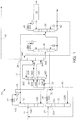
- a process flow for improving sponge absorber efficiency is generally designated 10.
- a cold flash drum liquid 11 is routed to an inlet 12A of a cold stripper 12, and medium pressure steam enters the stripper at inlet 12B.
- Overhead vapor rich in liquid petroleum gas is output from an outlet 12C of the cold stripper 12, and is routed to a first condenser 14 and then to a first drum 16, to cool and at least partially condense the cold stripper overhead vapor stream.
- the liquid portion of the condensed cold stripper overhead from the drum 16 is partially recycled to the cold stripper 12 as a reflux and net liquid is routed to the inlet of deethanizer column 36 via line 17.
- the cold stripper net overhead vapor from drum 16 is routed to a first amine scrubber 18 through a cold stripper net overhead vapor line 20.
- hot flash drum liquid 21 is separately routed to an inlet 22A of a hot stripper 22, and medium pressure steam enters the stripper at inlet 12B.
- Overhead vapor rich in hydrogen is output from an outlet 22C of the hot stripper 22, and is routed to a second condenser 24 and then to a second drum 26, to cool and at least partially condense the hot stripper overhead vapor.
- the liquid portion of the condensed hot stripper overhead from the drum 26 is recycled by routing the hot stripper net overhead liquid through a recycle line 28 to be mixed with the cold flash drum liquid 11 and provided as a feed to the cold stripper 12.
- the hot stripper net overhead vapor is separately routed to a second amine scrubber 30 through a hot stripper overhead vapor line 32.
- the cold stripper net overhead vapor enters the scrubber at an inlet 18A near the bottom and flows upward, while a lean amine enters the scrubber at an inlet 18B near the top and flows downward.
- Preferred lean amines include alkanolamines diethanolamine (DEA), monoethanolamine (MEA), and methyldiethanolamine (MDEA).
- DEA alkanolamines diethanolamine
- MEA monoethanolamine
- MDEA methyldiethanolamine
- the lean amine contacts the cold stripper net overhead vapor, removing contaminants such as hydrogen sulfide and carbon dioxide.
- the resultant "sweetened" cold stripper net overhead vapor is taken out from the top of the first scrubber 18 at an outlet 18C, and a rich amine is taken out from the bottoms at an outlet 18D of the first scrubber.
- the rich amine may undergo regeneration to remove the hydrogen sulfide for processing to generate elemental sulfur.
- the hot stripper net overhead vapor enters the scrubber at an inlet 30A near the bottom and flows upward, while a lean amine enters the scrubber at an inlet 30B near the top and flows downward.
- the amine provided to the second amine scrubber is preferably the same as that provided to the first amine scrubber, but those of skill in the art will recognize that different amines may be used depending on requirements of the second amine scrubber 30.
- the lean amine entering the second amine scrubber 30 contacts the hot stripper net overhead vapor, removing contaminants such as hydrogen sulfide and carbon dioxide.
- the resultant "sweetened" hot stripper net overhead vapor is taken out from the top of the second scrubber 30 at an outlet 30C, and a rich amine is taken out from the bottoms at an outlet 30D.
- the rich amine from the second amine scrubber 30 may undergo regeneration to remove the hydrogen sulfide for processing to generate elemental sulfur.
- a multi-tray sponge absorber 34 includes a first inlet 34A and a second inlet 34B to receive two distinct feeds.
- the first inlet 34A is provided at a tray location near a bottom of the absorber 34, while the second inlet 34B is provided near a center of the absorber.
- an absorber having ten trays may have a first inlet at the tenth (i.e., bottom-most) tray, and the second inlet at the fifth tray.
- the sponge absorber 34 receives the sweetened cold stripper net overhead vapor from the first amine scrubber outlet 18C at the first inlet 34A, and the sweetened hot stripper net overhead vapor from the second amine scrubber outlet 30C at the second inlet 34B, higher up on the sponge absorber than the first inlet 34A.
- Lean sponge oil is fed into the sponge absorber 34 through a lean sponge oil line.
- the lean sponge oil and the sweetened hot and cold stripper net overhead vapor streams are contacted in countercurrent extraction flow patterns.
- the sponge oil absorbs, extracts, and separates a substantial amount of methane and ethane and most of the C 3 , C 4 , C 5 , and C 6 + light hydrocarbons (propane, butane, pentane, hexane, etc.) from the hot and cold stripper net overhead vapor streams.
- the sponge absorber 34 operates at a temperature of 34 to 60°C.
- the effluent gases are withdrawn from the sponge absorber 34 at outlet 34C as off gas through an off gas line 35 from the top of the sponge absorber.
- a stream rich in LPG is extracted from the bottoms of the absorber 34 at outlet 34D
- the LPG-rich cold stripper net overhead vapor stream is provided to the sponge absorber 34 separately from the hydrogen-rich hot stripper net overhead vapor stream, allowing the sponge oil to more easily absorb the LPG.
- the sponge oil requirement was reduced by 34-44% to absorb a similar quantity of LPG, relative to feeding the streams to the sponge absorber together.
- the LPG-rich sponge oil from the sponge absorber 34 bottoms is then routed to a deethanizer 36 and respective equipment, as is known in the art.
- a deethanizer overhead net vapor stream is combined with the hot stripper net overhead vapor or cold stripper net overhead vapor before the net overhead vapor stream is provided to its associated amine scrubber.
- the net overhead vapor stream is recycled to the associated amine scrubber to recover LPG present in the overhead.
- the deethanizer net overhead vapor stream is combined with the cold stripper net overhead vapor stream along the line 20 and introduced into the first amine scrubber 18.
- a debutanizer 38 receives a feed from deethanizer 36 bottoms and separates an LPG stream 40 as a net overhead product and a light naphtha stream 42 as a bottoms product as is known in the art.
- the Light naphtha stream 42 from the debutanizer 38 bottoms is at least partially recycled to the sponge absorber 34 as a sponge oil and partially drawn as net bottoms product from the debutanizer. Additionally, LPG from the debutanizer 38 overhead may be further treated in a caustic treatment process 44. Because of the above-mentioned decrease in the required sponge oil circulation, there is a measurable decrease in the reboiler and condenser duty of both the deethanizer 36 and the debutanizer 38.
- reboiler and condenser duty requirement for both the deethanizer 36 and debutanizer 38 and their associated equipment is reduced by around 20-30% compared to the duty requirements when the hot and cold net overhead vapor streams are combined prior to entering the stripper 34.
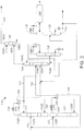
- a different embodiment of the process flow used to increase the efficiency of the sponge absorber is generally designated 110.
- the process flow 110 is consistent in many respects to other device embodiments illustrated and discussed herein including the process flow 10. For this reason, similar element numbers in the 100 series have been used for clarity.
- the process flow 110 of FIG. 2 shows that a cold flash drum liquid 111 is routed to an inlet 112A of a cold stripper 112, and medium pressure steam enters the cold stripper at inlet 112B.
- Overhead vapor rich in liquid petroleum gas from an outlet 112C of the cold stripper 112 is routed to a first condenser 114 and then to a first drum 116, which at least partially condenses the cold stripper overhead vapor stream.
- the liquid portion of the condensed cold stripper overhead from the drum 116 is partially recycled to the cold stripper 112 as a reflux and net liquid is routed to the inlet of deethanizer column 136 via line 117.
- the cold stripper overhead vapor from drum 116 is routed directly to a first inlet 134A of the sponge absorber 134 through a cold stripper net overhead vapor line 120.
- hot flash drum liquid 121 is separately routed to an inlet 122A of a hot stripper 122, and medium pressure steam enters the hot stripper at inlet 122B.
- Overhead vapor rich in hydrogen from an outlet 122C of the hot stripper 122 is routed to a second condenser 124 and then to a second drum 126, to cool and at least partially condense the hot stripper overhead vapor.
- the liquid portion of the condensed hot stripper overhead from the drum 126 is recycled by routing the hot stripper net overhead liquid through a recycle line 128 to be mixed with the cold flash drum liquid 111 and provided as a feed to the cold stripper 112.
- the hot stripper net overhead vapor is separately routed directly to a second inlet 134B of the sponge absorber 134 through a hot stripper net overhead vapor line 132.
- the first inlet 134A of the sponge absorber 134 is provided near a bottom of the absorber, while the second inlet 134B is provided near a center of the absorber, higher up on the sponge absorber than the first inlet 134A.
- an absorber having ten trays may have a first inlet at the tenth (i.e., bottom-most) tray, and the second inlet at the fifth tray.
- the sponge absorber 134 receives the cold stripper net overhead vapor at the first inlet 134A, and the hot stripper net overhead vapor at the second inlet 134B, higher up on the sponge absorber.
- Lean sponge oil is fed into the sponge absorber 134 through a lean sponge oil line.
- the lean sponge oil and the hot and cold stripper net overhead vapors are contacted in countercurrent extraction flow patterns.
- the sponge oil absorbs, extracts, and separates a substantial amount of methane and ethane and most of the C 3 , C 4 , C 5 , and C 6 + light hydrocarbons (propane, butane, pentane, hexane, etc.) from the hot and cold stripper net overhead vapor streams.
- the sponge absorber 134 may operate at a temperature of 34 to 60°C.
- the effluent gases (including hydrogen, methane, ethane, and hydrogen sulfide) are withdrawn from the sponge absorber 134 as off-gas at outlet 134C and are fed into an amine scrubber 150.
- a stream rich in LPG is extracted from the bottoms of the absorber 134 at outlet 134D.
- the off-gas enters the scrubber at inlet 150A near the bottom and flows upward, while a lean amine enters the scrubber at an inlet 150B near the top and flows downward.
- Preferred amines include alkanolamines diethanolamine (DEA), monoethanolamine (MEA), and methyldiethanolamine (MDEA).
- DEA alkanolamines diethanolamine
- MEA monoethanolamine
- MDEA methyldiethanolamine
- the lean amine contacts the off-gas, removing contaminants such as hydrogen sulfide and carbon dioxide.
- the resultant off-gas is taken out from an outlet 150C at the top of the scrubber 150 through off gas line 135, and a rich amine is taken out from the bottoms of the scrubber at an outlet 150D.
- the rich amine may undergo regeneration to remove, for example, the hydrogen sulfide for processing to generate elemental sulfur.
- the LPG-rich sponge oil from the sponge absorber 134 bottoms is then routed to a deethanizer 136 and respective equipment (including a reboiler and a condenser), as is known in the art.
- a deethanizer overhead net vapor stream is combined with the hot stripper net overhead vapor or cold stripper net overhead vapor before the net overhead vapor stream is provided to the sponge absorber 134.
- the net overhead vapor stream is recycled to the sponge absorber to recover LPG present in the overhead.
- the deethanizer overhead vapor stream is combined with the cold stripper net overhead vapor stream along the line 120 and introduced into the sponge absorber 134 at the first inlet 134A.
- a debutanizer 138 receives the feed from the deethanizer 136 bottoms and separates an LPG stream 140 as a net overhead product and a light naphtha stream 142 as a bottoms product as is known in the art.
- the light naphtha stream 142 from the debutanizer 138 bottoms is at least partially recycled to the sponge absorber 134 as a sponge oil and partially drawn as net bottoms product from the debutanizer 138.
- LPG from the debutanizer 138 overhead may be further treated in a caustic treatment process 144.
- FIG. 3 another embodiment of the process flow used to increase the efficiency of the sponge absorber is generally designated 210.
- the process flow 210 is consistent in many respects to other device embodiments illustrated and discussed herein including the process flows 10 and 110. For this reason, similar element numbers in the 200 series have been used for clarity.
- the process flow 210 of FIG. 3 shows that a cold flash drum liquid 211 is routed to an inlet 212A of a cold stripper 212, and medium pressure steam enters the cold stripper at inlet 212B.
- Overhead vapor rich in liquid petroleum gas from an outlet 212C of the cold stripper 212 is routed to a first condenser 214 and then to a first drum 216, which at least partially condenses the cold stripper overhead vapor stream.
- the liquid portion of the condensed cold stripper overhead is recycled to the cold stripper 212 as a reflux and net liquid is routed to the inlet of deethanizer column 236 via line 217.
- the cold stripper net overhead vapor from the drum 216 is routed to a first amine scrubber 218 through a cold stripper net overhead vapor line 220.
- Hot flash drum liquid 221 is separately routed to an inlet 222A of a hot stripper 222, and medium pressure steam enters the hot stripper at inlet 222B.
- Overhead vapor rich in hydrogen is output from an outlet 222C of the hot stripper 222 and routed to a second condenser 224, and then to a second drum 226, to cool and at least partially condense the hot stripper overhead vapor.
- the liquid portion of the condensed hot stripper overhead from drum 226 is recycled by routing the hot stripper net overhead liquid through a recycle line 228 to be mixed with the cold flash drum liquid 211 and provided as a feed to the cold stripper 212.
- the hot stripper net overhead vapor is separately routed to a second amine scrubber 230 through a hot stripper overhead vapor line 232.
- the cold stripper net overhead vapor enters the scrubber at an inlet 218A near the bottom and flows upward, while a lean amine enters the scrubber at an inlet 218B near the top and flows downward.
- Preferred lean amines include alkanolamines diethanolamine (DEA), monoethanolamine (MEA), and methyldiethanolamine (MDEA), but those of skill in the art will recognize that other amines can be used in place of or in addition to the preferred amines without departing from the scope of the invention.
- the lean amine contacts the cold stripper net overhead vapor, removing contaminants such as hydrogen sulfide and carbon dioxide.
- the resultant "sweetened" cold stripper net overhead vapor is taken out from the top of the first scrubber 218 at an outlet 218C, and a rich amine is taken out from the first scrubber bottoms at an outlet 218D.
- the rich amine may undergo regeneration to remove the hydrogen sulfide for processing to generate elemental sulfur.
- the hot stripper net overhead vapor enters the scrubber at an inlet 230A near the bottom and flows upward, while a lean amine enters the scrubber at an inlet 230B near the top and flows downward.
- the amine provided to the second amine scrubber is preferably the same as that provided to the first amine scrubber, but those of skill in the art will recognize that different amines may be used depending on requirements of the second amine scrubber.
- the lean amine entering the second amine scrubber 230 contacts the hot stripper net overhead vapor, removing contaminants such as hydrogen sulfide and carbon dioxide.
- the resultant "sweetened" hot stripper overhead vapor is taken out from a top of the second scrubber 230 at an outlet 230C, and a rich amine is taken out from the second scrubber bottoms at outlet 230D.
- the rich amine may undergo regeneration to remove the hydrogen sulfide for processing to generate elemental sulfur.
- a multi-tray sponge absorber 260 includes an inlet 260A near a bottom of the absorber to receive the sweetened cold stripper net overhead vapor.
- Lean sponge oil is fed into the sponge absorber 260 through a lean sponge oil line.
- the lean sponge oil and the sweetened cold stripper net overhead vapor are contacted in countercurrent extraction flow patterns.
- the sponge oil absorbs, extracts, and separates a substantial amount of methane and ethane and most of the C 3 , C 4 , C 5 , and C 6 + light hydrocarbons (propane, butane, pentane, hexane, etc.) from the hot and cold stripper overhead vapor streams.
- the sponge absorber 260 may operate at a temperature of 34 to 60°C.
- the effluent gases are withdrawn from the sponge absorber as off-gas through an outlet 260C, and routed through an off gas line 235, and the sweetened hot stripper net overhead vapor output from the second amine scrubber 230 is combined with the off gas.
- a stream rich in LPG is extracted from the bottoms of the absorber 260 at outlet 260D.
- the LPG-rich sponge oil from the sponge absorber 260 bottoms is then routed to the deethanizer column 236 and respective equipment (such as a reboiler and a condenser), as is known in the art.
- a deethanizer overhead net vapor stream is combined with the hot stripper net overhead vapor or cold stripper net overhead vapor before the net overhead vapor stream is provided to the sponge absorber 260.
- the net overhead vapor stream is recycled to the sponge absorber 260 to recover LPG present in the overhead.
- the deethanizer net overhead vapor stream is combined with the cold stripper net overhead vapor stream along the line 220 and introduced into first amine scrubber 218.
- a debutanizer 238 receives a feed from deethanizer 236 bottoms and separates the received feed into an LPG stream 240 as a net overhead product and a light naphtha stream 242 as a bottoms product as is known in the art.
- the light naphtha stream 242 from the debutanizer 238 bottoms is at least partially recycled to the sponge absorber 260 as a sponge oil and partially drawn as a net bottoms product from the debutanizer 238.
- the LPG stream 240 from the debutanizer 238 overhead may be further treated in a caustic treatment process 244.
- This embodiment of the process flow results in a slightly less efficient LPG recovery because some LPG is lost with the hot stripper net overhead vapor.
- a majority of the LPG is included in the cold stripper net overhead vapor.
- routing the hot stripper net overhead vapor to off gas allows for even lower hydrogen content in the sponge absorber. Accordingly, the ease of sponge oil absorption is further enhanced.
- a first embodiment of the invention is a method for improving efficiency of sponge absorption comprising providing cold flash drum liquid to an inlet of a cold stripper to produce a cold stripper net overhead vapor stream rich in liquid petroleum gas; separately providing hot flash drum liquid to an inlet of a hot stripper to produce a hot stripper net overhead vapor stream rich in hydrogen; routing the cold stripper net overhead vapor stream and the hot stripper net overhead vapor stream to a sponge absorber to recover a liquid petroleum gas output stream using sponge oil, wherein the cold stripper net overhead vapor stream and the hot stripper net overhead vapor stream are separately routed to the sponge absorber at different tray locations.
- An embodiment of the invention is one, any or all of prior embodiments in this paragraph up through the first embodiment in this paragraph, wherein the routing further comprises routing the hot stripper net overhead vapor to a condenser for cooling and at least partially condensing the hot stripper net overhead vapor to separate a hot stripper net overhead liquid from the hot stripper net overhead vapor; and recycling the hot stripper net overhead liquid by mixing the hot stripper net overhead liquid with the cold flash drum liquid and providing the mixture to the inlet of the cold stripper.
- the routing further comprises routing the cold stripper net overhead vapor to a first inlet of the sponge absorber; and routing the hot stripper net overhead vapor to a second inlet of the sponge absorber, wherein the second inlet is positioned above the first inlet on the sponge absorber.
- An embodiment of the invention is one, any or all of prior embodiments in this paragraph up through the first embodiment in this paragraph, further comprising removing one or more impurities from an off-gas stream of the sponge absorber by contacting the off-gas stream with an amine solution in an amine scrubber.
- An embodiment of the invention is one, any or all of prior embodiments in this paragraph up through the first embodiment in this paragraph further comprising removing one or more impurities from the cold stripper net overhead vapor by contacting the cold stripper overhead vapor with an amine solution in an amine scrubber.
- An embodiment of the invention is one, any or all of prior embodiments in this paragraph up through the first embodiment in this paragraph further comprising removing one or more impurities from the hot stripper net overhead vapor by contacting the hot stripper overhead vapor with an amine solution in an amine scrubber.
- An embodiment of the invention is one, any or all of prior embodiments in this paragraph up through the first embodiment in this paragraph, wherein the routing further comprises routing the cold stripper net overhead vapor from the amine scrubber to an inlet of the sponge absorber; and routing the hot stripper net overhead vapor from the amine scrubber to combine with outlet off-gas stream of the sponge absorber.
- An embodiment of the invention is one, any or all of prior embodiments in this paragraph up through the first embodiment in this paragraph, wherein 70%-90% of the total liquid petroleum gas contained in both the hot flash drum liquid and the cold flash drum liquid is contained in the cold flash drum liquid.
- An embodiment of the invention is one, any or all of prior embodiments in this paragraph up through the first embodiment in this paragraph, wherein 60%-85% of the total hydrogen contained in both the hot flash drum liquid and the cold flash drum liquid is contained in the hot flash drum liquid.
- An embodiment of the invention is one, any or all of prior embodiments in this paragraph up through the first embodiment in this paragraph, wherein the sponge oil contained in the sponge absorber includes one or more of debutanizer bottoms, naphtha splitter bottoms and cold stripper bottoms liquid.
- An embodiment of the invention is one, any or all of prior embodiments in this paragraph up through the first embodiment in this paragraph, further comprising recovering propane and butane from the cold stripper net overhead vapor stream and the hot stripper net over headvapor stream.
- An embodiment not within the scope of the claimed invention is a sponge oil absorbing device comprising a cold stripper receiving a feed of cold flash drum liquid from a cold flash drum and providing, as an output, cold stripper net overhead vapor; a hot stripper receiving a feed of hot flash drum liquid from a hot flash drum and providing, as an output, hot stripper net overhead vapor; a sponge absorber including a first inlet and a second inlet, wherein the first inlet receives the cold stripper net overhead vapor output from the cold stripper and the second inlet receives the hot stripper net overhead vapor output from the hot stripper, and wherein the cold stripper overhead vapor and the hot stripper overhead vapor are separately routed to the sponge absorber.
- any or all of prior embodiments in this paragraph up through the second embodiment in this paragraph wherein the first inlet is positioned at a relatively lower feed tray on the sponge absorber, and wherein the second inlet is positioned at a feed tray above the first inlet.
- this embodiment is one, any or all of prior embodiments in this paragraph up through the second embodiment in this paragraph further comprising an amine scrubber interposed between the cold stripper and the first inlet for removing one or more impurities from the cold stripper net overhead vapor.
- any or all of prior embodiments in this paragraph up through the second embodiment in this paragraph further comprising an amine scrubber interposed between the hot stripper and the second inlet for removing one or more impurities from the hot stripper net overhead vapor.
- this embodiment is one, any or all of prior embodiments in this paragraph up through the second embodiment in this paragraph, further comprising a condenser receiving, as an input, the hot stripper net overhead vapor, the condenser cooling and at least partially condensing the hot stripper net overhead vapor to separate a hot stripper net overhead liquid from the hot stripper net overhead vapor, wherein the hot stripper net overhead liquid is recycled by mixing the hot stripper net overhead liquid with the cold flash drum liquid and providing to the cold stripper as an input.
- this embodiment is one, any or all of prior embodiments in this paragraph up through the second embodiment in this paragraph, further comprising a deethanizer receiving, as an input feed, sponge absorber bottoms and producing as output a deethanized liquid petroleum gas hydrocarbon stream and an net overhead vapor stream, wherein the deethanizer net overhead vapor stream combines with one or more of the cold stripper net overhead vapor stream and the hot stripper net overhead vapor stream to form a combined net overhead vapor; an amine scrubber receiving, as input, the combined net overhead stream; and a de-butaniser receiving the deethanized liquid petroleum gas hydrocarbon stream and producing a liquid petroleum gas stream and a light naphtha stream.
- a deethanizer receiving, as an input feed, sponge absorber bottoms and producing as output a deethanized liquid petroleum gas hydrocarbon stream and an net overhead vapor stream, wherein the deethanizer net overhead vapor stream combines with one or more of the cold stripper net overhead vapor stream and the hot stripper net overhead vapor stream to
- Another embodiment of the invention is a method for improving efficiency of sponge absorption comprising providing cold flash drum liquid to an inlet of a cold stripper to produce a cold stripper net overhead vapor stream rich in liquid petroleum gas; separately providing hot flash drum liquid to an inlet of a hot stripper to produce a hot stripper net overhead vapor stream rich in hydrogen; routing the cold stripper net overhead vapor stream to a first amine scrubber; and routing the hot stripper net overhead vapor stream to a second amine scrubber separate from the first amine scrubber.
- An embodiment of the invention is one, any or all of prior embodiments in this paragraph up through the third embodiment in this paragraph, futher comprising routing a scrubbed cold stripper net overhead vapor stream from an outlet of the first amine scrubber to a first inlet of a sponge absorber; and routing a scrubbed hot stripper net overhead vapor stream from an outlet of the second amine scrubber to a second inlet of the sponge absorber, wherein the second inlet is positioned above the first inlet on the sponge absorber.
- An embodiment of the invention is one, any or all of prior embodiments in this paragraph up through the third embodiment in this paragraph, further comprising routing a scrubbed cold stripper net overhead vapor stream from an outlet of the first amine scrubber to a first inlet of a sponge absorber; and routing a scrubbed hot stripper net overhead vapor stream from an outlet of the second amine scrubber to to combine with outlet off-gas stream of the sponge absorber.
Landscapes
- Chemical & Material Sciences (AREA)
- Oil, Petroleum & Natural Gas (AREA)
- Organic Chemistry (AREA)
- Engineering & Computer Science (AREA)
- Chemical Kinetics & Catalysis (AREA)
- General Chemical & Material Sciences (AREA)
- Combustion & Propulsion (AREA)
- Inorganic Chemistry (AREA)
- Analytical Chemistry (AREA)
- Life Sciences & Earth Sciences (AREA)
- Health & Medical Sciences (AREA)
- Biomedical Technology (AREA)
- Environmental & Geological Engineering (AREA)
- Sustainable Development (AREA)
- Gas Separation By Absorption (AREA)
- Production Of Liquid Hydrocarbon Mixture For Refining Petroleum (AREA)
- Treating Waste Gases (AREA)
- Organic Low-Molecular-Weight Compounds And Preparation Thereof (AREA)
Claims (9)
- Verfahren zum Verbessern der Effizienz von Schwammabsorption, umfassend:Zuführen von kalter Schnellverdampferflüssigkeit [11, 111, 211] zu einem Einlass [12A, 112A, 212A] eines Kaltabscheiders [12, 112, 212], um einen Kaltabscheider-Netz-Überkopfdampfstrom zu erzeugen, der reich an Flüssiggas ist; separates Zuführen von heißer Schnellverdampferflüssigkeit [21, 121, 221] zu einem Einlass [22A, 122A, 222A] eines Heißabscheiders [22, 122, 222], um einen Heißabscheider-Netz-Überkopfdampfstrom zu erzeugen, der reich an Wasserstoff ist; Leiten des Kaltabscheider-Netz-Überkopfdampfstroms und des Heißabscheider-Netz-Überkopfdampfstroms zu einem Schwammabsorber [34, 134, 260], um einen Flüssiggas-Ausgabestrom unter Verwendung von Schwammöl zu gewinnen, wobei der Kaltabscheider-Netz-Überkopfdampfstrom und der Heißabscheider-Netz-Überkopfdampfstrom getrennt zum Schwammabsorber an unterschiedlichen Ablageorten geleitet werden;wobei das Leiten ferner umfasst: Leiten des Kaltabscheider-Netz-Überkopfdampfstroms zu einem ersten Einlass [34A, 134A] des Schwammabsorbers [34, 134]; und Leiten des Heißabscheider-Netz-Überkopfdampfs zu einem zweiten Einlass [34B, 134B] des Schwammabsorbers [34, 134], wobei der zweite Einlass sich oberhalb des ersten Einlasses auf dem Schwammabsorber befindet.
- Verfahren nach Anspruch 1, wobei das Leiten ferner umfasst: Leiten des Heißabscheider-Netz-Überkopfdampfs zu einem Kondensator [24, 124, 224] zum Kühlen und zumindest teilweisen Kondensieren des Heißabscheider-Netz-Überkopfdampfs, um eine Heißabscheider-Netz-Überkopfflüssigkeit von dem Heißabscheider-Netz-Überkopfdampf zu trennen; und Recyceln der Heißabscheider-Netz-Überkopfflüssigkeit durch Mischen der Heißabscheider-Netz-Überkopfflüssigkeit mit der kalten Schnellverdampferflüssigkeit [11, 111, 211] und Zuführen der Mischung zum Einlass [12A, 112A, 212A] des Kaltabscheiders [12, 112, 212].
- Verfahren nach Anspruch 1, das ferner das Entfernen von einer oder mehr Verunreinigungen aus einem Abgasstrom des Schwammabsorbers [134] durch Kontaktieren des Abgasstroms mit einer Aminlösung in einem Aminwäscher [150] umfasst.
- Verfahren nach Anspruch 1, das ferner das Entfernen von einer oder mehr Verunreinigungen aus dem Kaltabscheider-Netz-Überkopfdampf durch Kontaktieren des Kaltabscheider-Überkopfdampfs mit einer Aminlösung in einem Aminwäscher [18, 218] umfasst.
- Verfahren nach Anspruch 4, das ferner das Entfernen von einer oder mehr Verunreinigungen aus dem Heißabscheider-Netz-Überkopfdampf durch Kontaktieren des Heißabscheider-Überkopfdampfs mit einer Aminlösung in einem Aminwäscher [30, 230] umfasst.
- Verfahren nach Anspruch 5, wobei das Leiten ferner umfasst: Leiten des Kaltabscheider-Netz-Überkopfdampfs aus dem Aminwäscher [230] zu einem Einlass [260A] des Schwammabsorbers [260]; und Leiten des Heißabscheider-Netz-Überkopfdampfs vom Aminwäscher [230] zum Kombinieren mit dem Auslass-[260C]-Abgasstrom des Schwammabsorbers [260].
- Verfahren nach Anspruch 1, wobei 70 % bis 90 % des gesamten Flüssiggases, das sowohl in der heißen Schnellverdampferflüssigkeit [21, 121, 221] als auch in der kalten Schnellverdampferflüssigkeit [11, 111, 211] enthalten ist, in der kalten Schnellverdampferflüssigkeit vorliegt.
- Verfahren nach Anspruch 1, wobei 60 % bis 85 % des gesamten Wasserstoffs, der sowohl in der heißen Schnellverdampferflüssigkeit [21, 121, 221] als auch in der kalten Schnellverdampferflüssigkeit [11, 111, 211] enthalten ist, in der heißen Schnellverdampferflüssigkeit vorliegt.
- Verfahren nach Anspruch 1, wobei das Schwammöl, das im Schwammabsorber [34, 134, 260] enthalten ist, einen oder mehr Debutaner-Böden, Naphtha-Sumpfprodukte und Kaltabscheider-Bodenflüssigkeit enthält.
Applications Claiming Priority (2)
| Application Number | Priority Date | Filing Date | Title |
|---|---|---|---|
| US13/974,365 US9328292B2 (en) | 2013-08-23 | 2013-08-23 | Method and device for improving efficiency of sponge oil absorption |
| PCT/US2014/050865 WO2015026599A1 (en) | 2013-08-23 | 2014-08-13 | Method and device for improving efficiency of sponge oil absorption |
Publications (3)
| Publication Number | Publication Date |
|---|---|
| EP3036029A1 EP3036029A1 (de) | 2016-06-29 |
| EP3036029A4 EP3036029A4 (de) | 2017-03-29 |
| EP3036029B1 true EP3036029B1 (de) | 2018-06-20 |
Family
ID=52479404
Family Applications (1)
| Application Number | Title | Priority Date | Filing Date |
|---|---|---|---|
| EP14838007.4A Not-in-force EP3036029B1 (de) | 2013-08-23 | 2014-08-13 | Verfahren zur erhöhung der effizienz einer ölabsorption durch einen schwamm |
Country Status (6)
| Country | Link |
|---|---|
| US (1) | US9328292B2 (de) |
| EP (1) | EP3036029B1 (de) |
| CN (1) | CN105555391B (de) |
| ES (1) | ES2681277T3 (de) |
| RU (1) | RU2654950C2 (de) |
| WO (1) | WO2015026599A1 (de) |
Families Citing this family (7)
| Publication number | Priority date | Publication date | Assignee | Title |
|---|---|---|---|---|
| WO2016123586A1 (en) * | 2015-01-30 | 2016-08-04 | Gtc Technology Us Llc | Methods for enhancing product recovery from light hydrocarbons in a distillation system |
| CN107922854B (zh) * | 2015-09-25 | 2021-04-20 | 托普索公司 | 用于lpg回收的方法 |
| WO2017116731A1 (en) | 2015-12-29 | 2017-07-06 | Uop Llc | Process and apparatus for recovering light hydrocarbons by sponge absorption |
| RU2690336C1 (ru) * | 2016-03-31 | 2019-05-31 | Юоп Ллк | Способ извлечения водорода и сжиженного нефтяного газа из газообразных потоков |
| US10829705B2 (en) * | 2018-06-26 | 2020-11-10 | Uop Llc | Process and apparatus for hydrocracking with stripping gas sponge absorber |
| US11952541B2 (en) * | 2021-10-12 | 2024-04-09 | Uop Llc | Process for hydrotreating a feed stream comprising a biorenewable feedstock with treatment of an off-gas stream |
| US20250250500A1 (en) * | 2024-02-02 | 2025-08-07 | Lowell Street Ventures LLC | Lpg synthesis from bio-based sources |
Family Cites Families (29)
| Publication number | Priority date | Publication date | Assignee | Title |
|---|---|---|---|---|
| US2930752A (en) * | 1952-06-12 | 1960-03-29 | Socony Mobil Oil Co Inc | Process for stripping of absorption liquids |
| US3477946A (en) * | 1967-12-28 | 1969-11-11 | Universal Oil Prod Co | Absorption process |
| US3907524A (en) * | 1973-12-13 | 1975-09-23 | Emission Abatement Inc | Vapor recovery method for controlling air pollution |
| SU689711A1 (ru) * | 1977-04-13 | 1979-10-05 | Восточный научно-исследовательский углехимический институт | Способ управлени процессом абсорбции |
| US4159935A (en) * | 1978-08-30 | 1979-07-03 | Uop Inc. | Conversion of hydrocarbonaceous black oils |
| US4471147A (en) * | 1983-06-29 | 1984-09-11 | Mobil Oil Corporation | Olefin fractionation and catalytic conversion system |
| CA1304911C (en) | 1985-10-28 | 1992-07-14 | Roscoe L. Pearce | Sulfur removal from hydrocarbons |
| US4822480A (en) | 1987-12-22 | 1989-04-18 | Mobil Oil Corporation | Hydrocarbon product stripping |
| US4899015A (en) * | 1988-07-28 | 1990-02-06 | Mobil Oil Corp. | Process for olefins to gasoline conversion |
| US4973790A (en) | 1989-11-16 | 1990-11-27 | Mobil Oil Corporation | Process for upgrading light olefinic streams |
| US6190536B1 (en) | 1998-05-22 | 2001-02-20 | Membrane Technology And Research, Inc. | Catalytic cracking process |
| DE19933301A1 (de) | 1999-07-15 | 2001-01-18 | Basf Ag | Verfahren zum Entfernen von Mercaptanen aus Fluidströmen |
| DE19947845A1 (de) | 1999-10-05 | 2001-04-12 | Basf Ag | Verfahren zum Entfernen von COS aus einem Kohlenwasserstoff-Fluidstrom und Waschflüssikgkeit zur Verwendung in derartigen Verfahren |
| US6379533B1 (en) | 2000-12-18 | 2002-04-30 | Uop Llc | Hydrocracking process for production of LPG and distillate hydrocarbons |
| US6787025B2 (en) * | 2001-12-17 | 2004-09-07 | Chevron U.S.A. Inc. | Process for the production of high quality middle distillates from mild hydrocrackers and vacuum gas oil hydrotreaters in combination with external feeds in the middle distillate boiling range |
| GB2383276B (en) | 2001-12-21 | 2005-06-08 | Statoil Asa | Acid gas removal |
| FR2875236B1 (fr) | 2004-09-10 | 2006-11-10 | Total Sa | Procede et installation pour le traitement de dso |
| AU2007319977B2 (en) * | 2006-11-09 | 2011-03-03 | Fluor Technologies Corporation | Configurations and methods for gas condensate separation from high-pressure hydrocarbon mixtures |
| US20080290719A1 (en) | 2007-05-25 | 2008-11-27 | Kaminsky Robert D | Process for producing Hydrocarbon fluids combining in situ heating, a power plant and a gas plant |
| US8198492B2 (en) | 2008-03-17 | 2012-06-12 | Uop Llc | Production of transportation fuel from renewable feedstocks |
| US8921627B2 (en) | 2008-12-12 | 2014-12-30 | Uop Llc | Production of diesel fuel from biorenewable feedstocks using non-flashing quench liquid |
| US8283506B2 (en) | 2008-12-17 | 2012-10-09 | Uop Llc | Production of fuel from renewable feedstocks using a finishing reactor |
| US8314274B2 (en) | 2008-12-17 | 2012-11-20 | Uop Llc | Controlling cold flow properties of transportation fuels from renewable feedstocks |
| US9157037B2 (en) | 2008-12-18 | 2015-10-13 | Uop Llc | Process for improving flow properties of crude petroleum |
| CN102597179A (zh) * | 2009-11-09 | 2012-07-18 | 环球油品公司 | 用于回收fcc产物的设备和方法 |
| US8414763B2 (en) * | 2009-11-09 | 2013-04-09 | Uop Llc | Process for recovering FCC product |
| US20130145867A1 (en) | 2010-07-30 | 2013-06-13 | Battelle Memorial Institute | Contamination free water sampler and system |
| WO2012074691A2 (en) * | 2010-12-03 | 2012-06-07 | Uop Llc | Process and apparatus for recovering catalytic product |
| US8470077B2 (en) * | 2011-11-17 | 2013-06-25 | Alstom Technology Ltd | Low pressure stripping in a gas purification process and systems thereof |
-
2013
- 2013-08-23 US US13/974,365 patent/US9328292B2/en active Active
-
2014
- 2014-08-13 RU RU2016109476A patent/RU2654950C2/ru active
- 2014-08-13 WO PCT/US2014/050865 patent/WO2015026599A1/en not_active Ceased
- 2014-08-13 EP EP14838007.4A patent/EP3036029B1/de not_active Not-in-force
- 2014-08-13 ES ES14838007.4T patent/ES2681277T3/es active Active
- 2014-08-13 CN CN201480050788.5A patent/CN105555391B/zh active Active
Non-Patent Citations (1)
| Title |
|---|
| None * |
Also Published As
| Publication number | Publication date |
|---|---|
| RU2654950C2 (ru) | 2018-05-23 |
| CN105555391A (zh) | 2016-05-04 |
| US9328292B2 (en) | 2016-05-03 |
| EP3036029A4 (de) | 2017-03-29 |
| ES2681277T3 (es) | 2018-09-12 |
| RU2016109476A (ru) | 2017-09-19 |
| US20150053590A1 (en) | 2015-02-26 |
| CN105555391B (zh) | 2017-11-10 |
| WO2015026599A1 (en) | 2015-02-26 |
| EP3036029A1 (de) | 2016-06-29 |
Similar Documents
| Publication | Publication Date | Title |
|---|---|---|
| EP3036029A1 (de) | Verfahren und vorrichtung zur erhöhung der effizienz einer ölabsorption durch einen schwamm | |
| CA2552644C (en) | Methods and configurations for acid gas enrichment | |
| US9090521B2 (en) | Recovery method and system for delivering extracted BTX from gas streams | |
| US8618344B2 (en) | Process for recovery of propylene and LPG from FCC fuel gas using stripped main column overhead distillate as absorber oil | |
| US11584891B2 (en) | Process for LPG recovery | |
| KR100447462B1 (ko) | 액화될 천연 가스 공급 스트림으로부터 메르캅탄을 분리하는 방법 | |
| WO2011072046A1 (en) | Fractionation of hydrogen sulfide rich sour gas and methods of use | |
| US2468750A (en) | Method of separating hydrocarbons | |
| CN101310155A (zh) | 烃流体中一氧化碳和氢的回收 | |
| US10329223B2 (en) | Process for propylene and LPG recovery in FCC fuel gas | |
| US9192876B2 (en) | Separation of light hydrocarbons and sour species from a sour gas | |
| CN112138421B (zh) | 一种油气处理装置及方法 | |
| CN106350097A (zh) | 用于处理包含氢气和c1至c4烃类的烃进料的方法 | |
| CN106350107A (zh) | 用于处理含氢气和烃类的烃进料的方法 | |
| CN112760129B (zh) | 一种油气分离及回收的装置和方法 | |
| CN111394121B (zh) | 一种油气高压脱硫和分离的装置及方法 | |
| US20140332447A1 (en) | Process and system for treating oil sands produced gases and liquids | |
| CN112760130A (zh) | 一种油气分离及回收的装置和方法 | |
| CN112760126B (zh) | 一种油气分离及回收的装置和方法 | |
| CN112760128B (zh) | 一种油气回收的方法和装置 | |
| CA1062644A (en) | Separation process | |
| CN209307255U (zh) | 粗苯加氢精制工艺中c5非芳烃提纯系统 | |
| WO2023137492A1 (en) | System and method for recovering hydrocarbon liquids from eor gaseous production streams | |
| US7132044B2 (en) | Device that comprises recycling to a separator a liquid effluent that is obtained from an absorber and is mixed with a feedstock | |
| CN120607907A (zh) | 一种全厂饱和轻烃综合回收方法及装置 |
Legal Events
| Date | Code | Title | Description |
|---|---|---|---|
| PUAI | Public reference made under article 153(3) epc to a published international application that has entered the european phase |
Free format text: ORIGINAL CODE: 0009012 |
|
| 17P | Request for examination filed |
Effective date: 20160212 |
|
| AK | Designated contracting states |
Kind code of ref document: A1 Designated state(s): AL AT BE BG CH CY CZ DE DK EE ES FI FR GB GR HR HU IE IS IT LI LT LU LV MC MK MT NL NO PL PT RO RS SE SI SK SM TR |
|
| AX | Request for extension of the european patent |
Extension state: BA ME |
|
| DAX | Request for extension of the european patent (deleted) | ||
| A4 | Supplementary search report drawn up and despatched |
Effective date: 20170301 |
|
| RIC1 | Information provided on ipc code assigned before grant |
Ipc: C10L 3/12 20060101ALI20170223BHEP Ipc: B01D 53/96 20060101ALI20170223BHEP Ipc: C10G 70/06 20060101ALI20170223BHEP Ipc: B01D 53/14 20060101AFI20170223BHEP |
|
| GRAP | Despatch of communication of intention to grant a patent |
Free format text: ORIGINAL CODE: EPIDOSNIGR1 |
|
| INTG | Intention to grant announced |
Effective date: 20180108 |
|
| GRAS | Grant fee paid |
Free format text: ORIGINAL CODE: EPIDOSNIGR3 |
|
| GRAA | (expected) grant |
Free format text: ORIGINAL CODE: 0009210 |
|
| AK | Designated contracting states |
Kind code of ref document: B1 Designated state(s): AL AT BE BG CH CY CZ DE DK EE ES FI FR GB GR HR HU IE IS IT LI LT LU LV MC MK MT NL NO PL PT RO RS SE SI SK SM TR |
|
| REG | Reference to a national code |
Ref country code: GB Ref legal event code: FG4D |
|
| REG | Reference to a national code |
Ref country code: IE Ref legal event code: FG4D |
|
| REG | Reference to a national code |
Ref country code: AT Ref legal event code: REF Ref document number: 1010168 Country of ref document: AT Kind code of ref document: T Effective date: 20180715 |
|
| REG | Reference to a national code |
Ref country code: DE Ref legal event code: R096 Ref document number: 602014027381 Country of ref document: DE |
|
| REG | Reference to a national code |
Ref country code: ES Ref legal event code: FG2A Ref document number: 2681277 Country of ref document: ES Kind code of ref document: T3 Effective date: 20180912 |
|
| REG | Reference to a national code |
Ref country code: NL Ref legal event code: FP |
|
| PG25 | Lapsed in a contracting state [announced via postgrant information from national office to epo] |
Ref country code: FI Free format text: LAPSE BECAUSE OF FAILURE TO SUBMIT A TRANSLATION OF THE DESCRIPTION OR TO PAY THE FEE WITHIN THE PRESCRIBED TIME-LIMIT Effective date: 20180620 Ref country code: LT Free format text: LAPSE BECAUSE OF FAILURE TO SUBMIT A TRANSLATION OF THE DESCRIPTION OR TO PAY THE FEE WITHIN THE PRESCRIBED TIME-LIMIT Effective date: 20180620 Ref country code: BG Free format text: LAPSE BECAUSE OF FAILURE TO SUBMIT A TRANSLATION OF THE DESCRIPTION OR TO PAY THE FEE WITHIN THE PRESCRIBED TIME-LIMIT Effective date: 20180920 Ref country code: SE Free format text: LAPSE BECAUSE OF FAILURE TO SUBMIT A TRANSLATION OF THE DESCRIPTION OR TO PAY THE FEE WITHIN THE PRESCRIBED TIME-LIMIT Effective date: 20180620 Ref country code: NO Free format text: LAPSE BECAUSE OF FAILURE TO SUBMIT A TRANSLATION OF THE DESCRIPTION OR TO PAY THE FEE WITHIN THE PRESCRIBED TIME-LIMIT Effective date: 20180920 |
|
| REG | Reference to a national code |
Ref country code: LT Ref legal event code: MG4D |
|
| PG25 | Lapsed in a contracting state [announced via postgrant information from national office to epo] |
Ref country code: GR Free format text: LAPSE BECAUSE OF FAILURE TO SUBMIT A TRANSLATION OF THE DESCRIPTION OR TO PAY THE FEE WITHIN THE PRESCRIBED TIME-LIMIT Effective date: 20180921 Ref country code: RS Free format text: LAPSE BECAUSE OF FAILURE TO SUBMIT A TRANSLATION OF THE DESCRIPTION OR TO PAY THE FEE WITHIN THE PRESCRIBED TIME-LIMIT Effective date: 20180620 Ref country code: HR Free format text: LAPSE BECAUSE OF FAILURE TO SUBMIT A TRANSLATION OF THE DESCRIPTION OR TO PAY THE FEE WITHIN THE PRESCRIBED TIME-LIMIT Effective date: 20180620 Ref country code: LV Free format text: LAPSE BECAUSE OF FAILURE TO SUBMIT A TRANSLATION OF THE DESCRIPTION OR TO PAY THE FEE WITHIN THE PRESCRIBED TIME-LIMIT Effective date: 20180620 |
|
| REG | Reference to a national code |
Ref country code: AT Ref legal event code: MK05 Ref document number: 1010168 Country of ref document: AT Kind code of ref document: T Effective date: 20180620 |
|
| PG25 | Lapsed in a contracting state [announced via postgrant information from national office to epo] |
Ref country code: EE Free format text: LAPSE BECAUSE OF FAILURE TO SUBMIT A TRANSLATION OF THE DESCRIPTION OR TO PAY THE FEE WITHIN THE PRESCRIBED TIME-LIMIT Effective date: 20180620 Ref country code: AT Free format text: LAPSE BECAUSE OF FAILURE TO SUBMIT A TRANSLATION OF THE DESCRIPTION OR TO PAY THE FEE WITHIN THE PRESCRIBED TIME-LIMIT Effective date: 20180620 Ref country code: IS Free format text: LAPSE BECAUSE OF FAILURE TO SUBMIT A TRANSLATION OF THE DESCRIPTION OR TO PAY THE FEE WITHIN THE PRESCRIBED TIME-LIMIT Effective date: 20181020 Ref country code: RO Free format text: LAPSE BECAUSE OF FAILURE TO SUBMIT A TRANSLATION OF THE DESCRIPTION OR TO PAY THE FEE WITHIN THE PRESCRIBED TIME-LIMIT Effective date: 20180620 Ref country code: SK Free format text: LAPSE BECAUSE OF FAILURE TO SUBMIT A TRANSLATION OF THE DESCRIPTION OR TO PAY THE FEE WITHIN THE PRESCRIBED TIME-LIMIT Effective date: 20180620 Ref country code: CZ Free format text: LAPSE BECAUSE OF FAILURE TO SUBMIT A TRANSLATION OF THE DESCRIPTION OR TO PAY THE FEE WITHIN THE PRESCRIBED TIME-LIMIT Effective date: 20180620 Ref country code: PL Free format text: LAPSE BECAUSE OF FAILURE TO SUBMIT A TRANSLATION OF THE DESCRIPTION OR TO PAY THE FEE WITHIN THE PRESCRIBED TIME-LIMIT Effective date: 20180620 |
|
| PG25 | Lapsed in a contracting state [announced via postgrant information from national office to epo] |
Ref country code: SM Free format text: LAPSE BECAUSE OF FAILURE TO SUBMIT A TRANSLATION OF THE DESCRIPTION OR TO PAY THE FEE WITHIN THE PRESCRIBED TIME-LIMIT Effective date: 20180620 |
|
| REG | Reference to a national code |
Ref country code: DE Ref legal event code: R097 Ref document number: 602014027381 Country of ref document: DE |
|
| PG25 | Lapsed in a contracting state [announced via postgrant information from national office to epo] |
Ref country code: MC Free format text: LAPSE BECAUSE OF FAILURE TO SUBMIT A TRANSLATION OF THE DESCRIPTION OR TO PAY THE FEE WITHIN THE PRESCRIBED TIME-LIMIT Effective date: 20180620 |
|
| REG | Reference to a national code |
Ref country code: CH Ref legal event code: PL |
|
| PLBE | No opposition filed within time limit |
Free format text: ORIGINAL CODE: 0009261 |
|
| STAA | Information on the status of an ep patent application or granted ep patent |
Free format text: STATUS: NO OPPOSITION FILED WITHIN TIME LIMIT |
|
| PG25 | Lapsed in a contracting state [announced via postgrant information from national office to epo] |
Ref country code: LI Free format text: LAPSE BECAUSE OF NON-PAYMENT OF DUE FEES Effective date: 20180831 Ref country code: CH Free format text: LAPSE BECAUSE OF NON-PAYMENT OF DUE FEES Effective date: 20180831 Ref country code: LU Free format text: LAPSE BECAUSE OF NON-PAYMENT OF DUE FEES Effective date: 20180813 |
|
| REG | Reference to a national code |
Ref country code: BE Ref legal event code: MM Effective date: 20180831 |
|
| GBPC | Gb: european patent ceased through non-payment of renewal fee |
Effective date: 20180920 |
|
| 26N | No opposition filed |
Effective date: 20190321 |
|
| REG | Reference to a national code |
Ref country code: IE Ref legal event code: MM4A |
|
| PG25 | Lapsed in a contracting state [announced via postgrant information from national office to epo] |
Ref country code: DK Free format text: LAPSE BECAUSE OF FAILURE TO SUBMIT A TRANSLATION OF THE DESCRIPTION OR TO PAY THE FEE WITHIN THE PRESCRIBED TIME-LIMIT Effective date: 20180620 |
|
| PG25 | Lapsed in a contracting state [announced via postgrant information from national office to epo] |
Ref country code: IE Free format text: LAPSE BECAUSE OF NON-PAYMENT OF DUE FEES Effective date: 20180813 |
|
| PG25 | Lapsed in a contracting state [announced via postgrant information from national office to epo] |
Ref country code: BE Free format text: LAPSE BECAUSE OF NON-PAYMENT OF DUE FEES Effective date: 20180831 Ref country code: FR Free format text: LAPSE BECAUSE OF NON-PAYMENT OF DUE FEES Effective date: 20180820 Ref country code: SI Free format text: LAPSE BECAUSE OF FAILURE TO SUBMIT A TRANSLATION OF THE DESCRIPTION OR TO PAY THE FEE WITHIN THE PRESCRIBED TIME-LIMIT Effective date: 20180620 |
|
| PGFP | Annual fee paid to national office [announced via postgrant information from national office to epo] |
Ref country code: NL Payment date: 20190829 Year of fee payment: 6 |
|
| PG25 | Lapsed in a contracting state [announced via postgrant information from national office to epo] |
Ref country code: GB Free format text: LAPSE BECAUSE OF NON-PAYMENT OF DUE FEES Effective date: 20180920 |
|
| PGFP | Annual fee paid to national office [announced via postgrant information from national office to epo] |
Ref country code: IT Payment date: 20190822 Year of fee payment: 6 Ref country code: DE Payment date: 20190830 Year of fee payment: 6 |
|
| PG25 | Lapsed in a contracting state [announced via postgrant information from national office to epo] |
Ref country code: AL Free format text: LAPSE BECAUSE OF FAILURE TO SUBMIT A TRANSLATION OF THE DESCRIPTION OR TO PAY THE FEE WITHIN THE PRESCRIBED TIME-LIMIT Effective date: 20180620 |
|
| PG25 | Lapsed in a contracting state [announced via postgrant information from national office to epo] |
Ref country code: MT Free format text: LAPSE BECAUSE OF NON-PAYMENT OF DUE FEES Effective date: 20180813 |
|
| PGFP | Annual fee paid to national office [announced via postgrant information from national office to epo] |
Ref country code: ES Payment date: 20191003 Year of fee payment: 6 |
|
| PG25 | Lapsed in a contracting state [announced via postgrant information from national office to epo] |
Ref country code: TR Free format text: LAPSE BECAUSE OF FAILURE TO SUBMIT A TRANSLATION OF THE DESCRIPTION OR TO PAY THE FEE WITHIN THE PRESCRIBED TIME-LIMIT Effective date: 20180620 |
|
| PG25 | Lapsed in a contracting state [announced via postgrant information from national office to epo] |
Ref country code: PT Free format text: LAPSE BECAUSE OF FAILURE TO SUBMIT A TRANSLATION OF THE DESCRIPTION OR TO PAY THE FEE WITHIN THE PRESCRIBED TIME-LIMIT Effective date: 20180620 |
|
| PG25 | Lapsed in a contracting state [announced via postgrant information from national office to epo] |
Ref country code: MK Free format text: LAPSE BECAUSE OF NON-PAYMENT OF DUE FEES Effective date: 20180620 Ref country code: CY Free format text: LAPSE BECAUSE OF FAILURE TO SUBMIT A TRANSLATION OF THE DESCRIPTION OR TO PAY THE FEE WITHIN THE PRESCRIBED TIME-LIMIT Effective date: 20180620 Ref country code: HU Free format text: LAPSE BECAUSE OF FAILURE TO SUBMIT A TRANSLATION OF THE DESCRIPTION OR TO PAY THE FEE WITHIN THE PRESCRIBED TIME-LIMIT; INVALID AB INITIO Effective date: 20140813 |
|
| REG | Reference to a national code |
Ref country code: DE Ref legal event code: R119 Ref document number: 602014027381 Country of ref document: DE |
|
| REG | Reference to a national code |
Ref country code: NL Ref legal event code: MM Effective date: 20200901 |
|
| PG25 | Lapsed in a contracting state [announced via postgrant information from national office to epo] |
Ref country code: DE Free format text: LAPSE BECAUSE OF NON-PAYMENT OF DUE FEES Effective date: 20210302 Ref country code: IT Free format text: LAPSE BECAUSE OF NON-PAYMENT OF DUE FEES Effective date: 20200813 |
|
| PG25 | Lapsed in a contracting state [announced via postgrant information from national office to epo] |
Ref country code: NL Free format text: LAPSE BECAUSE OF NON-PAYMENT OF DUE FEES Effective date: 20200901 |
|
| REG | Reference to a national code |
Ref country code: ES Ref legal event code: FD2A Effective date: 20220110 |
|
| PG25 | Lapsed in a contracting state [announced via postgrant information from national office to epo] |
Ref country code: ES Free format text: LAPSE BECAUSE OF NON-PAYMENT OF DUE FEES Effective date: 20200814 |