EP3035784A1 - Bauteilversorgungsstation für einen bestückungsautomaten - Google Patents
Bauteilversorgungsstation für einen bestückungsautomaten Download PDFInfo
- Publication number
- EP3035784A1 EP3035784A1 EP15196926.8A EP15196926A EP3035784A1 EP 3035784 A1 EP3035784 A1 EP 3035784A1 EP 15196926 A EP15196926 A EP 15196926A EP 3035784 A1 EP3035784 A1 EP 3035784A1
- Authority
- EP
- European Patent Office
- Prior art keywords
- base plate
- components
- component
- axis
- placement machine
- Prior art date
- Legal status (The legal status is an assumption and is not a legal conclusion. Google has not performed a legal analysis and makes no representation as to the accuracy of the status listed.)
- Granted
Links
Images
Classifications
-
- H—ELECTRICITY
- H05—ELECTRIC TECHNIQUES NOT OTHERWISE PROVIDED FOR
- H05K—PRINTED CIRCUITS; CASINGS OR CONSTRUCTIONAL DETAILS OF ELECTRIC APPARATUS; MANUFACTURE OF ASSEMBLAGES OF ELECTRICAL COMPONENTS
- H05K13/00—Apparatus or processes specially adapted for manufacturing or adjusting assemblages of electric components
- H05K13/02—Feeding of components
-
- H—ELECTRICITY
- H05—ELECTRIC TECHNIQUES NOT OTHERWISE PROVIDED FOR
- H05K—PRINTED CIRCUITS; CASINGS OR CONSTRUCTIONAL DETAILS OF ELECTRIC APPARATUS; MANUFACTURE OF ASSEMBLAGES OF ELECTRICAL COMPONENTS
- H05K13/00—Apparatus or processes specially adapted for manufacturing or adjusting assemblages of electric components
- H05K13/04—Mounting of components, e.g. of leadless components
- H05K13/0404—Pick-and-place heads or apparatus, e.g. with jaws
- H05K13/0408—Incorporating a pick-up tool
-
- H—ELECTRICITY
- H05—ELECTRIC TECHNIQUES NOT OTHERWISE PROVIDED FOR
- H05K—PRINTED CIRCUITS; CASINGS OR CONSTRUCTIONAL DETAILS OF ELECTRIC APPARATUS; MANUFACTURE OF ASSEMBLAGES OF ELECTRICAL COMPONENTS
- H05K13/00—Apparatus or processes specially adapted for manufacturing or adjusting assemblages of electric components
- H05K13/04—Mounting of components, e.g. of leadless components
- H05K13/0417—Feeding with belts or tapes
-
- H—ELECTRICITY
- H05—ELECTRIC TECHNIQUES NOT OTHERWISE PROVIDED FOR
- H05K—PRINTED CIRCUITS; CASINGS OR CONSTRUCTIONAL DETAILS OF ELECTRIC APPARATUS; MANUFACTURE OF ASSEMBLAGES OF ELECTRICAL COMPONENTS
- H05K13/00—Apparatus or processes specially adapted for manufacturing or adjusting assemblages of electric components
- H05K13/04—Mounting of components, e.g. of leadless components
- H05K13/0417—Feeding with belts or tapes
- H05K13/0419—Feeding with belts or tapes tape feeders
Definitions
- the invention relates to a component supply station, in particular a feeder for a placement machine for providing electrical components for a printed circuit board and a method for assembling a printed circuit board with electrical components.
- Circuit board assembly involves the setting and soldering of various electronic components onto a blank, bare PCB through specific setting and soldering techniques.
- SMD assembly surface mounted device
- THT assembly through hole technology
- the SMD placement is usually fully automatic and is used for all small components, such as resistors, capacitors and microcontrollers, which are usually populated in large numbers.
- the THT assembly must be made partially by hand. This is done for technical reasons and to avoid damage to the already soldered components.
- the THT assembly is mostly used in soldering PCB connectors, power strips and cables.
- An assembly machine is a machine that is used in the manufacture of printed circuit boards to place components on the circuit board, which are then soldered in a soldering process.
- the individual components are made available to the placement machine in a component supply station (feeder).
- SMD components are provided in the form of blister tapes on rolls (Tape & Reel).
- a placement head which can be moved in three axes and can rotate about the Z-axis, usually sucks a component out of the blister strip by means of negative pressure and places the component on the printed circuit board. If all components are equipped, the printed circuit board is transported by a conveyor system and fed to a reflow oven or wave soldering machine. Subsequently, a another blank printed circuit board or PCB benefits fed into the assembly system. Most of the pick and place machines are modular, so that you can grow different component supply stations, placement heads, etc.
- Blister belts are straps in which the components to be processed are packed.
- the blister strip is wound on a roll like a roll of film.
- An example of such components are wire pieces which are attached to a bending point of a flexible circuit board for mechanical and electrical connection. Such pieces of wire are individually wrapped between two plastic strips. These two plastic strips with the individual pieces of wire in between form the blister strip.
- the component supply station is arranged relative to the placement machine such that the blister strip provides the individual components only in a single predetermined orientation relative to the placement head.
- the invention has for its object to provide a component supply station, which provides the components in any orientation relative to the mounting head of the placement machine, and to provide a method for assembling a printed circuit board with electrical components.
- the subject of the invention is a component supply station, in particular a feeder for a placement machine for providing electrical components for a printed circuit board, comprising a first base plate for attachment to the placement machine, so that the first base plate assumes a predetermined orientation relative to the placement machine, a conveyor unit for conveying a blister belt, on which the components are arranged, wherein the conveyor unit is rotatably mounted relative to a first axis perpendicular to the first axis, so that the components in the plane of the first Base plate can be provided in a predetermined orientation relative to the first axis.
- the components can be provided on the blister strip in any orientation to the base plate.
- a component printing module for printing the components with solder wherein the component printing module is rotatably mounted relative to a second base plate perpendicular to the second axis, and wherein the first and second axes are arranged parallel to each other, so that the Bauteilbedruckmodul at the predetermined Orientations of the components is customizable.
- the component printing module has a second base plate for attachment to the placement machine, so that the second base plate is arranged parallel to the first base plate, and wherein the component printing module has a template holder, which is arranged on the second base plate and rotatable relative to the second axis is stored, so that the components are placed in the predetermined orientation in the stencil holder.
- the first and second base plates are formed as a single base plate on which both the conveyor unit and the component printing module are arranged.
- a component printing module for printing the components with solder, and wherein the component printing module is rotated relative to a second axis perpendicular to a second base plate to adapt the component printing module to the predetermined orientation of the components, and wherein the components after removal be placed on the Bauteilbedruckmodul by means of the vacuum pipette and before placing on the circuit board to be charged with solder paste.
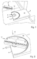
- Fig. 1 shows a plan view of a first base plate 3 of a component supply station.
- the base plate 3 has on a first side surface 10, a first receptacle 8 for a conveyor unit (in Fig. 1 not shown).
- the first receptacle 8 is circular and recessed into the first side surface 10.
- the first receptacle 8 is rotatably mounted about a (imaginary) first axis 15 which is perpendicular to the first side surface 10.
- the first base plate 3 has a second side surface 11, which is arranged perpendicular to the first side surface 10. In the second side surface, a pin 9 is sunk, which can fix the first receptacle 8 in a specific orientation relative to the first base plate 3.
- Fig. 2 shows an enlarged plan view of the component supply station 1 with a first base plate 3 accordingly Fig. 1 on which a conveyor unit 4 is arranged.
- the delivery unit 4 is clamped in the first receptacle 8 of the first side surface 10, so that upon rotation of the first receptacle 8, the delivery unit 4 is also rotated about the first axis 15.
- the first base plate 3 has notches 13, which indicate in which orientation the conveying unit is located relative to the first base plate 3.
- the conveyor unit 4 has a rail 12 which is arranged perpendicular to the first axis 15.
- the rail 12 has electric motors (not shown) adapted to convey a blister strip (not shown) such that the electrical components for a pick and place machine (shown in FIG Fig. 2 not shown) are available.
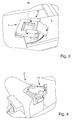
- Fig. 3 shows a plan view of a Bauteilbetikmodul 5.
- the Bauteilbetikmodul 5 comprises a second base plate 6, which features the first base plate (see Fig. 1 ) having.
- the component printing module 5 comprises a stencil holder 7 which rotates about a (imaginary) second axis 16 is arranged, which is perpendicular to the second base plate 6.
- Fig. 4 shows a perspective view of a placement machine 2 with a second receptacle 14, which can accommodate both the component supply station 1 and the Bauteilbedruckmodul 5.
- the first base plate 3 of the component supply station 1 or the second base plate 6 of the component printing module 5 are received in the second receptacle 14.
- the method according to the invention for equipping a printed circuit board with electrical components proceeds as follows. First, the first base plate 3 of the component supply station 1 and the second base plate 6 of the Bauteilbedruckmoduls 5 is infected in a predetermined orientation relative to the placement machine 2 to the placement machine 2. Subsequently, the conveyor unit 4 is rotated relative to the first axis 15 of the first base plate 3 until the components occupy a predetermined orientation relative to the loading machine 2 on the blister strip.
- the component printing module 5 is provided with solder and rotated relative to the second axis 16 until the component printing module 5 has the orientation of the components.
- the components are removed by means of the vacuum pipette from the component supply station 1 and placed in the component printing module 5 and applied with solder paste.
- the components are removed in the predetermined orientation by means of the vacuum pipette and placed in the predetermined orientation on the circuit board.
Landscapes
- Engineering & Computer Science (AREA)
- Manufacturing & Machinery (AREA)
- Microelectronics & Electronic Packaging (AREA)
- Electric Connection Of Electric Components To Printed Circuits (AREA)
- Supply And Installment Of Electrical Components (AREA)
Abstract
Description
- Die Erfindung bezieht sich auf eine Bauteilversorgungsstation, insbesondere ein Feeder für einen Bestückungsautomaten zum Bereitstellen von elektrischen Bauelementen für eine Leiterplatte und ein Verfahren zum Bestücken einer Leiterplatte mit elektrischen Bauelementen.
- Die Leiterplattenbestückung umfasst das Setzen und Löten von verschiedenen elektronischen Bauelementen auf eine leere, unbestückte Leiterplatte durch spezifische Setz- und Lötverfahren. Bei der Leiterplattenbestückung können prinzipiell zwei verschiedene Verfahren eingesetzt werden: die SMD-Bestückung (surface mounted device) und die THT-Bestückung (through hole technology).
- Die SMD-Bestückung erfolgt dabei meist vollautomatisch und kommt für alle kleinen Bauelemente, wie Widerstände, Kondensatoren und Mikrocontroller zum Einsatz, die meist in großer Anzahl bestückt werden. Die THT-Bestückung muss teilweise von Hand vorgenommen werden. Dies geschieht aus technischen Gründen und um Schäden an den bereits aufgelöteten Bauelementen zu vermeiden. Die THT-Bestückung kommt zumeist bei anzulötenden Leiterplattenverbindern, Steckerleisten und Kabeln zum Einsatz.
- Ein Bestückungsautomat ist eine Maschine, die in der Fertigung von Leiterplatten benutzt wird, um Bauelemente auf die Leiterplatte zu platzieren, die anschließend in einem Lötprozess verlötet werden. Die einzelnen Bauteile werden in einer Bauteilversorgungsstation (Feeder) dem Bestückungsautomaten zur Verfügung gestellt. SMD-Bauelemente werden in Form von Blistergurten auf Rollen (Tape & Reel) zur Verfügung gestellt.
- Ein Bestückungskopf, der in drei Achsen verfahrbar ist und um die Z-Achse rotieren kann, saugt in der Regel durch Unterdruck ein Bauteil aus dem Blistergurt und platziert das Bauteil auf der Leiterplatte. Sind alle Bauteile bestückt, wird die Leiterplatte über ein Fördersystem weitertransportiert und einem Reflowofen oder Wellenlötanlage zugeführt. Anschließend wird eine weitere leere Leiterplatte oder Leiterplattennutzen in die Bestückungsanlage zugeführt. Meist sind die Bestückungsautomaten modular ausgelegt, so dass man unterschiedliche Bauteilversorgungsstationen, Bestückungsköpfe usw. anbauen kann.
- Blistergurte sind Gurte, in denen die zu verarbeitenden Bauelemente verpackt sind. Der Blistergurt ist wie bei einer Filmrolle auf eine Rolle gewickelt. Ein Beispiel für solche Bauelemente sind Drahtstücke, die zum mechanischen und elektrischen Verbinden an einer Biegestelle einer biegbaren Leiterplatte angebracht werden. Solche Drahtstücke sind einzeln zwischen zwei Plastikstreifen eingepackt. Diese beiden Plastikstreifen mit den einzelnen Drahtstücken dazwischen bilden den Blistergurt.
- Die Bauteilversorgungsstation ist relativ zum Bestückungsautomaten dermaßen angeordnet, dass der Blistergurt die einzelnen Bauteile lediglich in einer einzigen vorbestimmten Orientierung relativ zum Bestückungskopf bereitstellt.
- Der Erfindung liegt die Aufgabe zugrunde, eine Bauteilversorgungsstation, welche die Bauteile in jeder beliebigen Orientierung relativ zum Bestückungskopf des Bestückungsautomaten bereitstellt, und ein Verfahren zum Bestücken einer Leiterplatte mit elektrischen Bauelementen bereitzustellen.
- Die Aufgabe wird erfindungsgemäß durch den Gegenstand der Erfindung gelöst. Der Gegenstand der Erfindung ist eine Bauteilversorgungsstation, insbesondere ein Feeder für einen Bestückungsautomaten zum Bereitstellen von elektrischen Bauelementen für eine Leiterplatte, umfassend eine erste Grundplatte zum Anstecken an den Bestückungsautomaten, so dass die erste Grundplatte eine vorbestimmte Orientierung relativ zum Bestückungsautomaten einnimmt, eine Fördereinheit zum Fördern eines Blistergurtes, an dem die Bauelemente angeordnet sind, wobei die Fördereinheit relativ zu einer zur ersten Grundplatte senkrechten ersten Achse drehbar gelagert ist, so dass die Bauelemente in der Ebene der ersten Grundplatte in einer vorbestimmten Orientierung relativ zur ersten Achse bereitstellbar sind.
- Dadurch, dass die Fördereinheit drehbar gelagert ist, lassen sich die Bauteile auf dem Blistergurt in jeder beliebigen Orientierung zur Grundplatte bereitstellen.
- Gemäß einer vorteilhaften Weiterbildung ist ein Bauteilbedruckmodul zum Bedrucken der Bauelemente mit Lot vorgesehen, wobei das Bauteilbedruckmodul relativ zu einer zur zweiten Grundplatte senkrechten zweiten Achse drehbar gelagert ist, und wobei die erste und zweite Achse parallel zueinander angeordnet sind, so dass das Bauteilbedruckmodul an der vorbestimmten Orientierungen der Bauelemente anpassbar ist.
- Gemäß einer vorteilhaften Variante weist das Bauteilbedruckmodul eine zweite Grundplatte zum Anstecken an den Bestückungsautomaten auf, so dass die zweite Grundplatte parallel zur ersten Grundplatte angeordnet ist, und wobei das Bauteilbedruckmodul einen Schablonenhalter aufweist, der auf der zweiten Grundplatte angeordnet ist und relativ zur zweiten Achse drehbar gelagert ist, so dass die Bauelemente in der vorbestimmten Orientierung in dem Schablonenhalter platzierbar sind.
- Gemäß einer günstigen Weiterbildung sind die erste und zweite Grundplatte als eine einzige Grundplatte ausgebildet, an der sowohl die Fördereinheit als auch das Bauteilbedruckmodul angeordnet ist.
- Die Aufgabe der Erfindung wird ebenfalls durch ein Verfahren gelöst. Das Verfahren beinhaltet ein Verfahren zum Bestücken einer Leiterplatte mit elektrischen Bauelementen, mittels einer Bauteilversorgungsstation, insbesondere eines Feeders für einen Bestückungsautomaten zum Bereitstellen von elektrischen Bauelementen für eine Leiterplatte, wobei die Bauteilversorgungsstation eine erste Grundplatte mit einer Fördereinheit zum Fördern eines Blistergurtes, an dem die Bauelemente angeordnet sind, aufweist,
umfassend die Verfahrensschritte: - Anstecken der ersten Grundplatte an den Bestückungsautomaten, so dass die erste Grundplatte eine vorbestimmte Orientierung relativ zum Bestückungsautomaten einnimmt,
- Drehen der Fördereinheit relativ zu einer senkrechten ersten Achse der Grundplatte, um die Bauelemente in der Ebene der ersten Grundplatte in einer vorbestimmten Orientierung relativ zur senkrechten ersten Achse bereitzustellen,
- Entnehmen des Bauelements in der vorbestimmten Orientierung mittels des Bestückungsautomaten, insbesondere einer Vakuumpipette des Bestückungsautomaten,
- Platzieren des Bauelements in der vorbestimmten Orientierung an der Leiterplatte.
- Gemäß einer vorteilhaften Variante ist ein Bauteilbedruckmodul zum Bedrucken der Bauelemente mit Lot vorgesehen, und wobei das Bauteilbedruckmodul relativ zu einer zu einer zweiten Grundplatte senkrechten zweiten Achse gedreht wird, um das Bauteilbedruckmodul an die vorbestimmte Orientierung der Bauelemente anzupassen, und wobei die Bauelemente nach dem Entnehmen mittels der Vakuumpipette und vor dem Platzieren an der Leiterplatte an dem Bauteilbedruckmodul platziert werden, um mit Lotpaste beaufschlagt zu werden.
- Die Erfindung wird anhand der nachfolgenden Zeichnungen näher erläutert. Es zeigt:
-
Fig. 1 : eine Draufsicht auf eine erste Grundplatte einer Bauteilversorgungsstation, -
Fig. 2 : eine Draufsicht einer Bauteilversorgungsstation mit einer Fördereinheit und einer ersten Grundplatte entsprechendFig. 1 , -
Fig. 3 : eine Draufsicht auf ein Bauteilbedruckmodul, und -
Fig. 4 : eine perspektivische Ansicht eines Bestückungsautomaten. -
Fig. 1 zeigt eine Draufsicht auf eine erste Grundplatte 3 einer Bauteilversorgungsstation. Die Grundplatte 3 weist auf einer ersten Seitenfläche 10 eine erste Aufnahme 8 für eine Fördereinheit (inFig. 1 nicht dargestellt) auf. Die erste Aufnahme 8 ist kreisförmig ausgestaltet und in die erste Seitenfläche 10 versenkt. Des Weiteren ist die erste Aufnahme 8 drehbar um eine (gedachte) erste Achse 15 gelagert, die senkrecht auf die erste Seitenfläche 10 steht. Die erste Grundplatte 3 weist eine zweite Seitenfläche 11 auf, die senkrecht zur ersten Seitenfläche 10 angeordnet ist. In die zweite Seitenfläche ist ein Stift 9 versenkt, welcher die erste Aufnahme 8 in einer bestimmten Orientierung relativ zu der ersten Grundplatte 3 festsetzen kann. -
Fig. 2 zeigt eine vergrößerte Draufsicht auf die Bauteilversorgungsstation 1 mit einer ersten Grundplatte 3 entsprechendFig. 1 , auf die eine Fördereinheit 4 angeordnet ist. Die Fördereinheit 4 ist in der ersten Aufnahme 8 der ersten Seitenfläche 10 eingespannt, so dass bei einem Drehen der ersten Aufnahme 8 die Fördereinheit 4 ebenfalls um die erste Achse 15 mitgedreht wird. Ferner weist die erste Grundplatte 3 Einkerbungen 13 auf, die anzeigen, in welcher Orientierung sich die Fördereinheit relativ zur ersten Grundplatte 3 befindet. Die Fördereinheit 4 weist eine Schiene 12 auf, die senkrecht zur ersten Achse 15 angeordnet ist. Die Schiene 12 weist Elektromotoren (nicht dargestellt) auf, die geeignet sind, um einen Blistergurt (nicht dargestellt) zu fördern, so dass die an dem Blistergurt befestigten elektrischen Bauelemente für einen Bestückungsautomaten (inFig. 2 nicht dargestellt) bereitstellbar sind. -
Fig. 3 zeigt eine Draufsicht auf ein Bauteilbedruckmodul 5. Das Bauteilbedruckmodul 5 umfasst eine zweite Grundplatte 6, welche die Merkmale der ersten Grundplatte (sieheFig. 1 ) aufweist. Ferner umfasst das Bauteilbedruckmodul 5 einen Schablonenhalter 7, welcher drehbar um eine (gedachte) zweite Achse 16 angeordnet ist, die senkrecht zur zweiten Grundplatte 6 steht. -
Fig. 4 zeigt eine perspektivische Ansicht eines Bestückungsautomaten 2 mit einer zweiten Aufnahme 14, welche sowohl die Bauteilversorgungsstation 1 als auch das Bauteilbedruckmodul 5 aufnehmen kann. Es werden jeweils die erste Grundplatte 3 der Bauteilversorgungsstation 1 oder die zweite Grundplatte 6 des Bauteilbedruckmoduls 5 in die zweite Aufnahme 14 aufgenommen. - Das erfindungsgemäße Verfahren zum Bestücken einer Leiterplatte mit elektrischen Bauelementen läuft folgendermaßen ab. Zunächst wird die erste Grundplatte 3 der Bauteilversorgungsstation 1 und die zweite Grundplatte 6 des Bauteilbedruckmoduls 5 in einer vorbestimmten Orientierung relativ zum Bestückungsautomaten 2 an den Bestückungsautomaten 2 angesteckt. Anschließend wird die Fördereinheit 4 relativ zu der ersten Achse 15 der ersten Grundplatte 3 gedreht bis die Bauelemente auf dem Blistergurt eine vorbestimmte Orientierung relativ zum Bestückungsautomaten 2 einnehmen.
- Anschließend wird das Bauteilbedruckmodul 5 mit Lot versehen und relativ zu der zweiten Achse 16 gedreht, bis das Bauteilbedruckmodul 5 die Orientierung der Bauelemente aufweist. Die Bauelemente werden mittels der Vakuumpipette von der Bauteilversorgungsstation 1 entnommen und in dem Bauteilbedruckmodul 5 platziert und mit Lotpaste beaufschlagt. Anschließend werden die Bauelemente in der vorbestimmten Orientierung mittels der Vakuumpipette entnommen und in der vorbestimmten Orientierung an der Leiterplatte platziert.
-
- 1
- Bauteilversorgungsstation
- 2
- Bestückungsautomat
- 3
- Erste Grundplatte
- 4
- Fördereinheit
- 5
- Bauteilbedruckmodul
- 6
- Zweite Grundplatte
- 7
- Schablonenhalter
- 8
- Erste Aufnahme
- 9
- Stift
- 10
- Erste Seitenfläche
- 11
- Zweite Seitenfläche
- 12
- Schiene
- 13
- Einkerbungen
- 14
- Zweite Aufnahme
- 15
- Erste Achse
- 16
- Zweite Achse
Claims (6)
- Bauteilversorgungsstation, insbesondere ein Feeder für einen Bestückungsautomaten (2) zum Bereitstellen von elektrischen Bauelementen für eine Leiterplatte, umfassend
eine erste Grundplatte (3) zum Anstecken an den Bestückungsautomaten (2), so dass die erste Grundplatte (3) eine vorbestimmte Orientierung relativ zum Bestückungsautomaten (2) einnimmt,
eine Fördereinheit (4) zum Fördern eines Blistergurtes, an dem die Bauelemente angeordnet sind,
wobei die Fördereinheit (4) relativ zu einer zur ersten Grundplatte (3) senkrechten ersten Achse (15) drehbar gelagert ist, so dass die Bauelemente in der Ebene der ersten Grundplatte (3) in einer vorbestimmten Orientierung relativ zur senkrechten ersten Achse (15) bereitstellbar sind. - Bauteilversorgungsstation nach Anspruch 1, wobei ein Bauteilbedruckmodul (5) zum Bedrucken der Bauelemente mit Lot vorgesehen ist, wobei das Bauteilbedruckmodul (5) relativ zu einer zur ersten Grundplatte (3) senkrechten zweiten Achse (16) drehbar gelagert ist, und wobei die erste und zweite senkrechte Achse (16) parallel zueinander angeordnet sind, so dass das Bauteilbedruckmodul (5) an der vorbestimmten Orientierungen der Bauelemente anpassbar ist.
- Bauteilversorgungsstation nach Anspruch 2, wobei das Bauteilbedruckmodul (5) eine zweite Grundplatte (6) zum Anstecken an den Bestückungsautomaten (2) aufweist, so dass die zweite Grundplatte (6) parallel zur ersten Grundplatte (3) angeordnet ist, und wobei das Bauteilbedruckmodul (5) einen Schablonenhalter (7) aufweist, der auf der zweiten Grundplatte (6) angeordnet ist und relativ zur zweiten senkrechten Achse (16) drehbar gelagert ist, so dass die Bauelemente in der vorbestimmten Orientierungen in dem Schablonenhalter (7) platzierbar sind.
- Bauteilversorgungsstation nach Anspruch 2 oder 3, wobei die erste und zweite Grundplatte (3, 6) als eine einzige Grundplatte ausgebildet sind, an dem sowohl die Fördereinheit (4) als auch das Bauteilbedruckmodul (5) angeordnet ist.
- Verfahren zum Bestücken einer Leiterplatte mit elektrischen Bauelementen, mittels einer Bauteilversorgungsstation (1), insbesondere eines Feeders für einen Bestückungsautomaten (2) zum Bereitstellen von elektrischen Bauelementen für eine Leiterplatte, wobei die Bauteilversorgungsstation (1) eine erste Grundplatte (3) mit einer Fördereinheit (4) zum Fördern eines Blistergurtes, an dem die Bauelemente angeordnet sind, aufweist,
umfassend die Verfahrensschritte,
Anstecken der ersten Grundplatte (3) an den Bestückungsautomaten, so dass die erste Grundplatte (3) eine vorbestimmte Orientierung relativ zum Bestückungsautomaten (2) einnimmt,
Drehen der Fördereinheit (4) relativ zu einer senkrechten ersten Achse (15) der ersten Grundplatte (3), um die Bauelemente in der Ebene der ersten Grundplatte (3) in einer vorbestimmten Orientierung relativ zur senkrechten ersten Achse (15) bereitzustellen,
Entnehmen des Bauelements in der vorbestimmten Orientierung mittels einer Vakuumpipette,
Platzieren des Bauelements in der vorbestimmten Orientierung an der Leiterplatte. - Verfahren nach Anspruch 5, wobei ein Bauteilbedruckmodul (5) zum Bedrucken der Bauelemente mit Lot vorgesehen ist, und wobei das Bauteilbedruckmodul (5) relativ zu einer zu einer zweiten Grundplatte (6) senkrechten zweiten Achse (16) gedreht wird, um das Bauteilbedruckmodul (5) an die vorbestimmte Orientierung der Bauelemente anzupassen, und wobei die Bauelemente nach dem Entnehmen mittels der Vakuumpipette und vor dem Platzieren an der Leiterplatte an dem Bauteilbedruckmodul (5) platziert werden, um mit Lotpaste beaufschlagt zu werden.
Applications Claiming Priority (1)
| Application Number | Priority Date | Filing Date | Title |
|---|---|---|---|
| DE102014118610.9A DE102014118610A1 (de) | 2014-12-15 | 2014-12-15 | Bauteilversorgungsstation für einen Bestückungsautomaten |
Publications (2)
| Publication Number | Publication Date |
|---|---|
| EP3035784A1 true EP3035784A1 (de) | 2016-06-22 |
| EP3035784B1 EP3035784B1 (de) | 2018-11-14 |
Family
ID=54754496
Family Applications (1)
| Application Number | Title | Priority Date | Filing Date |
|---|---|---|---|
| EP15196926.8A Active EP3035784B1 (de) | 2014-12-15 | 2015-11-30 | Bauteilversorgungsstation für einen bestückungsautomaten |
Country Status (3)
| Country | Link |
|---|---|
| EP (1) | EP3035784B1 (de) |
| CN (1) | CN105704997B (de) |
| DE (1) | DE102014118610A1 (de) |
Families Citing this family (1)
| Publication number | Priority date | Publication date | Assignee | Title |
|---|---|---|---|---|
| DE102020132260B4 (de) | 2020-12-04 | 2022-06-15 | Endress+Hauser SE+Co. KG | Komponentenbereitstellstation und Verfahren zum Fördern eines Blistergurts in einer Komponentenbereitstellstation |
Citations (3)
| Publication number | Priority date | Publication date | Assignee | Title |
|---|---|---|---|---|
| GB2183820A (en) * | 1985-11-09 | 1987-06-10 | Dynapert Precima Ltd | Electronic component placement |
| EP0860102A1 (de) * | 1995-11-06 | 1998-08-26 | Matsushita Electric Industrial Co., Ltd. | Einrichtung zur montage von bauteilen |
| WO2014118994A1 (ja) * | 2013-02-04 | 2014-08-07 | 富士機械製造株式会社 | カセット式テープフィーダ及び部品実装機 |
Family Cites Families (2)
| Publication number | Priority date | Publication date | Assignee | Title |
|---|---|---|---|---|
| SE517579C2 (sv) * | 1999-03-10 | 2002-06-25 | Foerpackningsinnovation Norden | Matarenhet för frammatning av ett förpackningsmedium |
| JP5845409B2 (ja) * | 2011-11-08 | 2016-01-20 | パナソニックIpマネジメント株式会社 | 部品実装装置 |
-
2014
- 2014-12-15 DE DE102014118610.9A patent/DE102014118610A1/de not_active Withdrawn
-
2015
- 2015-11-30 EP EP15196926.8A patent/EP3035784B1/de active Active
- 2015-12-15 CN CN201510931654.0A patent/CN105704997B/zh active Active
Patent Citations (3)
| Publication number | Priority date | Publication date | Assignee | Title |
|---|---|---|---|---|
| GB2183820A (en) * | 1985-11-09 | 1987-06-10 | Dynapert Precima Ltd | Electronic component placement |
| EP0860102A1 (de) * | 1995-11-06 | 1998-08-26 | Matsushita Electric Industrial Co., Ltd. | Einrichtung zur montage von bauteilen |
| WO2014118994A1 (ja) * | 2013-02-04 | 2014-08-07 | 富士機械製造株式会社 | カセット式テープフィーダ及び部品実装機 |
Also Published As
| Publication number | Publication date |
|---|---|
| CN105704997A (zh) | 2016-06-22 |
| DE102014118610A1 (de) | 2016-07-21 |
| CN105704997B (zh) | 2018-12-04 |
| EP3035784B1 (de) | 2018-11-14 |
Similar Documents
| Publication | Publication Date | Title |
|---|---|---|
| DE2949196A1 (de) | Aufnahmevorrichtung fuer elektronische bauelemente in chip-form und verfahren zur serienweisen bereitstellung solcher bauelemente fuer fertigungsprozesse o.dgl. | |
| EP0315799A1 (de) | Vorrichtung und Verfahren zum Bestücken von Leiterplatten mit Bauelementen | |
| DE1064127B (de) | Verfahren zur Bestueckung von sogenannten gedruckten Schaltungen mit Schaltungselementen | |
| EP3035784B1 (de) | Bauteilversorgungsstation für einen bestückungsautomaten | |
| EP0951205B1 (de) | Verfahren zum automatischen Bestücken der Ober- und Unterseite von Leiterplatten mit SMD-Bauteilen | |
| DE102012107162A1 (de) | Abziehvorrichtung zum Abziehen einer Deckfolie von einem Bauelementegurt sowie Zuführvorrichtung zur Zuführung von Bauelementegurten zu einem Bestückautomaten | |
| EP1114576B1 (de) | Vorrichtung zum bestücken von schaltungsträgern | |
| DE112022007107T5 (de) | Zusammenstellungsvorrichtung-Extraktionssystem | |
| EP0224747B1 (de) | Verfahren und Vorrichtung zur Bestückung von Substraten mit Mikropacks | |
| DE202015106225U1 (de) | Vorrichtung zum automatisierten Abtrennen, Vereinzeln und Sortieren von bestückten und unbestückten Leiterplatten | |
| DE102013113389A1 (de) | Bauteilversorgungsstation für einen Bestückungsautomaten | |
| DE112022007175T5 (de) | Bauteilbestätigungsvorrichtung | |
| DE102020132260B4 (de) | Komponentenbereitstellstation und Verfahren zum Fördern eines Blistergurts in einer Komponentenbereitstellstation | |
| DE10021078A1 (de) | Flächenmontagevorrichtung und Verfahren für die Flächenbestückung | |
| DE69902882T2 (de) | Bauteilbestückungsautomat | |
| DE112021008455T5 (de) | Maschine zur Montage von Komponenten und Verfahren zur Herstellung von Substraten | |
| DE112021006890T5 (de) | Zuleitungseinrichtungs-einsetzung/entnahme-vorrichtung, sowie bauteilmontagesystem | |
| DE2747895C2 (de) | Vorrichtung und Verfahren zum Entlöten | |
| DE112022006264T5 (de) | Vorrichtung zum unterstützen von bauelementvorbereitung, vorrichtung zum unterstützen von lötpastenvorbereitung, verfahren zum unterstützen von bauelementvorbereitung, verfahren zum unterstützen von lötpastenvorbereitung, programm zum unterstützen von bauelementvorbereitung, programm zum unterstützen von lötpastenvorbereitung und datenträger | |
| DE10230901B4 (de) | Vorrichtung zum Bestücken von Substraten mit Bauelementen mittels eines Bestückkopfes | |
| DE2930089C2 (de) | Vorrichtung zum Einsetzen von Bauelementen in Öffnungen von gedruckten Schaltungsplatten | |
| DE112023006391T5 (de) | Bauteilverwaltungs-Vorrichtung undBauteilverwaltungs-Verfahren | |
| DE112022007963T5 (de) | Bauteilmontagesystem | |
| EP4520145A1 (de) | Verfahren zum automatischen nachladen von smd-bauelemente-rollen an smd-bestückungsautomaten | |
| DE112022007430T5 (de) | Prüfbildanzeigesystem und Prüfbildanzeigeverfahren |
Legal Events
| Date | Code | Title | Description |
|---|---|---|---|
| PUAI | Public reference made under article 153(3) epc to a published international application that has entered the european phase |
Free format text: ORIGINAL CODE: 0009012 |
|
| AK | Designated contracting states |
Kind code of ref document: A1 Designated state(s): AL AT BE BG CH CY CZ DE DK EE ES FI FR GB GR HR HU IE IS IT LI LT LU LV MC MK MT NL NO PL PT RO RS SE SI SK SM TR |
|
| AX | Request for extension of the european patent |
Extension state: BA ME |
|
| 17P | Request for examination filed |
Effective date: 20160725 |
|
| RBV | Designated contracting states (corrected) |
Designated state(s): AL AT BE BG CH CY CZ DE DK EE ES FI FR GB GR HR HU IE IS IT LI LT LU LV MC MK MT NL NO PL PT RO RS SE SI SK SM TR |
|
| RAP1 | Party data changed (applicant data changed or rights of an application transferred) |
Owner name: ENDRESS+HAUSER SE+CO. KG |
|
| GRAP | Despatch of communication of intention to grant a patent |
Free format text: ORIGINAL CODE: EPIDOSNIGR1 |
|
| INTG | Intention to grant announced |
Effective date: 20180711 |
|
| GRAS | Grant fee paid |
Free format text: ORIGINAL CODE: EPIDOSNIGR3 |
|
| GRAA | (expected) grant |
Free format text: ORIGINAL CODE: 0009210 |
|
| AK | Designated contracting states |
Kind code of ref document: B1 Designated state(s): AL AT BE BG CH CY CZ DE DK EE ES FI FR GB GR HR HU IE IS IT LI LT LU LV MC MK MT NL NO PL PT RO RS SE SI SK SM TR |
|
| REG | Reference to a national code |
Ref country code: CH Ref legal event code: EP Ref country code: AT Ref legal event code: REF Ref document number: 1066401 Country of ref document: AT Kind code of ref document: T Effective date: 20181115 |
|
| REG | Reference to a national code |
Ref country code: DE Ref legal event code: R096 Ref document number: 502015006851 Country of ref document: DE |
|
| REG | Reference to a national code |
Ref country code: IE Ref legal event code: FG4D Free format text: LANGUAGE OF EP DOCUMENT: GERMAN |
|
| REG | Reference to a national code |
Ref country code: CH Ref legal event code: NV Representative=s name: DENNEMEYER AG, CH |
|
| REG | Reference to a national code |
Ref country code: NL Ref legal event code: MP Effective date: 20181114 |
|
| REG | Reference to a national code |
Ref country code: LT Ref legal event code: MG4D |
|
| PG25 | Lapsed in a contracting state [announced via postgrant information from national office to epo] |
Ref country code: HR Free format text: LAPSE BECAUSE OF FAILURE TO SUBMIT A TRANSLATION OF THE DESCRIPTION OR TO PAY THE FEE WITHIN THE PRESCRIBED TIME-LIMIT Effective date: 20181114 Ref country code: NO Free format text: LAPSE BECAUSE OF FAILURE TO SUBMIT A TRANSLATION OF THE DESCRIPTION OR TO PAY THE FEE WITHIN THE PRESCRIBED TIME-LIMIT Effective date: 20190214 Ref country code: LV Free format text: LAPSE BECAUSE OF FAILURE TO SUBMIT A TRANSLATION OF THE DESCRIPTION OR TO PAY THE FEE WITHIN THE PRESCRIBED TIME-LIMIT Effective date: 20181114 Ref country code: FI Free format text: LAPSE BECAUSE OF FAILURE TO SUBMIT A TRANSLATION OF THE DESCRIPTION OR TO PAY THE FEE WITHIN THE PRESCRIBED TIME-LIMIT Effective date: 20181114 Ref country code: BG Free format text: LAPSE BECAUSE OF FAILURE TO SUBMIT A TRANSLATION OF THE DESCRIPTION OR TO PAY THE FEE WITHIN THE PRESCRIBED TIME-LIMIT Effective date: 20190214 Ref country code: IS Free format text: LAPSE BECAUSE OF FAILURE TO SUBMIT A TRANSLATION OF THE DESCRIPTION OR TO PAY THE FEE WITHIN THE PRESCRIBED TIME-LIMIT Effective date: 20190314 Ref country code: LT Free format text: LAPSE BECAUSE OF FAILURE TO SUBMIT A TRANSLATION OF THE DESCRIPTION OR TO PAY THE FEE WITHIN THE PRESCRIBED TIME-LIMIT Effective date: 20181114 Ref country code: ES Free format text: LAPSE BECAUSE OF FAILURE TO SUBMIT A TRANSLATION OF THE DESCRIPTION OR TO PAY THE FEE WITHIN THE PRESCRIBED TIME-LIMIT Effective date: 20181114 |
|
| PG25 | Lapsed in a contracting state [announced via postgrant information from national office to epo] |
Ref country code: GR Free format text: LAPSE BECAUSE OF FAILURE TO SUBMIT A TRANSLATION OF THE DESCRIPTION OR TO PAY THE FEE WITHIN THE PRESCRIBED TIME-LIMIT Effective date: 20190215 Ref country code: NL Free format text: LAPSE BECAUSE OF FAILURE TO SUBMIT A TRANSLATION OF THE DESCRIPTION OR TO PAY THE FEE WITHIN THE PRESCRIBED TIME-LIMIT Effective date: 20181114 Ref country code: PT Free format text: LAPSE BECAUSE OF FAILURE TO SUBMIT A TRANSLATION OF THE DESCRIPTION OR TO PAY THE FEE WITHIN THE PRESCRIBED TIME-LIMIT Effective date: 20190314 Ref country code: AL Free format text: LAPSE BECAUSE OF FAILURE TO SUBMIT A TRANSLATION OF THE DESCRIPTION OR TO PAY THE FEE WITHIN THE PRESCRIBED TIME-LIMIT Effective date: 20181114 Ref country code: SE Free format text: LAPSE BECAUSE OF FAILURE TO SUBMIT A TRANSLATION OF THE DESCRIPTION OR TO PAY THE FEE WITHIN THE PRESCRIBED TIME-LIMIT Effective date: 20181114 Ref country code: RS Free format text: LAPSE BECAUSE OF FAILURE TO SUBMIT A TRANSLATION OF THE DESCRIPTION OR TO PAY THE FEE WITHIN THE PRESCRIBED TIME-LIMIT Effective date: 20181114 |
|
| PG25 | Lapsed in a contracting state [announced via postgrant information from national office to epo] |
Ref country code: PL Free format text: LAPSE BECAUSE OF FAILURE TO SUBMIT A TRANSLATION OF THE DESCRIPTION OR TO PAY THE FEE WITHIN THE PRESCRIBED TIME-LIMIT Effective date: 20181114 Ref country code: CZ Free format text: LAPSE BECAUSE OF FAILURE TO SUBMIT A TRANSLATION OF THE DESCRIPTION OR TO PAY THE FEE WITHIN THE PRESCRIBED TIME-LIMIT Effective date: 20181114 Ref country code: IT Free format text: LAPSE BECAUSE OF FAILURE TO SUBMIT A TRANSLATION OF THE DESCRIPTION OR TO PAY THE FEE WITHIN THE PRESCRIBED TIME-LIMIT Effective date: 20181114 Ref country code: LU Free format text: LAPSE BECAUSE OF NON-PAYMENT OF DUE FEES Effective date: 20181130 Ref country code: DK Free format text: LAPSE BECAUSE OF FAILURE TO SUBMIT A TRANSLATION OF THE DESCRIPTION OR TO PAY THE FEE WITHIN THE PRESCRIBED TIME-LIMIT Effective date: 20181114 |
|
| REG | Reference to a national code |
Ref country code: DE Ref legal event code: R097 Ref document number: 502015006851 Country of ref document: DE |
|
| REG | Reference to a national code |
Ref country code: BE Ref legal event code: MM Effective date: 20181130 |
|
| REG | Reference to a national code |
Ref country code: IE Ref legal event code: MM4A |
|
| PG25 | Lapsed in a contracting state [announced via postgrant information from national office to epo] |
Ref country code: RO Free format text: LAPSE BECAUSE OF FAILURE TO SUBMIT A TRANSLATION OF THE DESCRIPTION OR TO PAY THE FEE WITHIN THE PRESCRIBED TIME-LIMIT Effective date: 20181114 Ref country code: MC Free format text: LAPSE BECAUSE OF FAILURE TO SUBMIT A TRANSLATION OF THE DESCRIPTION OR TO PAY THE FEE WITHIN THE PRESCRIBED TIME-LIMIT Effective date: 20181114 Ref country code: SK Free format text: LAPSE BECAUSE OF FAILURE TO SUBMIT A TRANSLATION OF THE DESCRIPTION OR TO PAY THE FEE WITHIN THE PRESCRIBED TIME-LIMIT Effective date: 20181114 Ref country code: EE Free format text: LAPSE BECAUSE OF FAILURE TO SUBMIT A TRANSLATION OF THE DESCRIPTION OR TO PAY THE FEE WITHIN THE PRESCRIBED TIME-LIMIT Effective date: 20181114 Ref country code: SM Free format text: LAPSE BECAUSE OF FAILURE TO SUBMIT A TRANSLATION OF THE DESCRIPTION OR TO PAY THE FEE WITHIN THE PRESCRIBED TIME-LIMIT Effective date: 20181114 |
|
| PLBE | No opposition filed within time limit |
Free format text: ORIGINAL CODE: 0009261 |
|
| STAA | Information on the status of an ep patent application or granted ep patent |
Free format text: STATUS: NO OPPOSITION FILED WITHIN TIME LIMIT |
|
| 26N | No opposition filed |
Effective date: 20190815 |
|
| PG25 | Lapsed in a contracting state [announced via postgrant information from national office to epo] |
Ref country code: SI Free format text: LAPSE BECAUSE OF FAILURE TO SUBMIT A TRANSLATION OF THE DESCRIPTION OR TO PAY THE FEE WITHIN THE PRESCRIBED TIME-LIMIT Effective date: 20181114 Ref country code: IE Free format text: LAPSE BECAUSE OF NON-PAYMENT OF DUE FEES Effective date: 20181130 Ref country code: FR Free format text: LAPSE BECAUSE OF NON-PAYMENT OF DUE FEES Effective date: 20190114 |
|
| PG25 | Lapsed in a contracting state [announced via postgrant information from national office to epo] |
Ref country code: BE Free format text: LAPSE BECAUSE OF NON-PAYMENT OF DUE FEES Effective date: 20181130 |
|
| PG25 | Lapsed in a contracting state [announced via postgrant information from national office to epo] |
Ref country code: MT Free format text: LAPSE BECAUSE OF FAILURE TO SUBMIT A TRANSLATION OF THE DESCRIPTION OR TO PAY THE FEE WITHIN THE PRESCRIBED TIME-LIMIT Effective date: 20181114 |
|
| PG25 | Lapsed in a contracting state [announced via postgrant information from national office to epo] |
Ref country code: TR Free format text: LAPSE BECAUSE OF FAILURE TO SUBMIT A TRANSLATION OF THE DESCRIPTION OR TO PAY THE FEE WITHIN THE PRESCRIBED TIME-LIMIT Effective date: 20181114 |
|
| PG25 | Lapsed in a contracting state [announced via postgrant information from national office to epo] |
Ref country code: MK Free format text: LAPSE BECAUSE OF NON-PAYMENT OF DUE FEES Effective date: 20181114 Ref country code: CY Free format text: LAPSE BECAUSE OF FAILURE TO SUBMIT A TRANSLATION OF THE DESCRIPTION OR TO PAY THE FEE WITHIN THE PRESCRIBED TIME-LIMIT Effective date: 20181114 Ref country code: HU Free format text: LAPSE BECAUSE OF FAILURE TO SUBMIT A TRANSLATION OF THE DESCRIPTION OR TO PAY THE FEE WITHIN THE PRESCRIBED TIME-LIMIT; INVALID AB INITIO Effective date: 20151130 |
|
| GBPC | Gb: european patent ceased through non-payment of renewal fee |
Effective date: 20191130 |
|
| PG25 | Lapsed in a contracting state [announced via postgrant information from national office to epo] |
Ref country code: GB Free format text: LAPSE BECAUSE OF NON-PAYMENT OF DUE FEES Effective date: 20191130 |
|
| P01 | Opt-out of the competence of the unified patent court (upc) registered |
Effective date: 20230601 |
|
| REG | Reference to a national code |
Ref country code: CH Ref legal event code: U11 Free format text: ST27 STATUS EVENT CODE: U-0-0-U10-U11 (AS PROVIDED BY THE NATIONAL OFFICE) Effective date: 20251201 |
|
| PGFP | Annual fee paid to national office [announced via postgrant information from national office to epo] |
Ref country code: DE Payment date: 20251119 Year of fee payment: 11 |
|
| PGFP | Annual fee paid to national office [announced via postgrant information from national office to epo] |
Ref country code: AT Payment date: 20251120 Year of fee payment: 11 |
|
| PGFP | Annual fee paid to national office [announced via postgrant information from national office to epo] |
Ref country code: CH Payment date: 20251201 Year of fee payment: 11 |