EP3035433A1 - Lead-acid battery - Google Patents
Lead-acid battery Download PDFInfo
- Publication number
- EP3035433A1 EP3035433A1 EP15197187.6A EP15197187A EP3035433A1 EP 3035433 A1 EP3035433 A1 EP 3035433A1 EP 15197187 A EP15197187 A EP 15197187A EP 3035433 A1 EP3035433 A1 EP 3035433A1
- Authority
- EP
- European Patent Office
- Prior art keywords
- negative electrode
- concentration
- lead
- electrolyte solution
- mass
- Prior art date
- Legal status (The legal status is an assumption and is not a legal conclusion. Google has not performed a legal analysis and makes no representation as to the accuracy of the status listed.)
- Granted
Links
Images




Classifications
-
- H—ELECTRICITY
- H01—ELECTRIC ELEMENTS
- H01M—PROCESSES OR MEANS, e.g. BATTERIES, FOR THE DIRECT CONVERSION OF CHEMICAL ENERGY INTO ELECTRICAL ENERGY
- H01M4/00—Electrodes
- H01M4/02—Electrodes composed of, or comprising, active material
- H01M4/14—Electrodes for lead-acid accumulators
-
- H—ELECTRICITY
- H01—ELECTRIC ELEMENTS
- H01M—PROCESSES OR MEANS, e.g. BATTERIES, FOR THE DIRECT CONVERSION OF CHEMICAL ENERGY INTO ELECTRICAL ENERGY
- H01M10/00—Secondary cells; Manufacture thereof
- H01M10/06—Lead-acid accumulators
- H01M10/08—Selection of materials as electrolytes
-
- H—ELECTRICITY
- H01—ELECTRIC ELEMENTS
- H01M—PROCESSES OR MEANS, e.g. BATTERIES, FOR THE DIRECT CONVERSION OF CHEMICAL ENERGY INTO ELECTRICAL ENERGY
- H01M10/00—Secondary cells; Manufacture thereof
- H01M10/06—Lead-acid accumulators
-
- H—ELECTRICITY
- H01—ELECTRIC ELEMENTS
- H01M—PROCESSES OR MEANS, e.g. BATTERIES, FOR THE DIRECT CONVERSION OF CHEMICAL ENERGY INTO ELECTRICAL ENERGY
- H01M4/00—Electrodes
- H01M4/02—Electrodes composed of, or comprising, active material
- H01M4/36—Selection of substances as active materials, active masses, active liquids
- H01M4/58—Selection of substances as active materials, active masses, active liquids of inorganic compounds other than oxides or hydroxides, e.g. sulfides, selenides, tellurides, halogenides or LiCoFy; of polyanionic structures, e.g. phosphates, silicates or borates
- H01M4/583—Carbonaceous material, e.g. graphite-intercalation compounds or CFx
-
- H—ELECTRICITY
- H01—ELECTRIC ELEMENTS
- H01M—PROCESSES OR MEANS, e.g. BATTERIES, FOR THE DIRECT CONVERSION OF CHEMICAL ENERGY INTO ELECTRICAL ENERGY
- H01M50/00—Constructional details or processes of manufacture of the non-active parts of electrochemical cells other than fuel cells, e.g. hybrid cells
- H01M50/10—Primary casings; Jackets or wrappings
-
- H—ELECTRICITY
- H01—ELECTRIC ELEMENTS
- H01M—PROCESSES OR MEANS, e.g. BATTERIES, FOR THE DIRECT CONVERSION OF CHEMICAL ENERGY INTO ELECTRICAL ENERGY
- H01M10/00—Secondary cells; Manufacture thereof
- H01M10/06—Lead-acid accumulators
- H01M10/08—Selection of materials as electrolytes
- H01M10/10—Immobilising of electrolyte
-
- H—ELECTRICITY
- H01—ELECTRIC ELEMENTS
- H01M—PROCESSES OR MEANS, e.g. BATTERIES, FOR THE DIRECT CONVERSION OF CHEMICAL ENERGY INTO ELECTRICAL ENERGY
- H01M2220/00—Batteries for particular applications
- H01M2220/20—Batteries in motive systems, e.g. vehicle, ship, plane
-
- Y—GENERAL TAGGING OF NEW TECHNOLOGICAL DEVELOPMENTS; GENERAL TAGGING OF CROSS-SECTIONAL TECHNOLOGIES SPANNING OVER SEVERAL SECTIONS OF THE IPC; TECHNICAL SUBJECTS COVERED BY FORMER USPC CROSS-REFERENCE ART COLLECTIONS [XRACs] AND DIGESTS
- Y02—TECHNOLOGIES OR APPLICATIONS FOR MITIGATION OR ADAPTATION AGAINST CLIMATE CHANGE
- Y02E—REDUCTION OF GREENHOUSE GAS [GHG] EMISSIONS, RELATED TO ENERGY GENERATION, TRANSMISSION OR DISTRIBUTION
- Y02E60/00—Enabling technologies; Technologies with a potential or indirect contribution to GHG emissions mitigation
- Y02E60/10—Energy storage using batteries
-
- Y—GENERAL TAGGING OF NEW TECHNOLOGICAL DEVELOPMENTS; GENERAL TAGGING OF CROSS-SECTIONAL TECHNOLOGIES SPANNING OVER SEVERAL SECTIONS OF THE IPC; TECHNICAL SUBJECTS COVERED BY FORMER USPC CROSS-REFERENCE ART COLLECTIONS [XRACs] AND DIGESTS
- Y02—TECHNOLOGIES OR APPLICATIONS FOR MITIGATION OR ADAPTATION AGAINST CLIMATE CHANGE
- Y02P—CLIMATE CHANGE MITIGATION TECHNOLOGIES IN THE PRODUCTION OR PROCESSING OF GOODS
- Y02P70/00—Climate change mitigation technologies in the production process for final industrial or consumer products
- Y02P70/50—Manufacturing or production processes characterised by the final manufactured product
Definitions
- the present invention relates to a lead-acid battery.
- JP-A-2012-142185 discusses improving the life performance of a lead-acid battery in an idling-stop mode at both normal and high temperatures. For this purpose, it proposes that: a Pb-Sn-Sb alloy layer is provided on the surface of a negative electrode grid; Li and A1 are contained in electrolyte solution; and Na concentration of the electrolyte solution is set to be 0.04 mol/L or less.
- the volume of an element of a sealed type lead-acid battery is defined by the height of electrode plates x the width of the electrode plates x the thickness of the element. It is disclosed that when the mass of a negative active material per unit volume of the element is 0.84 g/cm 3 or more and 1.20 g/cm 3 or less, the high-rate discharge performance improves. However, the influences of the Ba sulfate concentration and the Na concentration have not been examined.
- JP-A-2003-178806 discusses the influences of the mass of the positive active material and the mass of the negative active material in a valve-regulated lead-acid battery, and shows an example in which the density of the positive active material is 4.20 g/cm 3 , and the mass ratio between the positive active material and the negative active material is 1.2.
- a lead-acid battery In a mode like an idling-stop mode, a lead-acid battery is not sufficiently charged, and thus the crystallization of lead sulfate is likely to proceed in the negative active material. In addition, the battery is not charged to generate a large amount of gas, and thus the electrolyte solution is likely to be stratified. When the electrolyte solution is stratified, some electrode plates are used locally, causing a further decrease in the life performance.
- Ba sulfate improves the charge acceptance performance in the case where the battery is charged without being remained untouched after the discharge.
- the charge acceptance performance is reduced by Ba sulfate.
- internal resistance is an important index, which indicates the degradation state of the lead-acid battery, and is also used to determine whether idling-stop is possible in idling-stop vehicles. When there is a small increase in the internal resistance in accordance with the progress of charge-discharge cycles, this indicates that the degradation of electrode plates is slow, the degradation of electrode plates is uniformly progressing, etc.
- the present invention is aimed at providing a lead-acid battery whose charge acceptance performance does not decrease much even in the case where the battery is charged after some time has passed since the discharge.
- An aspect of the present invention provides a lead-acid battery including a positive electrode plate, a negative electrode plate, and an electrolyte solution placed in a cell chamber of a container.
- a negative electrode material of the negative electrode plate the concentration of Ba sulfate contained in the electrode material after full charge is 1.0 mass% or more, and the Na concentration in the electrolyte solution is 0.04 mol/L or less.
- a lead-acid battery including a positive electrode plate, a negative electrode plate, and an electrolyte solution placed in a cell chamber of a container, in a negative electrode material of the negative electrode plate, the concentration of Ba sulfate contained in the electrode material after full charge is 1.0 mass% or more, and the Na concentration in the electrolyte solution is 0.04 mol/L or less.
- the Na concentration in the electrolyte solution is limited to 0.04 mol/L or less, and the Ba sulfate concentration in the negative electrode material is 1.0 mass% or more, a lead-acid battery, in which a decrease in the charge acceptance performance in the case where the battery is charged after standing following discharge is suppressed, is obtained.
- the Na concentration in the electrolyte solution is generally made about 0.1 mol/L to 0.2 mol/L. Therefore, it is not easy to conceive of a Na concentration of 0.04 mol/L or less.
- the tendency is significantly different between Ba sulfate concentrations of 1.0 mass% or less and 1.2 mass% or more ( FIG. 4 ).
- the Na concentration in the electrolyte solution is more than 0.04 mol/L
- the rate of increase in the internal resistance in accordance with the progress of charge-discharge cycles does not significantly change ( FIG. 4 ).
- elemental Ba or a Ba compound such as Ba carbonate.
- Elemental Ba or a Ba compound is added such that the concentration in terms of Ba sulfate will be 1.0 mass% or more, preferably 1.2 mass% or more, relative to the mass of the negative electrode material after full charge.
- concentration in terms of Ba addition is made such that the concentration will be 0.6 mass% or more, preferably 0.7 mass% or more, relative to the mass of the negative electrode material after full charge.
- the Ba sulfate concentration in the negative electrode material is more than 4.0 mass%, the paste of the negative electrode material becomes so hard that it is difficult to apply the paste to a negative electrode current collector. Therefore, it is preferable that the Ba sulfate concentration in the negative electrode material after full charge is 4.0 mass% or less, more preferably 3.5 mass% or less. As a concentration in terms of Ba, it is preferable that the concentration is 2.4 mass% or less, more preferably 2.1 mass% or less, relative to the mass of the negative electrode material after full charge.
- the Na concentration of the electrolyte solution is the lower the better.
- the Na concentration is 0.04 mol/L or less, preferably 0.035 mol/L or less.
- Na is mixed in from lignin or the like added to the negative electrode material. Therefore, it is difficult to make the Na concentration 0, and the concentration is practically 0.001 mol/L or more.
- the Na concentration is 0.005 mol/L or more.
- Li, Al, and the like in the electrolyte solution do not inhibit the effect of Ba sulfate (improvement of charge acceptance performance), and thus their contents are arbitrary.
- NP g
- NP/V 1.3 g/cm 3 or more and 1.6 g/cm 3 or less. It is more preferable that NP/V is 1.4 g/cm 3 or more and 1.5 g/cm 3 or less.
- the height and width of a negative electrode plate are determined ignoring the parts projecting from the negative electrode plate, such as lugs and feet.
- NP/V is associated with an increase in the internal resistance in accordance with the progress of charge-discharge cycles. Therefore, it can be said that it is an unexpected result that an increase in the internal resistance with the progress of charge-discharge cycles can be suppressed by making NP/V 1.3 g/cm 3 or more and 1.6 g/cm 3 or less, preferably 1.4 g/cm 3 or more and 1.5 g/cm 3 or less.
- the density of the positive electrode material is 3.8 g/cm 3 or more, more preferably 3.9 g/cm 3 or more.
- the Ba sulfate concentration in the negative electrode material is 1.0 mass% or more, and the Na concentration in the electrolyte solution is 0.04 mol/L or less, when the density of the positive electrode material is 3.8 g/cm 3 or more, the life performance of the lead-acid battery significantly improves ( FIG. 6 ).
- the life performance of the lead-acid battery rather decreases ( FIG. 6 ). It is an unexpected result that only in the case where the Ba sulfate concentration in the negative electrode material is 1.0 mass% or more and the Na concentration in the electrolyte solution is 0.04 mol/L or less, the life performance is improved by making the density of the positive electrode material 3.8 g/cm 3 or more.
- the density of the positive electrode material is more than 5.0 g/cm 3 , the influence of a decrease in the capacity of the lead-acid battery becomes non-negligible. Therefore, it is preferable that the density of the positive electrode material is 5.0 g/cm 3 or less, more preferably 4.3 g/cm 3 or less, and particularly preferably 4.2 g/cm 3 or less.
- the negative electrode material contains graphite.
- Graphite in the negative electrode material significantly improves the life performance of the lead-acid battery in the case where the Ba sulfate concentration in the negative electrode material is 1.0 mass% or more and the Na concentration in the electrolyte solution is 0.04 mol/L or less. Even not in the case where the Ba sulfate concentration in the negative electrode material is 1.0 mass% or more and the Na concentration in the electrolyte solution is 0.04 mol/L or less, the life performance is improved by the presence of graphite in the negative electrode material ( FIG. 7 ).
- the improving effect on the life performance caused by the presence of graphite in the negative electrode material is remarkable in the case where the Ba sulfate concentration in the negative electrode material is 1.0 mass% or more and the Na concentration in the electrolyte solution is 0.04 mol/L or less ( FIG. 7 ). It is an unexpected result that in the case where the Ba sulfate concentration in the negative electrode material is 1.0 mass% or more and the Na concentration in the electrolyte solution is 0.04 mol/L or less, the improving effect on the life performance caused by the presence of graphite in the negative electrode material is remarkable.
- the improving effect on the life performance is significant, and thus this is preferable.
- the content of graphite in the negative electrode material is 0.7 mass% or more, the improving effect on the life performance is more significant, and thus this is more preferable.
- the graphite is flake graphite.
- the content of graphite in the negative electrode material is more than 2.5 mass%, the paste of the negative electrode material becomes so hard that it is difficult to apply the paste to the negative electrode current collector. Therefore, it is preferable that the content of graphite in the negative electrode material is 2.5 mass% or less, more preferably 2.0 mass% or less.
- the electrolyte solution contains Al.
- Al in the electrolyte solution significantly improves the life performance of the lead-acid battery in the case where the Ba sulfate concentration in the negative electrode material is 1.0 mass% or more and the Na concentration in the electrolyte solution is 0.04 mol/L or less. Even not in the case where the Ba sulfate concentration in the negative electrode material is 1.0 mass% or more and the Na concentration in the electrolyte solution is 0.04 mol/L or less, the life performance is improved by the presence of Al in the electrolyte solution ( FIG. 8 ).
- the improving effect on the life performance caused by the presence of Al in the electrolyte solution is remarkable in the case where the Ba sulfate concentration in the negative electrode material is 1.0 mass% or more and the Na concentration in the electrolyte solution is 0.04 mol/L or less ( FIG. 8 ). It is an unexpected result that in the case where the Ba sulfate concentration in the negative electrode material is 1.0 mass% or more and the Na concentration in the electrolyte solution is 0.04 mol/L or less, the improving effect on the life performance caused by the presence of Al in the electrolyte solution is remarkable.
- the improving effect on the life performance is significant, and thus this is preferable.
- the Al concentration in the electrolyte solution is 0.05 mol/L or more, the improving effect on the life performance is more significant, and thus this is more preferable.
- the Al concentration in the electrolyte solution is 0.2 mol/L or less, the improving effect on the life performance is significant, and thus this is preferable.
- the Al concentration in the electrolyte solution is 0.15 mol/L or less, the improving effect on the life performance is more significant, and thus this is more preferable.
- the electrolyte solution contains Li.
- Li in the electrolyte solution improves the life performance of the lead-acid battery in the case where the Ba sulfate concentration in the negative electrode material is 1.0 mass% or more and the Na concentration in the electrolyte solution is 0.04 mol/L or less ( FIG. 9 ). Meanwhile, not in the case where the Ba sulfate concentration in the negative electrode material is 1.0 mass% or more and the Na concentration in the electrolyte solution is 0.04 mol/L or less, the life performance of the lead-acid battery rather decreases when Li is contained in the electrolyte solution ( FIG. 9 ).
- the improving effect on the life performance is significant, and thus this is preferable.
- the Li concentration in the electrolyte solution is 0.05 mol/L or more, the improving effect on the life performance is still more significant, and thus this is more preferable.
- the Li concentration in the electrolyte solution is 0.1 mol/L or more, the improving effect on the life performance is still more significant, and thus this is still more preferable.
- the Li concentration in the electrolyte solution is more than 0.2 mol/L, the charge acceptance performance decreases. Therefore, it is preferable that the Li concentration in the electrolyte solution is 0.2 mol/L or less, more preferably 0.15 mol/L or less.
- the lead-acid battery according to the aspect of the present invention is excellent in terms of charge acceptance performance both immediately after discharge and after standing, and thus is suitable for use as a lead-acid battery for idling-stop and the like, which is not sufficiently charged.
- a negative electrode material may be referred to as a negative active material
- a positive electrode material may be referred to as a positive active material
- a negative electrode plate is made of a negative electrode current collector (negative electrode grid) and a negative electrode material (negative active material)
- a positive electrode plate is made of a positive current collector (positive electrode grid) and a positive electrode material (positive active material). Solid constituents other than the current collectors (grids) belong to electrode materials (active materials).
- a fully charged state is a state in which the battery has been charged at 5-hour rate current until the terminal voltage during discharge measured every 15 minutes shows a constant value 3 times in a row.
- a negative active material was prepared by mixing a lead powder, which was obtained by a ball-mill method, with a predetermined amount of Ba sulfate (average primary particle size: 0.79 ⁇ m, average secondary particle size: 2.5 ⁇ m), carbon, lignin, and plastic fibers as a reinforcing material to make the total 100 mass% with the lead powder.
- the Ba sulfate concentration was varied within a range of 0.5 mass% to 4.0 mass% relative to the amount of negative active material after full charge.
- the lignin content was 0.2 mass%, but the concentration is arbitrary.
- the production method for the lead powder, the oxygen content, and the like are arbitrary, and other additives, water-soluble synthetic polyelectrolytes, and the like may also be contained.
- elemental Ba or a Ba compound such as Ba carbonate.
- the mixture was pasted with water and sulfuric acid, and the paste was applied to and filled in an expanded negative electrode grid made of a Pb-Ca-Sn-based alloy, then aged, and dried.
- the amount of water at the time of pasting and applying conditions were varied to adjust the density and thickness of the negative active material, thereby adjusting the mass of the negative electrode plate.
- the negative electrode grid may be a cast grid, a punched grid, or the like.
- the mass of the negative electrode plate was adjusted by adjusting the mass of the negative active material, but may also be adjusted by adjusting the mass of the negative electrode grid by adjusting the width, the number, or the like of crosspieces of the negative electrode grid. An increase in the mass of the negative active material and an increase in the mass of the negative electrode grid have the same effects.
- a positive active material was prepared by mixing a lead powder, which was obtained by a ball-mill method, with plastic fibers as a reinforcing material, and the mixture was pasted with water and sulfuric acid.
- the paste was applied to an expanded positive electrode grid made of a Pb-Ca-Sn-based alloy, then aged, and dried.
- the amount of water at the time of pasting was varied to adjust the density of the positive active material.
- the positive electrode grid may be a cast grid, a punched grid, or the like.
- Unformed (not yet subjected to formation) negative electrode plates were each covered with a polyethylene separator.
- Six unformed negative electrode plates and five unformed positive electrode plates were alternately layered, and the negative electrode plates and the positive electrode plates were each connected with a strap to make an element.
- the thickness of the separator was adjusted according to changes in the thickness of the negative electrode plates caused by the adjustment of the mass of the negative electrode plates.
- the element was placed in a cell chamber of the container, and sulfuric acid having a specific gravity of 1.230 was added at 20°C to perform container formation, thereby giving a flooded type lead-acid battery of B20 size. It may also be a valve-regulated lead-acid battery.
- a predetermined amount of sodium sulfate was added to the electrolyte solution, and the Na concentration of the electrolyte solution was adjusted within a range of 0.015 mol/L to 0.10 mol/L.
- FIG. 1 illustrates a negative electrode plate 2, where numerals 4 and 6 denote upper and lower frames, numeral 8 denotes a crosspiece, and numeral 10 denotes a negative active material.
- Numeral 12 denotes a lug and numeral 13 denotes a foot.
- the height of the grid excluding the lug 12 and the feet 13 is defined as the height h of the negative electrode plate 2, and the width of the negative electrode plate 2 is expressed as w. If there is a projection in the width direction, the width w is determined excluding the projection.
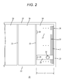
- FIG. 2 illustrates a lead-acid battery 20, where numeral 22 denotes a container, numeral 23 denotes a partition, and six cell chambers 24 are arranged in series.
- Numeral 26 denotes a strap on the negative electrode side
- numeral 27 denotes a strap on the positive electrode side
- numerals 28 and 29 denote cell-connecting conductors
- numeral 30 denotes a pole.
- Numeral 2 denotes the negative electrode plate as mentioned above
- numeral 32 denotes a positive electrode plate
- numeral 34 denotes a separator that may also cover the positive electrode plate 32.
- the concentration of Ba contained in the formed negative active material is quantified as follows.
- a lead-acid battery in a fully charged state is disassembled, the negative electrode plates are washed with water and dried to remove the sulfate content, and the negative active material is collected.
- the negative active material is ground, a 300 g/L hydrogen peroxide solution is added in an amount of 20 mL per 100 g of the negative active material.
- (1+3) nitric acid which is prepared by diluting 60 mass% concentrated nitric acid with three times its volume of ion exchange water, is added and then is heated for 5 hours with stirring, thereby dissolving lead as lead nitrate.
- Ba sulfate is dissolved, and the Ba concentration in the solution is quantified by atomic absorption measurement and converted into the Ba concentration in the negative active material.
- the Ba sulfate concentration in the negative active material can be determined from the Ba concentration in the negative active material.
- the electrolyte solution is extracted from the lead-acid battery in a fully charged state, and each concentration is quantified by ICP analysis.
- the content of graphite in the negative active material is quantified as follows.
- a lead-acid battery in a fully charged state is disassembled, the negative electrode plates are washed with water and dried to remove the sulfate content, and the negative active material is collected.
- the negative active material is ground, a hydrogen peroxide solution having a concentration of 300 g/L is added in an amount of 20 mL per 100 g of the negative active material.
- (1+3) nitric acid which is prepared by diluting 60 mass% concentrated nitric acid with three times its volume of ion exchange water, is added and then is heated for 5 hours with stirring, thereby dissolving lead as lead nitrate.
- solid matters such as graphite, carbon, and the reinforcing material are separated by filtration.
- the solid matters obtained by filtration are dispersed in water.
- the dispersion liquid is sieved twice using a sieve having a size of 1.4 mm to remove the reinforcing material.
- centrifugal separation is performed at 3000 rpm for 5 minutes, and carbon and graphite are extracted from the supernatant and the upper precipitate.
- a centrifugation operation is performed at 3000 rpm for 5 minutes, and the supernatant and precipitate are all passed through a sieve having a size of 20 ⁇ m.
- Graphite does not to pass through the sieve and thus remains on the sieve.
- a large amount of hot water is poured over graphite remaining on the sieve to remove VANILLEX N, followed by washing with water and drying. The graphite washed with water and dried was weighed, and the weight is converted into the content of graphite in the negative active material.
- the quantification method for the density of the positive electrode material is as follows.
- the formed positive electrode material in a fully charged state is washed with water and dried, and the positive electrode material is separated from the positive electrode grid.
- the separated positive electrode material is, in an unground state, measured for the density by the following procedures.
- the obtained lead-acid battery was discharged from the fully charged state at 5-hour rate current for 30 minutes, and then charged at a constant voltage of 14.5 V for 10 seconds, and the quantity of electricity at that time was measured as the charge acceptance performance without standing (without being remained untouched).
- the battery was discharged from the fully charged state at 5-hour rate current for 30 minutes, allowed to stand (be remained untouched) for 12 hours, and then charged at a constant voltage of 14.5 V for 10 seconds, and the quantity of electricity at that time was measured as the charge acceptance performance with standing.
- FIG. 3 is a graph showing the charge acceptance performance of the lead-acid batteries A1 to A24 with standing in Table 1.
- the Na concentration of the electrolyte solution is 0.05 mol/L or 0.10 mol/L
- the Ba sulfate concentration in the negative active material is 1.0 mass% or more, the charge acceptance performance with standing significantly decreases ( FIG. 3 ).
- the charge acceptance performance with standing does not decrease as much as in the case where the Na concentration of the electrolyte solution is 0.05 mol/L or 0.10 mol/L ( FIG. 3 ). Therefore, it can be said that the suppressing effect on a decrease in the charge acceptance performance with standing is high in the case where the Na concentration of the electrolyte solution is 0.04 mol/L or less and the Ba sulfate concentration in the negative active material is 1.0 mass% or more.
- the samples B1 to B5 and the sample A4 in Table 1 show the influence of the total mass NP of negative electrode plates per effective volume V of the cell chamber (NP/V) on the rate of increase in the internal resistance at the 2000 th cycle.
- An increase in the internal resistance in accordance with the progress of charge-discharge cycles was suppressed when NP/V was 1.30 g/cm 3 or more and 1.60 g/cm 3 or less ( FIG. 5 ).
- NP/V was 1.40 g/cm 3 or more and 1.50 g/cm 3 or less
- an increase in the internal resistance in accordance with the progress of charge-discharge cycles was significantly suppressed ( FIG. 5 ).
- NP/V total mass NP of negative electrode plates per effective volume V of the cell chamber
- FIG. 6 shows the influence of the density of the positive active material on the life performance, and NP/V was set at 1.40 g/cm 3 .
- the number of life cycles of a battery in which the Na concentration of the electrolyte solution is 0.1 mol/L, the Ba sulfate concentration in the negative active material is 0.5 mass%, and the density of the positive active material is 3.70 g/cm 3 , as 100, the number of life cycles of each battery is shown.
- the tendency of the life test results is completely different between the case where the Na concentration in the electrolyte solution is 0.04 mol/L or less and the Ba sulfate concentration in the negative active material is 1.0 mass% or more and other cases.
- the number of life cycles of each battery is shown taking the number of life cycles of a battery having no flake graphite contained in the negative active material and no Al or Li contained in the electrolyte solution as 100.
- FIG. 7 shows the influence of the graphite content of the negative active material on the life performance.
- the negative active material contains graphite
- the life performance improves.
- the Na concentration is 0.04 mol/L or less and the Ba sulfate concentration is 1.0 mass% or more
- the life performance is improved even more significantly by the presence of graphite in the negative active material.
- the content of graphite in the negative electrode material is within a range of 0.7 mass% or more, the improving effect on the life performance is particularly significant.
- FIG. 8 shows the influence of the Al concentration of the electrolyte solution on the life performance.
- the electrolyte solution contains Al
- the life performance improves.
- the Na concentration is 0.04 mol/L or less and the Ba sulfate concentration is 1.0 mass% or more
- the life performance is improved even more significantly by the presence of Al in the electrolyte solution.
- the improving effect on the life performance is particularly significant when the concentration of Al in the electrolyte solution is within a range of 0.05 mol/L or more.
- FIG. 9 shows the influence of the Li concentration of the electrolyte solution on the life performance.
- the life performance decreases.
- the Na concentration is 0.04 mol/L or less and the Ba sulfate concentration is 1.0 mass% or more
- the life performance improves when the electrolyte solution contains Li.
- the improving effect on the life performance is particularly significant when the concentration of Li in the electrolyte solution is within a range of 0.05 mol/L or more.
- the tendency of the life test results is completely different between the case where the Na concentration in the electrolyte solution is 0.04 mol/L or less and the Ba sulfate concentration in the negative active material is 1.0 mass% or more and other cases.
- the lead-acid batteries in the Examples are flooded type batteries, they may also be valve-regulated batteries.
- the lead-acid batteries can be used not only for idling-stop vehicles but also for charge-control vehicles, and are suitable as batteries for use under PSOC (Partial State of Charge) conditions.
- PSOC Partial State of Charge
Landscapes
- Chemical & Material Sciences (AREA)
- Chemical Kinetics & Catalysis (AREA)
- Electrochemistry (AREA)
- General Chemical & Material Sciences (AREA)
- Engineering & Computer Science (AREA)
- Manufacturing & Machinery (AREA)
- Inorganic Chemistry (AREA)
- Battery Electrode And Active Subsutance (AREA)
- Secondary Cells (AREA)
Abstract
Description
- The present invention relates to a lead-acid battery.
-
JP-A-2012-142185 - In addition, for the electrode material of the negative electrode, 0.6 mass% of Ba sulfate is contained relative to 98.8 mass% of a lead powder. However, changing the Ba sulfate concentration from 0.6 mass% has not been considered.
- In
JP-A-2001-23682 -
JP-A-2003-178806 - In a mode like an idling-stop mode, a lead-acid battery is not sufficiently charged, and thus the crystallization of lead sulfate is likely to proceed in the negative active material. In addition, the battery is not charged to generate a large amount of gas, and thus the electrolyte solution is likely to be stratified. When the electrolyte solution is stratified, some electrode plates are used locally, causing a further decrease in the life performance.
- In order to solve these problems, it is necessary to improve the charge acceptance performance and suppress the crystallization of lead sulfate. Ba sulfate improves the charge acceptance performance in the case where the battery is charged without being remained untouched after the discharge. However, it has been revealed that in the case where the battery is charged after some time has passed since the discharge, the charge acceptance performance is reduced by Ba sulfate. In order to suppress the crystallization of lead sulfate, the charge acceptance performance immediately after discharge and that after being remained untouched are both important. In addition, internal resistance is an important index, which indicates the degradation state of the lead-acid battery, and is also used to determine whether idling-stop is possible in idling-stop vehicles. When there is a small increase in the internal resistance in accordance with the progress of charge-discharge cycles, this indicates that the degradation of electrode plates is slow, the degradation of electrode plates is uniformly progressing, etc.
- The present invention is aimed at providing a lead-acid battery whose charge acceptance performance does not decrease much even in the case where the battery is charged after some time has passed since the discharge.
- An aspect of the present invention provides a lead-acid battery including a positive electrode plate, a negative electrode plate, and an electrolyte solution placed in a cell chamber of a container. In a negative electrode material of the negative electrode plate, the concentration of Ba sulfate contained in the electrode material after full charge is 1.0 mass% or more, and the Na concentration in the electrolyte solution is 0.04 mol/L or less.
-
-
FIG. 1 is a front view of a negative electrode plate. -
FIG. 2 is a plan view of part of a lead-acid battery with a lid removed. -
FIG. 3 is a characteristic diagram showing the charge acceptance performance with being remained untouched (standing) under conditions where NP/V is fixed to 1.40 g/cm3, the Na concentration is varied within a range of 0.015 mol/L to 0.1 mol/L, and the Ba sulfate concentration is varied within a range of 0.5 mass% to 4 mass% (expressed as a value relative to the charge acceptance performance in the case where the Ba sulfate concentration is 0.5 mass% at each Na concentration (= 100)). -
FIG. 4 is a characteristic diagram showing the rate of increase in the internal resistance at the 2000th cycle under conditions where NP/V is fixed to 1.40 g/cm3, the Na concentration is varied within a range of 0.015 mol/L to 0.1 mol/L, and the Ba sulfate concentration is varied within a range of 0.5 mass% to 4 mass%. -
FIG. 5 is a characteristic diagram showing the rate of increase in the internal resistance at the 2000th cycle under conditions where NP/V is varied within a range of 1.25 g/cm3 to 1.70 g/cm3. -
FIG. 6 is a characteristic diagram showing the number of life cycles under conditions where the density of the positive electrode material is varied within a range of 3.7 g/cm3 to 4.2 g/cm3. -
FIG. 7 is a characteristic diagram showing the number of life cycles under conditions where graphite is contained in the negative electrode material. -
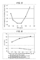
FIG. 8 is a characteristic diagram showing the number of life cycles under conditions where Al is contained in the electrolyte solution. -
FIG. 9 is a characteristic diagram showing the number of life cycles under conditions where Li is contained in the electrolyte solution. - According to an aspect of the present invention, there is provided a lead-acid battery including a positive electrode plate, a negative electrode plate, and an electrolyte solution placed in a cell chamber of a container, in a negative electrode material of the negative electrode plate, the concentration of Ba sulfate contained in the electrode material after full charge is 1.0 mass% or more, and the Na concentration in the electrolyte solution is 0.04 mol/L or less.
- An increase in the Ba sulfate concentration in the negative electrode material results in the improvement of the charge acceptance performance in the case where the battery is charged without standing following discharge. However, the present inventors have found that when only the Ba sulfate concentration is increased, in the case where the battery is charged after standing following discharge, the charge acceptance performance rather decreases. Further, to deal with this, the present inventors have found that when the Na concentration in the electrolyte solution is 0.04 mol/L or less, a decrease in the charge acceptance performance after standing due to the addition of Ba sulfate can be suppressed (
FIG. 3 ). That is, when the Na concentration in the electrolyte solution is limited to 0.04 mol/L or less, and the Ba sulfate concentration in the negative electrode material is 1.0 mass% or more, a lead-acid battery, in which a decrease in the charge acceptance performance in the case where the battery is charged after standing following discharge is suppressed, is obtained. In conventional lead-acid batteries, in order to suppress a penetration short circuit, the Na concentration in the electrolyte solution is generally made about 0.1 mol/L to 0.2 mol/L. Therefore, it is not easy to conceive of a Na concentration of 0.04 mol/L or less. - Further, when the Na concentration in the electrolyte solution is limited to 0.04 mol/L or less, and the Ba sulfate concentration in the negative electrode material is 1.2 mass% or more, an increase in the internal resistance of a lead-acid battery in accordance with the progress of charge-discharge cycles when used under PSOC (Partial State of Charge) conditions can be suppressed (
FIG. 4 ). Meanwhile, even when the Na concentration in the electrolyte solution is limited to 0.04 mol/L or less, if the Ba sulfate concentration in the negative electrode material is 1.0 mass% or less, the suppressing effect on an increase in the internal resistance in accordance with the progress of charge-discharge cycles is small. Thus, the tendency is significantly different between Ba sulfate concentrations of 1.0 mass% or less and 1.2 mass% or more (FIG. 4 ). In addition, in the case where the Na concentration in the electrolyte solution is more than 0.04 mol/L, even when the Ba sulfate concentration in the negative electrode material is 1.2 mass% or more, the rate of increase in the internal resistance in accordance with the progress of charge-discharge cycles does not significantly change (FIG. 4 ). It has been heretofore unknown that an increase in the internal resistance in accordance with the progress of charge-discharge cycles is suppressed in the case where the Ba sulfate concentration in the negative electrode material is 1.2 mass% or more and the Na concentration in the electrolyte solution is 0.04 mol/L or less. Thus, this is an unexpected result. - Incidentally, in place of Ba sulfate, it is also possible to use elemental Ba or a Ba compound such as Ba carbonate. This is because even when elemental Ba or a Ba compound is added to the negative electrode material, it turns into Ba sulfate after addition. Elemental Ba or a Ba compound is added such that the concentration in terms of Ba sulfate will be 1.0 mass% or more, preferably 1.2 mass% or more, relative to the mass of the negative electrode material after full charge. As a concentration in terms of Ba, addition is made such that the concentration will be 0.6 mass% or more, preferably 0.7 mass% or more, relative to the mass of the negative electrode material after full charge.
- When the Ba sulfate concentration in the negative electrode material is more than 4.0 mass%, the paste of the negative electrode material becomes so hard that it is difficult to apply the paste to a negative electrode current collector. Therefore, it is preferable that the Ba sulfate concentration in the negative electrode material after full charge is 4.0 mass% or less, more preferably 3.5 mass% or less. As a concentration in terms of Ba, it is preferable that the concentration is 2.4 mass% or less, more preferably 2.1 mass% or less, relative to the mass of the negative electrode material after full charge.
- The Na concentration of the electrolyte solution is the lower the better. In the aspect of the present invention, the Na concentration is 0.04 mol/L or less, preferably 0.035 mol/L or less. Na is mixed in from lignin or the like added to the negative electrode material. Therefore, it is difficult to make the
Na concentration 0, and the concentration is practically 0.001 mol/L or more. When the Na concentration is limited, it becomes necessary to reduce the amount of lignin or the like added to the negative electrode material, resulting in a decrease in the life performance of the lead-acid battery. Therefore, it is more preferable that the Na concentration is 0.005 mol/L or more. In addition, Li, Al, and the like in the electrolyte solution do not inhibit the effect of Ba sulfate (improvement of charge acceptance performance), and thus their contents are arbitrary. - When the total mass of negative electrode plates in a cell chamber is expressed as NP (g), and the volume defined by the height h (cm) of the negative electrode plates x the width w (cm) of the negative electrode plates x the inside dimension d (cm) of the cell chamber in a direction perpendicular to the negative electrode plates is expressed as V (V = hwd), it is preferable that NP/V is 1.3 g/cm3 or more and 1.6 g/cm3 or less. It is more preferable that NP/V is 1.4 g/cm3 or more and 1.5 g/cm3 or less. Incidentally, the height and width of a negative electrode plate are determined ignoring the parts projecting from the negative electrode plate, such as lugs and feet.
- When the Ba sulfate concentration in the negative electrode material and the Na concentration of the electrolyte solution are determined as described above (according to the aspect of the present invention), and NP/V is 1.3 g/cm3 or more and 1.6 g/cm3 or less, an increase in the internal resistance in accordance with the progress of charge-discharge cycles can be suppressed (
FIG. 5 ). When NP/V is 1.4 g/cm3 or more and 1.5 g/cm3 or less, an increase in the internal resistance in accordance with the progress of charge-discharge cycles can be even more suppressed (FIG. 5 ). It has been heretofore unknown that NP/V is associated with an increase in the internal resistance in accordance with the progress of charge-discharge cycles. Therefore, it can be said that it is an unexpected result that an increase in the internal resistance with the progress of charge-discharge cycles can be suppressed by making NP/V 1.3 g/cm3 or more and 1.6 g/cm3 or less, preferably 1.4 g/cm3 or more and 1.5 g/cm3 or less. - It is preferable that the density of the positive electrode material is 3.8 g/cm3 or more, more preferably 3.9 g/cm3 or more. In the case where the Ba sulfate concentration in the negative electrode material is 1.0 mass% or more, and the Na concentration in the electrolyte solution is 0.04 mol/L or less, when the density of the positive electrode material is 3.8 g/cm3 or more, the life performance of the lead-acid battery significantly improves (
FIG. 6 ). Meanwhile, not in the case where the Ba sulfate concentration in the negative electrode material is 1.0 mass% or more and the Na concentration in the electrolyte solution is 0.04 mol/L or less, when the density of the positive electrode material is 3.8 g/cm3 or more, the life performance of the lead-acid battery rather decreases (FIG. 6 ). It is an unexpected result that only in the case where the Ba sulfate concentration in the negative electrode material is 1.0 mass% or more and the Na concentration in the electrolyte solution is 0.04 mol/L or less, the life performance is improved by making the density of the positive electrode material 3.8 g/cm3 or more. - When the density of the positive electrode material is more than 5.0 g/cm3, the influence of a decrease in the capacity of the lead-acid battery becomes non-negligible. Therefore, it is preferable that the density of the positive electrode material is 5.0 g/cm3 or less, more preferably 4.3 g/cm3 or less, and particularly preferably 4.2 g/cm3 or less.
- It is preferable that the negative electrode material contains graphite. Graphite in the negative electrode material significantly improves the life performance of the lead-acid battery in the case where the Ba sulfate concentration in the negative electrode material is 1.0 mass% or more and the Na concentration in the electrolyte solution is 0.04 mol/L or less. Even not in the case where the Ba sulfate concentration in the negative electrode material is 1.0 mass% or more and the Na concentration in the electrolyte solution is 0.04 mol/L or less, the life performance is improved by the presence of graphite in the negative electrode material (
FIG. 7 ). However, the improving effect on the life performance caused by the presence of graphite in the negative electrode material is remarkable in the case where the Ba sulfate concentration in the negative electrode material is 1.0 mass% or more and the Na concentration in the electrolyte solution is 0.04 mol/L or less (FIG. 7 ). It is an unexpected result that in the case where the Ba sulfate concentration in the negative electrode material is 1.0 mass% or more and the Na concentration in the electrolyte solution is 0.04 mol/L or less, the improving effect on the life performance caused by the presence of graphite in the negative electrode material is remarkable. - When the content of graphite in the negative electrode material is 0.5 mass% or more, the improving effect on the life performance is significant, and thus this is preferable. When the content of graphite in the negative electrode material is 0.7 mass% or more, the improving effect on the life performance is more significant, and thus this is more preferable. In addition, it is preferable that the graphite is flake graphite.
- When the content of graphite in the negative electrode material is more than 2.5 mass%, the paste of the negative electrode material becomes so hard that it is difficult to apply the paste to the negative electrode current collector. Therefore, it is preferable that the content of graphite in the negative electrode material is 2.5 mass% or less, more preferably 2.0 mass% or less.
- It is preferable that the electrolyte solution contains Al. Al in the electrolyte solution significantly improves the life performance of the lead-acid battery in the case where the Ba sulfate concentration in the negative electrode material is 1.0 mass% or more and the Na concentration in the electrolyte solution is 0.04 mol/L or less. Even not in the case where the Ba sulfate concentration in the negative electrode material is 1.0 mass% or more and the Na concentration in the electrolyte solution is 0.04 mol/L or less, the life performance is improved by the presence of Al in the electrolyte solution (
FIG. 8 ). However, the improving effect on the life performance caused by the presence of Al in the electrolyte solution is remarkable in the case where the Ba sulfate concentration in the negative electrode material is 1.0 mass% or more and the Na concentration in the electrolyte solution is 0.04 mol/L or less (FIG. 8 ). It is an unexpected result that in the case where the Ba sulfate concentration in the negative electrode material is 1.0 mass% or more and the Na concentration in the electrolyte solution is 0.04 mol/L or less, the improving effect on the life performance caused by the presence of Al in the electrolyte solution is remarkable. - When the Al concentration in the electrolyte solution is 0.02 mol/L or more, the improving effect on the life performance is significant, and thus this is preferable. When the Al concentration in the electrolyte solution is 0.05 mol/L or more, the improving effect on the life performance is more significant, and thus this is more preferable. In addition, when the Al concentration in the electrolyte solution is 0.2 mol/L or less, the improving effect on the life performance is significant, and thus this is preferable. When the Al concentration in the electrolyte solution is 0.15 mol/L or less, the improving effect on the life performance is more significant, and thus this is more preferable.
- It is preferable that the electrolyte solution contains Li. Li in the electrolyte solution improves the life performance of the lead-acid battery in the case where the Ba sulfate concentration in the negative electrode material is 1.0 mass% or more and the Na concentration in the electrolyte solution is 0.04 mol/L or less (
FIG. 9 ). Meanwhile, not in the case where the Ba sulfate concentration in the negative electrode material is 1.0 mass% or more and the Na concentration in the electrolyte solution is 0.04 mol/L or less, the life performance of the lead-acid battery rather decreases when Li is contained in the electrolyte solution (FIG. 9 ). It is an unexpected result that only in the case where the Ba sulfate concentration in the negative electrode material is 1.0 mass% or more and the Na concentration in the electrolyte solution is 0.04 mol/L or less, the life performance is improved by the presence of Li in the electrolyte solution. - When the Li concentration in the electrolyte solution is 0.02 mol/L or more, the improving effect on the life performance is significant, and thus this is preferable. When the Li concentration in the electrolyte solution is 0.05 mol/L or more, the improving effect on the life performance is still more significant, and thus this is more preferable. When the Li concentration in the electrolyte solution is 0.1 mol/L or more, the improving effect on the life performance is still more significant, and thus this is still more preferable.
- When the Li concentration in the electrolyte solution is more than 0.2 mol/L, the charge acceptance performance decreases. Therefore, it is preferable that the Li concentration in the electrolyte solution is 0.2 mol/L or less, more preferably 0.15 mol/L or less.
- The lead-acid battery according to the aspect of the present invention is excellent in terms of charge acceptance performance both immediately after discharge and after standing, and thus is suitable for use as a lead-acid battery for idling-stop and the like, which is not sufficiently charged.
- Hereinafter, examples will be shown. To implement the invention, the examples may be suitably modified according to the common knowledge of those skilled in the art and the disclosure of related art. Incidentally, in the examples, a negative electrode material may be referred to as a negative active material, while a positive electrode material may be referred to as a positive active material. In addition, a negative electrode plate is made of a negative electrode current collector (negative electrode grid) and a negative electrode material (negative active material), while a positive electrode plate is made of a positive current collector (positive electrode grid) and a positive electrode material (positive active material). Solid constituents other than the current collectors (grids) belong to electrode materials (active materials).
- The concentrations of Ba sulfate and graphite in the negative electrode material and Na, Al, Li, and like additives in the electrolyte solution, the density of the positive electrode material, and the like are values in a fully charged state. Incidentally, a fully charged state is a state in which the battery has been charged at 5-hour rate current until the terminal voltage during discharge measured every 15 minutes shows a constant value 3 times in a row.
- A negative active material was prepared by mixing a lead powder, which was obtained by a ball-mill method, with a predetermined amount of Ba sulfate (average primary particle size: 0.79 µm, average secondary particle size: 2.5 µm), carbon, lignin, and plastic fibers as a reinforcing material to make the total 100 mass% with the lead powder. The Ba sulfate concentration was varied within a range of 0.5 mass% to 4.0 mass% relative to the amount of negative active material after full charge. The lignin content was 0.2 mass%, but the concentration is arbitrary. In addition, the production method for the lead powder, the oxygen content, and the like are arbitrary, and other additives, water-soluble synthetic polyelectrolytes, and the like may also be contained. Incidentally, in place of Ba sulfate, it is also possible to use elemental Ba or a Ba compound such as Ba carbonate.
- The mixture was pasted with water and sulfuric acid, and the paste was applied to and filled in an expanded negative electrode grid made of a Pb-Ca-Sn-based alloy, then aged, and dried. Incidentally, the amount of water at the time of pasting and applying conditions were varied to adjust the density and thickness of the negative active material, thereby adjusting the mass of the negative electrode plate. In addition, the negative electrode grid may be a cast grid, a punched grid, or the like.
- The mass of the negative electrode plate was adjusted by adjusting the mass of the negative active material, but may also be adjusted by adjusting the mass of the negative electrode grid by adjusting the width, the number, or the like of crosspieces of the negative electrode grid. An increase in the mass of the negative active material and an increase in the mass of the negative electrode grid have the same effects.
- A positive active material was prepared by mixing a lead powder, which was obtained by a ball-mill method, with plastic fibers as a reinforcing material, and the mixture was pasted with water and sulfuric acid. The paste was applied to an expanded positive electrode grid made of a Pb-Ca-Sn-based alloy, then aged, and dried. Incidentally, the amount of water at the time of pasting was varied to adjust the density of the positive active material. In addition, the positive electrode grid may be a cast grid, a punched grid, or the like.
- Unformed (not yet subjected to formation) negative electrode plates were each covered with a polyethylene separator. Six unformed negative electrode plates and five unformed positive electrode plates were alternately layered, and the negative electrode plates and the positive electrode plates were each connected with a strap to make an element. In addition, the thickness of the separator was adjusted according to changes in the thickness of the negative electrode plates caused by the adjustment of the mass of the negative electrode plates. Incidentally, it is also possible to cover positive electrode plates with a separator. The element was placed in a cell chamber of the container, and sulfuric acid having a specific gravity of 1.230 was added at 20°C to perform container formation, thereby giving a flooded type lead-acid battery of B20 size. It may also be a valve-regulated lead-acid battery. After formation, a predetermined amount of sodium sulfate was added to the electrolyte solution, and the Na concentration of the electrolyte solution was adjusted within a range of 0.015 mol/L to 0.10 mol/L.
-
FIG. 1 illustrates anegative electrode plate 2, wherenumerals 4 and 6 denote upper and lower frames, numeral 8 denotes a crosspiece, and numeral 10 denotes a negative active material.Numeral 12 denotes a lug and numeral 13 denotes a foot. The height of the grid excluding thelug 12 and thefeet 13 is defined as the height h of thenegative electrode plate 2, and the width of thenegative electrode plate 2 is expressed as w. If there is a projection in the width direction, the width w is determined excluding the projection. -
FIG. 2 illustrates a lead-acid battery 20, where numeral 22 denotes a container, numeral 23 denotes a partition, and sixcell chambers 24 are arranged in series.Numeral 26 denotes a strap on the negative electrode side, numeral 27 denotes a strap on the positive electrode side,numerals Numeral 2 denotes the negative electrode plate as mentioned above, numeral 32 denotes a positive electrode plate, and numeral 34 denotes a separator that may also cover thepositive electrode plate 32. The inside dimension of thecell chamber 24 in the direction perpendicular to theplates negative electrode plates 2, and the width w of the negative electrode plates, the effective volume V of thecell chamber 24 is defined as V = hwd. - The concentration of Ba contained in the formed negative active material is quantified as follows. A lead-acid battery in a fully charged state is disassembled, the negative electrode plates are washed with water and dried to remove the sulfate content, and the negative active material is collected. The negative active material is ground, a 300 g/L hydrogen peroxide solution is added in an amount of 20 mL per 100 g of the negative active material. Further, (1+3) nitric acid, which is prepared by diluting 60 mass% concentrated nitric acid with three times its volume of ion exchange water, is added and then is heated for 5 hours with stirring, thereby dissolving lead as lead nitrate. Furthermore, Ba sulfate is dissolved, and the Ba concentration in the solution is quantified by atomic absorption measurement and converted into the Ba concentration in the negative active material. The Ba sulfate concentration in the negative active material can be determined from the Ba concentration in the negative active material.
- For the concentrations of Na, Al, and Li in the electrolyte solution, the electrolyte solution is extracted from the lead-acid battery in a fully charged state, and each concentration is quantified by ICP analysis.
- The content of graphite in the negative active material is quantified as follows. A lead-acid battery in a fully charged state is disassembled, the negative electrode plates are washed with water and dried to remove the sulfate content, and the negative active material is collected. The negative active material is ground, a hydrogen peroxide solution having a concentration of 300 g/L is added in an amount of 20 mL per 100 g of the negative active material. Further, (1+3) nitric acid, which is prepared by diluting 60 mass% concentrated nitric acid with three times its volume of ion exchange water, is added and then is heated for 5 hours with stirring, thereby dissolving lead as lead nitrate. Next, solid matters such as graphite, carbon, and the reinforcing material are separated by filtration.
- The solid matters obtained by filtration are dispersed in water. The dispersion liquid is sieved twice using a sieve having a size of 1.4 mm to remove the reinforcing material. Next, centrifugal separation is performed at 3000 rpm for 5 minutes, and carbon and graphite are extracted from the supernatant and the upper precipitate.
- Next, the extracted carbon and graphite are separated. 15 mL of VANILLEX N manufactured by Nippon Paper Industries Co., Ltd., is added per 100 mL of the supernatant and upper precipitate extracted, followed by a stirring operation.
- After the above operation, a centrifugation operation is performed at 3000 rpm for 5 minutes, and the supernatant and precipitate are all passed through a sieve having a size of 20 µm. Graphite does not to pass through the sieve and thus remains on the sieve. A large amount of hot water is poured over graphite remaining on the sieve to remove VANILLEX N, followed by washing with water and drying. The graphite washed with water and dried was weighed, and the weight is converted into the content of graphite in the negative active material.
- The quantification method for the density of the positive electrode material is as follows. The formed positive electrode material in a fully charged state is washed with water and dried, and the positive electrode material is separated from the positive electrode grid. The separated positive electrode material is, in an unground state, measured for the density by the following procedures.
- a) The apparent density (g/cm3) of the positive electrode material including closed pores is measured by a pycnometer method.
- b) The open pore volume per unit mass (cm3/g) of the positive electrode material is measured by a mercury intrusion method. In the mercury intrusion method, pressure is applied to the maximum pressure of 4.45 psia (30.7KPa), the contact angle is set to be 130°, and the mercury surface tension is set to be 484 dynes/cm.
- c) The density of the positive electrode material is determined as follows: 1 ÷ [(1 ÷ apparent density of positive electrode material) + (open pore volume per unit mass of positive electrode material)]. As mentioned above, the density of the positive electrode material is the density of the closed pores, open pores, and the positive electrode material in the formed positive electrode material after full charge.
- The obtained lead-acid battery was discharged from the fully charged state at 5-hour rate current for 30 minutes, and then charged at a constant voltage of 14.5 V for 10 seconds, and the quantity of electricity at that time was measured as the charge acceptance performance without standing (without being remained untouched). In addition, the battery was discharged from the fully charged state at 5-hour rate current for 30 minutes, allowed to stand (be remained untouched) for 12 hours, and then charged at a constant voltage of 14.5 V for 10 seconds, and the quantity of electricity at that time was measured as the charge acceptance performance with standing.
- As a life test, a 1000-cycle test was performed in one week in accordance with the standard of Battery Association of Japan (SBA S0101 9.4.5) modified as follows:
- a cycle including discharge at 1-hour rate current for 59 seconds, discharge at 300 A for 1 second, and charge at 14 V for 60 seconds was performed;
- a pause of 2 hours was given every 30 cycles; and
- the internal resistance was measured every 1000 cycles. Incidentally, the internal resistance was measured by an alternating current four-probe method. Then, when the discharge voltage became less than 7.2 V, it was defined as the life. The results are shown in Table 1 and
FIGS. 3 to 5 . The charge acceptance performance (with standing and without standing) and the number of life cycles are expressed as values relative to the sample A19 in Table 1 as 100 (comparative example in which NP/V is 1.40 g/cm3, the Na concentration is 0.10 mol/L, and Ba sulfate is 0.5 mass%). In addition, the internal resistance is expressed as a value relative to the internal resistance of each lead-acid battery before the life test as 1. - Table 1 shows that with an increase in the concentration of Ba sulfate contained in the negative active material, the charge acceptance performance with standing improves, but the charge acceptance performance with standing decreases.
FIG. 3 is a graph showing the charge acceptance performance of the lead-acid batteries A1 to A24 with standing in Table 1. The charge acceptance performance is expressed as a value relative to the charge acceptance performance with standing of each lead-acid battery having a Ba sulfate concentration of 0.5 mass% at each Na concentration (= 100). In the case where the Na concentration of the electrolyte solution is 0.05 mol/L or 0.10 mol/L, when the Ba sulfate concentration in the negative active material is 1.0 mass% or more, the charge acceptance performance with standing significantly decreases (FIG. 3 ). Meanwhile, in the case where the Na concentration of the electrolyte solution is 0.015 mol/L or 0.035 mol/L, even when the Ba sulfate concentration in the negative active material is 1.0 mass% or more, the charge acceptance performance with standing does not decrease as much as in the case where the Na concentration of the electrolyte solution is 0.05 mol/L or 0.10 mol/L (FIG. 3 ). Therefore, it can be said that the suppressing effect on a decrease in the charge acceptance performance with standing is high in the case where the Na concentration of the electrolyte solution is 0.04 mol/L or less and the Ba sulfate concentration in the negative active material is 1.0 mass% or more. It has been heretofore unknown that the suppressing effect on a decrease in the charge acceptance performance with standing is high in the case where the Na concentration of the electrolyte solution is 0.04 mol/L or less and the Ba sulfate concentration in the negative active material is 1.0 mass% or more. Thus, this was an unexpected result. - Further, in the case where the Na concentration in the electrolyte solution was 0.04 mol/L or less, when the Ba sulfate concentration in the negative active material was 1.2 mass% or more, the rate of increase in the internal resistance at the 2000th cycle was significantly suppressed (
FIG. 4 ). Meanwhile, even not in the case where the Na concentration in the electrolyte solution was 0.04 mol/L or less, when the Ba sulfate concentration in the negative active material was 1.0 mass%, the suppressing effect on the rate of increase in the internal resistance at the 2000th cycle was small. Thus, the tendency was significantly different between Ba sulfate concentrations of 1.0 mass% or less and 1.2 mass% or more (FIG. 4 ). In addition, in the case where the Na concentration in the electrolyte solution was more than 0.04 mol/L, even when the Ba sulfate concentration in the negative active material was 1.2 mass% or more, the rate of increase in the internal resistance at the 2000th cycle did not change much (FIG. 4 ). It has been heretofore unknown that an increase in the internal resistance in accordance with the progress of charge-discharge cycles is suppressed in the case where the Na concentration in the electrolyte solution is 0.04 mol/L or less and the Ba sulfate concentration in the negative active material is 1.2 mass% or more. Thus, this was an unexpected result. - The samples B1 to B5 and the sample A4 in Table 1 show the influence of the total mass NP of negative electrode plates per effective volume V of the cell chamber (NP/V) on the rate of increase in the internal resistance at the 2000th cycle. An increase in the internal resistance in accordance with the progress of charge-discharge cycles was suppressed when NP/V was 1.30 g/cm3 or more and 1.60 g/cm3 or less (
FIG. 5 ). In particular, when NP/V was 1.40 g/cm3 or more and 1.50 g/cm3 or less, an increase in the internal resistance in accordance with the progress of charge-discharge cycles was significantly suppressed (FIG. 5 ). It has been heretofore unknown that the total mass NP of negative electrode plates per effective volume V of the cell chamber (NP/V) affects the rate of increase in the internal resistance in accordance with the progress of charge-discharge cycles. Therefore, it is an unexpected result that an increase in the internal resistance in accordance with the progress of charge-discharge cycles can be significantly suppressed when NP/V is 1.30 g/cm3 or more and 1.60 g/cm3 or less, preferably 1.40 g/cm3 or more and 1.50 g/cm3 or less. -
FIG. 6 shows the influence of the density of the positive active material on the life performance, and NP/V was set at 1.40 g/cm3. Taking the number of life cycles of a battery, in which the Na concentration of the electrolyte solution is 0.1 mol/L, the Ba sulfate concentration in the negative active material is 0.5 mass%, and the density of the positive active material is 3.70 g/cm3, as 100, the number of life cycles of each battery is shown. In the case where the Na concentration in the electrolyte solution was 0.04 mol/L or less and the Ba sulfate concentration in the negative active material was 1.0 mass% or more, when the density of the positive active material was 3.80 g/cm3 or more, the number of life cycles increased (FIG. 6 ). In particular, when the density of the positive active material was 3.90 g/cm3 or more, the number of life cycles significantly increased. Meanwhile, in the case where the Na concentration was 0.1 mol/L and the Ba sulfate concentration was 0.5 mass%, when the density of the positive active material was 3.80 g/cm3 or more, the number of life cycles decreased (FIG. 6 ). Therefore, it can be said that under conditions where the density of the positive active material is 3.80 g/cm3 or more, the tendency of the life test results is completely different between the case where the Na concentration in the electrolyte solution is 0.04 mol/L or less and the Ba sulfate concentration in the negative active material is 1.0 mass% or more and other cases. - The effect of the addition of graphite to the negative active material and the effect of the addition of Al and Li to the electrolyte solution were examined. As comparative examples, under conditions where the Na concentration of the electrolyte solution was 0.1 mol/L and the Ba sulfate concentration in the negative active material was 0.5 mass%, lead-acid batteries having flake graphite contained in the negative active material and lead-acid batteries having Al or Li contained in the electrolyte solution were produced. In addition, as examples, under conditions where the Na concentration in the electrolyte solution was 0.015 mol/L and the Ba sulfate concentration in the negative active material was 2.0 mass%, lead-acid batteries having flake graphite contained in the negative active material and lead-acid batteries having Al or Li contained in the electrolyte solution were produced. The production conditions were the same as in Example A4 and Comparative Example A19, except for the concentrations of flake graphite, Al, and Li. The test results of these batteries are shown in
FIGS. 7 to 9 . Incidentally, inFIGS. 7 to 9 , with respect to each of the case where the Na concentration of the electrolyte solution was 0.1 mol/L and the Ba sulfate concentration in the negative active material was 0.5 mass% and the case where the Na concentration in the electrolyte solution was 0.015 mol/L and the Ba sulfate concentration in the negative active material was 2.0 mass%, the number of life cycles of each battery is shown taking the number of life cycles of a battery having no flake graphite contained in the negative active material and no Al or Li contained in the electrolyte solution as 100. -
FIG. 7 shows the influence of the graphite content of the negative active material on the life performance. When the negative active material contains graphite, even in the case where the Na concentration in the electrolyte solution is high and the Ba sulfate concentration in the negative active material is low, the life performance improves. However, in the case where the Na concentration is 0.04 mol/L or less and the Ba sulfate concentration is 1.0 mass% or more, the life performance is improved even more significantly by the presence of graphite in the negative active material. When the content of graphite in the negative electrode material is within a range of 0.7 mass% or more, the improving effect on the life performance is particularly significant. It has been heretofore unknown that the improving effect on the life performance caused by the presence of graphite in the negative electrode material is remarkable in the case where the Na concentration in the electrolyte solution is 0.04 mol/L or less and the Ba sulfate concentration in the negative electrode material is 1.0 mass% or more. Thus, this is an unexpected result. -
FIG. 8 shows the influence of the Al concentration of the electrolyte solution on the life performance. When the electrolyte solution contains Al, even in the case where the Na concentration in the electrolyte solution is high and the Ba sulfate concentration in the negative active material is low, the life performance improves. However, in the case where the Na concentration is 0.04 mol/L or less and the Ba sulfate concentration is 1.0 mass% or more, the life performance is improved even more significantly by the presence of Al in the electrolyte solution. The improving effect on the life performance is particularly significant when the concentration of Al in the electrolyte solution is within a range of 0.05 mol/L or more. It has been heretofore unknown that the improving effect on the life performance caused by the presence of Al in the electrolyte solution is remarkable in the case where the Na concentration in the electrolyte solution is 0.04 mol/L or less and the Ba sulfate concentration in the negative electrode material is 1.0 mass% or more. Thus, this is an unexpected result. -
FIG. 9 shows the influence of the Li concentration of the electrolyte solution on the life performance. When the electrolyte solution contains Li, in the case where the Na concentration in the electrolyte solution is high and the Ba sulfate concentration in the negative active material is low, the life performance decreases. Meanwhile, in the case where the Na concentration is 0.04 mol/L or less and the Ba sulfate concentration is 1.0 mass% or more, the life performance improves when the electrolyte solution contains Li. The improving effect on the life performance is particularly significant when the concentration of Li in the electrolyte solution is within a range of 0.05 mol/L or more. Therefore, it can be said that under conditions where the electrolyte solution contains Li, the tendency of the life test results is completely different between the case where the Na concentration in the electrolyte solution is 0.04 mol/L or less and the Ba sulfate concentration in the negative active material is 1.0 mass% or more and other cases. - Although the lead-acid batteries in the Examples are flooded type batteries, they may also be valve-regulated batteries. In addition, the lead-acid batteries can be used not only for idling-stop vehicles but also for charge-control vehicles, and are suitable as batteries for use under PSOC (Partial State of Charge) conditions. However, the application is arbitrary.
| NP/V (g/cm3) | Na concentration (mol/L) | Ba Sulfate concentration (mass%) | Charge acceptance performance | Rate of increase in internal resistance | Life cycle, relative to A19 | Remarks | ||
| Without standing, relative to A19 | With standing, relative to A19 | |||||||
| A1 | 1.40 | 0.015 | 0.5 | 115 | 123 | 1.10 | 116 | Comparative example |
| A2 | 1.40 | 0.015 | 1.0 | 118 | 121 | 1.09 | 119 | Example |
| A3 | 1.40 | 0.015 | 1.2 | 118 | 119 | 1.07 | 128 | Example |
| A4 | 1.40 | 0.015 | 2.0 | 122 | 117 | 1.06 | 134 | Example |
| A5 | 1.40 | 0.015 | 3.0 | 124 | 116 | 1.07 | 135 | Example |
| A6 | 1.40 | 0.015 | 4.0 | 125 | 115 | 1.06 | 135 | Example |
| A7 | 1.40 | 0.035 | 0.5 | 112 | 117 | 1.14 | 113 | Comparative example |
| A8 | 1.40 | 0.035 | 1.0 | 115 | 113 | 1.13 | 116 | Example |
| A9 | 1.40 | 0.035 | 1.2 | 116 | 112 | 1.10 | 123 | Example |
| A10 | 1.40 | 0.035 | 2.0 | 119 | 111 | 1.10 | 128 | Example |
| A11 | 1.40 | 0.035 | 3.0 | 121 | 108 | 1.09 | 129 | Example |
| A12 | 1.40 | 0.035 | 4.0 | 121 | 107 | 1.09 | 128 | Example |
| A13 | 1.40 | 0.05 | 0.5 | 106 | 110 | 1.20 | 108 | Comparative example |
| A14 | 1.40 | 0.05 | 1.0 | 111 | 103 | 1.19 | 111 | Comparative example |
| A15 | 1.40 | 0.05 | 1.2 | 112 | 101 | 1.19 | 117 | Comparative example |
| A16 | 1.40 | 0.05 | 2.0 | 117 | 96 | 1.19 | 119 | Comparative example |
| A17 | 1.40 | 0.05 | 3.0 | 120 | 89 | 1.18 | 119 | Comparative Example |
| A18 | 1.40 | 0.05 | 4.0 | 121 | 88 | 1.18 | 119 | Comparative example |
| A19 | 1.40 | 0.10 | 0.5 | 100 | 100 | 1.21 | 100 | Comparative example |
| A20 | 1.40 | 0.10 | 1.0 | 105 | 94 | 1.20 | 103 | Comparative Example |
| A21 | 1.40 | 0.10 | 1.2 | 106 | 92 | 1.20 | 106 | Comparative example |
| A22 | 1.40 | 0.10 | 2.0 | 110 | 87 | 1.20 | 108 | Comparative example |
| A23 | 1.40 | 0.10 | 3.0 | 113 | 81 | 1.19 | 110 | Comparative Example |
| A24 | 1.40 | 0.10 | 4.0 | 114 | 80 | 1.19 | 112 | Comparative Example |
| B1 | 1.25 | 0.015 | 2.0 | 120 | 115 | 1.12 | 116 | Example |
| B2 | 1.30 | 0.015 | 2.0 | 121 | 115 | 1.08 | 126 | Example |
| B3 | 1.50 | 0.015 | 2.0 | 123 | 118 | 1.06 | 141 | Example |
| B4 | 1.60 | 0.015 | 2.0 | 122 | 116 | 1.10 | 133 | Example |
| B5 | 1.70 | 0.015 | 2.0 | 122 | 115 | 1.16 | 113 | Example |
Claims (15)
- A lead-acid battery, comprising:a positive electrode plate;a negative electrode plate;an electrolyte solution; anda container having a cell chamber in which the positive electrode plate, the negative electrode plate and the electrolyte solution are accommodated,wherein a concentration of Ba sulfate contained in a negative electrode material of the negative electrode plate is 1.0 mass% or more, anda Na concentration in the electrolyte solution is 0.04 mol/L or less.
- A lead-acid battery, comprising:a positive electrode plate;a negative electrode plate;an electrolyte solution; anda container having a cell chamber in which the positive electrode plate, the negative electrode plate and the electrolyte solution are accommodated,wherein a concentration of Ba contained in a negative electrode material of the negative electrode plate is 0.6 mass% or more, anda Na concentration in the electrolyte solution is 0.04 mol/L or less.
- The lead-acid battery according to claim 1, wherein the concentration of Ba sulfate contained in the negative electrode material is 1.2 mass% or more.
- The lead-acid battery according to claim 2, wherein the concentration of Ba contained in the negative electrode material is 0.7 mass% or more.
- The lead-acid battery according to any one of claims 1 to 4, wherein when a total mass of the negative electrode plate per cell is expressed as NP (g), and a volume defined by a height of the negative electrode plate x a width of the negative electrode plate x an inside dimension of the cell chamber in a direction perpendicular to the negative electrode plate is expressed as V (cm3), NP/V is 1.3 g/cm3 or more.
- The lead-acid battery according to any one of claims 1 to 5, wherein when a total mass of the negative electrode plate per cell is expressed as NP (g), and a volume defined by a height of the negative electrode plate x a width of the negative electrode plate x an inside dimension of the cell chamber in a direction perpendicular to the negative electrode plate is expressed as V (cm3), NP/V is 1.6 g/cm3 or less.
- The lead-acid battery according to any one of claims 1 to 6, wherein a density of a positive electrode material of the positive electrode plate is 3.8 g/cm3 or more.
- The lead-acid battery according to any one of claims 1 to 7, wherein the negative electrode material contains graphite.
- The lead-acid battery according to any one of claims 1 to 8, wherein the negative electrode material contains graphite in an amount of 0.5 mass% or more.
- The lead-acid battery according to any one of claims 1 to 9, wherein the electrolyte solution contains Al.
- The lead-acid battery according to any one of claims 1 to 10, wherein the electrolyte solution contains Al in an amount of 0.02 mol/L or more.
- The lead-acid battery according to any one of claims 1 to 11, wherein the electrolyte solution contains Li.
- The lead-acid battery according to any one of claims 1 to 12, wherein the electrolyte solution contains Li in an amount of 0.02 mol/L or more.
- The lead-acid battery according to any one of claims 1 to 13, wherein the negative electrode material contains flake graphite.
- The lead-acid battery according to any one of claims 1 to 14, wherein the lead-acid battery is a lead-acid battery for an idling-stop vehicle and/or wherein the lead-acid battery is a flooded type lead-acid battery.
Applications Claiming Priority (2)
| Application Number | Priority Date | Filing Date | Title |
|---|---|---|---|
| JP2014255971 | 2014-12-18 | ||
| JP2015219332A JP6653060B2 (en) | 2014-12-18 | 2015-11-09 | Lead storage battery |
Publications (2)
| Publication Number | Publication Date |
|---|---|
| EP3035433A1 true EP3035433A1 (en) | 2016-06-22 |
| EP3035433B1 EP3035433B1 (en) | 2020-02-19 |
Family
ID=54754551
Family Applications (1)
| Application Number | Title | Priority Date | Filing Date |
|---|---|---|---|
| EP15197187.6A Active EP3035433B1 (en) | 2014-12-18 | 2015-12-01 | Lead-acid battery |
Country Status (4)
| Country | Link |
|---|---|
| US (1) | US10084208B2 (en) |
| EP (1) | EP3035433B1 (en) |
| CN (1) | CN105720240B (en) |
| BR (1) | BR102015031363A2 (en) |
Families Citing this family (2)
| Publication number | Priority date | Publication date | Assignee | Title |
|---|---|---|---|---|
| CN109565040B (en) * | 2016-08-05 | 2022-03-01 | 株式会社杰士汤浅国际 | Lead storage battery |
| CN110600815B (en) * | 2019-09-20 | 2020-10-09 | 南阳师范学院 | Rolled lead-acid battery and preparation method and application thereof |
Citations (7)
| Publication number | Priority date | Publication date | Assignee | Title |
|---|---|---|---|---|
| JP2001023682A (en) | 1999-07-08 | 2001-01-26 | Matsushita Electric Ind Co Ltd | Sealed lead storage battery |
| JP2001307733A (en) * | 2000-04-24 | 2001-11-02 | Matsushita Electric Ind Co Ltd | Sealed lead-acid battery |
| JP2003178806A (en) | 2001-12-10 | 2003-06-27 | Japan Storage Battery Co Ltd | Lead battery charge control method |
| JP2012142185A (en) | 2010-12-28 | 2012-07-26 | Gs Yuasa Corp | Lead acid battery and idling stop vehicle |
| JP2013041848A (en) * | 2012-10-25 | 2013-02-28 | Shin Kobe Electric Mach Co Ltd | Lead battery |
| EP2571091A1 (en) * | 2010-05-10 | 2013-03-20 | Shin-Kobe Electric Machinery Co., Ltd. | Lead storage battery |
| JP2013140678A (en) * | 2011-12-28 | 2013-07-18 | Gs Yuasa Corp | Liquid lead-acid battery, battery system using the same and usage of liquid lead-acid battery |
Family Cites Families (21)
| Publication number | Priority date | Publication date | Assignee | Title |
|---|---|---|---|---|
| JPS60107263A (en) | 1983-11-14 | 1985-06-12 | Matsushita Electric Ind Co Ltd | Manufacture of negative plate for lead storage battery |
| JPS60167266A (en) | 1984-02-08 | 1985-08-30 | Japan Storage Battery Co Ltd | Negative plate for lead storage battery |
| JP2553962B2 (en) | 1990-11-29 | 1996-11-13 | 日本電池株式会社 | Lead plate for lead battery |
| JPH04312768A (en) | 1991-04-09 | 1992-11-04 | Japan Storage Battery Co Ltd | Lead secondary battery |
| JP3196556B2 (en) | 1995-03-02 | 2001-08-06 | 松下電器産業株式会社 | Lead storage battery |
| JP3511769B2 (en) | 1995-12-11 | 2004-03-29 | 新神戸電機株式会社 | Cathode plate for lead storage battery and lead storage battery |
| JP2000058046A (en) | 1998-08-10 | 2000-02-25 | Yuasa Corp | Anode plate for lead-acid battery |
| JP4742424B2 (en) | 2001-01-26 | 2011-08-10 | パナソニック株式会社 | Control valve type lead acid battery |
| JP5017746B2 (en) | 2001-04-18 | 2012-09-05 | パナソニック株式会社 | Control valve type lead acid battery |
| JP2003100289A (en) | 2001-09-25 | 2003-04-04 | Japan Storage Battery Co Ltd | Sealed lead-acid battery and method of using the same |
| JP2003142085A (en) | 2001-11-02 | 2003-05-16 | Japan Storage Battery Co Ltd | Lead storage battery |
| JP4325153B2 (en) | 2002-07-19 | 2009-09-02 | パナソニック株式会社 | Control valve type lead acid battery |
| JP2004281197A (en) | 2003-03-14 | 2004-10-07 | Matsushita Electric Ind Co Ltd | Lead storage battery |
| JP2004327299A (en) | 2003-04-25 | 2004-11-18 | Furukawa Battery Co Ltd:The | Sealed lead-acid storage battery |
| JP4752365B2 (en) | 2005-07-13 | 2011-08-17 | パナソニック株式会社 | Lead acid battery |
| JP2008243489A (en) | 2007-03-26 | 2008-10-09 | Furukawa Battery Co Ltd:The | Lead acid storage battery |
| JP2009104914A (en) | 2007-10-24 | 2009-05-14 | Panasonic Corp | Lead acid battery |
| JP2010102922A (en) | 2008-10-23 | 2010-05-06 | Furukawa Battery Co Ltd:The | Control valve type lead-acid battery |
| JP2011233390A (en) | 2010-04-28 | 2011-11-17 | Panasonic Corp | Control valve type lead acid battery |
| WO2014097522A1 (en) * | 2012-12-21 | 2014-06-26 | パナソニック株式会社 | Lead-acid battery |
| CN106463726A (en) * | 2014-06-10 | 2017-02-22 | 卡博特公司 | Electrode compositions comprising carbon additives |
-
2015
- 2015-12-01 EP EP15197187.6A patent/EP3035433B1/en active Active
- 2015-12-02 US US14/957,167 patent/US10084208B2/en active Active
- 2015-12-15 BR BR102015031363A patent/BR102015031363A2/en not_active Application Discontinuation
- 2015-12-15 CN CN201510933896.3A patent/CN105720240B/en active Active
Patent Citations (7)
| Publication number | Priority date | Publication date | Assignee | Title |
|---|---|---|---|---|
| JP2001023682A (en) | 1999-07-08 | 2001-01-26 | Matsushita Electric Ind Co Ltd | Sealed lead storage battery |
| JP2001307733A (en) * | 2000-04-24 | 2001-11-02 | Matsushita Electric Ind Co Ltd | Sealed lead-acid battery |
| JP2003178806A (en) | 2001-12-10 | 2003-06-27 | Japan Storage Battery Co Ltd | Lead battery charge control method |
| EP2571091A1 (en) * | 2010-05-10 | 2013-03-20 | Shin-Kobe Electric Machinery Co., Ltd. | Lead storage battery |
| JP2012142185A (en) | 2010-12-28 | 2012-07-26 | Gs Yuasa Corp | Lead acid battery and idling stop vehicle |
| JP2013140678A (en) * | 2011-12-28 | 2013-07-18 | Gs Yuasa Corp | Liquid lead-acid battery, battery system using the same and usage of liquid lead-acid battery |
| JP2013041848A (en) * | 2012-10-25 | 2013-02-28 | Shin Kobe Electric Mach Co Ltd | Lead battery |
Also Published As
| Publication number | Publication date |
|---|---|
| CN105720240B (en) | 2021-02-26 |
| US10084208B2 (en) | 2018-09-25 |
| US20160181670A1 (en) | 2016-06-23 |
| BR102015031363A2 (en) | 2016-06-21 |
| CN105720240A (en) | 2016-06-29 |
| EP3035433B1 (en) | 2020-02-19 |
Similar Documents
| Publication | Publication Date | Title |
|---|---|---|
| EP2544292A1 (en) | Lead storage battery | |
| US20150140430A1 (en) | Lead-acid battery | |
| US20140120386A1 (en) | Over-Saturated Absorbed Glass Mat Valve Regulated Lead-Acid Battery Comprising Carbon Additives | |
| EP3565036A1 (en) | Liquid-type lead storage battery | |
| AU2015258219B2 (en) | Lead-acid battery | |
| CN104221189B (en) | Positive electrode plate for lead storage battery, method for producing the same, and lead storage battery using the same | |
| EP3035433B1 (en) | Lead-acid battery | |
| JP5656116B2 (en) | Lead acid battery | |
| JP4186197B2 (en) | Positive electrode plate for lead acid battery | |
| JP5720947B2 (en) | Lead acid battery | |
| JP6725386B2 (en) | Positive plate for lead acid battery and lead acid battery | |
| Yeh et al. | Physical and electrochemical characterization of PbO2 electrode prepared at different H2SO4/H2O/PbO ratios | |
| JP5637503B2 (en) | Lead acid battery | |
| EP2551944B1 (en) | Lead-acid battery | |
| US11424452B2 (en) | Lead-acid battery | |
| JPH10302783A (en) | Sealed lead-acid battery and manufacturing method thereof | |
| Chen | Development of VRLA batteries for high rate discharge applications | |
| US20250316694A1 (en) | Rubber additive in lead acid batteries | |
| JPS63152868A (en) | Lead-acid battery | |
| Wang et al. | Investigation of silica additive for high-rate sealed lead-acid cells | |
| CN103996881A (en) | Production method of starved-type lead-acid storage battery in long service life | |
| EP4567926A1 (en) | Composite cell and battery containing same | |
| JP7641839B2 (en) | Flooded lead-acid battery | |
| JP3284860B2 (en) | Electrode for lead-acid battery and its manufacturing method | |
| JP2013080594A (en) | Control valve type lead acid battery |
Legal Events
| Date | Code | Title | Description |
|---|---|---|---|
| PUAI | Public reference made under article 153(3) epc to a published international application that has entered the european phase |
Free format text: ORIGINAL CODE: 0009012 |
|
| AK | Designated contracting states |
Kind code of ref document: A1 Designated state(s): AL AT BE BG CH CY CZ DE DK EE ES FI FR GB GR HR HU IE IS IT LI LT LU LV MC MK MT NL NO PL PT RO RS SE SI SK SM TR |
|
| AX | Request for extension of the european patent |
Extension state: BA ME |
|
| STAA | Information on the status of an ep patent application or granted ep patent |
Free format text: STATUS: REQUEST FOR EXAMINATION WAS MADE |
|
| 17P | Request for examination filed |
Effective date: 20161220 |
|
| RBV | Designated contracting states (corrected) |
Designated state(s): AL AT BE BG CH CY CZ DE DK EE ES FI FR GB GR HR HU IE IS IT LI LT LU LV MC MK MT NL NO PL PT RO RS SE SI SK SM TR |
|
| STAA | Information on the status of an ep patent application or granted ep patent |
Free format text: STATUS: EXAMINATION IS IN PROGRESS |
|
| R17P | Request for examination filed (corrected) |
Effective date: 20161220 |
|
| 17Q | First examination report despatched |
Effective date: 20190129 |
|
| RIC1 | Information provided on ipc code assigned before grant |
Ipc: H01M 10/06 20060101AFI20190802BHEP Ipc: H01M 10/10 20060101ALN20190802BHEP Ipc: H01M 4/14 20060101ALI20190802BHEP |
|
| GRAP | Despatch of communication of intention to grant a patent |
Free format text: ORIGINAL CODE: EPIDOSNIGR1 |
|
| STAA | Information on the status of an ep patent application or granted ep patent |
Free format text: STATUS: GRANT OF PATENT IS INTENDED |
|
| INTG | Intention to grant announced |
Effective date: 20190916 |
|
| GRAS | Grant fee paid |
Free format text: ORIGINAL CODE: EPIDOSNIGR3 |
|
| GRAA | (expected) grant |
Free format text: ORIGINAL CODE: 0009210 |
|
| STAA | Information on the status of an ep patent application or granted ep patent |
Free format text: STATUS: THE PATENT HAS BEEN GRANTED |
|
| AK | Designated contracting states |
Kind code of ref document: B1 Designated state(s): AL AT BE BG CH CY CZ DE DK EE ES FI FR GB GR HR HU IE IS IT LI LT LU LV MC MK MT NL NO PL PT RO RS SE SI SK SM TR |
|
| REG | Reference to a national code |
Ref country code: CH Ref legal event code: EP |
|
| REG | Reference to a national code |
Ref country code: DE Ref legal event code: R096 Ref document number: 602015047204 Country of ref document: DE |
|
| REG | Reference to a national code |
Ref country code: AT Ref legal event code: REF Ref document number: 1235987 Country of ref document: AT Kind code of ref document: T Effective date: 20200315 |
|
| REG | Reference to a national code |
Ref country code: IE Ref legal event code: FG4D |
|
| REG | Reference to a national code |
Ref country code: NL Ref legal event code: MP Effective date: 20200219 |
|
| PG25 | Lapsed in a contracting state [announced via postgrant information from national office to epo] |
Ref country code: RS Free format text: LAPSE BECAUSE OF FAILURE TO SUBMIT A TRANSLATION OF THE DESCRIPTION OR TO PAY THE FEE WITHIN THE PRESCRIBED TIME-LIMIT Effective date: 20200219 Ref country code: FI Free format text: LAPSE BECAUSE OF FAILURE TO SUBMIT A TRANSLATION OF THE DESCRIPTION OR TO PAY THE FEE WITHIN THE PRESCRIBED TIME-LIMIT Effective date: 20200219 Ref country code: NO Free format text: LAPSE BECAUSE OF FAILURE TO SUBMIT A TRANSLATION OF THE DESCRIPTION OR TO PAY THE FEE WITHIN THE PRESCRIBED TIME-LIMIT Effective date: 20200519 |
|
| REG | Reference to a national code |
Ref country code: LT Ref legal event code: MG4D |
|
| PG25 | Lapsed in a contracting state [announced via postgrant information from national office to epo] |
Ref country code: BG Free format text: LAPSE BECAUSE OF FAILURE TO SUBMIT A TRANSLATION OF THE DESCRIPTION OR TO PAY THE FEE WITHIN THE PRESCRIBED TIME-LIMIT Effective date: 20200519 Ref country code: GR Free format text: LAPSE BECAUSE OF FAILURE TO SUBMIT A TRANSLATION OF THE DESCRIPTION OR TO PAY THE FEE WITHIN THE PRESCRIBED TIME-LIMIT Effective date: 20200520 Ref country code: LV Free format text: LAPSE BECAUSE OF FAILURE TO SUBMIT A TRANSLATION OF THE DESCRIPTION OR TO PAY THE FEE WITHIN THE PRESCRIBED TIME-LIMIT Effective date: 20200219 Ref country code: SE Free format text: LAPSE BECAUSE OF FAILURE TO SUBMIT A TRANSLATION OF THE DESCRIPTION OR TO PAY THE FEE WITHIN THE PRESCRIBED TIME-LIMIT Effective date: 20200219 Ref country code: HR Free format text: LAPSE BECAUSE OF FAILURE TO SUBMIT A TRANSLATION OF THE DESCRIPTION OR TO PAY THE FEE WITHIN THE PRESCRIBED TIME-LIMIT Effective date: 20200219 Ref country code: IS Free format text: LAPSE BECAUSE OF FAILURE TO SUBMIT A TRANSLATION OF THE DESCRIPTION OR TO PAY THE FEE WITHIN THE PRESCRIBED TIME-LIMIT Effective date: 20200619 |
|
| PG25 | Lapsed in a contracting state [announced via postgrant information from national office to epo] |
Ref country code: NL Free format text: LAPSE BECAUSE OF FAILURE TO SUBMIT A TRANSLATION OF THE DESCRIPTION OR TO PAY THE FEE WITHIN THE PRESCRIBED TIME-LIMIT Effective date: 20200219 |
|
| PG25 | Lapsed in a contracting state [announced via postgrant information from national office to epo] |
Ref country code: SK Free format text: LAPSE BECAUSE OF FAILURE TO SUBMIT A TRANSLATION OF THE DESCRIPTION OR TO PAY THE FEE WITHIN THE PRESCRIBED TIME-LIMIT Effective date: 20200219 Ref country code: SM Free format text: LAPSE BECAUSE OF FAILURE TO SUBMIT A TRANSLATION OF THE DESCRIPTION OR TO PAY THE FEE WITHIN THE PRESCRIBED TIME-LIMIT Effective date: 20200219 Ref country code: PT Free format text: LAPSE BECAUSE OF FAILURE TO SUBMIT A TRANSLATION OF THE DESCRIPTION OR TO PAY THE FEE WITHIN THE PRESCRIBED TIME-LIMIT Effective date: 20200712 Ref country code: RO Free format text: LAPSE BECAUSE OF FAILURE TO SUBMIT A TRANSLATION OF THE DESCRIPTION OR TO PAY THE FEE WITHIN THE PRESCRIBED TIME-LIMIT Effective date: 20200219 Ref country code: CZ Free format text: LAPSE BECAUSE OF FAILURE TO SUBMIT A TRANSLATION OF THE DESCRIPTION OR TO PAY THE FEE WITHIN THE PRESCRIBED TIME-LIMIT Effective date: 20200219 Ref country code: LT Free format text: LAPSE BECAUSE OF FAILURE TO SUBMIT A TRANSLATION OF THE DESCRIPTION OR TO PAY THE FEE WITHIN THE PRESCRIBED TIME-LIMIT Effective date: 20200219 Ref country code: EE Free format text: LAPSE BECAUSE OF FAILURE TO SUBMIT A TRANSLATION OF THE DESCRIPTION OR TO PAY THE FEE WITHIN THE PRESCRIBED TIME-LIMIT Effective date: 20200219 Ref country code: DK Free format text: LAPSE BECAUSE OF FAILURE TO SUBMIT A TRANSLATION OF THE DESCRIPTION OR TO PAY THE FEE WITHIN THE PRESCRIBED TIME-LIMIT Effective date: 20200219 Ref country code: ES Free format text: LAPSE BECAUSE OF FAILURE TO SUBMIT A TRANSLATION OF THE DESCRIPTION OR TO PAY THE FEE WITHIN THE PRESCRIBED TIME-LIMIT Effective date: 20200219 |
|
| REG | Reference to a national code |
Ref country code: AT Ref legal event code: MK05 Ref document number: 1235987 Country of ref document: AT Kind code of ref document: T Effective date: 20200219 |
|
| REG | Reference to a national code |
Ref country code: DE Ref legal event code: R097 Ref document number: 602015047204 Country of ref document: DE |
|
| PLBE | No opposition filed within time limit |
Free format text: ORIGINAL CODE: 0009261 |
|
| STAA | Information on the status of an ep patent application or granted ep patent |
Free format text: STATUS: NO OPPOSITION FILED WITHIN TIME LIMIT |
|
| 26N | No opposition filed |
Effective date: 20201120 |
|
| PG25 | Lapsed in a contracting state [announced via postgrant information from national office to epo] |
Ref country code: AT Free format text: LAPSE BECAUSE OF FAILURE TO SUBMIT A TRANSLATION OF THE DESCRIPTION OR TO PAY THE FEE WITHIN THE PRESCRIBED TIME-LIMIT Effective date: 20200219 Ref country code: IT Free format text: LAPSE BECAUSE OF FAILURE TO SUBMIT A TRANSLATION OF THE DESCRIPTION OR TO PAY THE FEE WITHIN THE PRESCRIBED TIME-LIMIT Effective date: 20200219 |
|
| PG25 | Lapsed in a contracting state [announced via postgrant information from national office to epo] |
Ref country code: SI Free format text: LAPSE BECAUSE OF FAILURE TO SUBMIT A TRANSLATION OF THE DESCRIPTION OR TO PAY THE FEE WITHIN THE PRESCRIBED TIME-LIMIT Effective date: 20200219 Ref country code: PL Free format text: LAPSE BECAUSE OF FAILURE TO SUBMIT A TRANSLATION OF THE DESCRIPTION OR TO PAY THE FEE WITHIN THE PRESCRIBED TIME-LIMIT Effective date: 20200219 |
|
| REG | Reference to a national code |
Ref country code: CH Ref legal event code: PL |
|
| GBPC | Gb: european patent ceased through non-payment of renewal fee |
Effective date: 20201201 |
|
| PG25 | Lapsed in a contracting state [announced via postgrant information from national office to epo] |
Ref country code: MC Free format text: LAPSE BECAUSE OF FAILURE TO SUBMIT A TRANSLATION OF THE DESCRIPTION OR TO PAY THE FEE WITHIN THE PRESCRIBED TIME-LIMIT Effective date: 20200219 |
|
| REG | Reference to a national code |
Ref country code: BE Ref legal event code: MM Effective date: 20201231 |
|
| PG25 | Lapsed in a contracting state [announced via postgrant information from national office to epo] |
Ref country code: IE Free format text: LAPSE BECAUSE OF NON-PAYMENT OF DUE FEES Effective date: 20201201 Ref country code: FR Free format text: LAPSE BECAUSE OF NON-PAYMENT OF DUE FEES Effective date: 20201231 Ref country code: LU Free format text: LAPSE BECAUSE OF NON-PAYMENT OF DUE FEES Effective date: 20201201 |
|
| PG25 | Lapsed in a contracting state [announced via postgrant information from national office to epo] |
Ref country code: CH Free format text: LAPSE BECAUSE OF NON-PAYMENT OF DUE FEES Effective date: 20201231 Ref country code: LI Free format text: LAPSE BECAUSE OF NON-PAYMENT OF DUE FEES Effective date: 20201231 Ref country code: GB Free format text: LAPSE BECAUSE OF NON-PAYMENT OF DUE FEES Effective date: 20201201 |
|
| PG25 | Lapsed in a contracting state [announced via postgrant information from national office to epo] |
Ref country code: MT Free format text: LAPSE BECAUSE OF FAILURE TO SUBMIT A TRANSLATION OF THE DESCRIPTION OR TO PAY THE FEE WITHIN THE PRESCRIBED TIME-LIMIT Effective date: 20200219 Ref country code: CY Free format text: LAPSE BECAUSE OF FAILURE TO SUBMIT A TRANSLATION OF THE DESCRIPTION OR TO PAY THE FEE WITHIN THE PRESCRIBED TIME-LIMIT Effective date: 20200219 |
|
| PG25 | Lapsed in a contracting state [announced via postgrant information from national office to epo] |
Ref country code: MK Free format text: LAPSE BECAUSE OF FAILURE TO SUBMIT A TRANSLATION OF THE DESCRIPTION OR TO PAY THE FEE WITHIN THE PRESCRIBED TIME-LIMIT Effective date: 20200219 Ref country code: AL Free format text: LAPSE BECAUSE OF FAILURE TO SUBMIT A TRANSLATION OF THE DESCRIPTION OR TO PAY THE FEE WITHIN THE PRESCRIBED TIME-LIMIT Effective date: 20200219 |
|
| PG25 | Lapsed in a contracting state [announced via postgrant information from national office to epo] |
Ref country code: BE Free format text: LAPSE BECAUSE OF NON-PAYMENT OF DUE FEES Effective date: 20201231 |
|
| P01 | Opt-out of the competence of the unified patent court (upc) registered |
Effective date: 20230522 |
|
| PGFP | Annual fee paid to national office [announced via postgrant information from national office to epo] |
Ref country code: DE Payment date: 20251126 Year of fee payment: 11 |
|
| PGFP | Annual fee paid to national office [announced via postgrant information from national office to epo] |
Ref country code: TR Payment date: 20251124 Year of fee payment: 11 |