EP3035430A1 - Brennstoffzellenmodul - Google Patents
Brennstoffzellenmodul Download PDFInfo
- Publication number
- EP3035430A1 EP3035430A1 EP15190345.7A EP15190345A EP3035430A1 EP 3035430 A1 EP3035430 A1 EP 3035430A1 EP 15190345 A EP15190345 A EP 15190345A EP 3035430 A1 EP3035430 A1 EP 3035430A1
- Authority
- EP
- European Patent Office
- Prior art keywords
- fuel cell
- gas supply
- cell module
- current collector
- supply system
- Prior art date
- Legal status (The legal status is an assumption and is not a legal conclusion. Google has not performed a legal analysis and makes no representation as to the accuracy of the status listed.)
- Granted
Links
Images
Classifications
-
- H—ELECTRICITY
- H01—ELECTRIC ELEMENTS
- H01M—PROCESSES OR MEANS, e.g. BATTERIES, FOR THE DIRECT CONVERSION OF CHEMICAL ENERGY INTO ELECTRICAL ENERGY
- H01M8/00—Fuel cells; Manufacture thereof
- H01M8/24—Grouping of fuel cells, e.g. stacking of fuel cells
- H01M8/2465—Details of groupings of fuel cells
-
- H—ELECTRICITY
- H01—ELECTRIC ELEMENTS
- H01M—PROCESSES OR MEANS, e.g. BATTERIES, FOR THE DIRECT CONVERSION OF CHEMICAL ENERGY INTO ELECTRICAL ENERGY
- H01M8/00—Fuel cells; Manufacture thereof
- H01M8/02—Details
- H01M8/0202—Collectors; Separators, e.g. bipolar separators; Interconnectors
- H01M8/0204—Non-porous and characterised by the material
- H01M8/0206—Metals or alloys
-
- H—ELECTRICITY
- H01—ELECTRIC ELEMENTS
- H01M—PROCESSES OR MEANS, e.g. BATTERIES, FOR THE DIRECT CONVERSION OF CHEMICAL ENERGY INTO ELECTRICAL ENERGY
- H01M8/00—Fuel cells; Manufacture thereof
- H01M8/04—Auxiliary arrangements, e.g. for control of pressure or for circulation of fluids
- H01M8/04082—Arrangements for control of reactant parameters, e.g. pressure or concentration
- H01M8/04201—Reactant storage and supply, e.g. means for feeding, pipes
-
- H—ELECTRICITY
- H01—ELECTRIC ELEMENTS
- H01M—PROCESSES OR MEANS, e.g. BATTERIES, FOR THE DIRECT CONVERSION OF CHEMICAL ENERGY INTO ELECTRICAL ENERGY
- H01M8/00—Fuel cells; Manufacture thereof
- H01M8/24—Grouping of fuel cells, e.g. stacking of fuel cells
- H01M8/241—Grouping of fuel cells, e.g. stacking of fuel cells with solid or matrix-supported electrolytes
- H01M8/2425—High-temperature cells with solid electrolytes
-
- H—ELECTRICITY
- H01—ELECTRIC ELEMENTS
- H01M—PROCESSES OR MEANS, e.g. BATTERIES, FOR THE DIRECT CONVERSION OF CHEMICAL ENERGY INTO ELECTRICAL ENERGY
- H01M8/00—Fuel cells; Manufacture thereof
- H01M8/24—Grouping of fuel cells, e.g. stacking of fuel cells
- H01M8/2465—Details of groupings of fuel cells
- H01M8/247—Arrangements for tightening a stack, for accommodation of a stack in a tank or for assembling different tanks
- H01M8/2475—Enclosures, casings or containers of fuel cell stacks
-
- H—ELECTRICITY
- H01—ELECTRIC ELEMENTS
- H01M—PROCESSES OR MEANS, e.g. BATTERIES, FOR THE DIRECT CONVERSION OF CHEMICAL ENERGY INTO ELECTRICAL ENERGY
- H01M8/00—Fuel cells; Manufacture thereof
- H01M8/10—Fuel cells with solid electrolytes
- H01M8/12—Fuel cells with solid electrolytes operating at high temperature, e.g. with stabilised ZrO2 electrolyte
- H01M2008/1293—Fuel cells with solid oxide electrolytes
-
- H—ELECTRICITY
- H01—ELECTRIC ELEMENTS
- H01M—PROCESSES OR MEANS, e.g. BATTERIES, FOR THE DIRECT CONVERSION OF CHEMICAL ENERGY INTO ELECTRICAL ENERGY
- H01M8/00—Fuel cells; Manufacture thereof
- H01M8/06—Combination of fuel cells with means for production of reactants or for treatment of residues
- H01M8/0606—Combination of fuel cells with means for production of reactants or for treatment of residues with means for production of gaseous reactants
- H01M8/0612—Combination of fuel cells with means for production of reactants or for treatment of residues with means for production of gaseous reactants from carbon-containing material
- H01M8/0625—Combination of fuel cells with means for production of reactants or for treatment of residues with means for production of gaseous reactants from carbon-containing material in a modular combined reactor/fuel cell structure
-
- Y—GENERAL TAGGING OF NEW TECHNOLOGICAL DEVELOPMENTS; GENERAL TAGGING OF CROSS-SECTIONAL TECHNOLOGIES SPANNING OVER SEVERAL SECTIONS OF THE IPC; TECHNICAL SUBJECTS COVERED BY FORMER USPC CROSS-REFERENCE ART COLLECTIONS [XRACs] AND DIGESTS
- Y02—TECHNOLOGIES OR APPLICATIONS FOR MITIGATION OR ADAPTATION AGAINST CLIMATE CHANGE
- Y02E—REDUCTION OF GREENHOUSE GAS [GHG] EMISSIONS, RELATED TO ENERGY GENERATION, TRANSMISSION OR DISTRIBUTION
- Y02E60/00—Enabling technologies; Technologies with a potential or indirect contribution to GHG emissions mitigation
- Y02E60/30—Hydrogen technology
- Y02E60/50—Fuel cells
Definitions
- the invention relates to a fuel cell module according to the preamble of claim 1.
- Fuel cells allow the use of energy of a fuel through energy conversion.
- both electrical energy that is generated due to electrochemical processes, as well as thermal energy, which is obtained in the form of hot exhaust gases of the processes can be used.
- gaseous streams of two educts are passed through the cells separately.
- the first educt in the form of ambient air or briefly air contains oxidizing components, the second reactant reducing components.
- a methane-containing combustion gas eg natural gas
- the second educt will be referred to as combustion gas or natural gas, which is to be understood as meaning other suitable gases with reducing components.
- a fuel cell module usually has a plurality of fuel cells, which are arranged in a so-called cell stack.
- the individual fuel cells are then stacked in an axial direction and are jointly supplied with combustion gas in the form of natural gas via a gas supply system.
- a first current collector and at a second axial end of the cell stack a second current collector is arranged.
- the electrical energy generated by the fuel cells can be tapped and dissipated.
- Such a fuel cell module is for example in the EP 1 864 347 B1 described.
- the US 2001/046619 A1 also describes such a fuel cell module, in which in addition to a gas supply system, a power connection is arranged, which is electrically conductively connected to the second current collector.
- the fuel cell module has fuel cells arranged in a cell stack and a gas supply system for supplying gas for operating the fuel cells.
- the gas can be embodied either as the combustion gas, that is to say in particular as natural gas, or as the oxidizing component, that is to say in particular air. In the following, it is assumed that the combustion gas is supplied via said gas supply system.
- the fuel cells are stacked in an axial direction. At a first axial end of the cell stack is a first current collector and at a second axial end of the cell stack, a second current collector is arranged. About the two current collector, the electrical energy generated by the fuel cells can be tapped and dissipated.
- the first and second axial ends of the cell stack are arranged opposite one another in the axial direction.
- a power connection is arranged, which is electrically conductively connected to the second current collector.
- An electrical connection to the second current collector can thus be established via the power connection. It is for the derivation of the generated electrical energy so that no separately laid electrical line to the second current collector necessary, which makes the construction of the fuel cell module particularly simple. Since the operation of the fuel cell module in the fuel cell usually high temperatures of several hundred degrees prevail, is usually an isolation the fuel cell necessary. For an effective insulation and also for their simple attachment, it is advantageous if the insulation has as few openings as possible. In any case, an opening is necessary for the gas supply system since the combustion gas must be supplied to the fuel cell module from the outside. Since, according to the invention, the power connection for the second current collector is arranged on the gas supply system, no additional opening in the insulation is necessary for the electrical connection to the second current collector.
- the cell stack is arranged inside and the gas supply system partially outside an insulation sheath.
- the arranged on the gas supply system power connector is located outside the insulation sheath.
- the gas supply system thus passes through the insulation sheath.
- the fuel cells are in particular designed as high-temperature fuel cells of the SOFC type ("solid oxide fuel cell”).
- SOFC solid oxide fuel cell
- ambient air is used as the air, which can also be filtered before being fed to the cell stack.
- the axial direction is usually aligned perpendicular to the ground.
- the gas supply system is at least partially made of an electrically conductive material.
- the electrically conductive connection is then made via the gas supply system.
- no separate electrical line for example in the form of a cable to the second current collector is necessary.
- the gas supply system can also be designed completely or except for parts of the power connection made of an electrically conductive material.
- the electrically conductive material may be steel, for example.
- the Gaszu 1500system Since the Gaszu 1500system is partially disposed within and partially outside the insulation shell, it forms a quasi thermal bridge through the insulation. By the flow through the serving as an electrical conductor Gaszu 1500systems by the gas from outside the insulation to within the insulation results in a cooling of Gaszu 1500systems. The dissipated heat is almost returned.
- the gas supply system has a gas supply line and a gas connection arranged on the gas supply line.
- the gas supply line is partially arranged outside the insulation sheath.
- the gas supply line is thus also partially disposed within the insulating sheath and passes through it.
- the power connection is arranged on the part of the gas supply line or the gas connection arranged outside the insulation cover.
- the gas connection is used to connect the gas supply system and thus the fuel cell module to an external supply of combustion gas, so for example to a public natural gas network.
- the second current collector and the gas supply system are made in one piece.
- the current collector, the gas supply system and the power connection thus form only a single component.
- the fuel cell module has only a small number of individual parts, which a mounting of the fuel cell module easy and makes it cost-effective.
- the one-piece design also leads to a particularly secure electrical connection, since an unwanted interruption of the electrically conductive connection is virtually impossible. This enables a particularly reliable operation of the fuel cell module.
- the one-piece design of the gas supply system can be achieved, for example, by welding or soldering the individual components such as current collector, gas supply line and gas connection.
- the components mentioned can also consist of individual parts, which are for example welded or soldered.
- a reformer is arranged within the Gaszu 1500systems.
- the reformer serves to convert the methane contained in the combustion gas into the reducing components hydrogen and carbon monoxide. This makes it possible that the reformer can be accommodated to save space and also it can be used in the course of a pre-assembly in the gas supply, which allows a simple and cost-effective installation of the fuel cell module.
- the reformer is arranged in particular in the gas supply line, which may have a special sleeve. The reformer is not considered part of the gas delivery system.
- the second current collector and in particular also the first current collector have the same outer contour as the fuel cells. This enables effective operation and at the same time a compact design of the fuel cell module.
- the fuel cells and thus also the current collectors have a circular cross section transversely to the axial direction. But they can also have a different cross section, such as elliptical, rectangular or square. Under the outer contour is to be understood here the contour in a plane perpendicular to the axial direction.
- the fuel cell module has a clamping element, by means of which the first and second current collector and thus the cell stack can be clamped at least indirectly.
- the Clamping element is electrically conductively connected to the first current collector, so that the necessary electrical contacting of the first current collector can take place via the clamping element. This allows a particularly simple and cost-effective design of the fuel cell module can be made possible.
- a strain of the cell stack is for example in the EP 1 864 347 B1 described.
- the clamping element can be connected to the first current collector directly or indirectly via a cover or a so-called clamping yoke.
- the described contacting of the first current collector can also be implemented independently of the arrangement of a power connection to the gas supply system according to claim 1.
- the gas supply system is at least partially disposed in a fuel cell bottom, which is made of an insulating material. This also achieves isolation of the cell stack in the region of the gas supply system.
- the gas supply system is in particular designed so that the gas supply line leads on the side facing away from the fuel cell in the axial direction to the second current collector.
- the fuel cell bottom is also arranged on the side facing away from the fuel cell side of the second current collector and ensures isolation of the cell stack in the axial direction.
- the fuel cell bottom in the operating state of the fuel cell module is usually arranged below the cell stack and thus serves to secure support and more or less as the bottom of the entire fuel cell module.
- the fuel cell bottom has the same outer contour as the fuel cells.
- the fuel cell module is possible.
- the fuel cell bottom is made of two different insulating materials.
- the fuel cell bottom has an inner part made of a first insulating material and an outer part made of a second insulating material. It is not necessary that the fuel cell bottom is made over its entire extent in the axial direction of two different insulating materials.
- the fuel cell floor may also consist of more than two different insulation materials.
- the first insulation material has a higher strength and / or a lower heat insulation effect than the second insulation material.
- the first insulating material may for example consist of a ceramic insulating material based on calcium and / or magnesium and / or aluminum silicate and additionally contain iron and / or titanium and / or potassium and / or sodium oxide.
- the second insulating material may be embodied, for example, as an inorganic material based on silica with infrared opacifiers. Such insulation materials are readily available commercially.
- the fuel cell bottom has at least one exhaust gas passage, which is arranged in particular at least partially in the inner part of the fuel cell bottom.
- the arrangement of an exhaust passage in the fuel cell bottom allows a particularly compact construction of the fuel cell module. In addition, this also achieves isolation of the exhaust gas compared to the other components of the fuel cell module.
- the fuel cell bottom has in particular a plurality of and in particular four exhaust gas passages.
- the fuel cell module has a heat exchanger, which is arranged directly adjacent to the fuel cell bottom and in particular below the fuel cell bottom.
- the heat energy is removed from the exhaust gas and supplied, for example, the water of a heating circuit.
- the heat exchanger thus acts as a heat sink for the fuel cell module.
- the gas supply system and thus also the electrical connection arranged on the gas supply system are thus connected at least indirectly with the heat exchanger heat dissipating. This makes it possible that the power supply in the operation of the fuel cell module is not too high temperature, for example, always more than 100 ° C and no special, suitable for very high temperatures electrical connection elements, such as connectors must be used. This allows a cost-effective design of the power connector and thus the fuel cell module.
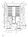
- a fuel cell module 10 has a plurality of fuel cells 11 which are stacked on each other in an axial direction 12 and thus form a cell stack 13.
- the individual fuel cells 11 have a Disc-shaped basic shape with a circular cross-section (see Fig. 2 ) and thus transversely or perpendicular to the axial direction 12, a round outer contour, so that the cell stack 13 has a cylindrical basic shape.
- the fuel cells may also have a different cross-section, such as elliptical, rectangular or square.
- the fuel cells 11 have centrally an inner opening 14 in the axial direction 12 (see Fig. 2 ), so that a cylindrical distribution channel 15 is formed in the cell stack 13, from which each fuel cell 11 natural gas for the taking place in the fuel cell 11 electrochemical reaction can be supplied.
- the cell stack 13 is closed at the top by an upper, first current collector 16.
- the upper current collector 16 has a basic shape identical to the fuel cells 11, but has no inner opening. He thus has the same outer contour as the fuel cell 11.
- the upper current collector 16 forms the anode of the voltage generated by the cell stack 13.
- the upper current collector 16 is applied to a cylindrical cover 34 and is connected to this electrically conductive.
- the cover 34 is by means of two mainly cylindrical clamping elements 35, which only in Fig. 2 are shown braced with a bottom plate 51. At least one of the two clamping elements 35 is electrically conductively connected to the cover 34, so that the necessary electrical contacting of the upper current collector 16 via at least one of the two clamping elements takes place.
- the electrical contacting of the upper current collector can also be done in a different way.
- the cell stack 13 is closed at the bottom by a lower, second current collector 17, which forms the cathode of the voltage generated by the cell stack 13.
- the clamping elements 35 brace it indirectly, the upper and lower current collector 16, 17.
- the lower current collector 17 also has an identical with the fuel cell 11 basic shape and has a circular inner opening 18. He thus has the same outer contour as the fuel cell 11.
- the lower current collector 17 is welded to a hollow cylindrical sleeve 19, which is part of a gas supply 20, to which a gas port 21 is arranged. Process gas can thus be supplied to the distribution channel 15 of the cell stack 13 via the gas connection 21, the gas supply line 20, the sleeve 19 and the inner opening 18 of the lower current collector 17.
- the gas connection 21 and the gas supply line 20 with the sleeve 19 thus form a gas supply system 40 for supplying combustion gas to the cell stack 13.
- a reformer 22 is arranged, in which the methane contained in the supplied natural gas before being fed into the distribution channel 15 in Hydrogen and carbon monoxide and thus converted into process gas.
- the second current collector 17, the sleeve 19, the gas supply line 20 and the gas connection 21 are made of an electrically conductive material in the form of steel, so that the gas connection 21 is electrically conductively connected to the current collector 17.
- the entire gas supply system 40 is made of electrically conductive material.
- the parts of the gas supply system 40 and the lower current collector 17 are welded together, so that the gas supply system 40 and the lower current collector 17 are made in one piece.
- a schematically illustrated power connection 23 is arranged, via which via the gas connection 21 and the gas supply line 20, an electrical connection to the lower current collector 17 can be made.
- the power connection can be designed, for example, as an electrical plug connection. But it is also possible that it has a clamp into which a cable can be clamped by means of a screw.
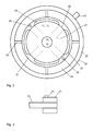
- the necessary for the taking place in the fuel cell 11 electrochemical reaction air is supplied to the cell stack 13 from the outside. This is determined by Fig. 2 explained. Equally distributed on a round outer contour 24 of the cell stack 13 and thus the fuel cell 11 are four identical exhaust gas channels 25 are arranged. Between the exhaust channels 25, gaps 26 result, via which the fuel cells 11 air can be supplied.
- the fuel cells 11 have air guide elements 27 which extend from the gaps 26 in the direction of the distribution channel 15. This allows air, starting from the gaps 26, to flow via the air guiding elements 27 in the direction of the distribution channel 15 and from there back to the outside, wherein the electrochemical reaction with the hydrogen and the carbon monoxide can take place.
- the exhaust gases of the electrochemical reaction, as well as unreacted components reach the exhaust gas channels 25, in which a so-called post-combustion, ie an oxidation of the unreacted hydrogen and carbon monoxide takes place. Via the exhaust gas channels 25, the exhaust gas is discharged in the direction of the lower current collector 17.
- the insulating sheath 28 is made of a ceramic material and has from the outside inwardly leading through holes 29, wherein in the sectional plane of the Fig. 2 four passage openings 29 are arranged. Via the passage openings 29, air can be supplied from an externally formed supply space 30 into an air distribution space 31 formed between cell stack 13 and insulation sheath 28.
- the passage openings 29 are arranged so that they direct the air directly to the exhaust ducts 25. The air then flows mainly in the circumferential direction along the exhaust passages 25 to the gaps 26 described above, and then as described in the direction of the distribution channel 15 to flow.
- the supplied air thus cools the exhaust gas channels 25, which then cool the cell stack 13 by convection.
- the air also flows partially in the axial direction, so as to reach the fuel cell 11, at the axial position not directly a through hole is arranged. Since a pressure loss when flowing into the fuel cells 11 is relatively large, the air is distributed in the axial direction of the distribution space 31 so that all the fuel cells 11 are supplied evenly with air.
- the supply space 30 is bounded by a supply element 32 to the outside.
- the supply element 32 is arranged in a circle around the insulation cover 28 around.
- the supply chamber 30 air is supplied only via an air supply 33. These are the air required for operation and cooling. About the air supply 33 so much air is supplied that forms a quasi-constant pressure in the supply chamber 30.
- the gas port 21 and thus also the power connector 23 is disposed outside of the insulating sleeve 28.
- the gas supply line 20 passes through the insulation sheath 28 and is thus partially disposed inside and partially outside the insulation sheath 28.
- a fuel cell bottom 41 is arranged, which has the same outer contour as the lower current collector 17 and thus also as the cell stack 13 and the upper current collector 16.
- a part of the gas supply system 40 namely a part of the supply line 20 with the sleeve 19 in the fuel cell bottom 41 is arranged.
- the fuel cell bottom 41 has an upper part 42 which adjoins the lower current collector 17 and also has the same outer contour as the lower current collector 17.
- the upper part 42 of the fuel cell bottom 41 consists of several parts, which in the Fig. 1 but are not shown in more detail.
- An outer part 43 of the fuel cell bottom 41 adjoins the upper part 42 of the fuel cell bottom 41 downwardly in the radially outer region.
- the outer part 43 of the fuel cell bottom 41 has a hollow cylindrical basic shape with a substantially same outer contour as the lower current collector 17. Within the outer part 43 of the fuel cell bottom 41 and only later starting as this is an inner part 44 of the fuel cell bottom 41 is arranged. This inner part 44 has a cylindrical basic shape. On its lower side, the inner part 44 has a cylindrical recess 45.
- the fuel cell bottom 41 consists of two different insulation materials.
- the inner part 44 and the upper part 42 are made of a calcium silicate-based ceramic insulating material having a very high strength.
- the outer part 43 is made of an inorganic silica-based insulating material, which has a lower strength and a higher heat insulating effect as compared with the first insulating material.
- the exhaust gas passage 46 is composed of an upper exhaust gas passage part 47 in the upper part 42 of the fuel cell bottom 41 and a lower exhaust gas passage part 48 in the inner part 44 of the fuel cell bottom 41.
- the upper exhaust gas passage member 47 extends first from the outside radially inwards and then directly downwards. It is externally connected to an exhaust gas channel 25, so that the exhaust gas coming from the fuel cells 11 can flow via the exhaust gas channel 25 into the upper exhaust gas passage part 47.
- the other three exhaust passages, not shown, are also each associated with an exhaust passage 25.
- the lower exhaust gas passage part 48 which terminates in the recess 45 of the inner part 44 of the fuel cell bottom 41, adjoins the upper exhaust gas passage part 47 in alignment.
- an exhaust manifold 49 is arranged, which collects the exhaust gases of the four exhaust gas passages 46 and passes through a directly below the fuel cell bottom 41 arranged heat exchanger 50.
- the heat exchanger 50 is thus arranged directly adjacent to the fuel cell bottom 41, wherein the bottom plate 51 is arranged between the fuel cell bottom 41 and the heat exchanger.
- the exhaust gas heat is removed before it is discharged through a fireplace, not shown in the environment.
- the heat exchanger 50 circulates to an unillustrated heat transfer medium, which in turn emit the heat to a space heater or can be used to heat domestic hot water.
Abstract
Description
- Die Erfindung betrifft ein Brennstoffzellenmodul gemäss dem Oberbegriff des Anspruchs 1.
- Brennstoffzellen ermöglichen eine Nutzung von Energie eines Brennstoffs durch Energieumwandlung. Dabei können sowohl elektrische Energie, die aufgrund elektrochemischer Prozesse erzeugt wird, als auch thermische Energie, die in Form von heissen Abgasen der Prozesse anfällt, genutzt werden. Es werden dazu gasförmige Ströme zweier Edukte getrennt durch die Zellen geführt. Das erste Edukt in Form von Umgebungsluft oder kurz Luft, enthält oxidierende Komponenten, das zweite Edukt reduzierende Komponenten. Als zweites Edukt wird insbesondere ein Methan enthaltendes Verbrennungsgas (z. B. Erdgas) verwendet, das vor dem Eintritt in die Zellen durch einen Reformer geführt und dort in die reduzierenden Komponenten Wasserstoff und Kohlenmonoxid und damit in das so genannte Prozessgas umgewandelt wird. Im Folgenden wird das zweite Edukt als Verbrennungsgas oder Erdgas bezeichnet, worunter auch andere geeignete Gase mit reduzierenden Komponenten verstanden werden sollen.
- Ein Brennstoffzellenmodul weist meist mehrere Brennstoffzellen auf, die in einem so genannten Zellenstapel angeordnet sind. Die einzelnen Brennstoffzellen sind dann in einer Axialrichtung gestapelt und werden gemeinsam über ein Gaszuführsystem mit Verbrennungsgas in Form von Erdgas versorgt. An einem ersten axialen Ende des Zellenstapels ist ein erster Stromsammler und an einem zweiten axialen Ende des Zellenstapels ein zweiter Stromsammler angeordnet. Über die beiden Stromsammler kann die von den Brennstoffzellen erzeugte elektrische Energie abgegriffen und abgeleitet werden. Ein derartiges Brennstoffzellenmodul ist beispielsweise in der
EP 1 864 347 B1 beschrieben. - Die
US 2001/046619 A1 beschreibt ebenfalls ein derartiges Brennstoffzellenmodul, bei dem zusätzlich an einem Gaszuführsystem ein Stromanschluss angeordnet ist, der mit dem zweiten Stromsammler elektrisch leitend verbunden ist. - Es ist insbesondere die Aufgabe der Erfindung, ein Brennstoffzellenmodul vorzuschlagen, welches einen einfachen Aufbau ermöglicht. Erfindungsgemäß wird diese Aufgabe mit einem Brennstoffzellenmodul mit den Merkmalen des Anspruchs 1 gelöst.
- Das Brennstoffzellenmodul verfügt über in einem Zellenstapel angeordnete Brennstoffzellen und ein Gaszuführsystem zur Zuführung von Gas zum Betrieb der Brennstoffzellen. Das Gas kann dabei entweder als das Verbrennungsgas, also insbesondere als Erdgas, oder als die oxidierende Komponente, also insbesondere Luft, ausgeführt sein. Im Folgenden wird davon ausgegangen, dass über das genannte Gaszuführsystem das Verbrennungsgas zugeführt. Die Brennstoffzellen sind in einer Axialrichtung gestapelt. An einem ersten axialen Ende des Zellenstapels ist ein erster Stromsammler und an einem zweiten axialen Ende des Zellenstapels ist ein zweiter Stromsammler angeordnet. Über die beiden Stromsammler kann die von den Brennstoffzellen erzeugte elektrische Energie abgegriffen und abgeleitet werden. Das erste und zweite axiale Ende des Zellstapels sind dabei in Axialrichtung gegenüber liegend angeordnet.
- Am Gaszuführsystem ist ein Stromanschluss angeordnet, der mit dem zweiten Stromsammler elektrisch leitend verbunden ist. Über den Stromanschluss kann damit eine elektrische Verbindung zum zweiten Stromsammler hergestellt werden. Es ist für die Ableitung der erzeugten elektrischen Energie damit keine separat zu verlegende elektrische Leitung zum zweiten Stromsammler notwendig, was den Aufbau des Brennstoffzellenmoduls besonders einfach macht. Da beim Betrieb des Brennstoffzellenmoduls in den Brennstoffzellen üblicherweise hohe Temperaturen von mehreren hundert Grad herrschen, ist meist eine Isolation der Brennstoffzellen notwendig. Für eine effektive Isolation und auch für deren einfaches Anbringen ist es vorteilhaft, wenn die Isolation möglichst wenige Öffnungen aufweist. Für das Gaszuführsystem ist auf jeden Fall eine Öffnung notwendig, da das Verbrennungsgas dem Brennstoffzellenmodul von aussen zugeführt werden muss. Da erfindungsgemäss der Stromanschluss für den zweiten Stromsammler am Gaszuführsystem angeordnet ist, ist für die elektrische Verbindung zum zweiten Stromsammler keine zusätzliche Öffnung in der Isolation notwendig.
- Erfindungsgemäss sind der Zellenstapel innerhalb und das Gaszuführsystem teilweise ausserhalb einer Isolationshülle angeordnet. Der am Gaszuführsystem angeordnete Stromanschluss ist ausserhalb der Isolationshülle angeordnet. Das Gaszuführsystem führt damit durch die Isolationshülle hindurch. Vor der Inbetriebnahme des Brennstoffzellenmoduls muss der Stromanschluss des Brennstoffzellenmoduls geeignet elektrisch angeschlossen werden. Dies ist sehr einfach und damit kostengünstig möglich, wenn der Stromanschluss entsprechend der Ausgestaltung der Erfindung ausserhalb der Isolationshülle angeordnet ist.
- Die Brennstoffzellen sind insbesondere als Hochtemperatur-Brennstoffzellen des SOFC-Typs ("Solid Oxid Fuel Cell") ausgeführt. Als Luft wird insbesondere Umgebungsluft verwendet, die auch vor der Zuführung zum Zellenstapel gefiltert werden kann. Im Betriebszustand des Brennstoffzellenmoduls ist die Axialrichtung üblicherweise senkrecht zum Erdboden ausgerichtet. Wenn im Folgenden von "oben" und "unten" die Rede ist, so bezieht sich das auf die beschriebene Ausrichtung des Brennstoffzellenmoduls im Betriebszustand.
- In Ausgestaltung der Erfindung ist das Gaszuführsystem zumindest teilweise aus einem elektrisch leitenden Material ausgeführt. Die elektrisch leitende Verbindung wird dann über das Gaszuführsystem hergestellt. Damit ist keine separate elektrische Leitung beispielsweise in Form eines Kabels zum zweiten Stromsammler notwendig. Das ermöglicht einen besonders einfachen und kostengünstigen Aufbau des Brennstoffzellenmoduls. Ausserdem entfällt die Gefahr, dass bei der Montage das genannte Kabel nicht richtig angeschlossen wird oder es im Betrieb versagt. Damit wird ein zuverlässiger Betrieb des Brennstoffzellenmoduls ermöglicht. Das Gaszufuhrsystem kann auch vollständig oder bis auf Ausnahme von Teilen des Stromanschlusses aus einem elektrisch leitenden Material ausgeführt sein. Das elektrisch leitende Material kann beispielsweise Stahl sein.
- Da das Gaszuführsystem teilweise innerhalb und teilweise ausserhalb der Isolationshülle angeordnet ist, bildet es quasi eine Wärmebrücke durch die Isolation hindurch. Durch die Durchströmung des auch als elektrischer Leiter dienenden Gaszuführsystems durch das Gas von ausserhalb der Isolation nach innerhalb der Isolation ergibt sich eine Kühlung des Gaszuführsystems. Die abgeleitete Wärme wird quasi wieder zurückgeführt. Je massiver das Gaszuführsystem ausgeführt ist, umso mehr wirkt es als Wärmebrücke, auf der anderen Seite führt eine massive Ausführung zu einem geringen elektrischen Widerstand und damit zu geringen elektrischen Verlusten. Durch den beschriebenen Kühleffekt kann das Gaszuführsystem so ausgeführt werden, dass sich ein möglichst geringer elektrischer Widerstand ergibt.
- Insbesondere weist das Gaszuführsystem eine Gaszuführleitung und einen an der Gaszuführleitung angeordneten Gasanschluss auf. Die Gaszuführleitung ist teilweise ausserhalb der Isolationshülle angeordnet. Die Gaszuführleitung ist damit auch zum Teil innerhalb der Isolationshülle angeordnet und führt durch diese hindurch. Der Stromanschluss ist in diesem Fall am ausserhalb der Isolationshülle angeordneten Teil der Gaszuführleitung oder dem Gasanschluss angeordnet. Der Gasanschluss dient dabei zum Anschluss des Gaszuführsystems und damit des Brennstoffzellenmoduls an eine externe Versorgung mit Verbrennungsgas, also beispielsweise an ein öffentliches Erdgasnetz.
- In Ausgestaltung der Erfindung sind der zweite Stromsammler und das Gaszuführsystem einstückig ausgeführt. Der Stromsammler, das Gaszuführsystem und der Stromanschluss bilden damit nur ein einziges Bauteil. Damit weist das Brennstoffzellenmodul nur eine geringe Anzahl an Einzelteilen auf, was eine Montage des Brennstoffzellenmoduls einfach und damit kostengünstig macht. Wenn die elektrische Verbindung zwischen Stromanschluss und zweitem Stromsammler hergestellt wird, führt die einstückige Ausführung auch zu einer besonders sicheren elektrischen Verbindung, da eine ungewollte Unterbrechung der elektrisch leitenden Verbindung quasi nicht möglich ist. Damit wird ein besonders zuverlässiger Betrieb des Brennstoffzellenmoduls ermöglicht. Die einstückige Ausführung des Gaszuführsystems kann beispielsweise durch Verschweissen oder Verlöten der einzelnen Bauteile wie Stromsammler, Gaszuführleitung und Gasanschluss erreicht werden. Die genannten Bauteile können ebenfalls aus einzelnen Teilen bestehen, die beispielsweise verschweisst oder verlötet werden.
- In Ausgestaltung der Erfindung ist innerhalb des Gaszuführsystems ein Reformer angeordnet. Der Reformer dient dazu, das im Verbrennungsgas enthaltene Methan in die reduzierenden Komponenten Wasserstoff und Kohlenmonoxid umzuwandeln. Damit wird ermöglicht, dass der Reformer platzsparend untergebracht werden kann und ausserdem kann er im Zuge einer Vormontage in das Gaszuführsystem eingesetzt werden, was eine einfache und kostengünstige Montage des Brennstoffzellenmoduls ermöglicht. Der Reformer ist insbesondere in der Gaszuführleitung angeordnet, die dazu über eine spezielle Hülse verfügen kann. Der Reformer wird dabei nicht als Teil des Gaszuführsystems angesehen.
- In Ausgestaltung der Erfindung weist der zweite Stromsammler und insbesondere auch der erste Stromsammler die gleiche Aussenkontur wie die Brennstoffzellen auf. Damit werden ein effektiver Betrieb und gleichzeitig ein kompakter Aufbau des Brennstoffzellenmoduls ermöglicht. Die Brennstoffzellen und damit auch die Stromsammler weisen insbesondere einen kreisrunden Querschnitt quer zur Axialrichtung auf. Sie können aber auch einen anderen Querschnitt, wie beispielsweise ellipsenförmig, rechteckig oder quadratisch aufweisen. Unter der Aussenkontur soll hier die Kontur in einer Ebene senkrecht zur Axialrichtung verstanden werden.
- In Ausgestaltung der Erfindung weist das Brennstoffzellenmodul ein Spannelement auf, mittels welchem der erste und zweite Stromsammler und damit der Zellenstapel zumindest mittelbar verspannt werden können. Das Spannelement ist mit dem ersten Stromsammler elektrisch leitend verbunden, so dass die notwendige elektrische Kontaktierung des ersten Stromsammlers über das Spannelement erfolgen kann. Damit kann ein besonders einfacher und kostengünstiger Aufbau des Brennstoffzellenmoduls ermöglicht werden.
- Eine Verspannung des Zellstapels ist beispielsweise in der
EP 1 864 347 B1 beschrieben. - Das Spannelement kann mit dem ersten Stromsammler direkt oder indirekt über einen Deckel oder ein so genanntes Spannjoch verbunden sein.
- Die beschriebene Kontaktierung des ersten Stromsammlers ist dabei auch unabhängig von der Anordnung eines Stromanschlusses am Gaszuführsystem gemäss Anspruch 1 umsetzbar.
- In Ausgestaltung der Erfindung ist das Gaszuführsystem zumindest teilweise in einem Brennstoffzellenboden angeordnet, der aus einem Isolationsmaterial ausgeführt ist. Damit wird auch eine Isolation des Zellenstapels im Bereich des Gaszuführsystems erreicht. Das Gaszuführsystem ist insbesondere so ausgeführt, dass die Gaszuführleitung auf der den Brennstoffzellen abgewandten Seite in Axialrichtung zum zweiten Stromsammler führt. Damit ist der Brennstoffzellenboden ebenfalls an auf der den Brennstoffzellen abgewandten Seite des zweiten Stromsammlers angeordnet und sorgt für eine Isolierung des Zellenstapels in Axialrichtung. Ausserdem ist der Brennstoffzellenboden im Betriebszustand des Brennstoffzellenmoduls meist unterhalb des Zellenstapels angeordnet und dient damit zu dessen sicherer Abstützung und quasi als Boden des gesamten Brennstoffzellenmoduls.
- In Ausgestaltung der Erfindung weist der Brennstoffzellenboden die gleiche Aussenkontur wie die Brennstoffzellen auf. Damit ist ein besonders kompakter Aufbau des Brennstoffzellenmoduls möglich.
- In Ausgestaltung der Erfindung ist der Brennstoffzellenboden aus zwei verschiedenen Isolationsmaterialen ausgeführt. Insbesondere weist der Brennstoffzellenboden einen inneren Teil aus einem ersten Isolationsmaterial und einen äusseren Teil aus einem zweiten Isolationsmaterial auf. Es ist dabei nicht erforderlich, dass der Brennstoffzellenboden über seine gesamte Ausdehnung in Axialrichtung aus zwei verschiedenen Isolationsmaterialien ausgeführt ist. Der Brennstoffzellenboden kann auch aus mehr als zwei verschiedenen Isolationsmaterialen bestehen.
- Das erste Isolationsmaterial verfügt insbesondere über eine höhere Festigkeit und/oder eine geringere Wärmeisolationswirkung als das zweite Isolationsmaterial. Damit können die Isolationswirkung und die Stützwirkung des Brennstoffzellenbodens besonders gut an die gegebenen Erfordernisse angepasst werden. Es ist so möglich, den Brennstoffzellenboden innen hoch mechanisch belastbar und aussen besonders gut wärmeisolierend auszuführen. Das erste Isolationsmaterial kann beispielsweise als ein keramisches Isolationsmaterial auf Calcium- und/oder Magnesium- und/oder Aluminiumsilicatbasis bestehen und zusätzlich Eisen- und/oder Titan- und/oder Kalium- und/oder Natriumoxid enthalten. Das zweite Isolationsmaterial kann beispielsweise als ein anorganisches Material auf Basis von Kieselsäure mit Infrarot-Trübungsmitteln ausgeführt sein. Derartige Isolationsmaterialien sind im Handel problemlos erhältlich.
- In Ausgestaltung der Erfindung weist der Brennstoffzellenboden zumindest einen Abgasdurchlass auf, der insbesondere zumindest teilweise im inneren Teil des Brennstoffzellenbodens angeordnet ist. Bei der elektrochemischen Reaktion in den Brennstoffzellen und der so genannten Nachverbrennung entsteht heisses Abgas, das abgeleitet und insbesondere zu einem Kamin geführt werden muss. Die Anordnung eines Abgasdurchlasses im Brennstoffzellenboden ermöglicht einen besonders kompakten Aufbau des Brennstoffzellenmoduls. Ausserdem wird damit auch eine Isolation des Abgases gegenüber den anderen Bauteilen des Brennstoffzellenmoduls erreicht. Der Brennstoffzellenboden weist insbesondere mehrere und im speziellen vier Abgasdurchlässe auf.
- In Ausgestaltung der Erfindung weist das Brennstoffzellenmodul einen Wärmetauscher auf, welcher unmittelbar benachbart zum Brennstoffzellenboden und insbesondere unterhalb des Brennstoffzellenbodens angeordnet ist. In diesem Wärmetauscher wird dem Abgas die Wärmeenergie entzogen und beispielsweise dem Wasser eines Heizkreises zugeführt. Der Wärmetauscher wirkt damit als Wärmesenke für das Brennstoffzellenmodul. Das Gaszuführsystem und damit auch der am Gaszuführsystem angeordnete Stromanschluss sind damit zumindest mittelbar mit dem Wärmetauscher wärmeableitend verbunden. Damit wird ermöglicht, dass der Stromanschluss auch im Betrieb des Brennstoffzellenmoduls keine zu hohe Temperatur, beispielsweise immer maximal 100 °C aufweist und so keine speziellen, für sehr hohe Temperaturen geeignete elektrischen Anschlusselemente, beispielsweise Steckverbindungen verwendet werden müssen. Dies ermöglicht einen kostengünstigen Aufbau des Stromanschlusses und damit des Brennstoffzellenmoduls.
- Weitere Vorteile, Merkmale und Einzelheiten der Erfindung ergeben sich anhand der nachfolgenden Beschreibung von Ausführungsbeispielen sowie anhand der Zeichnungen, in welchen gleiche oder funktionsgleiche Elemente mit identischen Bezugszeichen versehen sind.
- Dabei zeigen:
- Fig. 1
- ein Brennstoffzellenmodul in einem Längsschnitt,
- Fig. 2
- das Brennstofifzellenmodul in einem Querschnitt und
- Fig. 3
- einen Gasanschluss des Brennstoffzellenmoduls
- Gemäss
Fig. 1 weist ein Brennstoffzellenmodul 10 mehrere Brennstoffzellen 11 auf, die in einer Axialrichtung 12 aufeinander gestapelt sind und so einen Zellenstapel 13 bilden. Die einzelnen Brennstoffzellen 11 weisen eine scheibenförmige Grundform mit einem kreisrunden Querschnitt (sieheFig. 2 ) und damit quer bzw. senkrecht zur Axialrichtung 12 eine runde Aussenkontur auf, so dass der Zellenstapel 13 eine zylinderförmige Grundform aufweist. Die Brennstoffzellen können aber auch einen anderen Querschnitt, wie beispielsweise ellipsenförmig, rechteckig oder quadratisch aufweisen. - Die Brennstoffzellen 11 weisen mittig eine Innenöffnung 14 in Axialrichtung 12 auf (siehe
Fig. 2 ), so dass sich im Zellenstapel 13 ein zylinderförmiger Verteilkanal 15 ausbildet, von dem aus jeder Brennstoffzelle 11 Erdgas für die in den Brennstoffzellen 11 stattfindende elektrochemische Reaktion zugeführt werden kann. - Der Zellenstapel 13 wird nach oben von einem oberen, ersten Stromsammler 16 abgeschlossen. Der obere Stromsammler 16 hat eine mit den Brennstoffzellen 11 identische Grundform, weist aber keine Innenöffnung auf. Er hat damit die gleiche Aussenkontur wie die Brennstoffzellen 11. Der obere Stromsammler 16 bildet die Anode der vom Zellenstapel 13 erzeugten Spannung. Der obere Stromsammler 16 liegt an einem zylinderförmigen Deckel 34 an und ist mit diesem elektrisch leitend verbunden. Der Deckel 34 wird mittels zweier hauptsächlich zylinderförmigen Spannelemente 35, die nur in
Fig. 2 dargestellt sind, mit einer Bodenplatte 51 verspannt. Die Spannelemente 35 verlaufen dazu entlang dem Zellenstapel 13. Zumindest eines der beiden Spannelemente 35 ist elektrisch leitend mit dem Deckel 34 verbunden, so dass die notwendige elektrische Kontaktierung des oberen Stromsammlers 16 über zumindest eines der beiden Spannelemente erfolgt. - Statt mittels eines zylinderförmigen Deckels kann die Verspannung und damit die beschriebene Kontaktierung mittels eines hauptsächlich quaderförmigen Jochs erfolgen.
- Die elektrische Kontaktierung des oberen Stromsammlers kann aber auch auf eine andere Weise erfolgen.
- Der Zellenstapel 13 wird nach unten von einem unteren, zweiten Stromsammler 17 abgeschlossen, der die Kathode der vom Zellenstapel 13 erzeugten Spannung bildet. Die Spannelemente 35 verspannen damit mittelbar auch den oberen und unteren Stromsammler 16, 17. Der untere Stromsammler 17 hat ebenfalls eine mit den Brennstoffzellen 11 identische Grundform und weist eine kreisrunde Innenöffnung 18 auf. Er hat damit die gleiche Aussenkontur wie die Brennstoffzellen 11. Der untere Stromsammler 17 ist mit einer hohlzylinderförmigen Hülse 19 verschweisst, welche Teil einer Gaszuführleitung 20 ist, an der ein Gasanschluss 21 angeordnet ist. Über den Gasanschluss 21, die Gaszuführleitung 20, die Hülse 19 und die Innenöffnung 18 des unteren Stromsammlers 17 kann damit Prozessgas dem Verteilkanal 15 des Zellenstapels 13 zugeführt werden. Der Gasanschluss 21 und die Gaszuführleitung 20 mit der Hülse 19 bilden damit ein Gaszuführsystem 40 zur Zuführung von Verbrennungsgas zum Zellenstapel 13. In der Hülse 19 ist ein Reformer 22 angeordnet, in dem das im zugeführten Erdgas enthaltene Methan vor der Zuführung in den Verteilkanal 15 in Wasserstoff und Kohlenmonoxid und damit in Prozessgas umgewandelt wird. Der zweite Stromsammler 17, die Hülse 19, die Gaszuführleitung 20 und der Gasanschluss 21 sind aus einem elektrisch leitenden Material in Form von Stahl ausgeführt, so dass der Gasanschluss 21 mit dem Stromsammler 17 elektrisch leitend verbunden ist. Damit ist das gesamte Gaszuführsystem 40 aus elektrisch leitendem Material ausgeführt. Die Einzelteile des Gaszuführsystems 40 und der untere Stromsammler 17 sind untereinander verschweisst, so dass das Gaszuführsystem 40 und der untere Stromsammler 17 einstückig ausgeführt sind.
- Am Gasanschluss 21 ist gemäss
Fig. 3 ein schematisch dargestellter Stromanschluss 23 angeordnet, über welchen über den Gasanschluss 21 und die Gaszuführleitung 20 eine elektrische Verbindung zum unteren Stromsammler 17 hergestellt werden kann. Der Stromanschluss kann beispielsweise als eine elektrische Steckverbindung ausgeführt sein. Es ist aber ebenfalls möglich, dass er eine Klemme aufweist, in die ein Kabel mittels einer Schraube festgeklemmt werden kann. - Die für die in den Brennstoffzellen 11 stattfindende elektrochemische Reaktion notwenige Luft wird dem Zellenstapel 13 von aussen zugeführt. Dies wird anhand von
Fig. 2 erläutert. Gleichmässig an einer runden Aussenkontur 24 des Zellenstapels 13 und damit der Brennstoffzellen 11 verteilt sind vier identische Abgaskanäle 25 angeordnet. Zwischen den Abgaskanälen 25 ergeben sich Lücken 26, über die den Brennstoffzellen 11 Luft zugeführt werden kann. Die Brennstoffzellen 11 verfügen über Luftleitelemente 27, die von den Lücken 26 in Richtung Verteilkanal 15 verlaufen. Damit kann Luft ausgehend von den Lücken 26 über die Luftleitelemente 27 in Richtung Verteilkanal 15 strömen und von dort wieder nach aussen, wobei die elektrochemische Reaktion mit dem Wasserstoff und dem Kohlenmonoxid stattfinden kann. Die Abgase der elektrochemischen Reaktion, sowie noch nicht reagierte Bestandteile gelangen in die Abgaskanäle 25, in denen auch eine so genannte Nachverbrennung, also eine Oxidation des nicht reagierten Wasserstoffs und des Kohlenmonoxids stattfindet. Über die Abgaskanäle 25 wird das Abgas in Richtung unterem Stromsammler 17 abgeleitet. - Um den Zellenstapel 13 herum ist eine hohlzylinderförmige Isolationshülle 28 angeordnet, so dass der Zellenstapel 13 innerhalb der Isolationshülle 28 angeordnet ist. Die Isolationshülle 28 ist aus einem keramischen Material ausgeführt und weist von aussen nach innen führende Durchgangsöffnungen 29 auf, wobei in der Schnittebene der
Fig. 2 vier Durchgangsöffnungen 29 angeordnet sind. Über die Durchgangsöffnungen 29 kann Luft aus einem aussen ausgebildeten Versorgungsraum 30 in einen zwischen Zellenstapel 13 und Isolationshülle 28 ausgebildeten Luftverteilraum 31 zugeführt werden. Die Durchgangsöffnungen 29 sind dabei so angeordnet, dass sie die Luft direkt auf die Abgaskanäle 25 leiten. Die Luft strömt dann hauptsächlich in Umfangsrichtung an den Abgaskanälen 25 entlang zu den oben beschriebenen Lücken 26, um dann wie beschrieben in Richtung Verteilkanal 15 zu strömen. Die zugeführte Luft kühlt damit die Abgaskanäle 25, welche dann über Konvektion den Zellenstapel 13 kühlen. Die Luft strömt auch teilweise in Axialrichtung, um so auch zu den Brennstoffzellen 11 zu gelangen, an deren Axialposition nicht direkt eine Durchgangsöffnung angeordnet ist. Da ein Druckverlust beim Strömen in die Brennstoffzellen 11 hinein vergleichsweise gross ist, verteilt sich die Luft in axialer Richtung des Verteilraums 31 so, dass alle Brennstoffzellen 11 gleichmässig mit Luft versorgt werden. - Der Versorgungsraum 30 wird von einem Versorgungselement 32 nach aussen begrenzt. Das Versorgungselement 32 ist kreisförmig um die Isolationshülle 28 herum angeordnet. Dem Versorgungsraum 30 wird nur über eine Luftzuführung 33 Luft zugeführt. Dabei handelt es sich um die für den Betrieb und die Kühlung notwendige Luft. Über die Luftzuführung 33 wird so viel Luft zugeführt, dass sich im Versorgungsraum 30 ein quasi konstanter Druck ausbildet.
- Wie in
Fig. 1 dargestellt, ist der Gasanschluss 21 und damit auch der Stromanschluss 23 ausserhalb der Isolationshülle 28 angeordnet. Die Gaszuführleitung 20 führt durch die Isolationshülle 28 hindurch und ist damit teilweise innerhalb und teilweise ausserhalb der Isolationshülle 28 angeordnet. - Unterhalb des unteren Stromsammlers 17 ist ein Brennstoffzellenboden 41 angeordnet, der die selbe Aussenkontur wie der untere Stromsammler 17 und damit auch wie der Zellenstapel 13 und der obere Stromsammler 16 aufweist. Damit ist auch ein Teil des Gaszuführsystems 40, nämlich ein Teil der Zuführleitung 20 mit der Hülse 19 im Brennstoffzellenboden 41 angeordnet. Der Brennstoffzellenboden 41 weist einen oberen Teil 42 auf, der an den unteren Stromsammler 17 angrenzt und auch die selbe Aussenkontur wie der untere Stromsammler 17 aufweist. Der obere Teil 42 des Brennstoffzellenbodens 41 besteht aus mehreren Teilen, die in der
Fig. 1 aber nicht genauer dargestellt sind. An den oberen Teil 42 des Brennstoffzellenbodens 41 schliesst sich nach unten im radial äusseren Bereich ein äusserer Teil 43 des Brennstoffzellenbodens 41 an. Der äussere Teil 43 des Brennstoffzellenbodens 41 weist eine hohlzylinderförmige Grundform mit einer im Wesentlichen gleichen Aussenkontur wie der untere Stromsammler 17 auf. Innerhalb des äusseren Teils 43 des Brennstoffzellenbodens 41 und erst weiter unten als dieser beginnend ist ein innerer Teil 44 des Brennstoffzellenbodens 41 angeordnet. Dieser innere Teil 44 weist eine zylinderförmige Grundform auf. An seiner unteren Seite weist der innere Teil 44 eine zylinderförmige Ausnehmung 45 auf. - Der Brennstoffzellenboden 41 besteht aus zwei unterschiedlichen Isolationsmaterialien. Der innere Teil 44 und der obere Teil 42 bestehen aus einem keramischen Isolationsmaterial auf Calciumsilicatbasis, das über eine sehr hohe Festigkeit verfügt. Der äussere Teil 43 besteht aus einem anorganischen Isolationsmaterial auf Kieselsäurebasis, das im Vergleich zum ersten Isolationsmaterial über eine geringere Festigkeit und eine höhere Wärmeisolationswirkung verfügt.
- Zur Ableitung des Abgases der Brennstoffzellen 11 sind im Brennstoffzellenboden 41 insgesamt vier Abgasdurchlässe 46 vorgesehen, von denen in der
Fig. 1 aus Übersichtlichkeitsgründen nur einer dargestellt ist. Der Abgasdurchlass 46 setzt sich aus einem oberen Abgasdurchlassteil 47 im oberen Teil 42 des Brennstoffzellenbodens 41 und einem unteren Abgasdurchlassteil 48 im inneren Teil 44 des Brennstoffzellenbodens 41 zusammen. Der obere Abgasdurchlassteil 47 verläuft zunächst von aussen radial nach innen und anschliessend direkt nach unten. Er ist aussen mit einem Abgaskanal 25 verbunden, so dass das von den Brennstoffzellen 11 kommende Abgas über den Abgaskanal 25 in den oberen Abgasdurchlassteil 47 strömen kann. Die anderen drei nicht dargestellten Abgasdurchlässe sind ebenfalls jeweils einem Abgaskanal 25 zugeordnet. An den oberen Abgasdurchlassteil 47 schliesst sich fluchtend der untere Abgasdurchlassteil 48 an, der in der Ausnehmung 45 des inneren Teils 44 des Brennstoffzellenbodens 41 endet. In der Ausnehmung 45 ist ein Abgassammler 49 angeordnet, der die Abgase der vier Abgasdurchlässe 46 sammelt und durch einen direkt unterhalb des Brennstoffzellenbodens 41 angeordneten Wärmetauscher 50 hindurchleitet. Der Wärmetauscher 50 ist damit unmittelbar benachbart zum Brennstoffzellenboden 41 angeordnet, wobei zwischen dem Brennstoffzellenboden 41 und dem Wärmetauscher die Bodenplatte 51 angeordnet ist. - Im Wärmetauscher 50 wird dem Abgas Wärme entzogen, bevor es über einen nicht dargestellten Kamin in die Umwelt abgeführt wird. Im Wärmetauscher 50 zirkuliert dazu ein nicht dargestelltes Wärmeträgermedium, das wiederum die Wärme an eine Raumheizung abgeben oder zur Erwärmung von Brauchwasser genutzt werden kann.
Claims (14)
- Brennstoffzellenmodul mit- in einem Zellenstapel (13) angeordneten Brennstoffzellen (11) und- einem Gaszuführsystem (40) zur Zuführung von Gas zum Betrieb der Brennstoffzellen (11),
wobei- die Brennstoffzellen (11) in einer Axialrichtung (12) gestapelt sind und- an einem ersten axialen Ende des Zellenstapels (13) ein erster Stromsammler (16) und an einem zweiten axialen Ende des Zellenstapels (13) ein zweiter Stromsammler(17) angeordnet ist,
wobei
am Gaszuführsystem (40) ein Stromanschluss (23) angeordnet ist, der mit dem zweiten Stromsammler (17) elektrisch leitend verbunden ist dadurch gekennzeichnet, dass
der Zellenstapel (13) innerhalb und das Gaszuführsystem (40) teilweise ausserhalb einer Isolationshülle (28) angeordnet sind und der Stromanschluss (23) ausserhalb der Isolationshülle (28) angeordnet ist.. - Brennstoffzellenmodul nach Anspruch 1,
dadurch gekennzeichnet, dass
das Gaszuführsystem (40) zumindest teilweise aus einem elektrisch leitenden Material ausgeführt ist und die elektrisch leitende Verbindung über das Gaszuführsystem (40) hergestellt ist. - Brennstoffzellenmodul nach Anspruch 1 oder 2,
dadurch gekennzeichnet, dass
das Gaszuführsystem (40) eine Gaszuführleitung (20) und einen an der Gaszuführleitung (20) angeordneten Gasanschluss (21) aufweist, wobei die Gaszuführleitung (20) teilweise ausserhalb der Isolationshülle (28) angeordnet ist und der Stromanschluss (23) an der Gaszuführleitung (20) oder dem Gasanschluss (21) angeordnet ist. - Brennstoffzellenmodul nach einem der Ansprüche 1 bis 3,
dadurch gekennzeichnet, dass
der zweite Stromsammler (17) und das Gaszuführsystem (40) einstückig ausgeführt sind. - Brennstoffzellenmodul nach einem der Ansprüche 1 bis 4,
dadurch gekennzeichnet, dass
innerhalb des Gaszuführsystems (40) ein Reformer (22) angeordnet ist. - Brennstoffzellenmodul nach einem der Ansprüche 1 bis 5,
dadurch gekennzeichnet, dass
der zweite Stromsammler (17) und insbesondere auch der erste Stromsammler (16) die gleiche Aussenkontur wie die Brennstoffzellen (11) aufweisen. - Brennstoffzellenmodul nach einem der Ansprüche 1 bis 6,
gekennzeichnet durch
ein Spannelement (35), mittels welchem der erste und zweite Stromsammler (16, 17) zumindest mittelbar verspannt werden, und welches mit dem ersten Stromsammler (16) elektrisch leitend verbunden ist. - Brennstoffzellenmodul nach einem der Ansprüche 1 bis 7,
dadurch gekennzeichnet, dass
das Gaszuführsystem (40) zumindest teilweise in einem Brennstoffzellenboden (41) angeordnet ist, der aus einem Isolationsmaterial ausgeführt ist. - Brennstoffzellenmodul nach Anspruch 8,
dadurch gekennzeichnet, dass
der Brennstoffzellenboden (41) die gleiche Aussenkontur wie die Brennstoffzellen (11) aufweist. - Brennstoffzellenmodul nach Anspruch 8 oder 9,
dadurch gekennzeichnet, dass
der Brennstoffzellenboden (41) aus zwei verschiedenen Isolationsmaterialen ausgeführt ist. - Brennstoffzellenmodul nach Anspruch 10,
dadurch gekennzeichnet, dass
der Brennstoffzellenboden (41) einen inneren Teil (44) aus einem ersten Isolationsmaterial und einen äusseren Teil (43) aus einem zweiten Isolationsmaterial aufweist und das erste Isolationsmaterial eine höhere Festigkeit und/oder eine geringere Wärmeisolationswirkung als das zweite Isolationsmaterial aufweist. - Brennstoffzellenmodul nach einem der Ansprüche 8 bis 11,
dadurch gekennzeichnet, dass
der Brennstoffzellenboden (41) zumindest einen Abgasdurchlass (46) aufweist. - Brennstoffzellenmodul nach Anspruch 11 und 12,
dadurch gekennzeichnet, dass
der Abgasdurchlass (46) zumindest teilweise im inneren Teil (44) des Brennstoffzellenbodens (41) ausgeführt ist. - Brennstoffzellenmodul nach einem der Ansprüche 8 bis 13,
gekennzeichnet durch
einen Wärmetauscher (50), welcher unmittelbar benachbart zum Brennstoffzellenboden (41) angeordnet ist.
Priority Applications (1)
| Application Number | Priority Date | Filing Date | Title |
|---|---|---|---|
| EP15190345.7A EP3035430B1 (de) | 2014-12-19 | 2015-10-19 | Brennstoffzellenmodul |
Applications Claiming Priority (2)
| Application Number | Priority Date | Filing Date | Title |
|---|---|---|---|
| EP14199229 | 2014-12-19 | ||
| EP15190345.7A EP3035430B1 (de) | 2014-12-19 | 2015-10-19 | Brennstoffzellenmodul |
Publications (2)
| Publication Number | Publication Date |
|---|---|
| EP3035430A1 true EP3035430A1 (de) | 2016-06-22 |
| EP3035430B1 EP3035430B1 (de) | 2019-09-25 |
Family
ID=52344964
Family Applications (1)
| Application Number | Title | Priority Date | Filing Date |
|---|---|---|---|
| EP15190345.7A Not-in-force EP3035430B1 (de) | 2014-12-19 | 2015-10-19 | Brennstoffzellenmodul |
Country Status (3)
| Country | Link |
|---|---|
| US (1) | US11349142B2 (de) |
| EP (1) | EP3035430B1 (de) |
| JP (1) | JP6663694B2 (de) |
Cited By (2)
| Publication number | Priority date | Publication date | Assignee | Title |
|---|---|---|---|---|
| WO2019081866A1 (fr) * | 2017-10-26 | 2019-05-02 | Commissariat A L'energie Atomique Et Aux Energies Alternatives | Ensemble d'un empilement à oxydes solides de type soec/sofc et d'un système de serrage avec système de surchauffe des gaz intégré |
| DE102020128312A1 (de) | 2020-10-28 | 2022-04-28 | Audi Aktiengesellschaft | Brennstoffzellenstapel, Brennstoffzellenvorrichtung sowie Kraftfahrzeug mit einer Brennstoffzellenvorrichtung |
Families Citing this family (1)
| Publication number | Priority date | Publication date | Assignee | Title |
|---|---|---|---|---|
| KR102587080B1 (ko) * | 2017-12-14 | 2023-10-10 | 현대자동차주식회사 | 연료전지 스택 |
Citations (4)
| Publication number | Priority date | Publication date | Assignee | Title |
|---|---|---|---|---|
| EP1037296A1 (de) * | 1999-03-17 | 2000-09-20 | Sulzer Hexis AG | Brennstoffzellenbatterie mit Nachverbrennung an der Peripherie eines Zellenstapels |
| US20010046619A1 (en) | 2000-03-17 | 2001-11-29 | Allen Jeffrey P. | Fuel cell stack assembly |
| EP1864347B1 (de) | 2005-03-21 | 2009-11-25 | Sulzer Hexis AG | Anlage mit hochtemperatur-brennstoffzellen und einer multikomponenten-hülle zu einem zellenstappel |
| US20110262819A1 (en) * | 2010-04-23 | 2011-10-27 | Crumm Aaron T | Solid oxide fuel cell module with current collector |
Family Cites Families (15)
| Publication number | Priority date | Publication date | Assignee | Title |
|---|---|---|---|---|
| US4476197A (en) * | 1983-10-12 | 1984-10-09 | The United States Of America As Represented By The United States Department Of Energy | Integral manifolding structure for fuel cell core having parallel gas flow |
| US5501200A (en) * | 1994-06-28 | 1996-03-26 | Bogartz; Stuart P. | Compressed gas fueling system |
| ATE233953T1 (de) * | 1996-06-19 | 2003-03-15 | Sulzer Hexis Ag | Verfahren zum betreiben einer vorrichtung mit brennstoffzellen |
| JP2003109650A (ja) | 2001-09-28 | 2003-04-11 | Mitsubishi Materials Corp | 燃料電池の集電部構造 |
| WO2003088395A1 (fr) * | 2002-04-17 | 2003-10-23 | Matsushita Electric Industrial Co., Ltd. | Pile a combustible a electrolyte polymerique |
| JP4585218B2 (ja) | 2003-03-28 | 2010-11-24 | 京セラ株式会社 | 燃料電池組立体 |
| US20060093890A1 (en) * | 2004-10-29 | 2006-05-04 | Steinbroner Matthew P | Fuel cell stack compression systems, and fuel cell stacks and fuel cell systems incorporating the same |
| JP4598509B2 (ja) | 2004-12-22 | 2010-12-15 | 本田技研工業株式会社 | 燃料電池システム |
| JP4407681B2 (ja) | 2006-09-27 | 2010-02-03 | カシオ計算機株式会社 | 燃料電池装置及びこれを備える電子機器 |
| JP2008084809A (ja) * | 2006-08-29 | 2008-04-10 | Yamaha Motor Co Ltd | 水素供給用配管の接続構造 |
| JP5066927B2 (ja) | 2007-02-08 | 2012-11-07 | カシオ計算機株式会社 | 燃料電池装置及び電子機器 |
| WO2009119616A1 (ja) * | 2008-03-26 | 2009-10-01 | 京セラ株式会社 | 改質器、セルスタック装置および燃料電池モジュールならびに燃料電池装置 |
| JP2009277374A (ja) | 2008-05-12 | 2009-11-26 | Ngk Spark Plug Co Ltd | 固体酸化物形燃料電池 |
| DE102011013618A1 (de) * | 2011-03-11 | 2012-09-13 | Li-Tec Battery Gmbh | Energiespeichervorrichtung |
| EP2786442B1 (de) * | 2011-11-30 | 2016-10-19 | Alan Devoe | Brennstoffzellenelement |
-
2015
- 2015-10-19 EP EP15190345.7A patent/EP3035430B1/de not_active Not-in-force
- 2015-12-04 US US14/959,254 patent/US11349142B2/en active Active
- 2015-12-04 JP JP2015237077A patent/JP6663694B2/ja not_active Expired - Fee Related
Patent Citations (4)
| Publication number | Priority date | Publication date | Assignee | Title |
|---|---|---|---|---|
| EP1037296A1 (de) * | 1999-03-17 | 2000-09-20 | Sulzer Hexis AG | Brennstoffzellenbatterie mit Nachverbrennung an der Peripherie eines Zellenstapels |
| US20010046619A1 (en) | 2000-03-17 | 2001-11-29 | Allen Jeffrey P. | Fuel cell stack assembly |
| EP1864347B1 (de) | 2005-03-21 | 2009-11-25 | Sulzer Hexis AG | Anlage mit hochtemperatur-brennstoffzellen und einer multikomponenten-hülle zu einem zellenstappel |
| US20110262819A1 (en) * | 2010-04-23 | 2011-10-27 | Crumm Aaron T | Solid oxide fuel cell module with current collector |
Cited By (5)
| Publication number | Priority date | Publication date | Assignee | Title |
|---|---|---|---|---|
| WO2019081866A1 (fr) * | 2017-10-26 | 2019-05-02 | Commissariat A L'energie Atomique Et Aux Energies Alternatives | Ensemble d'un empilement à oxydes solides de type soec/sofc et d'un système de serrage avec système de surchauffe des gaz intégré |
| FR3073093A1 (fr) * | 2017-10-26 | 2019-05-03 | Commissariat A L'energie Atomique Et Aux Energies Alternatives | Ensemble d'un empilement a oxydes solides de type soec/sofc et d'un systeme de serrage avec systeme de surchauffe des gaz integre |
| US11335934B2 (en) | 2017-10-26 | 2022-05-17 | Commissariat A L'energie Atomique Et Aux Energies Alternatives | Assembly comprising a SOEC/SOFC-type solid oxide stack and a clamping system with an integrated gas superheating system |
| DE102020128312A1 (de) | 2020-10-28 | 2022-04-28 | Audi Aktiengesellschaft | Brennstoffzellenstapel, Brennstoffzellenvorrichtung sowie Kraftfahrzeug mit einer Brennstoffzellenvorrichtung |
| WO2022089787A1 (de) | 2020-10-28 | 2022-05-05 | Audi Ag | Brennstoffzellenstapel, brennstoffzellenvorrichtung sowie kraftfahrzeug mit einer brennstoffzellenvorrichtung |
Also Published As
| Publication number | Publication date |
|---|---|
| US11349142B2 (en) | 2022-05-31 |
| US20160181649A1 (en) | 2016-06-23 |
| JP6663694B2 (ja) | 2020-03-13 |
| EP3035430B1 (de) | 2019-09-25 |
| JP2016119297A (ja) | 2016-06-30 |
Similar Documents
| Publication | Publication Date | Title |
|---|---|---|
| DE69910624T2 (de) | Brennstoffzellenaufbau mit interner reformierung und vereinfachter brennstoffzuführung | |
| DE102007002286B4 (de) | Brennstoffzellensystem und Verfahren zu dessen Herstellung | |
| DE102016203792B4 (de) | Brennstoffzellenmodul | |
| EP3035430B1 (de) | Brennstoffzellenmodul | |
| AT521065B1 (de) | Brennstoffzellensystem und Verfahren zum Aufheizen eines Brennstoffzellensystems | |
| DE102016206157B4 (de) | Brennstoffzellenmodul | |
| DE102016200443B4 (de) | Brennstoffzellenmodul | |
| EP1861890A1 (de) | Anlage mit hochtemperatur-brennstoffzellen und spanneinrichtung für einen zellenstapel | |
| DE19935719C2 (de) | Kühlsystem für Brennstoffzellen | |
| DE102008043873B4 (de) | Strömungsfeldplatte für eine Brennstoffzelle | |
| EP1617499B1 (de) | Brennstoffzellensystem | |
| DE19606665A1 (de) | Anlage zur Erzeugung elektrischer Energie mit Festoxidbrennstoffzellen | |
| EP1776728B1 (de) | Brennstoffzellen-system | |
| WO2018104081A1 (de) | Wärmeübertragungsvorrichtung | |
| EP3035431B1 (de) | Brennstoffzellenmodul und verfahren zum betrieb eines brennstoffzellenmoduls | |
| DE102017215479A1 (de) | Brennstoffzellenstapel mit integrierter Endplattentemperierung sowie Brennstoffzellensystem und Fahrzeug mit einem solchen | |
| AT523315B1 (de) | Brennstoffzellensystem und Verfahren zum Betreiben eines Brennstoffzellensystems | |
| DE102009037145B4 (de) | Hochtemperaturbrennstoffzellensystem mit einem Startbrenner | |
| DE102013013723B4 (de) | Vorrichtung zur Verspannung eines Brennstoffzellen-Stapels zur Strom- und/oder Wärmeerzeugung mit integrierter Temperaturregulierung des Brennstoffzellen-Stapels | |
| WO2018189368A1 (de) | Brennstoffzelleneinheit mit gestapelten hilfsvorrichtungen | |
| EP1841031A1 (de) | Hochstrom-Leitungsanordnung und Generatoranlage | |
| DE102007061650B4 (de) | Tubulare Brennstoffzelle und Verfahren zum Betreiben einer tubularen Brennstoffzelle | |
| DE102007034740A1 (de) | Brennstoffzelleneinheit | |
| DE19647417A1 (de) | Modulverschaltung von Brennstoffzellen | |
| DE102021207356A1 (de) | Brennstoffzellensystem und Kraftfahrzeug |
Legal Events
| Date | Code | Title | Description |
|---|---|---|---|
| PUAI | Public reference made under article 153(3) epc to a published international application that has entered the european phase |
Free format text: ORIGINAL CODE: 0009012 |
|
| AK | Designated contracting states |
Kind code of ref document: A1 Designated state(s): AL AT BE BG CH CY CZ DE DK EE ES FI FR GB GR HR HU IE IS IT LI LT LU LV MC MK MT NL NO PL PT RO RS SE SI SK SM TR |
|
| AX | Request for extension of the european patent |
Extension state: BA ME |
|
| STAA | Information on the status of an ep patent application or granted ep patent |
Free format text: STATUS: REQUEST FOR EXAMINATION WAS MADE |
|
| 17P | Request for examination filed |
Effective date: 20161222 |
|
| RBV | Designated contracting states (corrected) |
Designated state(s): AL AT BE BG CH CY CZ DE DK EE ES FI FR GB GR HR HU IE IS IT LI LT LU LV MC MK MT NL NO PL PT RO RS SE SI SK SM TR |
|
| STAA | Information on the status of an ep patent application or granted ep patent |
Free format text: STATUS: EXAMINATION IS IN PROGRESS |
|
| 17Q | First examination report despatched |
Effective date: 20170516 |
|
| RIC1 | Information provided on ipc code assigned before grant |
Ipc: H01M 8/2425 20160101AFI20190313BHEP Ipc: H01M 8/124 20160101ALN20190313BHEP Ipc: H01M 8/04082 20160101ALI20190313BHEP Ipc: H01M 8/0206 20160101ALI20190313BHEP Ipc: H01M 8/2465 20160101ALI20190313BHEP Ipc: H01M 8/0612 20160101ALN20190313BHEP Ipc: H01M 8/2475 20160101ALI20190313BHEP |
|
| GRAP | Despatch of communication of intention to grant a patent |
Free format text: ORIGINAL CODE: EPIDOSNIGR1 |
|
| STAA | Information on the status of an ep patent application or granted ep patent |
Free format text: STATUS: GRANT OF PATENT IS INTENDED |
|
| RIC1 | Information provided on ipc code assigned before grant |
Ipc: H01M 8/2425 20160101AFI20190417BHEP Ipc: H01M 8/2465 20160101ALI20190417BHEP Ipc: H01M 8/04082 20160101ALI20190417BHEP Ipc: H01M 8/0206 20160101ALI20190417BHEP Ipc: H01M 8/0612 20160101ALN20190417BHEP Ipc: H01M 8/124 20160101ALN20190417BHEP Ipc: H01M 8/2475 20160101ALI20190417BHEP |
|
| INTG | Intention to grant announced |
Effective date: 20190502 |
|
| GRAS | Grant fee paid |
Free format text: ORIGINAL CODE: EPIDOSNIGR3 |
|
| GRAA | (expected) grant |
Free format text: ORIGINAL CODE: 0009210 |
|
| STAA | Information on the status of an ep patent application or granted ep patent |
Free format text: STATUS: THE PATENT HAS BEEN GRANTED |
|
| AK | Designated contracting states |
Kind code of ref document: B1 Designated state(s): AL AT BE BG CH CY CZ DE DK EE ES FI FR GB GR HR HU IE IS IT LI LT LU LV MC MK MT NL NO PL PT RO RS SE SI SK SM TR |
|
| REG | Reference to a national code |
Ref country code: GB Ref legal event code: FG4D Free format text: NOT ENGLISH |
|
| REG | Reference to a national code |
Ref country code: CH Ref legal event code: EP |
|
| REG | Reference to a national code |
Ref country code: AT Ref legal event code: REF Ref document number: 1184724 Country of ref document: AT Kind code of ref document: T Effective date: 20191015 |
|
| REG | Reference to a national code |
Ref country code: IE Ref legal event code: FG4D Free format text: LANGUAGE OF EP DOCUMENT: GERMAN |
|
| REG | Reference to a national code |
Ref country code: DE Ref legal event code: R096 Ref document number: 502015010448 Country of ref document: DE |
|
| REG | Reference to a national code |
Ref country code: NL Ref legal event code: MP Effective date: 20190925 |
|
| PG25 | Lapsed in a contracting state [announced via postgrant information from national office to epo] |
Ref country code: LT Free format text: LAPSE BECAUSE OF FAILURE TO SUBMIT A TRANSLATION OF THE DESCRIPTION OR TO PAY THE FEE WITHIN THE PRESCRIBED TIME-LIMIT Effective date: 20190925 Ref country code: HR Free format text: LAPSE BECAUSE OF FAILURE TO SUBMIT A TRANSLATION OF THE DESCRIPTION OR TO PAY THE FEE WITHIN THE PRESCRIBED TIME-LIMIT Effective date: 20190925 Ref country code: SE Free format text: LAPSE BECAUSE OF FAILURE TO SUBMIT A TRANSLATION OF THE DESCRIPTION OR TO PAY THE FEE WITHIN THE PRESCRIBED TIME-LIMIT Effective date: 20190925 Ref country code: BG Free format text: LAPSE BECAUSE OF FAILURE TO SUBMIT A TRANSLATION OF THE DESCRIPTION OR TO PAY THE FEE WITHIN THE PRESCRIBED TIME-LIMIT Effective date: 20191225 Ref country code: FI Free format text: LAPSE BECAUSE OF FAILURE TO SUBMIT A TRANSLATION OF THE DESCRIPTION OR TO PAY THE FEE WITHIN THE PRESCRIBED TIME-LIMIT Effective date: 20190925 Ref country code: NO Free format text: LAPSE BECAUSE OF FAILURE TO SUBMIT A TRANSLATION OF THE DESCRIPTION OR TO PAY THE FEE WITHIN THE PRESCRIBED TIME-LIMIT Effective date: 20191225 |
|
| REG | Reference to a national code |
Ref country code: LT Ref legal event code: MG4D |
|
| PG25 | Lapsed in a contracting state [announced via postgrant information from national office to epo] |
Ref country code: RS Free format text: LAPSE BECAUSE OF FAILURE TO SUBMIT A TRANSLATION OF THE DESCRIPTION OR TO PAY THE FEE WITHIN THE PRESCRIBED TIME-LIMIT Effective date: 20190925 Ref country code: GR Free format text: LAPSE BECAUSE OF FAILURE TO SUBMIT A TRANSLATION OF THE DESCRIPTION OR TO PAY THE FEE WITHIN THE PRESCRIBED TIME-LIMIT Effective date: 20191226 Ref country code: LV Free format text: LAPSE BECAUSE OF FAILURE TO SUBMIT A TRANSLATION OF THE DESCRIPTION OR TO PAY THE FEE WITHIN THE PRESCRIBED TIME-LIMIT Effective date: 20190925 |
|
| PG25 | Lapsed in a contracting state [announced via postgrant information from national office to epo] |
Ref country code: PL Free format text: LAPSE BECAUSE OF FAILURE TO SUBMIT A TRANSLATION OF THE DESCRIPTION OR TO PAY THE FEE WITHIN THE PRESCRIBED TIME-LIMIT Effective date: 20190925 Ref country code: NL Free format text: LAPSE BECAUSE OF FAILURE TO SUBMIT A TRANSLATION OF THE DESCRIPTION OR TO PAY THE FEE WITHIN THE PRESCRIBED TIME-LIMIT Effective date: 20190925 Ref country code: ES Free format text: LAPSE BECAUSE OF FAILURE TO SUBMIT A TRANSLATION OF THE DESCRIPTION OR TO PAY THE FEE WITHIN THE PRESCRIBED TIME-LIMIT Effective date: 20190925 Ref country code: EE Free format text: LAPSE BECAUSE OF FAILURE TO SUBMIT A TRANSLATION OF THE DESCRIPTION OR TO PAY THE FEE WITHIN THE PRESCRIBED TIME-LIMIT Effective date: 20190925 Ref country code: RO Free format text: LAPSE BECAUSE OF FAILURE TO SUBMIT A TRANSLATION OF THE DESCRIPTION OR TO PAY THE FEE WITHIN THE PRESCRIBED TIME-LIMIT Effective date: 20190925 Ref country code: PT Free format text: LAPSE BECAUSE OF FAILURE TO SUBMIT A TRANSLATION OF THE DESCRIPTION OR TO PAY THE FEE WITHIN THE PRESCRIBED TIME-LIMIT Effective date: 20200127 Ref country code: AL Free format text: LAPSE BECAUSE OF FAILURE TO SUBMIT A TRANSLATION OF THE DESCRIPTION OR TO PAY THE FEE WITHIN THE PRESCRIBED TIME-LIMIT Effective date: 20190925 |
|
| PG25 | Lapsed in a contracting state [announced via postgrant information from national office to epo] |
Ref country code: SM Free format text: LAPSE BECAUSE OF FAILURE TO SUBMIT A TRANSLATION OF THE DESCRIPTION OR TO PAY THE FEE WITHIN THE PRESCRIBED TIME-LIMIT Effective date: 20190925 Ref country code: SK Free format text: LAPSE BECAUSE OF FAILURE TO SUBMIT A TRANSLATION OF THE DESCRIPTION OR TO PAY THE FEE WITHIN THE PRESCRIBED TIME-LIMIT Effective date: 20190925 Ref country code: IS Free format text: LAPSE BECAUSE OF FAILURE TO SUBMIT A TRANSLATION OF THE DESCRIPTION OR TO PAY THE FEE WITHIN THE PRESCRIBED TIME-LIMIT Effective date: 20200224 Ref country code: CZ Free format text: LAPSE BECAUSE OF FAILURE TO SUBMIT A TRANSLATION OF THE DESCRIPTION OR TO PAY THE FEE WITHIN THE PRESCRIBED TIME-LIMIT Effective date: 20190925 |
|
| REG | Reference to a national code |
Ref country code: CH Ref legal event code: PL |
|
| REG | Reference to a national code |
Ref country code: DE Ref legal event code: R097 Ref document number: 502015010448 Country of ref document: DE |
|
| PG2D | Information on lapse in contracting state deleted |
Ref country code: IS |
|
| PG25 | Lapsed in a contracting state [announced via postgrant information from national office to epo] |
Ref country code: LI Free format text: LAPSE BECAUSE OF NON-PAYMENT OF DUE FEES Effective date: 20191031 Ref country code: CH Free format text: LAPSE BECAUSE OF NON-PAYMENT OF DUE FEES Effective date: 20191031 Ref country code: DK Free format text: LAPSE BECAUSE OF FAILURE TO SUBMIT A TRANSLATION OF THE DESCRIPTION OR TO PAY THE FEE WITHIN THE PRESCRIBED TIME-LIMIT Effective date: 20190925 Ref country code: LU Free format text: LAPSE BECAUSE OF NON-PAYMENT OF DUE FEES Effective date: 20191019 Ref country code: IS Free format text: LAPSE BECAUSE OF FAILURE TO SUBMIT A TRANSLATION OF THE DESCRIPTION OR TO PAY THE FEE WITHIN THE PRESCRIBED TIME-LIMIT Effective date: 20200126 |
|
| PLBE | No opposition filed within time limit |
Free format text: ORIGINAL CODE: 0009261 |
|
| STAA | Information on the status of an ep patent application or granted ep patent |
Free format text: STATUS: NO OPPOSITION FILED WITHIN TIME LIMIT |
|
| PG25 | Lapsed in a contracting state [announced via postgrant information from national office to epo] |
Ref country code: MC Free format text: LAPSE BECAUSE OF FAILURE TO SUBMIT A TRANSLATION OF THE DESCRIPTION OR TO PAY THE FEE WITHIN THE PRESCRIBED TIME-LIMIT Effective date: 20190925 |
|
| 26N | No opposition filed |
Effective date: 20200626 |
|
| PG25 | Lapsed in a contracting state [announced via postgrant information from national office to epo] |
Ref country code: IE Free format text: LAPSE BECAUSE OF NON-PAYMENT OF DUE FEES Effective date: 20191019 |
|
| PG25 | Lapsed in a contracting state [announced via postgrant information from national office to epo] |
Ref country code: SI Free format text: LAPSE BECAUSE OF FAILURE TO SUBMIT A TRANSLATION OF THE DESCRIPTION OR TO PAY THE FEE WITHIN THE PRESCRIBED TIME-LIMIT Effective date: 20190925 |
|
| PG25 | Lapsed in a contracting state [announced via postgrant information from national office to epo] |
Ref country code: CY Free format text: LAPSE BECAUSE OF FAILURE TO SUBMIT A TRANSLATION OF THE DESCRIPTION OR TO PAY THE FEE WITHIN THE PRESCRIBED TIME-LIMIT Effective date: 20190925 |
|
| PG25 | Lapsed in a contracting state [announced via postgrant information from national office to epo] |
Ref country code: HU Free format text: LAPSE BECAUSE OF FAILURE TO SUBMIT A TRANSLATION OF THE DESCRIPTION OR TO PAY THE FEE WITHIN THE PRESCRIBED TIME-LIMIT; INVALID AB INITIO Effective date: 20151019 Ref country code: MT Free format text: LAPSE BECAUSE OF FAILURE TO SUBMIT A TRANSLATION OF THE DESCRIPTION OR TO PAY THE FEE WITHIN THE PRESCRIBED TIME-LIMIT Effective date: 20190925 |
|
| REG | Reference to a national code |
Ref country code: AT Ref legal event code: MM01 Ref document number: 1184724 Country of ref document: AT Kind code of ref document: T Effective date: 20201019 |
|
| PG25 | Lapsed in a contracting state [announced via postgrant information from national office to epo] |
Ref country code: AT Free format text: LAPSE BECAUSE OF NON-PAYMENT OF DUE FEES Effective date: 20201019 |
|
| PGFP | Annual fee paid to national office [announced via postgrant information from national office to epo] |
Ref country code: GB Payment date: 20211022 Year of fee payment: 7 Ref country code: DE Payment date: 20211020 Year of fee payment: 7 |
|
| PGFP | Annual fee paid to national office [announced via postgrant information from national office to epo] |
Ref country code: IT Payment date: 20211028 Year of fee payment: 7 Ref country code: FR Payment date: 20211022 Year of fee payment: 7 Ref country code: BE Payment date: 20211020 Year of fee payment: 7 |
|
| PG25 | Lapsed in a contracting state [announced via postgrant information from national office to epo] |
Ref country code: TR Free format text: LAPSE BECAUSE OF FAILURE TO SUBMIT A TRANSLATION OF THE DESCRIPTION OR TO PAY THE FEE WITHIN THE PRESCRIBED TIME-LIMIT Effective date: 20190925 |
|
| PG25 | Lapsed in a contracting state [announced via postgrant information from national office to epo] |
Ref country code: MK Free format text: LAPSE BECAUSE OF FAILURE TO SUBMIT A TRANSLATION OF THE DESCRIPTION OR TO PAY THE FEE WITHIN THE PRESCRIBED TIME-LIMIT Effective date: 20190925 |
|
| REG | Reference to a national code |
Ref country code: DE Ref legal event code: R119 Ref document number: 502015010448 Country of ref document: DE |
|
| REG | Reference to a national code |
Ref country code: BE Ref legal event code: MM Effective date: 20221031 |
|
| GBPC | Gb: european patent ceased through non-payment of renewal fee |
Effective date: 20221019 |
|
| PG25 | Lapsed in a contracting state [announced via postgrant information from national office to epo] |
Ref country code: FR Free format text: LAPSE BECAUSE OF NON-PAYMENT OF DUE FEES Effective date: 20221031 Ref country code: DE Free format text: LAPSE BECAUSE OF NON-PAYMENT OF DUE FEES Effective date: 20230503 |
|
| PG25 | Lapsed in a contracting state [announced via postgrant information from national office to epo] |
Ref country code: BE Free format text: LAPSE BECAUSE OF NON-PAYMENT OF DUE FEES Effective date: 20221031 |
|
| PG25 | Lapsed in a contracting state [announced via postgrant information from national office to epo] |
Ref country code: IT Free format text: LAPSE BECAUSE OF NON-PAYMENT OF DUE FEES Effective date: 20221019 Ref country code: GB Free format text: LAPSE BECAUSE OF NON-PAYMENT OF DUE FEES Effective date: 20221019 |