EP3035076B1 - Vermessungsgerät mit Positioniereinrichtung - Google Patents
Vermessungsgerät mit Positioniereinrichtung Download PDFInfo
- Publication number
- EP3035076B1 EP3035076B1 EP14198460.9A EP14198460A EP3035076B1 EP 3035076 B1 EP3035076 B1 EP 3035076B1 EP 14198460 A EP14198460 A EP 14198460A EP 3035076 B1 EP3035076 B1 EP 3035076B1
- Authority
- EP
- European Patent Office
- Prior art keywords
- coils
- support
- rotor
- surveying apparatus
- beam directing
- Prior art date
- Legal status (The legal status is an assumption and is not a legal conclusion. Google has not performed a legal analysis and makes no representation as to the accuracy of the status listed.)
- Active
Links
Images



Classifications
-
- G—PHYSICS
- G01—MEASURING; TESTING
- G01D—MEASURING NOT SPECIALLY ADAPTED FOR A SPECIFIC VARIABLE; ARRANGEMENTS FOR MEASURING TWO OR MORE VARIABLES NOT COVERED IN A SINGLE OTHER SUBCLASS; TARIFF METERING APPARATUS; MEASURING OR TESTING NOT OTHERWISE PROVIDED FOR
- G01D21/00—Measuring or testing not otherwise provided for
-
- G—PHYSICS
- G01—MEASURING; TESTING
- G01C—MEASURING DISTANCES, LEVELS OR BEARINGS; SURVEYING; NAVIGATION; GYROSCOPIC INSTRUMENTS; PHOTOGRAMMETRY OR VIDEOGRAMMETRY
- G01C1/00—Measuring angles
- G01C1/02—Theodolites
-
- G—PHYSICS
- G01—MEASURING; TESTING
- G01C—MEASURING DISTANCES, LEVELS OR BEARINGS; SURVEYING; NAVIGATION; GYROSCOPIC INSTRUMENTS; PHOTOGRAMMETRY OR VIDEOGRAMMETRY
- G01C15/00—Surveying instruments or accessories not provided for in groups G01C1/00 - G01C13/00
- G01C15/002—Active optical surveying means
-
- G—PHYSICS
- G01—MEASURING; TESTING
- G01C—MEASURING DISTANCES, LEVELS OR BEARINGS; SURVEYING; NAVIGATION; GYROSCOPIC INSTRUMENTS; PHOTOGRAMMETRY OR VIDEOGRAMMETRY
- G01C15/00—Surveying instruments or accessories not provided for in groups G01C1/00 - G01C13/00
-
- G—PHYSICS
- G01—MEASURING; TESTING
- G01C—MEASURING DISTANCES, LEVELS OR BEARINGS; SURVEYING; NAVIGATION; GYROSCOPIC INSTRUMENTS; PHOTOGRAMMETRY OR VIDEOGRAMMETRY
- G01C3/00—Measuring distances in line of sight; Optical rangefinders
- G01C3/02—Details
- G01C3/06—Use of electric means to obtain final indication
- G01C3/08—Use of electric radiation detectors
-
- G—PHYSICS
- G01—MEASURING; TESTING
- G01S—RADIO DIRECTION-FINDING; RADIO NAVIGATION; DETERMINING DISTANCE OR VELOCITY BY USE OF RADIO WAVES; LOCATING OR PRESENCE-DETECTING BY USE OF THE REFLECTION OR RERADIATION OF RADIO WAVES; ANALOGOUS ARRANGEMENTS USING OTHER WAVES
- G01S17/00—Systems using the reflection or reradiation of electromagnetic waves other than radio waves, e.g. lidar systems
- G01S17/02—Systems using the reflection of electromagnetic waves other than radio waves
- G01S17/06—Systems determining position data of a target
- G01S17/42—Simultaneous measurement of distance and other co-ordinates
-
- G—PHYSICS
- G01—MEASURING; TESTING
- G01S—RADIO DIRECTION-FINDING; RADIO NAVIGATION; DETERMINING DISTANCE OR VELOCITY BY USE OF RADIO WAVES; LOCATING OR PRESENCE-DETECTING BY USE OF THE REFLECTION OR RERADIATION OF RADIO WAVES; ANALOGOUS ARRANGEMENTS USING OTHER WAVES
- G01S7/00—Details of systems according to groups G01S13/00, G01S15/00, G01S17/00
- G01S7/48—Details of systems according to groups G01S13/00, G01S15/00, G01S17/00 of systems according to group G01S17/00
- G01S7/481—Constructional features, e.g. arrangements of optical elements
- G01S7/4817—Constructional features, e.g. arrangements of optical elements relating to scanning
-
- H—ELECTRICITY
- H02—GENERATION; CONVERSION OR DISTRIBUTION OF ELECTRIC POWER
- H02K—DYNAMO-ELECTRIC MACHINES
- H02K1/00—Details of the magnetic circuit
- H02K1/06—Details of the magnetic circuit characterised by the shape, form or construction
- H02K1/22—Rotating parts of the magnetic circuit
- H02K1/27—Rotor cores with permanent magnets
- H02K1/2793—Rotors axially facing stators
- H02K1/2795—Rotors axially facing stators the rotor consisting of two or more circumferentially positioned magnets
-
- H—ELECTRICITY
- H02—GENERATION; CONVERSION OR DISTRIBUTION OF ELECTRIC POWER
- H02K—DYNAMO-ELECTRIC MACHINES
- H02K21/00—Synchronous motors having permanent magnets; Synchronous generators having permanent magnets
- H02K21/12—Synchronous motors having permanent magnets; Synchronous generators having permanent magnets with stationary armatures and rotating magnets
- H02K21/24—Synchronous motors having permanent magnets; Synchronous generators having permanent magnets with stationary armatures and rotating magnets with magnets axially facing the armatures, e.g. hub-type cycle dynamos
-
- H—ELECTRICITY
- H02—GENERATION; CONVERSION OR DISTRIBUTION OF ELECTRIC POWER
- H02K—DYNAMO-ELECTRIC MACHINES
- H02K29/00—Motors or generators having non-mechanical commutating devices, e.g. discharge tubes or semiconductor devices
- H02K29/06—Motors or generators having non-mechanical commutating devices, e.g. discharge tubes or semiconductor devices with position sensing devices
- H02K29/10—Motors or generators having non-mechanical commutating devices, e.g. discharge tubes or semiconductor devices with position sensing devices using light effect devices
-
- H—ELECTRICITY
- H02—GENERATION; CONVERSION OR DISTRIBUTION OF ELECTRIC POWER
- H02K—DYNAMO-ELECTRIC MACHINES
- H02K5/00—Casings; Enclosures; Supports
- H02K5/04—Casings or enclosures characterised by the shape, form or construction thereof
- H02K5/16—Means for supporting bearings, e.g. insulating supports or means for fitting bearings in the bearing-shields
- H02K5/167—Means for supporting bearings, e.g. insulating supports or means for fitting bearings in the bearing-shields using sliding-contact or spherical cap bearings
- H02K5/1675—Means for supporting bearings, e.g. insulating supports or means for fitting bearings in the bearing-shields using sliding-contact or spherical cap bearings radially supporting the rotary shaft at only one end of the rotor
Definitions
- the present invention relates to the preambles of the independent claims.
- the invention thus deals generally with surveying devices designed as total stations, trackers or theodolites.
- the modification of directed optical measuring radiation e.g. by aligning components integrating the beam path or focusing on a target.
- This modification must take place precisely and, in dynamic applications, sufficiently quickly so that, for example, large masses to be moved are disadvantageous.
- the field suitability of the measuring device requires a robust drive and a low energy consumption.
- An industrial or geodetic surveying device usually has a standing axis and a tilting axis, which are mounted and driven.
- Examples of such measuring devices are total stations, theodolites or total stations, which - also together with integrated automatic target acquisition and target tracking devices - are used for a wide range of surveying tasks, whereby both data acquisition and pure checking, such as in building surveillance, are possible come.
- Other measuring devices are, for example, systems such as laser trackers, laser scanners or profilers that record topographies of surfaces as three-dimensional point clouds in a scanning process.
- servomotors that drive the components are often used for these purposes.
- Servomotors with a downstream gear are complex, expensive, maintenance-intensive and prone to wear.
- Combinations of electric motors and gears are also not able to combine high axis speeds, as required for scanning, with more precise and slow fine aiming or positioning, since the usable speed range of the motors or gears is usually not large enough for this.
- EP 1 314 960 For example, geodetic measuring devices are known in which piezo elements are used to move a radiation source in the housing of the measuring device.
- the available freedom of movement is limited by the deformation of the piezo element.
- a continuous and unrestricted movement as an endless drive, as is required, for example, for a rotation cannot be realized by a piezo actuator or a piezo actuator or electrostatic devices.
- Piezo drives are based on the principle of frictional engagement and are therefore subject to wear. In some places, noises can also arise due to the principle. Piezo drives are also unsuitable for high speeds. When scanning objects, it is often advantageous if the measuring beam is moved in an oscillating manner. Due to wear and tear, this application is not possible over the long term.
- US 2009/067461 A1 shows a laser rotator which, in particular to eliminate bearing play, is equipped with a printed circuit board stator and a rotor equipped with magnets, the pentaprism of the rotator being connected to the rotor.
- EP 0 624 945 A1 shows a motor with a permanent magnet rotor and an electromagnetic stator, the stator also being realized by windings attached to a carrier plate.
- Brushless DC motors are generally known in the prior art, for example from Wikipedia.
- Asynchronous drives are popular solutions for continuous, continuous, uniform movements, but they cannot be used for positioning tasks in surveying instruments because the static control of asynchronous motors is almost impossible.
- Synchronous motors with a radial design would be suitable for surveying devices, but are subject to cogging torques due to their design.
- a brushless synchronous motor built into a laser scanner is in the US 2009/0052288 A1 shown.
- the winding is de-energized, the magnets of the rotor align themselves with respect to the stator lamination, as a result of which the axis moves away from the target position. Permanent regulation or current supply is necessary to keep such drives in position.
- For surveying equipment such as total stations, a precise, slow movement is necessary in order to be able to aim the telescope at a target. This even movement is difficult to achieve due to the detent torque.
- the object of the invention is to provide an improved surveying device with a positioning device which avoids the disadvantages described above.
- the invention is based on designing the surveying device in such a way that an axial flux motor can be used as a positioning device and additional force transmission elements such as clutches or gears can be dispensed with.
- the axial flux motor can be controlled by means of a control and evaluation unit in such a way that the propulsive forces of the axial flux motor can be freely configured.
- known control technologies such as voltage, frequency and / or phase difference control can be used for this.
- axial flux motors as a positioning device allows use as a scalable axis positioning system for moving and positioning the beam steering unit of the measuring device.
- a movement around the tilting axis and around the standing axis of the measuring device can be effected in order to move a beam path used for measurement, e.g. by aligning or changing the alignment.
- An axial flux motor consists of a rotor and a stator that interact magnetically with one another.
- the rotor has several permanent magnets fixed circumferentially on a rotor disk and the stator has several coils axially opposite the permanent magnets.
- This correlation (rotor: permanent magnets, stator: coils) is not absolutely necessary, but technically more suitable than a correspondingly reversed correlation.
- the coils have to be wired to the control and evaluation unit, through which they are electrically excited in such a way that the permanent magnets are caused to rotate with the resulting electromagnetic fields of the coils.
- Axial flux drives of the type described can be implemented with comparatively few components and manufactured inexpensively with largely automated manufacturing technologies. In particular, pouring the coils into or onto the circuit board to form spiral conductor tracks is an efficient manufacturing process that enables a very flat structure. This also implies embedding a discrete conductor in the circuit board and printing it using the multilayer method.
- the positioning device Since the power transmission takes place without contact, the positioning device is very low-friction and low-noise. As a result, the positioning device has very high dynamics and the ability to achieve both low and high speeds.
- the coils are preferably designed without striking iron cores, which is why there is no cogging torque at any position. Rather, in order to increase their effectiveness, the coils are deposited with a uniform flux deflection, which therefore does not allow any latching positions.
- the drive When braking, as it usually occurs in the oscillating operation of the surveying device, the drive can even act as a generator and recover energy, which increases the mobility of the surveying device, especially when it is battery operated.
- the positioning device can be used to implement a slip clutch that is otherwise only known from components that rub against one another. For this purpose, a moment of resistance is generated when the coils are controlled accordingly generated, but a rotation of the stator and rotor is allowed. This gives haptic feedback or force feedback when the beam steering unit is turned by hand.
- the control and evaluation unit can also regulate the coils in a control loop in such a way that a torque that is common for manual operation or a typical twist on the axis is recognized and then either blocked, supported or made more difficult.
- One criterion for allowing a rotation, possibly influenced by force, would be the detection of a threshold torque being exceeded.
- the above-described haptic behavior of the positioning device can also be achieved via a manipulative change in the bearing preload (loading / unloading of the bearing) by means of the magnetic axial force that occurs and can be influenced during operation of the axial flux motor.
- the amount of the axial force that arises as a result of the running drive can be adjusted. For example, a behavior free of axial forces can be set, but also a defined remaining axial force, e.g. to preload a bearing.
- the positioning device according to the invention can also be designed for the surveying device in such a way that when the inside diameter is selected to be large, the outside diameter still remains relatively small. This advantage can be exploited to the extent that a larger cavity can be taken into account in the interior of the positioning device for the use of other components without the housing being oversized on the outside would have to.
- Another decisive advantage of the invention is that the positioning device can be made relatively flexible, in particular very narrow, with regard to its size.
- the axial flux motor can be combined with a ball point bearing.
- This combination proves to be particularly advantageous since the axial magnetic force of the axial flux motor, which occurs as a side effect, is at least partially beneficial to the preload of such a ball point bearing.
- a ball point bearing is characterized by the fact that a rotor is mounted relative to a stator by means of a ball, the three components involved remaining centered and stably aligned with one another, in that the rotor and stator have a specially shaped, centering seat for the ball.
- This seat is a cavity that surrounds the ball in a self-centering and stable manner.
- the cavity can be toric, conical, conical, spherical or aspherical, for example.
- the ball is sunk into the respective cavity or protrudes out of the respective cavity so far that the rotor slide on the ball and the ball on the stator without the rotor and stator touching one another.
- a surveying device according to the invention can also be designed in such a way that the positioning device can be used for other of its axes.
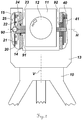
- Figure 1 shows an embodiment of the surveying device 1 according to the invention as a theodolite.
- the surveying device has a vertical axis V and a tilt axis H.
- the figure also shows the beam steering unit 11, the support 13 and the base 10 of the surveying device.
- the positioning device according to the invention is preferably in the support 13 provided, but can alternatively also be arranged in the beam steering unit 11.
- FIG. 2 shows the theodolite in a front view, with the relevant points of the bearing and the drive being cut out.
- the beam steering unit 11 contains a telescope 12 and a distance measuring device and is connected to the shaft 91 in a rotationally fixed manner.
- the shaft 91 has a conical bore for mounting by means of a ball 90.
- Another conical bore is incorporated in the cover 15 of the support 13 so that the shaft 91 is supported radially and axially in the support by clamping the ball 90 between the two conical bores.
- the pre-tensioning required for this is primarily achieved by the pre-tensioning magnets 22 in the example shown.
- the axial forces that arise during operation of the axial flux motor (20, 21, 23, 24) can also be actively used to influence the bearing forces or bearing preload.
- the bearing preload can be specifically weakened or increased.
- the circuit board 20 is fixedly connected to the cover 15 or alternatively to the support 13.
- Coils 21 are arranged in a ring on the circuit board 20, each of which is wired to the circuit board 20 via electrical conductors.
- the coils 21 are wound so that their winding axis is axially parallel to the tilting axis H.
- the prestressing magnets 22 still attract the rotor disk 23 even when the positioning device is out of operation.
- Rotor magnets 24 are arranged circumferentially on the outside of the rotor disk 23, which is connected non-rotatably to the shaft 91.
- These rotor magnets 24 can for example be standardized permanent magnets, but also custom-made products or a homogeneous remanent magnetic ring body, the was magnetized accordingly in sections.
- the magnets are also arranged in a ring so that they face the coils axially.
- the polarity of the rotor magnets 24 is alternately "north" and "south” along the circumference of the rotor disk.
- the control and evaluation unit which is responsible for activating the coils 21, can for example also be integrated in or on the circuit board 20 or be located at another point in the surveying device.
- the shaft 91 is slide-mounted in a conventional V-bearing 92, with a code disk 41 being arranged on the shaft 91 in this part of the support 13, which in combination with the transmitted light angle sensor 40 forms an angle measuring system.
- control units are, for example, regulation, control, evaluation units or other electronic components relating to the control.
- the rotor magnets 24 can be embodied by standard magnets, special magnets or by a one-piece remanent magnet which is magnetized in alternating sections around the circumference. In such a remanent magnet, which consists of a homogeneous material, the magnets are incorporated by polarization or polarization.
- the rotor and / or stator have an opening on the axis.
- the rotatable part of the positioning device is considered to be the rotor and the stationary part of the positioning device is considered to be the stator.
- the coils 21 can also be embodied by conductor tracks or electrical conductors embedded directly on the circuit board 20, directly on or in an electrically non-conductive carrier.
- the circuit board 20 accommodates further electronic components used for purposes other than the positioning device, in particular other conductor tracks.
- the flux deflecting element 25 is designed to be uniformly planar so that there are no cogging torques between the stator and rotor, in particular when the coils (21) are not traversed by electrical current.
- the rotor disk 23 is non-rotatably connected to a shaft 91 and the shaft 91 is non-rotatably connected to the beam steering unit 11 or the support 13.
- the bearing preload of the bearing of the shaft 91 can be specifically influenced.
- the rotor disk 23 is surrounded axially on both sides by a stationary unit each having coils arranged in a ring, the rotor magnets 24 being opposite the coils 21.
- the remaining movement of the beam steering component is used in order to be able to operate the positioning device as a generator or dynamo in a braking energy recovery mode. This is particularly advantageous for battery-operated surveying devices.
- the coils 21 are excited via the control means in such a way that the resulting and rotating electromagnetic fields exert extensive magnetic forces on the rotor disk 23 equipped with rotor magnets 24.
- the coils 21 are excited via the control means in such a way that the stationary electromagnetic fields that arise thereby exert circumferential magnetic forces blocking the rotation on the rotor disk 23 equipped with rotor magnets 24.
- the positioning device can also alternatively be arranged in the beam steering unit 11 by means of appropriate structural measures.
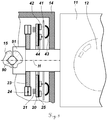
- FIG. 3 shows the enlarged detailed view of a further embodiment.
- the rotor disk 23 is non-rotatably connected to the shaft 91 and has rotor magnets 24 arranged in a circle around the circumference.
- the flow deflecting element 25 has signal transmitter 42 and signal encoder 44 which, in combination with reflectors 43 and code disk 41, form an angle measuring system.
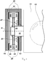
- Figure 4 shows a two-sided structure of the axial flux motor as a positioning unit in a surveying device.
- the two-sided construction enables a significantly higher torque to be achieved.
- the printed circuit boards 20 connected to the support 13 via a support structure 26 have flux deflection elements 25 on the outside and coils 21 on the inside, which are arranged in a ring around the tilting axis H. Between the rings of coils 21 is the rotor disk 23 with their also placed in a ring on the circumference rotor magnets 24.
- the rotor disk 23 is rigidly connected to the shaft 91 which carries the beam steering unit 11.
- a radial mounting of the shaft 91 in the support 13 can be done for example by roller bearings.
- the axial bearing can be done by the "magnetic bracing" of the rotor in the two-sided axial flux machine.
- An angle measuring system is implemented on the basis of code markings 27 applied to the rotor disk 23, which are continuously scanned by a reflection angle sensor 45 arranged on one of the circuit boards 25.
- Figures 5a to 5c show different variants of the rotor, namely the rotor disk 23 equipped with rotor magnets 24.
- Figure 5a shows a rotor disk 23 with standard magnets 24 arranged in a ring thereon with alternating polarity.
- Figure 5b shows custom-made magnets embedded in the rotor disk 23 and
- Figure 5c shows a one-piece remanent magnet made of homogeneous material, into which the magnetic polarity was incorporated in a previous manufacturing step.
- Figures 6a and 6b show variants of the coils 21 on the stator.
- Figure 6a shows coils 21 arranged in a ring on the circuit board 20, created by winding, for example, copper wires.
- the axis of the coil turns is parallel to the axis of rotation (tilt axis, standing axis) and perpendicular to the board 20.
- Figure 6b a circuit board 20 with integrated coils 21 is shown. These can, for example, be "printed on" or cast.
- Figure 7 shows a mounted axial flow machine for use in a measuring device according to the invention in two-sided construction and Figure 8 the associated exploded view.
- the printed circuit boards 20 and the flux deflection elements 25 are mounted in a support structure 26.
- the support structure 26 can alternatively also be realized as a one-piece component by the printed circuit board 20 and the flow deflecting element 25, in that different functional layers of metal, ceramic and / or plastic are connected to one another, in particular laminated. This multi-layer composite saves even more tree space.
- the circuit boards 20 carry the coils 21.
- the rotor disk 23 with its circumferentially arranged rotor magnets 24 is located between the coil rings and is freely movable there.
- the shaft to be positioned or the element to be driven is to be attached to the inner bore or to the flange of the rotor disk 23.
Landscapes
- Engineering & Computer Science (AREA)
- Physics & Mathematics (AREA)
- General Physics & Mathematics (AREA)
- Radar, Positioning & Navigation (AREA)
- Remote Sensing (AREA)
- Power Engineering (AREA)
- Electromagnetism (AREA)
- Computer Networks & Wireless Communication (AREA)
- Connection Of Motors, Electrical Generators, Mechanical Devices, And The Like (AREA)
- Reciprocating, Oscillating Or Vibrating Motors (AREA)
- Brushless Motors (AREA)
Description
- Die vorliegende Erfindung betrifft die Oberbegriffe der unabhängigen Ansprüche. Damit befasst sich die Erfindung allgemein mit Vermessungsgeräten ausgebildet als Totalstation, Tracker oder Theodolit.
- In vielen Vermessungsgeräten ist die Modifizierung von gerichteter optischer Messstrahlung, z.B. durch Ausrichtung von den Strahlgang integrierenden Komponenten oder eine Fokussierung auf ein Ziel, erforderlich. Dabei muss diese Modifizierung präzise und bei dynamischen Anwendungen auch hinreichend schnell erfolgen, so dass beispielsweise grosse zu bewegende Massen nachteilig sind. Zudem erfordert die Feldtauglichkeit des Messgerätes grundsätzlich Robustheit des Antriebs sowie einen geringen Energiebedarf.
- Ein industrielles oder geodätisches Vermessungsgerät weist in der Regel eine Stehachse und eine Kippachse auf, welche gelagert sind und angetrieben werden. Beispiele für solche Messgeräte sind Totalstationen, Theodoliten oder Tachymeter, welche - auch zusammen mit integrierten automatischen Zielerfassungs- und Zielverfolgungs-Einrichtungen - für vielfältige Vermessungsaufgaben zum Einsatz kommen, wobei sowohl eine Datengewinnung als auch eine reine Überprüfung, wie z.B. in der Bauwerksüberwachung, in Frage kommen. Andere Messgeräte sind beispielsweise Systeme wie Lasertracker, Laserscanner oder Profiler, die im abtastenden Verfahren Topographien von Oberflächen als dreidimensionale Punktwolken aufnehmen. In bisherigen Lösungen kommen für diese Zwecke häufig Servomotoren zum Einsatz, die den Antrieb der Komponenten darstellen. Servomotoren mit einem nachgelagerten Getriebe sind komplex, teuer, wartungsintensiv und verschleissanfällig. Kombinationen von Elektromotoren und Getrieben sind zudem nicht in der Lage hohe Achsgeschwindigkeiten, wie sie zum Scannen benötigt werden, mit genauer und langsamer Feinanzielung bzw. einer Positionierung zu verbinden, da in der Regel der nutzbare Drehzahlbereich der Motoren oder Getriebe hierfür nicht gross genug ist.
- Für minimale Verstellwege können hingegen alternative Antriebselemente, wie z.B. elektrostatische Kämme, verwendet werden. Aus der
US 7,999,921 , derEP1619468 und der -
EP 1 314 960 sind z.B. geodätische Messgeräte bekannt, in denen Piezoelemente zur Bewegung einer Strahlungsquelle im Gehäuse des Messgeräts verwendet werden. Allerdings ist der verfügbare Bewegungsspielraum durch die Deformation des Piezoelementes beschränkt. Insbesondere eine fortlaufende und unbeschränkte Bewegung als Endlostrieb, wie sie z.B. für eine Rotation benötigt wird, ist durch einen Piezo-Aktuator bzw. ein Piezostellelement oder elektrostatische Vorrichtungen nicht realisierbar. Piezoantriebe basieren auf dem Prinzip des Reibschlusses und sind daher verschleissbehaftet. Stellenweise können auch Prinzip bedingt Geräusche entstehen. Piezoantriebe sind überdies hinaus für hohe Drehzahlen ungeeignet. Für das Scannen von Objekten ist es oft vorteilhaft, wenn der Messstrahl oszillierend bewegt wird. Diese Anwendung ist wegen des Verschleisses nicht dauerhaft möglich. -
US 2009/067461 A1 zeigt einen Laserrotator, der, insbesondere zur Eliminierung von Lagerspiel, mit einem Leiterplattenstator und einem mit Magneten bestückten Rotor ausgestattet ist, wobei das Pentaprisma des Rotators mit dem Rotor verbunden ist. -
DE 20 2007 017 856 U1 zeigt einen Servomotor, dessen Schaltungsträger Teil des Stators ist und wobei auch eine mit Dauermagneten eines Rotors zusammenwirkende Motorspulen auf dem Schaltungsträger vorgesehen sind. -
EP 0 624 945 A1 zeigt einen Motor mit einem dauermagnetischen Rotor und einem elektromagnetischen Stator, wobei der Stator ebenfalls durch auf einer Trägerplatte angebrachte Wicklungen realisiert ist. - Bürstenlose Gleichstrommotoren sind generell im Stand der Technik bekannt, dies etwa aus Wikipedia.
- Asynchronantriebe sind zwar bei kontinuierlichen, fortwährenden, gleichförmigen Bewegungen gern genutzte Lösungen, können aber für Positionieraufgaben in Vermessungsinstrumenten nicht verwendet werden, da die statische Regelung von Asynchronmotoren nahezu unmöglich ist.
- Synchronmotoren wären in radialer Bauform für Vermessungsgeräte geeignet, sind jedoch bauformbedingt mit Rastmomenten behaftet. Ein in einem Laserscanner verbauter bürstenloser Synchronmotor ist in der
US 2009/0052288 A1 gezeigt. Bei unbestromter Wicklung richten sich die Magnete des Rotors also gegenüber dem Statorblech aus, wodurch sich die Achse von der Sollposition wegbewegt. Eine permanente Regelung bzw. Bestromung ist notwendig, um solche Antriebe auf Position zu halten. Für Vermessungsgeräte wie Totalstationen ist eine präzise langsame Bewegung notwendig, um das Teleskop auf ein Ziel ausrichten zu können. Diese gleichmässige Bewegung ist durch das Rastmoment nur schwer erreichbar. Oft ist es erwünscht einen möglichst grossen freien Innendurchmesser des Rotors zu haben, um den Raum für die Durchführung von optischen Strahlen und/oder Kabeln zu nutzen. Funktionsbedingt steigt jedoch bei diesem Motortyp dann aber auch der Aussendurchmesser sehr stark an, wodurch der Motor völlig überdimensioniert sein kann. Zudem generieren Synchronmotoren in radialer Bauform toleranzbedingt eine radiale, statische Kraft, die bei Präzisionsgleitlagern unzulässig ist. - Aufgabe der Erfindung ist die Bereitstellung eines verbesserten Vermessungsgerätes mit Positioniereinrichtung, die die oben beschriebenen Nachteile vermeidet.
- Diese Aufgabe wird durch die Verwirklichung der kennzeichnenden Merkmale der unabhängigen Ansprüche gelöst. Merkmale, die die Erfindung in alternativer oder vorteilhafter Weise weiterbilden, sind den abhängigen Patentansprüchen zu entnehmen.
- Die Erfindung beruht darauf, das Vermessungsgerät so auszubilden, dass eine Verwendung eines Axialflussmotors als Positioniereinrichtung möglich ist und dabei auf zusätzliche Kraftübertragungselemente, wie Kupplungen oder Getriebe, verzichtet werden kann. Mittels einer Steuer- und Auswerteeinheit ist der Axialflussmotor so ansteuerbar, dass die Vortriebskräfte des Axialflussmotors frei konfigurierbar sind. Im Speziellen können hierfür bekannte Ansteuertechnologien wie Spannungs-, Frequenz- und/oder Phasendifferenzkontrolle angewendet werden.
- Der erfindungsgemässe Einsatz von Axialflussmotoren als Positioniereinrichtung erlaubt die Verwendung als skalierbares Achs-Positioniersystem für die Bewegung und Positionierung der Strahllenkeinheit des Messgerätes. Es kann bei jeweiliger Verbauung der Positioniereinrichtung eine Bewegung um die Kippachse und um die Stehachse des Messgerätes bewirkt werden, um einen zur Messung verwendeten Strahlgang, z.B. durch eine Ausrichtung bzw. Änderung der Ausrichtung, zu modifizieren.
- Ein Axialflussmotor besteht aus einem Rotor und einem Stator, die magnetisch miteinander in Wechselwirkung treten. Der Rotor weist mehrere umfänglich an einer Rotorscheibe fixierte Permanentmagnete und der Stator mehrere, den Permanentmagneten axial gegenüberliegende Spulen auf. Diese Korrelation (Rotor:Permanentmagnete, Stator:Spulen) ist nicht zwingend erforderlich, jedoch technisch geeigneter als eine entsprechend umgekehrte Korrelation. Die Spulen müssen nämlich mit der Steuer- und Auswerteeinheit verkabelt werden, durch welche sie elektrisch so angeregt werden, dass mit den daraus resultierenden elektro-magnetischen Feldern der Spulen die Permanentmagnete zum Rotieren gebracht werden. Axialflussantriebe der beschriebenen Art lassen sich mit vergleichsweise wenigen Komponenten realisieren und mit weitgehend automatisierten Fertigungstechnologien kostengünstig herstellen. Insbesondere das Ein- bzw. Aufgiessen der Spulen in bzw. auf die Platine zu spiralförmigen Leiterbahnen ist ein rationelles Herstellungsverfahren, das einen sehr flachen Aufbau ermöglicht. Dies impliziert ebenfalls das Einlassen eines diskreten Leiters in die Leiterplatte sowie ein Aufdrucken im Multilayerverfahren.
- Da die Kraftübertragung berührungsfrei und stattfindet, ist die Positioniereinrichtung sehr reibungs- und geräuscharm. Dadurch verfügt die Positioniereinrichtung über eine sehr hohe Dynamik und auch die Fähigkeit, kleine wie hohe Drehzahlen zu erreichen. Die Spulen sind bevorzugt ohne prägnante Eisenkerne ausgeführt, weshalb an keiner Position ein Rastmoment herrscht. Vielmehr sind die Spulen zur Effektivitätssteigerung mit einer gleichmässigen Flussumlenkung hinterlegt, die also keine Rastpositionen zulässt.
- Bei Bremsvorgängen, wie sie im oszillierenden Betrieb des Vermessungsgerätes üblicherweise vorkommen, kann der Antrieb gar als Generator wirken und Energie zurückgewinnen, was insbesondere bei Batteriebetrieb die Mobilität des Vermessungsgerätes steigert.
- Trotz dem, dass die Kraftübertragung berührungslos, weil elektro-magnetisch, erfolgt, lässt sich mit der erfindungsgemässen Positioniereinrichtung eine Rutschkupplung realisieren, die man sonst nur von an einander abreibenden Komponenten kennt. Dazu wird bei entsprechender Ansteuerung der Spulen ein Widerstandsmoment erzeugt, wobei eine Verdrehung von Stator und Rotor aber zugelassen wird. Dadurch erhält man eine haptische Rückmeldung bzw. ein Force Feedback bei der händischen Verdrehung der Strahllenkeinheit. Auch kann die Steuer- und Auswerteeinheit die Spulen in einem Regelkreis so regeln, dass ein für die händische Bedienung übliches Drehmoment oder eine typische Verdrehung an der Achse erkannt und dann entweder gesperrt, unterstützt oder erschwert wird. Ein Kriterium für das, ggf. kraftmässig beeinflusste, Zulassen einer Verdrehung wäre die Erkennung der Überschreitung eines Schwellenmomentes.
- Das oben beschriebene haptische Verhalten der Positioniereinrichtung kann auch über eine manipulative Veränderung der Lagervorspannung (Be-/Entlastung des Lagers) mittels der beim Betrieb des Axialflussmotors entstehenden und beeinflussbaren magnetischen Axialkraft erzielt werden.
- Besitzt die Positioniereinrichtung einen zweiseitigen Aufbau, so kann die axiale Kraft, die prinzipbedingt durch den laufenden Antrieb entsteht, betragsmässig eingestellt werden. So kann gezielt z.B. ein axialkraftfreies Verhalten eingestellt werden, aber auch eine definiert verbleibende Axialkraft, um z.B. ein Lager vorzuspannen.
- Die erfindungsgemässe Positioniereinrichtung lässt sich für das Vermessungsgerät weiters derart auslegen, dass bei gross gewähltem Innendurchmesser der Aussendurchmesser immer noch relativ klein bleibt. Dieser Vorteil kann dahin gehend ausgeschöpft werden, dass im Inneren der Positioniereinrichtung ein grösserer Hohlraum zur Nutzung anderer Komponenten berücksichtigt werden kann, ohne dass nach aussen hin das Gehäuse überdimensioniert werden müsste. Auch ist ein entscheidender Vorteil der Erfindung, dass die Positioniereinrichtung bezüglich ihres Ausmasses relativ flexibel, insbesondere sehr schmal dimensioniert werden kann.
- Gemäss einer weiteren Ausführungsform ist der Axialflussmotor kombinierbar mit einem Kugelpunktlager. Diese Kombination erweist sich als besonders vorteilhaft, da die quasi als Nebeneffekt auftretende axiale Magnetkraft des Axialflussmotors der Vorspannung eines solchen Kugelpunktlagers zumindest teilweise zuträglich ist. Ein Kugelpunktlager zeichnet sich hierbei dadurch aus, dass mittels einer Kugel ein Rotor relativ zu einem Stator gelagert ist, wobei die drei beteiligten Komponenten zentriert und stabil aneinander ausgerichtet bleiben, indem Rotor und Stator einen speziell geformten, zentrierenden Sitz für die Kugel aufweisen. Dieser Sitz ist eine Kavität, die die Kugel selbstzentrierend und stabil einfasst. Die Kavität kann beispielsweise torisch, kegelförmig, konisch, sphärisch oder asphärisch sein. Die Kugel ist dabei nur soweit in der jeweiligen Kavität versenkt bzw. ragt noch soweit aus der jeweiligen Kavität heraus, dass der Rotor an der Kugel und die Kugel am Stator abgleiten, ohne dass sich Rotor und Stator berühren.
- Auch lässt sich ein erfindungsgemässes Vermessungsgerät so gestalten, dass die Positioniereinrichtung für weitere ihrer Achsen verwendet werden kann.
- Die erfindungsgemässe Vorrichtung wird nachfolgend anhand von in den Zeichnungen schematisch dargestellten konkreten Ausführungsbeispielen rein beispielhaft näher beschrieben, wobei auch auf weitere Vorteile der Erfindung eingegangen wird. Im Einzelnen zeigen
- Fig.1:
- ein erfindungsgemässes Vermessungsgerät;
- Fig.2:
- ein erfindungsgemässes Vermessungsgerät mit der Lagerung und der Positioniereinrichtung im Ausschnitt;
- Fig.3:
- ausschnittweise die Lagerung und Positioniereinrichtung eines ersten Ausführungsbeispiels eines erfindungsgemässen Vermessungsgerätes;
- Fig.4:
- ausschnittweise die Lagerung und Positioniereinrichtung eines zweiten Ausführungsbeispiels eines erfindungsgemässen Vermessungsgerätes;
- Fig.5a,b,c:
- mit Magneten bestückte Rotoren;
- Fig.6a,b:
- mit Spulen bestückte Platinen;
- Fig.7:
- den Zusammenbau einer erfindungsgemässen Positioniereinheit in der seitlichen Schnittdarstellung;
- Fig.8:
- eine erfindungsgemässe Positioniereinheit in der Explosionsansicht.
-
Figur 1 zeigt ein Ausführungsbeispiel des erfindungsgemässen Vermessungsgerätes 1 als Theodoliten. Das Vermessungsgerät weist eine Stehachse V und eine Kippachse H auf. Weiters zeigt die Figur die Strahllenkeinheit 11, die Stütze 13 sowie die Basis 10 des Vermessungsgerätes. Die erfindungsgemässe Positioniereinrichtung ist bevorzugt in der Stütze 13 vorgesehen, kann aber alternativ auch in der Strahllenkeinheit 11 angeordnet sein. -
Figur 2 zeigt den Theodoliten in der Vorderansicht, wobei die relevanten Stellen der Lagerung und des Antriebs ausgeschnitten sind. Die Strahllenkeinheit 11 beinhaltet ein Teleskop 12 und eine Entfernungsmesseinrichtung und ist verdrehfest mit der Welle 91 verbunden. Die Welle 91 weist zur Lagerung mittels einer Kugel 90 eine Kegelbohrung auf. Eine weitere Kegelbohrung ist im Deckel 15 der Stütze 13 eingearbeitet, sodass die Welle 91 durch ein Einklemmen der Kugel 90 zwischen den beiden Kegelbohrungen radial und axial in der Stütze gelagert ist. Die dazu benötigte Vorspannung wird im gezeigten Beispiel primär durch die Vorspannmagnete 22 erzielt. Die Axialkräfte, die beim Betrieb des Axialflussmotors (20,21,23,24) entstehen, können zusätzlich auch aktiv zur Beeinflussung der Lagerkräfte bzw. Lagervorspannung benützt werden. So kann beispielsweise die Lagervorspannung also gezielt abgeschwächt oder verstärkt werden. Die Leiterplatte 20 ist mit dem Deckel 15 oder alternativ mit der Stütze 13 fix verbunden. Kranzförmig auf der Leiterplatte 20 sind Spulen 21 angeordnet, die jeweils über elektrische Leiter mit der Leiterplatte 20 verkabelt sind. Die Spulen 21 sind so gewickelt, dass ihre Windungsachse achsparallel zur Kippachse H liegt. Die Vorspannmagnete 22 ziehen die Rotorscheibe 23 auch dann noch an, wenn die Positioniereinrichtung ausser Betrieb ist. Auf der drehfest mit der Welle 91 verbundenen Rotorscheibe 23 sind aussen umfänglich Rotormagnete 24 angeordnet. Diese Rotormagnete 24 können zum Beispiel standardisierte Permanentmagnete sein, aber auch Sonderanfertigungen oder ein homogener remanentmagnetischer Ringkörper, der entsprechend abschnittsweise magnetisiert wurde. Die Magnete sind ebenfalls kranzförmig angeordnet, sodass sie den Spulen axial gegenüberstehen. Die Polung der Rotormagnete 24 ist entlang des Rotorscheibenumfangs abwechselnd "Nord" und "Süd". Die Steuer- und Auswerteeinheit, welche für die Ansteuerung der Spulen 21 zuständig ist, kann z.B. auch in bzw. auf der Leiterplatte 20 integriert sein oder sich an einer anderen Stelle im Vermessungsgerät befinden. - Auf der anderen Seite ist die Welle 91 in einem konventionellem V-Lager 92 gleitgelagert, wobei in diesem Teil der Stütze 13 eine Codescheibe 41 auf der Welle 91 angeordnet ist, die in Kombination mit dem Durchlichtwinkelsensor 40 ein Winkelmesssystem bildet.
- Das Vermessungsgerät 1 hat also wenigstens eine optoelektronische Entfernungsmesseinrichtung mit einem Messstrahlgang, eine Basis 10 zur Platzierung des Vermessungsgerätes 1, eine auf der Basis 10 um eine Stehachse V drehbar gelagerte Stütze 13 zur azimuthalen Ausrichtung des optischen Strahlgangs, eine in der Stütze 13 um eine Kippachse H drehbar gelagerte Strahllenkeinheit 11 zur elevativen Ausrichtung des Messstrahlgangs, ein Winkelmesssystem zur Messung der Achsstellungen und einer ansteuerbaren, die Strahllenkeinheit 11 bzw. die Stütze 13 antreibende Positioniereinrichtung, wobei die Positioniereinrichtung mehrere ringförmig um die Kippachse H und/oder Stehachse V und ortsfest angeordnete Spulen 21 mit zur Kippachse H bzw. Stehachse V achsparallelen Windungsachsen aufweist und die Spulen 21 durch Ansteuermittel so ansteuerbar sind, dass sie mit mehreren, auf einer Rotorscheibe 23 umfänglich in abwechselnder Polung benachbarten und axial gegenüber den Spulen 21 angeordneten Rotormagneten 24 in Wechselwirkung treten, um folgende Funktionen zu gewährleisten:
- Ausüben eines Drehmomentes auf die Strahllenkeinheit 11 bzw. die Stütze 13,
- Ermöglichung der freien händischen Beweglichkeit der Strahllenkeinheit 11 bzw. der Stütze 13 und
- Sperren der Beweglichkeit der Strahllenkeinheit 11 bzw. der Stütze 13.
- Hierbei bedeutet eine freie händische Beweglichkeit, dass die Beweglichkeit zumindest derart entsperrt ist, dass ein Benutzer mit normaler Muskelkraft eine übliche Verdrehung der Komponente herbeiführen kann. Als Ansteuermittel sind beispielsweise Regelungs-, Steuer-, Auswerteeinheiten oder weitere, die Ansteuerung betreffende elektronische Bauteile zu verstehen.
- Die Rotormagnete 24 können durch Standardmagnete, Spezialmagnete oder durch einen einteiligen Remanentmagneten verkörpert werden, der umfänglich abschnittsweise alternierend magnetisiert ist. In einem solchen Remanentmagneten, der aus homogenem Material besteht, sind die Magnete durch Polarisierung bzw. Polung eingearbeitet.
- Die Spulen 21 sind auf einer Seite der Leiterplatte 20 angeordnet, insbesondere wobei ein Flussumlenkelement 25 auf der anderen Seite der Leiterplatte 20 angeordnet, insbesondere auflaminiert ist, oder ein Flussumlenkelement 25 und die Leiterplatte 20 Bestandteile einer Verbundplatte sind, wobei die Verbundplatte in einer Kombinierung der Materialien
- Metall und
- Keramik und/oder
- Kunststoff
- Rotor und/oder Stator verfügen über eine achszentrale Öffnung. Als Rotor gilt der drehbare Teil der Positioniereinrichtung und als Stator gilt der ortsfeste Teil der Positioniereinrichtung.
- Die Spulen 21 können anstelle von Kupferspulen auch durch auf der Leiterplatte 20 direkt eingebettete Leiterbahnen oder elektrische Leiter direkt auf oder in einem elektrisch nicht leitenden Träger verkörpert werden. Die Leiterplatte 20 nimmt weitere, für von der Positioniereinrichtung verschiedene Zwecke verwendete, elektronische Komponenten, insbesondere andere Leiterbahnen auf.
- Das Flussumlenkelement 25 ist gleichmässig planar ausgebildet, so dass zwischen Stator und Rotor keine Rastmomente herrschen, insbesondere wenn die Spulen (21) nicht von elektrischem Strom durchflossen werden.
- Die Rotorscheibe 23 drehfest mit einer Welle 91 und die Welle 91 drehfest mit der Strahllenkeinheit 11 bzw. der Stütze 13 verbunden sind.
- Mit einer durch gezielte Ansteuerung der Spulen 21 erreichbaren Axialkraft ist die Lagervorspannung der Lagerung der Welle 91 spezifisch beeinflussbar.
- Die Rotorscheibe 23 ist axial beidseitig von je einer ortsfesten und ringförmig angeordnete Spulen aufweisenden Einheit umgeben, wobei die Rotormagnete 24 den Spulen 21 gegenüberstehen.
- Bei einem Abbremsen der Positioniereinrichtung kann eine Energierückgewinnung stattfindet. Dabei wird die restliche Bewegung der Strahllenkkomponente ausgenutzt, um damit in einem Bremsenergierückgewinnungsmodus die Positioniereinrichtung als Generator bzw. Dynamo betreiben zu können. Dies ist insbesondere für akkubetriebene Vermessungsgeräte von Vorteil.
- Zum Ausüben eines Drehmomentes auf die Strahllenkeinheit 11 werden die Spulen 21 über die Ansteuermittel derart angeregt, dass die dabei entstehenden und rotierenden elektro-magnetischen Felder auf die mit Rotormagneten 24 bestückte Rotorscheibe 23 umfängliche Magnetkräfte ausüben.
- Zur Ermöglichung der freien händischen Beweglichkeit der Strahllenkeinheit 11 bzw. der Stütze 13 werden die Spulen 21 in einen unangeregten Zustand versetzt, sodass
- die Wechselwirkung zwischen den Rotormagneten 24 und den Spulen 21 aufgehoben wird und somit die Beweglichkeit der Rotorscheibe 23 gegenüber dem Stator frei von Magnetkräften ist oder
- die Spulen 21 derart geregelt angeregt werden, dass bei erkanntem händisch auf die Strahllenkeinheit 11 bzw. auf die Stütze 13 ausgeübtem Drehmoment, insbesondere bei Überschreiten eines Schwellmomentes, eine Verdrehung der Strahllenkeinheit 11 bzw. der Stütze im Sinne einer Rutschkupplung zugelassen wird, wobei anhand der Ansteuerung der Spulen 21 eine gezielte haptische Kraftrückkopplung im Sinne eines Force Feedbacks der Verdrehung entgegen richtbar ist.
- Zur Einschränkung der Beweglichkeit der Strahllenkeinheit 11 bzw. der Stütze 13 die Spulen 21 über die Ansteuermittel derart angeregt werden, dass die dabei entstehenden und ortsfesten elektro-magnetischen Felder auf die mit Rotormagneten 24 bestückte Rotorscheibe 23 umfängliche, die Rotation sperrende Magnetkräfte ausüben.
- Durch entsprechende konstruktive Massnahmen kann die Positioniereinrichtung auch alternativ in der Strahllenkeinheit 11 angeordnet sein.
-
Figur 3 zeigt die vergrösserte Detailansicht eines weiteren Ausführungsbeispiels. Die Rotorscheibe 23 ist drehfest mit der Welle 91 verbunden und weist umfänglich kreisförmig angeordnete Rotormagnete 24 auf. Gegenüberliegend befindet sich eine in der Stütze 13 ortsfest fixierte Leiterplatte 20 mit dem Flussumlenkelement 25 auf der Rückseite. Das Flussumlenkelement 25 Signalsender 42 und Signalencoder 44 auf, die in Kombination mit den Reflektoren 43 und der Codescheibe 41 ein Winkelmesssystem bilden. -
Figur 4 zeigt einen zweiseitigen Aufbau des Axialflussmotors als Positioniereinheit in einem Vermessungsgerät. Durch den zweiseitigen Aufbau lässt sich ein deutlich höheres Drehmoment erzielen. Die mit der Stütze 13 über eine Tragstruktur 26 verbundenen Leiterplatten 20 weisen nach aussen hin Flussumlenkelemente 25 und innen Spulen 21 auf, die ringförmig um die Kippachse H angeordnet sind. Zwischen den Ringen aus Spulen 21 ist die Rotorscheibe 23 mit ihren ebenfalls ringförmig am Umfang angeordneten Rotormagneten 24 platziert. Die Rotorscheibe 23 ist starr mit der Welle 91 verbunden, die die Strahllenkeinheit 11 trägt. Eine radiale Lagerung der Welle 91 in der Stütze 13 kann beispielsweise durch Wälzlager erfolgen. Die axiale Lagerung kann durch das "magnetische Verspannen" des Rotors in der zweiseitigen Axialflussmaschine erfolgen. Ein Winkelmesssystem ist anhand auf die Rotorscheibe 23 aufgebrachter Codemarkierungen 27 realisiert, die von einem auf einer der Leiterplatten 25 angeordneten Reflektionswinkelsensor 45 kontinuierlich abgescannt wird. -
Figur 5a bis 5c zeigen verschiedene Varianten des Rotors, namentlich der mit Rotormagneten 24 ausgestatteten Rotorscheibe 23.Figur 5a zeigt eine Rotorscheibe 23 mit ringförmig darauf angeordneten Standardmagneten 24 mit abwechselnder Polung.Figur 5b zeigt in die Rotorscheibe 23 eingelassene spezialangefertigte Magneten undFigur 5c zeigt einen aus homogenem Material bestehenden, einstückigen Remanentmagneten, dem in einem vorangehenden Fertigungsschritt die magnetische Polung eingearbeitet wurde. -
Figur 6a und 6b zeigen Varianten der Spulen 21 am Stator.Figur 6a zeigt ringförmig auf der Leiterplatte 20 angeordnete Spulen 21, erstellt durch die Wicklung von z.B. Kupferdrähten. Die Achse der Spulenwindungen ist parallel zur Rotationsachse (Kippachse, Stehachse) und senkrecht zur Platine 20. InFigur 6b ist eine Leiterplatte 20 mit integrierten Spulen 21 gezeigt. Diese können beispielsweise "aufgeprintet" oder eingegossen sein. -
Figur 7 zeigt eine montierte Axialflussmaschine zur Verwendung in einem erfindungsgemässen Messgerät im zweiseitigen Aufbau undFigur 8 die dazugehörige Explosionszeichnung. In einer Tragstruktur 26 werden die Leiterplatten 20 und die Flussumlenkelemente 25 (auch Kurzschlussbleche genannt) montiert. Die Tragstruktur 26 kann alternativ auch durch die Leiterplatte 20 und das Flussumlenkelement 25 als einteiliges Bauteil verwirklicht werden, indem entsprechend unterschiedliche funktionelle Lagen aus Metall, Keramik und/oder Kunststoff miteinander im Verbund stehen, insbesondere laminiert sind. Dieser mehrschichtige Verbund spart nochmals an Baumraum. - Die Leiterplatten 20 tragen die Spulen 21. Die Rotorscheibe 23 mit ihren umfänglich angeordneten Rotormagneten 24 befindet sich zwischen den Spulen-Kränzen und ist dort frei beweglich. An der Innenbohrung oder am Flansch der Rotorscheibe 23 ist die zu positionierende Welle bzw. das anzutreibende Element zu befestigen.
- Es versteht sich, dass die vorangehend gezeigten und erklärten Figuren nur mögliche Ausführungsbeispiele schematisch darstellen. Insbesondere wird darauf hingewiesen, dass die explizit dargestellten und erklärten Beispiele ausnahmslos sowohl separat voneinander als auch in jeglicher Kombination miteinander einsetzbar sind.
Claims (13)
- Vermessungsgerät (1) ausgebildet als Totalstation, Tracker oder Theodolit, mit wenigstens• einer opto-elektronischen Entfernungsmesseinrichtung mit einem Messstrahlgang,• einer Basis (10) zur Platzierung des Vermessungsgerätes (1),• einer auf der Basis (10) um eine Stehachse (V) drehbar gelagerten Stütze (13) zur azimuthalen Ausrichtung des optischen Strahlgangs,• einer in der Stütze (13) um eine Kippachse (H) drehbar gelagerten Strahllenkeinheit (11) zur elevativen Ausrichtung des Messstrahlgangs,• einem Winkelmesssystem zur Messung der Achsstellungen• einer ansteuerbaren, die Strahllenkeinheit (11) bzw. die Stütze (13) antreibenden Positioniereinrichtung und• Ansteuermitteln,dadurch gekennzeichnet, dass
die Positioniereinrichtung mehrere ringförmig um die Kippachse (H) und/oder Stehachse (V) und ortsfest angeordnete Spulen (21) mit zur Kippachse (H) bzw. Stehachse (V) achsparallelen Windungsachsen aufweist und die Spulen (21) durch die Ansteuermittel so angesteuert werden, dass sie mit mehreren, auf einer Rotorscheibe (23) umfänglich in abwechselnder Polung benachbarten und axial gegenüber den Spulen (21) angeordneten Rotormagneten (24) in Wechselwirkung treten, um die folgenden Funktionen zu gewährleisten:• Ausüben eines Drehmomentes auf die Strahllenkeinheit (11) bzw. die Stütze (13),• Ermöglichung der freien händischen Beweglichkeit der Strahllenkeinheit (11) bzw. der Stütze (13) und• Sperren der Beweglichkeit der Strahllenkeinheit (11) bzw. der Stütze (13),wobei die Spulen (21) auf der einen Seite einer Leiterplatte (20) angeordnet sind und ein Flussumlenkelement (25) auf der anderen Seite der Leiterplatte (20) angeordnet ist, und dabei das Flussumlenkelement (25) gleichmässig planar ausgebildet ist, so dass zwischen Stator und Rotor keine Rastmomente herrschen, insbesondere wenn die Spulen (21) nicht von elektrischem Strom durchflossen werden. - Vermessungsgerät (1) nach Anspruch 1,
dadurch gekennzeichnet, dass
die Rotormagnete (24) durch einen einteiligen Remanentmagneten verkörpert werden, der umfänglich abschnittsweise alternierend magnetisiert ist. - Vermessungsgerät (1) nach einem der vorherigen Ansprüche,
dadurch gekennzeichnet, dass
das Flussumlenkelement (25) auf der Leiterplatte (20) auflaminiert ist. - Vermessungsgerät (1) nach einem der vorherigen Ansprüche,
dadurch gekennzeichnet, dass
Rotor und/oder Stator über eine achszentrale Öffnung verfügen. - Vermessungsgerät (1) nach einem der vorherigen Ansprüche,
dadurch gekennzeichnet, dass
die Spulen (21) durch auf der Leiterplatte (20) eingebettete Leiterbahnen oder elektrische Leiter auf der Leiterplatte (20) verkörpert werden. - Vermessungsgerät (1) nach einem der vorherigen Ansprüche,
dadurch gekennzeichnet, dass
die Rotorscheibe (23) drehfest mit einer Welle (91) und die Welle (91) drehfest mit der Strahllenkeinheit (11) bzw. der Stütze (13) verbunden sind. - Vermessungsgerät (1) nach Anspruch 6,
dadurch gekennzeichnet, dass
mit einer durch gezielte Ansteuerung der Spulen (21) erreichbaren Axialkraft die Lagervorspannung der Lagerung der Welle (91) spezifisch beeinflussbar ist. - Vermessungsgerät (1) nach einem der vorherigen Ansprüche,
dadurch gekennzeichnet, dass
die Rotorscheibe (23) axial beidseitig von je einer ortsfesten und ringförmig angeordnete Spulen aufweisenden Einheit umgeben ist, insbesondere wobei eine dieser Einheiten die Leiterplatte (20) ist und wobei die Rotormagnete (24) den Spulen (21) gegenüberstehen. - Vermessungsgerät (1) nach einem der vorherigen Ansprüche,
gekennzeichnet durch
einen Betriebsmodus der Positioniereinrichtung zur Energierückgewinnung bei einem Abbremsen des Rotors. - Vermessungsgerät (1) nach einem der vorherigen Ansprüche,
dadurch gekennzeichnet, dass
zum Ausüben eines Drehmomentes auf die Welle (91) die Spulen (21) über die Ansteuermittel derart angeregt werden, dass die dabei entstehenden und rotierenden elektro-magnetischen Felder auf die mit Rotormagneten (24) bestückte Rotorscheibe (23) umfängliche Magnetkräfte ausüben. - Vermessungsgerät (1) nach einem der vorherigen Ansprüche,
dadurch gekennzeichnet, dass
zur Ermöglichung der freien händischen Beweglichkeit der Strahllenkeinheit (11) bzw. der Stütze (13)• die Spulen (21) in einen unangeregten Zustand versetzt werden, sodass die Wechselwirkung zwischen den Rotormagneten (24) und den Spulen (21) aufgehoben wird und somit die Beweglichkeit der Rotorscheibe (23) gegenüber dem Stator frei von Magnetkräften ist oder• die Spulen (21) derart geregelt angeregt werden, dass bei erkanntem händisch auf die Strahllenkeinheit (11) bzw. auf die Stütze (13) ausgeübtem Drehmoment,. insbesondere bei Überschreiten eines Schwellmomentes, eine Verdrehung der Strahllenkeinheit (11) bzw. der Stütze (13) im Sinne einer Rutschkupplung zugelassen wird, insbesondere wobei anhand der Ansteuerung der Spulen (21) eine gezielte haptische Kraftrückkopplung im Sinne eines Force Feedbacks der Verdrehung entgegen richtbar ist. - Vermessungsgerät (1) nach einem der vorherigen Ansprüche,
dadurch gekennzeichnet, dass
zur Einschränkung der Beweglichkeit der Strahllenkeinheit (11) bzw. der Stütze (13) die Spulen (21) über die Ansteuermittel derart angeregt werden, dass die dabei entstehenden und ortsfesten elektro-magnetischen Felder auf die mit Rotormagneten (24) bestückte Rotorscheibe (23) umfängliche, die Rotation sperrende Magnetkräfte ausüben. - Vermessungsgerät (1) nach einem der vorherigen Ansprüche,
dadurch gekennzeichnet, dass
die Positioniereinrichtung in der Strahllenkeinheit (11), in der Stütze (13) oder in der Basis (10) angeordnet ist. •
Priority Applications (3)
| Application Number | Priority Date | Filing Date | Title |
|---|---|---|---|
| EP14198460.9A EP3035076B1 (de) | 2014-12-17 | 2014-12-17 | Vermessungsgerät mit Positioniereinrichtung |
| CN201510876208.4A CN105716647B (zh) | 2014-12-17 | 2015-12-03 | 测量设备以及轴流式电机作为测量设备的定位装置的用途 |
| US14/963,011 US10260873B2 (en) | 2014-12-17 | 2015-12-08 | Surveying apparatus with positioning device |
Applications Claiming Priority (1)
| Application Number | Priority Date | Filing Date | Title |
|---|---|---|---|
| EP14198460.9A EP3035076B1 (de) | 2014-12-17 | 2014-12-17 | Vermessungsgerät mit Positioniereinrichtung |
Publications (2)
| Publication Number | Publication Date |
|---|---|
| EP3035076A1 EP3035076A1 (de) | 2016-06-22 |
| EP3035076B1 true EP3035076B1 (de) | 2020-08-19 |
Family
ID=52231859
Family Applications (1)
| Application Number | Title | Priority Date | Filing Date |
|---|---|---|---|
| EP14198460.9A Active EP3035076B1 (de) | 2014-12-17 | 2014-12-17 | Vermessungsgerät mit Positioniereinrichtung |
Country Status (3)
| Country | Link |
|---|---|
| US (1) | US10260873B2 (de) |
| EP (1) | EP3035076B1 (de) |
| CN (1) | CN105716647B (de) |
Cited By (1)
| Publication number | Priority date | Publication date | Assignee | Title |
|---|---|---|---|---|
| US20240027882A1 (en) * | 2022-07-20 | 2024-01-25 | Nodal Film Systems Llc | Camera Head with Integrated PCB Stator Motors |
Families Citing this family (10)
| Publication number | Priority date | Publication date | Assignee | Title |
|---|---|---|---|---|
| JP6697888B2 (ja) * | 2016-01-18 | 2020-05-27 | 株式会社トプコン | 測量装置 |
| CN106090551A (zh) * | 2016-08-17 | 2016-11-09 | 广州好创智能科技有限公司 | Vr云台 |
| KR102353513B1 (ko) * | 2017-03-16 | 2022-01-20 | 주식회사 히타치엘지 데이터 스토리지 코리아 | 회전 거리 측정 장치 |
| WO2020088754A1 (en) | 2018-10-31 | 2020-05-07 | Trimble Ab | Geodetic assembly with magnetic attaching arrangement |
| CN109974673B (zh) * | 2019-03-11 | 2024-03-15 | 中国人民解放军63883部队 | 多功能快速精瞄对点器 |
| EP3783305B1 (de) * | 2019-08-21 | 2022-03-23 | Leica Geosystems AG | Antriebssystem in einem geodätischen messinstrument |
| CN111568301B (zh) * | 2020-06-16 | 2025-07-18 | 北京石头世纪科技股份有限公司 | 安装支架及机器人 |
| CN113686316A (zh) * | 2021-08-04 | 2021-11-23 | 苏州一光仪器有限公司 | 一种测绘仪器及其制动装置 |
| CN113900114A (zh) * | 2021-10-14 | 2022-01-07 | 深圳乐动机器人有限公司 | 传电动力模组和激光雷达系统 |
| CN113970035A (zh) * | 2021-10-19 | 2022-01-25 | 宁波数绘信息科技有限公司 | 一种测绘仪器用自动调节装置 |
Citations (1)
| Publication number | Priority date | Publication date | Assignee | Title |
|---|---|---|---|---|
| EP2105706A2 (de) * | 2008-03-26 | 2009-09-30 | Kabushiki Kaisha Topcon | Landvermessungsvorrichtung und Landvermessungssystem |
Family Cites Families (10)
| Publication number | Priority date | Publication date | Assignee | Title |
|---|---|---|---|---|
| JPH01110044A (ja) * | 1987-10-23 | 1989-04-26 | Shicoh Eng Co Ltd | ディスク型単相ブラシレスモータ |
| BE1007168A3 (nl) * | 1993-05-13 | 1995-04-11 | Philips Electronics Nv | Elektrodynamische inrichting. |
| DE4439690A1 (de) * | 1994-11-07 | 1996-05-09 | Philips Patentverwaltung | Induktionsmotor |
| WO2001006620A1 (de) * | 1999-07-17 | 2001-01-25 | Papst-Motoren Gmbh & Co. Kg | Elektrischer kleinmotor mit axiallager |
| EP1314959A1 (de) | 2001-11-22 | 2003-05-28 | Leica Geosystems AG | Elektronische Anzeige- und Steuervorrichtung für ein Messgerät |
| JP3875665B2 (ja) * | 2003-07-31 | 2007-01-31 | 北陽電機株式会社 | スキャニング型レンジセンサ |
| EP1619468A1 (de) * | 2004-07-22 | 2006-01-25 | Leica Geosystems AG | Geodätisches Messgerät mit Piezo-Antrieb |
| JP2008292370A (ja) * | 2007-05-25 | 2008-12-04 | Topcon Corp | 距離測定装置 |
| US7587832B2 (en) * | 2007-09-10 | 2009-09-15 | Trimble Navigation Limited | Rotating laser transmitter |
| DE202007017856U1 (de) * | 2007-12-19 | 2009-04-23 | Mymotors & Actuators Gmbh | Kleinst-Elektromotor mit integrierter Motorspule |
-
2014
- 2014-12-17 EP EP14198460.9A patent/EP3035076B1/de active Active
-
2015
- 2015-12-03 CN CN201510876208.4A patent/CN105716647B/zh active Active
- 2015-12-08 US US14/963,011 patent/US10260873B2/en active Active
Patent Citations (1)
| Publication number | Priority date | Publication date | Assignee | Title |
|---|---|---|---|---|
| EP2105706A2 (de) * | 2008-03-26 | 2009-09-30 | Kabushiki Kaisha Topcon | Landvermessungsvorrichtung und Landvermessungssystem |
Cited By (2)
| Publication number | Priority date | Publication date | Assignee | Title |
|---|---|---|---|---|
| US20240027882A1 (en) * | 2022-07-20 | 2024-01-25 | Nodal Film Systems Llc | Camera Head with Integrated PCB Stator Motors |
| US12259643B2 (en) * | 2022-07-20 | 2025-03-25 | Nodal Film Systems Llc | Camera head with integrated PCB stator motors |
Also Published As
| Publication number | Publication date |
|---|---|
| EP3035076A1 (de) | 2016-06-22 |
| CN105716647A (zh) | 2016-06-29 |
| US10260873B2 (en) | 2019-04-16 |
| US20160178365A1 (en) | 2016-06-23 |
| CN105716647B (zh) | 2019-04-09 |
Similar Documents
| Publication | Publication Date | Title |
|---|---|---|
| EP3035076A1 (de) | Vermessungsgerät mit Positioniereinrichtung | |
| DE69319938T2 (de) | Gerät für optische Platten | |
| EP2639934B1 (de) | Rotor mit Permanenterregung, elektrische Maschine mit einem solchen Rotor und Herstellungsverfahren für den Rotor | |
| DE3120559C2 (de) | ||
| EP2678922B1 (de) | Anordnung zur bestimmung der winkelstellung einer welle und elektromotor | |
| DE69316613T2 (de) | Magnetische Lagervorrichtung für das Kippen eines Drehkörpers in Bezug auf einen Ständerkörper | |
| WO2008098539A2 (de) | Wälzlagereinrichtung mit integriertem sensorsystem | |
| DE68920829T2 (de) | Verfahren zur Steuerung der Bewegung der Kugeln in einem oszillierenden Lager. | |
| EP2338031A2 (de) | Sensoreinrichtung zum erfassen der drehlage eines rotierenden bauteils | |
| WO2019149713A1 (de) | Lenksystem mit reluktanzbremse | |
| WO2019001623A1 (de) | Permanentmagnet-erregter motor mit verdrehbaren magnetstäben | |
| EP3400423B2 (de) | Abschirmsystem für magnetisches drehgeber-sensorsystem | |
| EP3073622A1 (de) | Elektronisch kommutierter Elektromotor mit Direktabtastung des Rotormagnetfelds | |
| DE202016008691U1 (de) | Elektromotor und elektrische Schaltung | |
| DE102014104531A1 (de) | Magnetlager, Welle und Wellenlagerung | |
| EP2793243A2 (de) | Elektromagnetischer Aktuator | |
| WO2021069405A1 (de) | Verriegelungsvorrichtung und lenksäule mit verriegelungsvorrichtung | |
| EP0938035A2 (de) | Elektromechanische Bedieneinrichtung | |
| WO2000044082A1 (de) | Scheibenläufermotor mit lagervorspannung | |
| DE102009023691A1 (de) | Anordnung zur Bestimmung der Winkelstellung einer Welle und Elektromotor | |
| DE102004055626B3 (de) | Vorrichtung zum Erfassen von Bewegungen und/oder Positionen eines Gegenstandes | |
| EP1518045B1 (de) | ELEKTROMAGNETISCHER DIREKTANTRIEB FüR EINE DROSSELKLAPPENWELLE IN EINEM DROSSELKLAPPENSTUTZEN | |
| EP3602739A1 (de) | E-motor mit umschaltelementen im magnetkreis | |
| DE4307337A1 (de) | Elektronisch kommutierter Gleichstrommotor | |
| DE3942811A1 (de) | Handrad mit taktiler rastung |
Legal Events
| Date | Code | Title | Description |
|---|---|---|---|
| PUAI | Public reference made under article 153(3) epc to a published international application that has entered the european phase |
Free format text: ORIGINAL CODE: 0009012 |
|
| AK | Designated contracting states |
Kind code of ref document: A1 Designated state(s): AL AT BE BG CH CY CZ DE DK EE ES FI FR GB GR HR HU IE IS IT LI LT LU LV MC MK MT NL NO PL PT RO RS SE SI SK SM TR |
|
| AX | Request for extension of the european patent |
Extension state: BA ME |
|
| STAA | Information on the status of an ep patent application or granted ep patent |
Free format text: STATUS: REQUEST FOR EXAMINATION WAS MADE |
|
| 17P | Request for examination filed |
Effective date: 20161221 |
|
| RBV | Designated contracting states (corrected) |
Designated state(s): AL AT BE BG CH CY CZ DE DK EE ES FI FR GB GR HR HU IE IS IT LI LT LU LV MC MK MT NL NO PL PT RO RS SE SI SK SM TR |
|
| STAA | Information on the status of an ep patent application or granted ep patent |
Free format text: STATUS: EXAMINATION IS IN PROGRESS |
|
| 17Q | First examination report despatched |
Effective date: 20180104 |
|
| GRAJ | Information related to disapproval of communication of intention to grant by the applicant or resumption of examination proceedings by the epo deleted |
Free format text: ORIGINAL CODE: EPIDOSDIGR1 |
|
| STAA | Information on the status of an ep patent application or granted ep patent |
Free format text: STATUS: GRANT OF PATENT IS INTENDED |
|
| GRAP | Despatch of communication of intention to grant a patent |
Free format text: ORIGINAL CODE: EPIDOSNIGR1 |
|
| RIC1 | Information provided on ipc code assigned before grant |
Ipc: H02K 1/27 20060101ALN20200207BHEP Ipc: H02K 21/24 20060101ALI20200207BHEP Ipc: H02K 5/167 20060101ALN20200207BHEP Ipc: G01C 15/00 20060101ALI20200207BHEP Ipc: H02K 29/10 20060101ALI20200207BHEP Ipc: G01S 7/481 20060101AFI20200207BHEP Ipc: G01S 17/42 20060101ALI20200207BHEP |
|
| INTG | Intention to grant announced |
Effective date: 20200311 |
|
| RIC1 | Information provided on ipc code assigned before grant |
Ipc: H02K 5/167 20060101ALN20200302BHEP Ipc: G01C 15/00 20060101ALI20200302BHEP Ipc: H02K 29/10 20060101ALI20200302BHEP Ipc: H02K 1/27 20060101ALN20200302BHEP Ipc: H02K 21/24 20060101ALI20200302BHEP Ipc: G01S 17/42 20060101ALI20200302BHEP Ipc: G01S 7/481 20060101AFI20200302BHEP |
|
| RIN1 | Information on inventor provided before grant (corrected) |
Inventor name: FAIX, OLIVER Inventor name: MUELLER, JOSEF Inventor name: AUER, DANIEL Inventor name: HERBST, CHRISTOPH |
|
| GRAS | Grant fee paid |
Free format text: ORIGINAL CODE: EPIDOSNIGR3 |
|
| GRAA | (expected) grant |
Free format text: ORIGINAL CODE: 0009210 |
|
| STAA | Information on the status of an ep patent application or granted ep patent |
Free format text: STATUS: THE PATENT HAS BEEN GRANTED |
|
| AK | Designated contracting states |
Kind code of ref document: B1 Designated state(s): AL AT BE BG CH CY CZ DE DK EE ES FI FR GB GR HR HU IE IS IT LI LT LU LV MC MK MT NL NO PL PT RO RS SE SI SK SM TR |
|
| REG | Reference to a national code |
Ref country code: CH Ref legal event code: EP |
|
| REG | Reference to a national code |
Ref country code: DE Ref legal event code: R096 Ref document number: 502014014640 Country of ref document: DE |
|
| REG | Reference to a national code |
Ref country code: AT Ref legal event code: REF Ref document number: 1304573 Country of ref document: AT Kind code of ref document: T Effective date: 20200915 |
|
| REG | Reference to a national code |
Ref country code: IE Ref legal event code: FG4D Free format text: LANGUAGE OF EP DOCUMENT: GERMAN |
|
| REG | Reference to a national code |
Ref country code: LT Ref legal event code: MG4D |
|
| REG | Reference to a national code |
Ref country code: NL Ref legal event code: MP Effective date: 20200819 |
|
| PG25 | Lapsed in a contracting state [announced via postgrant information from national office to epo] |
Ref country code: FI Free format text: LAPSE BECAUSE OF FAILURE TO SUBMIT A TRANSLATION OF THE DESCRIPTION OR TO PAY THE FEE WITHIN THE PRESCRIBED TIME-LIMIT Effective date: 20200819 Ref country code: LT Free format text: LAPSE BECAUSE OF FAILURE TO SUBMIT A TRANSLATION OF THE DESCRIPTION OR TO PAY THE FEE WITHIN THE PRESCRIBED TIME-LIMIT Effective date: 20200819 Ref country code: GR Free format text: LAPSE BECAUSE OF FAILURE TO SUBMIT A TRANSLATION OF THE DESCRIPTION OR TO PAY THE FEE WITHIN THE PRESCRIBED TIME-LIMIT Effective date: 20201120 Ref country code: HR Free format text: LAPSE BECAUSE OF FAILURE TO SUBMIT A TRANSLATION OF THE DESCRIPTION OR TO PAY THE FEE WITHIN THE PRESCRIBED TIME-LIMIT Effective date: 20200819 Ref country code: PT Free format text: LAPSE BECAUSE OF FAILURE TO SUBMIT A TRANSLATION OF THE DESCRIPTION OR TO PAY THE FEE WITHIN THE PRESCRIBED TIME-LIMIT Effective date: 20201221 Ref country code: NO Free format text: LAPSE BECAUSE OF FAILURE TO SUBMIT A TRANSLATION OF THE DESCRIPTION OR TO PAY THE FEE WITHIN THE PRESCRIBED TIME-LIMIT Effective date: 20201119 Ref country code: SE Free format text: LAPSE BECAUSE OF FAILURE TO SUBMIT A TRANSLATION OF THE DESCRIPTION OR TO PAY THE FEE WITHIN THE PRESCRIBED TIME-LIMIT Effective date: 20200819 Ref country code: BG Free format text: LAPSE BECAUSE OF FAILURE TO SUBMIT A TRANSLATION OF THE DESCRIPTION OR TO PAY THE FEE WITHIN THE PRESCRIBED TIME-LIMIT Effective date: 20201119 |
|
| PG25 | Lapsed in a contracting state [announced via postgrant information from national office to epo] |
Ref country code: IS Free format text: LAPSE BECAUSE OF FAILURE TO SUBMIT A TRANSLATION OF THE DESCRIPTION OR TO PAY THE FEE WITHIN THE PRESCRIBED TIME-LIMIT Effective date: 20201219 Ref country code: PL Free format text: LAPSE BECAUSE OF FAILURE TO SUBMIT A TRANSLATION OF THE DESCRIPTION OR TO PAY THE FEE WITHIN THE PRESCRIBED TIME-LIMIT Effective date: 20200819 Ref country code: RS Free format text: LAPSE BECAUSE OF FAILURE TO SUBMIT A TRANSLATION OF THE DESCRIPTION OR TO PAY THE FEE WITHIN THE PRESCRIBED TIME-LIMIT Effective date: 20200819 Ref country code: LV Free format text: LAPSE BECAUSE OF FAILURE TO SUBMIT A TRANSLATION OF THE DESCRIPTION OR TO PAY THE FEE WITHIN THE PRESCRIBED TIME-LIMIT Effective date: 20200819 Ref country code: NL Free format text: LAPSE BECAUSE OF FAILURE TO SUBMIT A TRANSLATION OF THE DESCRIPTION OR TO PAY THE FEE WITHIN THE PRESCRIBED TIME-LIMIT Effective date: 20200819 |
|
| PG25 | Lapsed in a contracting state [announced via postgrant information from national office to epo] |
Ref country code: RO Free format text: LAPSE BECAUSE OF FAILURE TO SUBMIT A TRANSLATION OF THE DESCRIPTION OR TO PAY THE FEE WITHIN THE PRESCRIBED TIME-LIMIT Effective date: 20200819 Ref country code: SM Free format text: LAPSE BECAUSE OF FAILURE TO SUBMIT A TRANSLATION OF THE DESCRIPTION OR TO PAY THE FEE WITHIN THE PRESCRIBED TIME-LIMIT Effective date: 20200819 Ref country code: EE Free format text: LAPSE BECAUSE OF FAILURE TO SUBMIT A TRANSLATION OF THE DESCRIPTION OR TO PAY THE FEE WITHIN THE PRESCRIBED TIME-LIMIT Effective date: 20200819 Ref country code: CZ Free format text: LAPSE BECAUSE OF FAILURE TO SUBMIT A TRANSLATION OF THE DESCRIPTION OR TO PAY THE FEE WITHIN THE PRESCRIBED TIME-LIMIT Effective date: 20200819 Ref country code: DK Free format text: LAPSE BECAUSE OF FAILURE TO SUBMIT A TRANSLATION OF THE DESCRIPTION OR TO PAY THE FEE WITHIN THE PRESCRIBED TIME-LIMIT Effective date: 20200819 |
|
| REG | Reference to a national code |
Ref country code: DE Ref legal event code: R097 Ref document number: 502014014640 Country of ref document: DE |
|
| PG25 | Lapsed in a contracting state [announced via postgrant information from national office to epo] |
Ref country code: ES Free format text: LAPSE BECAUSE OF FAILURE TO SUBMIT A TRANSLATION OF THE DESCRIPTION OR TO PAY THE FEE WITHIN THE PRESCRIBED TIME-LIMIT Effective date: 20200819 Ref country code: AL Free format text: LAPSE BECAUSE OF FAILURE TO SUBMIT A TRANSLATION OF THE DESCRIPTION OR TO PAY THE FEE WITHIN THE PRESCRIBED TIME-LIMIT Effective date: 20200819 |
|
| PLBE | No opposition filed within time limit |
Free format text: ORIGINAL CODE: 0009261 |
|
| STAA | Information on the status of an ep patent application or granted ep patent |
Free format text: STATUS: NO OPPOSITION FILED WITHIN TIME LIMIT |
|
| PG25 | Lapsed in a contracting state [announced via postgrant information from national office to epo] |
Ref country code: SK Free format text: LAPSE BECAUSE OF FAILURE TO SUBMIT A TRANSLATION OF THE DESCRIPTION OR TO PAY THE FEE WITHIN THE PRESCRIBED TIME-LIMIT Effective date: 20200819 |
|
| 26N | No opposition filed |
Effective date: 20210520 |
|
| PG25 | Lapsed in a contracting state [announced via postgrant information from national office to epo] |
Ref country code: IT Free format text: LAPSE BECAUSE OF FAILURE TO SUBMIT A TRANSLATION OF THE DESCRIPTION OR TO PAY THE FEE WITHIN THE PRESCRIBED TIME-LIMIT Effective date: 20200819 |
|
| REG | Reference to a national code |
Ref country code: CH Ref legal event code: PL |
|
| PG25 | Lapsed in a contracting state [announced via postgrant information from national office to epo] |
Ref country code: SI Free format text: LAPSE BECAUSE OF FAILURE TO SUBMIT A TRANSLATION OF THE DESCRIPTION OR TO PAY THE FEE WITHIN THE PRESCRIBED TIME-LIMIT Effective date: 20200819 Ref country code: MC Free format text: LAPSE BECAUSE OF FAILURE TO SUBMIT A TRANSLATION OF THE DESCRIPTION OR TO PAY THE FEE WITHIN THE PRESCRIBED TIME-LIMIT Effective date: 20200819 |
|
| REG | Reference to a national code |
Ref country code: BE Ref legal event code: MM Effective date: 20201231 |
|
| PG25 | Lapsed in a contracting state [announced via postgrant information from national office to epo] |
Ref country code: IE Free format text: LAPSE BECAUSE OF NON-PAYMENT OF DUE FEES Effective date: 20201217 Ref country code: LU Free format text: LAPSE BECAUSE OF NON-PAYMENT OF DUE FEES Effective date: 20201217 |
|
| PG25 | Lapsed in a contracting state [announced via postgrant information from national office to epo] |
Ref country code: CH Free format text: LAPSE BECAUSE OF NON-PAYMENT OF DUE FEES Effective date: 20201231 Ref country code: LI Free format text: LAPSE BECAUSE OF NON-PAYMENT OF DUE FEES Effective date: 20201231 |
|
| REG | Reference to a national code |
Ref country code: AT Ref legal event code: MM01 Ref document number: 1304573 Country of ref document: AT Kind code of ref document: T Effective date: 20201217 |
|
| PG25 | Lapsed in a contracting state [announced via postgrant information from national office to epo] |
Ref country code: AT Free format text: LAPSE BECAUSE OF NON-PAYMENT OF DUE FEES Effective date: 20201217 |
|
| PG25 | Lapsed in a contracting state [announced via postgrant information from national office to epo] |
Ref country code: TR Free format text: LAPSE BECAUSE OF FAILURE TO SUBMIT A TRANSLATION OF THE DESCRIPTION OR TO PAY THE FEE WITHIN THE PRESCRIBED TIME-LIMIT Effective date: 20200819 Ref country code: MT Free format text: LAPSE BECAUSE OF FAILURE TO SUBMIT A TRANSLATION OF THE DESCRIPTION OR TO PAY THE FEE WITHIN THE PRESCRIBED TIME-LIMIT Effective date: 20200819 Ref country code: CY Free format text: LAPSE BECAUSE OF FAILURE TO SUBMIT A TRANSLATION OF THE DESCRIPTION OR TO PAY THE FEE WITHIN THE PRESCRIBED TIME-LIMIT Effective date: 20200819 |
|
| PG25 | Lapsed in a contracting state [announced via postgrant information from national office to epo] |
Ref country code: MK Free format text: LAPSE BECAUSE OF FAILURE TO SUBMIT A TRANSLATION OF THE DESCRIPTION OR TO PAY THE FEE WITHIN THE PRESCRIBED TIME-LIMIT Effective date: 20200819 |
|
| PG25 | Lapsed in a contracting state [announced via postgrant information from national office to epo] |
Ref country code: BE Free format text: LAPSE BECAUSE OF NON-PAYMENT OF DUE FEES Effective date: 20201231 |
|
| REG | Reference to a national code |
Ref country code: FR Ref legal event code: PLFP Year of fee payment: 9 |
|
| PGFP | Annual fee paid to national office [announced via postgrant information from national office to epo] |
Ref country code: DE Payment date: 20251211 Year of fee payment: 12 |
|
| PGFP | Annual fee paid to national office [announced via postgrant information from national office to epo] |
Ref country code: GB Payment date: 20251219 Year of fee payment: 12 |
|
| PGFP | Annual fee paid to national office [announced via postgrant information from national office to epo] |
Ref country code: FR Payment date: 20251223 Year of fee payment: 12 |