EP3034339A1 - Panel structure - Google Patents
Panel structure Download PDFInfo
- Publication number
- EP3034339A1 EP3034339A1 EP15199904.2A EP15199904A EP3034339A1 EP 3034339 A1 EP3034339 A1 EP 3034339A1 EP 15199904 A EP15199904 A EP 15199904A EP 3034339 A1 EP3034339 A1 EP 3034339A1
- Authority
- EP
- European Patent Office
- Prior art keywords
- panel
- flange portion
- curved
- tip end
- load
- Prior art date
- Legal status (The legal status is an assumption and is not a legal conclusion. Google has not performed a legal analysis and makes no representation as to the accuracy of the status listed.)
- Withdrawn
Links
Images


Classifications
-
- B—PERFORMING OPERATIONS; TRANSPORTING
- B60—VEHICLES IN GENERAL
- B60J—WINDOWS, WINDSCREENS, NON-FIXED ROOFS, DOORS, OR SIMILAR DEVICES FOR VEHICLES; REMOVABLE EXTERNAL PROTECTIVE COVERINGS SPECIALLY ADAPTED FOR VEHICLES
- B60J5/00—Doors
- B60J5/10—Doors arranged at the vehicle rear
- B60J5/101—Doors arranged at the vehicle rear for non-load transporting vehicles, i.e. family cars including vans
- B60J5/107—Doors arranged at the vehicle rear for non-load transporting vehicles, i.e. family cars including vans constructional details, e.g. about door frame, panels, materials used, reinforcements
-
- B—PERFORMING OPERATIONS; TRANSPORTING
- B60—VEHICLES IN GENERAL
- B60J—WINDOWS, WINDSCREENS, NON-FIXED ROOFS, DOORS, OR SIMILAR DEVICES FOR VEHICLES; REMOVABLE EXTERNAL PROTECTIVE COVERINGS SPECIALLY ADAPTED FOR VEHICLES
- B60J5/00—Doors
- B60J5/04—Doors arranged at the vehicle sides
- B60J5/0468—Fixation or mounting means specific for door components
- B60J5/0469—Fixation or mounting means specific for door components for door panels, e.g. hemming
Definitions
- the invention relates to a panel structure.
- Japanese Patent Application Publication JP 2006-341760 A describes a panel structure that has an adhesive portion where a portion of a resin outer panel is adhered to a portion of a resin inner panel, which has an adhesion structure that reduces shearing stress applied to the adhesive portion, by external force applied to the outer panel and the inner panel.
- the joint may peel apart if the load becomes equal to or greater than the shearing stress.
- the invention thus provides a panel structure capable of inhibiting peeling at a joint formed by an adhesive between one panel and another panel, even if a load of equal to or greater than a shearing stress is input to the joint.
- one aspect of the invention relates to a panel structure that includes a first panel that is made of resin and has a first flange portion; and a second panel that is made of resin, the second panel having a second flange portion and an abutting portion, the second flange portion being overlapped with the first flange portion and joined to the first flange portion by an adhesive, the abutting portion abutting against a tip end portion of the first flange portion so that the second panel forms a closed sectional shape with the first panel.
- the panel structure has a closed sectional shape formed by the first panel and the second panel. There is no gap between first panel and the second panel.
- this panel structure even if a load equal to or greater than the shearing force is input to the joint between the first flange portion and the second flange portion, this load is transmitted from the tip end portion of the first flange portion to the abutting portion of the second panel and distributed. Therefore, the joint between the first flange portion and the second flange portion is inhibited from peeling apart.
- the first flange portion may be arranged along an input direction of a load.
- either or both of the tip end portion of the first flange portion and the abutting portion may be or have a flat surface. Therefore, the transmission efficiency of a load from the tip end portion of the first flange portion to the abutting portion of the second panel improves.
- the second panel may have a curved portion, and the abutting portion may be formed on the curved portion that is curved. Therefore, the rigidity of the abutting portion improves.
- the curved portion may be curved in order to arrange the second flange portion along an input direction of a load.
- a position restricting portion that restricts a position of the tip end portion of the first flange portion to the second flange portion side may be formed on the curved portion. Therefore, the first flange portion is even better inhibited or prevented from peeling away from the second flange portion.
- the position restricting portion may restrict the tip end portion of the first flange portion from moving in a direction opposite the second flange portion side.
- the position restricting portion may be a protruding portion that protrudes from the curved portion. Therefore, the position of the tip end portion of the first flange portion is effectively restricted to the second flange portion side.
- the protruding portion may protrude in an input direction of a load.
- the position restricting portion may be an edge line portion that extends in a vehicle width direction at a vehicle body front side end portion of an inside surface of the curved portion.
- the first panel may be one of an inner panel and an outer panel that forms a back door panel of a vehicle resin back door
- the second panel may be the other of the inner panel and the outer panel. Therefore, even if a load of equal to or greater than the shearing force is input to the joining portion between the inner panel and the outer panel when the resin back door is firmly closed or the like, peeling at this joint is inhibited.
- the load is a load relatively input between the second panel and the first panel.
- arrow UP indicates a vehicle body upward direction
- arrow RE indicates a vehicle body rearward direction
- arrow OUT indicates a vehicle width direction outside.
- the directions of upper, lower, front, rear, and left and right indicate upper and lower in a vehicle body vertical direction, front and rear in a vehicle body front-rear direction, and left and right in a vehicle body left-right direction (vehicle width direction).
- a resin back door 14 provided on a rear portion of a vehicle body 12 includes a back door panel 16, and a back window glass 18 provided closing off an opening 16A formed in an upper portion of the back door panel 16.
- the back door panel 16 has an inner panel 20 and an outer panel 30 that form a closed sectional shape by being joined together.
- the inner panel 20 and the outer panel 30 are made of a fiber reinforced resin material (FRP) such as carbon fiber reinforced resin material (CFRP).
- FRP fiber reinforced resin material
- CFRP carbon fiber reinforced resin material
- the inner panel 20 on an upper side edge portion side of the back door panel 16 has an inner panel main body 22 that extends in the vehicle width direction, a front flange portion 24 that is formed by a vehicle body front side end portion of the inner panel main body 22 being curved toward the vehicle body upper side, and a rear flange portion 26 formed by a vehicle body rear side end portion of the inner panel main body 22 being curved toward the vehicle body rear upper side.
- the inner panel main body 22 is bolt fastened to a hinge portion 50 on the vehicle body 12 side. More specifically, a hinge portion main body 52 is fastened and fixed to the vehicle body 12 by a fastener 48 such as a bolt or rivet, and a plate portion 54 having a through-hole 54A for bolt-fastening is able to be rotatably supported on an upper end portion of the hinge portion main body 52.
- a fastener 48 such as a bolt or rivet
- a through-hole 22A for bolt-fastening is also formed in the inner panel main body 22, and a cylindrical collar member 40 having a flange portion 40A is fitted into this through-hole 22A.
- a metal retainer 42 that has a weld nut 44 and a through-hole 42A that is coaxially communicated with a through-hole 40B in the collar member 40, is provided inside a closed section of the inner panel main body 22.
- the inner panel 20 is fastened to the hinge portion 50 by the flange portion 40A of the collar member 40 provided on the inner panel main body 22 being overlapped with the plate portion 54 of the hinge portion 50, a bolt 46 being inserted through the through-hole 54A in the plate portion 54, the through-hole 40B in the collar member 40, and the through-hole 42A in the retainer 42, and being screwed into the weld nut 44.
- a recessed portion 21 that is recessed toward the vehicle body upper side is formed farther to the vehicle body rear side than the through-hole 22A and farther toward the vehicle body front side than the rear flange portion 26, in the inner panel main body 22.
- a weather strip 60 provided on the vehicle body 12 side elastically deforms and contacts a bottom wall 21A of the recessed portion 21 with a predetermined pressure. That is, the inner panel 20 is pressed toward the vehicle body upper side by the elastic restoring force of the elastically deformed weather strip 60.
- the outer panel 30 on the upper side edge portion side of the back door panel 16 has an outer panel main body 32 that is formed having a general L-shaped cross-section and extends in the vehicle width direction, a front flange portion 34 that is formed on a vehicle body front side end portion of the outer panel main body 32, and a rear flange portion 36 formed by a vehicle body lower side (rear side) end portion of the outer panel main body 32 that is curved toward the vehicle lower side being curved at an obtuse angle toward the vehicle body front lower side.
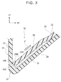
- a closed sectional shape is formed on the upper side edge portion side of the back door panel 16 by the front flange portion 34 of the outer panel 30 being overlapped with the front flange portion 24 of the inner panel 20 from above and joined to the front flange portion 24 by an adhesive, and a rear flange portion 36 of the outer panel 30 being overlapped with the rear flange portion 26 of the inner panel 20 from the inside (the inside of the closed section) and joined to the rear flange portion 26 by an adhesive G (see FIG. 3 ).
- the back window glass 18 is joined by a urethane adhesive Gu to an upper surface of the front flange portion 34 and an upper surface of the outer panel main body 32 of the outer panel 30. Also, an upper end portion of the front flange portion 24 of the inner panel 20 is abutting against an inside surface of the back window glass 18.
- the outer panel 30 functions as a first panel of the invention
- the inner panel 20 functions as a second panel of the invention. Therefore, the rear flange portion 36 functions as a first flange portion, and the rear flange portion 26 functions as a second flange portion.
- the vehicle body rear side of the inner panel main body 22 is arranged extending in a direction intersecting an input direction of a load F that will be described later. Therefore, in order to arrange the rear flange portion 26 along the input direction of the load F that will be described later, the rear flange portion 26 is formed by the vehicle body rear side end portion of the inner panel main body 22 being curved at an acute angle toward the vehicle body rear upper side. Also, the curved corner is a curved portion 28, and a tip end portion (tip end surface) 36A of the rear flange portion 36 of the outer panel 30 is abutting against an inside surface (a surface inside the closed section) 28A of the curved portion 28.
- the tip end portion 36A of the rear flange portion 36 of the outer panel 30 is a flat surface that is orthogonal to the extending direction of the rear flange portion 36, and the inside surface 28A of the curved portion 28 is also a flat surface that is orthogonal to the extending direction of the rear flange portion 36. Therefore, the tip end portion 36A of the rear flange portion 36 of the outer panel 30 contacts the inside surface 28A of the curved portion 28 via a surface, the inside surface 28A being an abutting portion.
- An edge line portion 36B on the vehicle body front side of the tip end portion 36A of the rear flange portion 36 is restricted to a position on the rear flange portion 26 side by an edge line portion 28B that extends in the vehicle width direction at the vehicle body front side end portion of the inside surface 28A of the curved portion 28.
- the tip end portion 36A of the rear flange portion 36 is able to effectively restricted from moving in a direction opposite the rear flange portion 26 side, i.e., the edge line portion 28B of the curved portion 28 serves as a position restricting portion for the tip end portion 36A of the rear flange portion 36.
- a vehicle body rear side portion of the tip end portion 36A of the rear flange portion 36 is formed having an arc-shaped cross-section.
- the inner panel 20 on both the left and right side edge portion sides of the back door panel 16 has an inner panel main body 23 that is formed having a generally L-shaped cross-section and extends in the vehicle body front-rear direction, an outer flange portion 25 formed by a vehicle width direction outside end portion of the inner panel main body 23 being curved toward the vehicle width direction outside, and an inner flange portion 27 formed by a vehicle width direction inside end portion of the inner panel main body 23 being curved toward the vehicle body upper side.
- a ball joint 56 to which one end portion of a damper, not shown, is attached is fastened to a vehicle width direction outside portion of the inner panel main body 23. More specifically, a through-hole 23A for ball joint fastening is formed in a vehicle width direction outside portion of the inner panel main body 23, and the cylindrical collar member 40 that has the flange portion 40A is fitted into this through-hole 23A.
- the metal retainer 42 that has the weld nut 44 and the through-hole 42A that is coaxially communicated with the through-hole 40B in the collar member 40 is provided inside the closed section of the inner panel main body 23. Therefore, the ball joint 56 is fastened to the inner panel main body 23 by a threaded portion 58 of the ball joint 56 being inserted through the through-hole 40B in the collar member 40 and the through-hole 42A in the retainer 42, and screwed into the weld nut 44.
- a weather strip 60 provided on the vehicle body 12 side elastically deforms and contacts the vehicle width direction inside portion of the inner panel main body 23 with a predetermined pressure. That is, the inner panel 20 is pressed toward the vehicle body upper side by the elastic restoring force of the elastically deformed weather strip 60.
- the outer panel 30 on both the left and right side edge portion sides of the back door panel 16 has an outer panel main body 33 that has a generally L-shaped cross-section and extends in the vehicle body front-rear direction, an outer flange portion 35 that is formed on a vehicle width direction outside end portion of the outer panel main body 33, and an inner flange portion 37 formed by a vehicle width direction inside end portion of the outer panel main body 33 being curved toward the vehicle body lower side.
- a closed sectional shape is formed on both the left and right side edge portion sides of the back door panel 16 by the outer flange portion 35 of the outer panel 30 being overlapped from above with the outer flange portion 25 of the inner panel 20 and joined to the outer flange portion 25 by an adhesive, and the inner flange portion 37 of the outer panel 30 being overlapped from the inside (inside the closed section) with the inner flange portion 27 of the inner panel 20 and joined to the inner flange portion 27 by the adhesive G (see FIG. 5 ).
- the back window glass 18 is joined by the urethane adhesive Gu to an upper surface of the outer flange portion 35 and an upper surface of the outer panel main body 33 of the outer panel 30. Also, a water stopping lip 62 is provided between the back window glass 18 and the vehicle width direction outside end portion of the outer flange portion 35 of the outer panel 30.
- the outer panel 30 functions as a first panel of the invention
- the inner panel 20 functions as the second panel of the invention. Therefore, the inner flange portion 37 functions as the first flange portion, and the inner flange portion 27 functions as the second flange portion.
- the vehicle width direction inside of the inner panel main body 23 is arranged extending in a direction intersecting the input direction of a load F that will be described later. Therefore, in order to arrange the inner flange portion 27 along the input direction of the load F that will be described later, the inner flange portion 27 is formed by the vehicle width direction inside end portion of the inner panel main body 23 being curved at a substantially right angle toward the vehicle body upper side.
- the curved corner is a curved portion 29, and a tip end portion (a tip end surface) 37A of the inner flange portion 37 of the outer panel 30 abuts against an inside surface (a surface on the inside the closed section) 29A of this curved portion 29.
- the tip end portion 37A of the inner flange portion 37 of the outer panel 30 is a flat surface that is orthogonal to the extending direction of the inner flange portion 37, and the inside surface 29A of the curved portion 29 is also a flat surface that is orthogonal to the extending direction of the inner flange portion 37. Therefore, the tip end portion 37A of the inner flange portion 37 of the outer panel 30 contacts the inside surface 29A of the curved portion 29 via a surface, the inside surface 29A being an abutting portion.
- a protruding portion 29B that protrudes in the input direction of the load F that will be described later is integrally formed on the inside surface 29A of the curved portion 29.
- An edge line portion 37B on the vehicle width direction outside of the tip end portion 37A of the inner flange portion 37 is restricted to a position on the inner flange portion 27 side by an edge line portion 29C on the vehicle width direction inside of this protruding portion 29B.
- the tip end portion 37A of the inner flange portion 37 is able to be effectively restricted from moving in a direction opposite the inner flange portion 27 side, i.e., the edge line portion 29C of the protruding portion 29B serves as a position restricting portion for the tip end portion 37A of the inner flange portion 37.
- a vehicle width direction inside portion of the tip end portion 37A of the inner flange portion 37 is formed having an arc-shaped cross-section.
- shearing force in the input direction of the load F is applied to the joint between the rear flange portion 26 of the inner panel 20 and the rear flange portion 36 of the outer panel 30. That is, shearing force in the input direction of the load F is applied to the adhesive G that joins the rear flange portion 26 and the rear flange portion 36 together. If the load F that is input here becomes equal to or greater than this shearing force, the rear flange portion 26 and the rear flange portion 36 may peel apart.
- the tip end portion 36A of the rear flange portion 36 of the outer panel 30 is abutting against the inside surface 28A (the abutting portion) of the curved portion 28 of the inner panel 20. Therefore, the load F that is relatively input to the inner panel 20 from the outer panel 30 is transmitted from the tip end portion 36A of the rear flange portion 36 of the outer panel 30 to the curved portion 28 of the inner panel 20 and distributed.
- the tip end portion 36A of the rear flange portion 36 and the inside surface 28A of the curved portion 28 are both flat surfaces, so the transmission efficiency of this load F is able to be improved. Accordingly, a load F equal to or greater than the shearing force is less apt to be input to the adhesive G that joins the rear flange portion 26 and the rear flange portion 36 together, and as a result, the rear flange portion 26 and the rear flange portion 36 are able to be inhibited or prevented from peeling apart.
- the inside surface 28A against which the tip end portion 36A of the rear flange portion 36 abuts is formed on the curved portion 28 that curves in a direction intersecting the input direction of the load F. Therefore, the rigidity of this inside surface 28A is able to be better ensured (i.e., improved). Also, the edge line portion 28B (the position restricting portion) that restricts the position of the tip end portion 36A (the edge line portion 36B) of the rear flange portion 36 is formed on the curved portion 28, so the rear flange portion 36 is able to be even better inhibited or prevented from peeling away from the rear flange portion 26.
- both the left and right side edge portion sides of the back door panel 16 are also the same. That is, when the resin back door 14 is firmly closed, pressure is applied to the inner panel 20 from the vehicle body lower side by the weather strip 60 on both the left and right side edge portion sides of the back door panel 16. That is, the load F (see FIG. 5 ) is relatively input from the outer panel 30 to the inner panel 20, the position of which is restricted by the weather strip 60. In other words, the load F is relatively input between the inner panel 20 and the outer panel 30.
- shearing force in the input direction of the load F is applied to the joint between the inner flange portion 27 of the inner panel 20 and the inner flange portion 37 of the outer panel 30. That is, shearing force in the input direction of the load F is applied to the adhesive G that joins the inner flange portion 27 and the inner flange portion 37 together. If the load F that is input here becomes equal to or greater than this shearing force, the inner flange portion 27 and the inner flange portion 37 may peel apart.
- the tip end portion 37A of the inner flange portion 37 of the outer panel 30 is abutting against the inside surface 29A (the abutting portion) of the curved portion 29 of the inner panel 20. Therefore, the load F that is relatively input to the inner panel 20 from the outer panel 30 is transmitted from the tip end portion 37A of the inner flange portion 37 of the outer panel 30 to the curved portion 29 of the inner panel 20 and distributed.
- the tip end portion 37A of the inner flange portion 37 and the inside surface 29A of the curved portion 29 are both flat surfaces, so the transmission efficiency of this load F is able to be improved. Accordingly, a load F equal to or greater than the shearing force is less apt to be input to the adhesive G that joins the inner flange portion 27 and the inner flange portion 37 together, and as a result, the inner flange portion 27 and the inner flange portion 37 are able to be inhibited or prevented from peeling apart.
- the inside surface 29A against which the tip end portion 37A of the inner flange portion 37 abuts is formed on the curved portion 29 that curves in a direction intersecting the input direction of the load F. Therefore, the rigidity of this inside surface 29A is able to be better ensured (i.e., improved). Also, the edge line portion 29C (the protruding portion 29B / the position restricting portion) that restricts the position of the tip end portion 37A (the edge line portion 37B) of the inner flange portion 37 is formed on the curved portion 29, so the tip end portion 37A of the inner flange portion 37 is able to be effectively restricted to the inner flange portion 27 side.
- the tip end portion 37A of the inner flange portion 37 is able to be effectively restricted from moving toward the side opposite the inner flange portion 27 side, so the inner flange portion 37 is able to be even better inhibited or prevented from peeling away from the inner flange portion 27.
- the manner in which the rear flange portion 26 of the inner panel 20 and the rear flange portion 36 of the outer panel 30 on the upper side edge portion side of the back door panel 16 overlap is the opposite that in the first example embodiment. That is, the rear flange portion 26 of the inner panel 20 overlaps the rear flange portion 36 of the outer panel 30 from the inside (the inside the closed section), and is joined to the rear flange portion 36 by the adhesive G.
- the joining structure between the rear flange portion 26 of the inner panel 20 and the rear flange portion 36 of the outer panel 30 on the upper side edge portion side of the back door panel 16 will be described.
- the inner panel 20 functions as the first panel of the invention
- the outer panel 30 functions as the second panel of the invention. Therefore, the rear flange portion 26 functions as the first flange portion, and the rear flange portion 36 functions as the second flange portion.
- the vehicle body lower side (rear side) of the outer panel main body 32 is arranged extending in a direction intersecting the input direction of the load F. Therefore, in order to arrange the rear flange portion 36 along the input direction of the load F, the rear flange portion 36 is formed by the vehicle body lower side (rear side) end portion of the outer panel main body 32 being curved at an obtuse angle toward the vehicle body front lower side.
- the curved corner is a curved portion 38, and a tip end portion (tip end surface) 26A of the rear flange portion 26 of the inner panel 20 is abutting against a protruding portion 38A that is provided protruding on an inside surface (a surface inside the closed section) of this curved portion 38.
- the tip end portion 26A of the rear flange portion 26 of the inner panel 20 is a flat surface that is orthogonal to the extending direction of the rear flange portion 26, and a flat surface portion 38B that is orthogonal to the extending direction of the rear flange portion 26 is also formed on the protruding portion 38A of the curved portion 38. Therefore, the tip end portion 26A of the rear flange portion 26 of the inner panel 20 contacts the flat surface portion 38B of the protruding portion 38A of the curved portion 38 via a surface, the flat surface portion 38B being an abutting portion.
- the load F that is relatively input from the inner panel 20, the position of which is restricted by the weather strip 60, to the outer panel 30 is transmitted from the tip end portion 26A of the rear flange portion 26 of the inner panel 20 to the protruding portion 38A (the curved portion 38) of the outer panel 30 and distributed.
- a load F equal to or greater than the shearing force is less apt to be input to the adhesive G that joins the rear flange portion 26 and the rear flange portion 36 together, and as a result, the rear flange portion 26 and the rear flange portion 36 are able to be inhibited or prevented from peeling apart.
- the vehicle body rear side portion of the tip end portion 26A of the rear flange portion 26 is formed having an arc-shaped cross-section.
- the manner in which the inner flange portion 27 of the inner panel 20 and the inner flange portion 37 of the outer panel 30 on both the left and right side edge portion sides of the back door panel 16 overlap is opposite that in the first example embodiment. That is, the inner flange portion 27 of the inner panel 20 overlaps the inner flange portion 37 of the outer panel 30 from the inside (the inside the closed section), and is joined to the inner flange portion 37 by the adhesive G.
- the inner flange portion 27 of the inner panel 20 functions as the first panel of the invention
- the outer panel 30 functions as the second panel of the invention. Therefore, the inner flange portion 27 functions as the first flange portion, and the inner flange portion 37 functions as the second flange portion.
- the vehicle width direction inside of the outer panel main body 33 is arranged extending in a direction that intersects the input direction of the load F. Therefore, in order to arrange the inner flange portion 37 along the input direction of the load F, the inner flange portion 37 is formed by the vehicle width direction inside end portion of the outer panel main body 33 being curved at an obtuse angle downward toward the vehicle width direction outside. Also, the curved corner is a curved portion 39, and a tip end portion (tip end surface) 27A of the inner flange portion 27 of the inner panel 20 is abutting against a protruding portion 39A that is provided protruding on an inside surface (a surface inside the closed section) of this curved portion 39.
- the tip end portion 27A of the inner flange portion 27 of the inner panel 20 is a flat surface that is orthogonal to the extending direction of the inner flange portion 27, and a flat surface portion 39B that is orthogonal to the extending direction of the inner flange portion 27 is also formed on the protruding portion 39A of the curved portion 39. Therefore, the tip end portion 27A of the inner flange portion 27 of the inner panel 20 contacts the flat surface portion 39B of the protruding portion 39A of the curved portion 39 via a surface, the flat surface portion 39B being an abutting portion.
- the load F that is relatively input from the inner panel 20, the position of which is restricted by the weather strip 60, to the outer panel 30 is transmitted from the tip end portion 27A of the inner flange portion 27 of the inner panel 20 to the protruding portion 39A (the curved portion 39) of the outer panel 30 and distributed.
- a load F equal to or greater than the shearing force is less apt to be input to the adhesive G that joins the inner flange portion 27 and the inner flange portion 37 together, and as a result, the inner flange portion 27 and the inner flange portion 37 are able to be inhibited or prevented from peeling apart.
- the vehicle body rear side portion of the tip end portion 27A of the inner flange portion 27 is formed having an arc-shaped cross-section.
- the panel structure 10 according to these example embodiments is described based on the drawings, but the panel structure 10 according to these example embodiments is not limited to the drawings. That is, appropriate design modifications are also possible without departing from the scope of the invention.
- the inner panel 20 and the outer panel 30 are not limited to being made of fiber reinforced resin material (FRP).
- the structure is such that the load F is able to be efficiently transmitted to the inside surface 28A and 29A of the curved portion 28 and 29 that is a flat surface
- the flat surface portion 38B and 39B of the curved portion 38 and 39 the tip end portion 26A and 36A of the rear flange portion 26 and 36, and the tip end portion 27A and 37A of the inner flange portion 27 and 37 do not have to each be a flat surface.
- the edge line portion 28B and 29C as the position restricting portion does not have to be formed on the curved portion 28 and 29.
- the panel structure 10 according to the example embodiments is not limited to a structure that is applied to the vehicle resin back door 14.
Abstract
A panel structure (10) is provided with a first panel (30) that is made of resin and has a first flange portion (36), and a second panel (20) that is made of resin and has a second flange portion (26) that overlaps the first flange portion (36) and is joined to the first flange portion by an adhesive, and an abutting portion (28A) that abuts against a tip end portion (36A) of the first flange portion (36), the second panel (20) forming a closed sectional shape with the first panel (30).
Description
- The invention relates to a panel structure.
- Japanese Patent Application Publication
JP 2006-341760 A - However, when a load in the shearing direction is input to a joint by an adhesive between one panel and the other panel, the joint may peel apart if the load becomes equal to or greater than the shearing stress.
- Therefore, the invention thus provides a panel structure capable of inhibiting peeling at a joint formed by an adhesive between one panel and another panel, even if a load of equal to or greater than a shearing stress is input to the joint.
- Thus, one aspect of the invention relates to a panel structure that includes a first panel that is made of resin and has a first flange portion; and a second panel that is made of resin, the second panel having a second flange portion and an abutting portion, the second flange portion being overlapped with the first flange portion and joined to the first flange portion by an adhesive, the abutting portion abutting against a tip end portion of the first flange portion so that the second panel forms a closed sectional shape with the first panel. In other words, the panel structure has a closed sectional shape formed by the first panel and the second panel. There is no gap between first panel and the second panel.
- According to this panel structure, even if a load equal to or greater than the shearing force is input to the joint between the first flange portion and the second flange portion, this load is transmitted from the tip end portion of the first flange portion to the abutting portion of the second panel and distributed. Therefore, the joint between the first flange portion and the second flange portion is inhibited from peeling apart.
- In the panel structure described above, the first flange portion may be arranged along an input direction of a load.
- Also, in the panel structure described above, either or both of the tip end portion of the first flange portion and the abutting portion may be or have a flat surface. Therefore, the transmission efficiency of a load from the tip end portion of the first flange portion to the abutting portion of the second panel improves.
- Also, in the panel structure described above, the second panel may have a curved portion, and the abutting portion may be formed on the curved portion that is curved. Therefore, the rigidity of the abutting portion improves.
- In the panel structure described above, the curved portion may be curved in order to arrange the second flange portion along an input direction of a load.
- Also, in the panel structure described above, a position restricting portion that restricts a position of the tip end portion of the first flange portion to the second flange portion side may be formed on the curved portion. Therefore, the first flange portion is even better inhibited or prevented from peeling away from the second flange portion.
- In the panel structure described above, the position restricting portion may restrict the tip end portion of the first flange portion from moving in a direction opposite the second flange portion side.
- Also, in the panel structure described above, the position restricting portion may be a protruding portion that protrudes from the curved portion. Therefore, the position of the tip end portion of the first flange portion is effectively restricted to the second flange portion side.
- In the panel structure described above, the protruding portion may protrude in an input direction of a load.
- In the panel structure described above, the position restricting portion may be an edge line portion that extends in a vehicle width direction at a vehicle body front side end portion of an inside surface of the curved portion.
- Also, in the panel structure described above, the first panel may be one of an inner panel and an outer panel that forms a back door panel of a vehicle resin back door, and the second panel may be the other of the inner panel and the outer panel. Therefore, even if a load of equal to or greater than the shearing force is input to the joining portion between the inner panel and the outer panel when the resin back door is firmly closed or the like, peeling at this joint is inhibited.
- In the panel structure described above, the load is a load relatively input between the second panel and the first panel.
- Features, advantages, and technical and industrial significance of exemplary embodiments of the invention will be described below with reference to the accompanying drawings, in which like numerals denote like elements, and wherein:
-
FIG. 1 is a perspective view of a vehicle resin back door provided with a panel structure according to example embodiments of the invention; -
FIG. 2 is a sectional view taken along line X - X inFIG. 1 , of a panel structure according to a first example embodiment of the invention; -
FIG. 3 is a partial enlarged sectional view ofFIG. 2 ; -
FIG. 4 is a sectional view taken along line Y - Y inFIG. 1 , of the panel structure according to the first example embodiment; -
FIG. 5 is a partial enlarged sectional view ofFIG. 2 ; -
FIG. 6 is an enlarged sectional view corresponding toFIG. 3 , of a panel structure according to a second example embodiment of the invention; and -
FIG. 7 is an enlarged sectional view corresponding toFIG. 5 , of the panel structure according to the second example embodiment. - Hereinafter, example embodiments of the invention will be described in detail with reference to the accompanying drawings. To simplify the description, a case will be described in which a
panel structure 10 in the example embodiments is taken as an example. Therefore, in the drawings, arrow UP indicates a vehicle body upward direction, arrow RE indicates a vehicle body rearward direction, and arrow OUT indicates a vehicle width direction outside. Also, in the description below, unless otherwise specified, the directions of upper, lower, front, rear, and left and right indicate upper and lower in a vehicle body vertical direction, front and rear in a vehicle body front-rear direction, and left and right in a vehicle body left-right direction (vehicle width direction). - First, a first example embodiment of the invention will be described. As shown in
FIG. 1 , aresin back door 14 provided on a rear portion of a vehicle body 12 (seeFIGS. 2 and4 ) includes aback door panel 16, and aback window glass 18 provided closing off an opening 16A formed in an upper portion of theback door panel 16. - As shown in
FIGS. 2 and4 , theback door panel 16 has aninner panel 20 and anouter panel 30 that form a closed sectional shape by being joined together. Theinner panel 20 and theouter panel 30 are made of a fiber reinforced resin material (FRP) such as carbon fiber reinforced resin material (CFRP). - As shown in
FIG. 2 , theinner panel 20 on an upper side edge portion side of theback door panel 16 has an inner panelmain body 22 that extends in the vehicle width direction, afront flange portion 24 that is formed by a vehicle body front side end portion of the inner panelmain body 22 being curved toward the vehicle body upper side, and arear flange portion 26 formed by a vehicle body rear side end portion of the inner panelmain body 22 being curved toward the vehicle body rear upper side. - The inner panel
main body 22 is bolt fastened to ahinge portion 50 on thevehicle body 12 side. More specifically, a hinge portionmain body 52 is fastened and fixed to thevehicle body 12 by afastener 48 such as a bolt or rivet, and aplate portion 54 having a through-hole 54A for bolt-fastening is able to be rotatably supported on an upper end portion of the hinge portionmain body 52. - Also, a through-
hole 22A for bolt-fastening is also formed in the inner panelmain body 22, and acylindrical collar member 40 having aflange portion 40A is fitted into this through-hole 22A. Also, ametal retainer 42 that has aweld nut 44 and a through-hole 42A that is coaxially communicated with a through-hole 40B in thecollar member 40, is provided inside a closed section of the inner panelmain body 22. - Therefore, the
inner panel 20 is fastened to thehinge portion 50 by theflange portion 40A of thecollar member 40 provided on the inner panelmain body 22 being overlapped with theplate portion 54 of thehinge portion 50, abolt 46 being inserted through the through-hole 54A in theplate portion 54, the through-hole 40B in thecollar member 40, and the through-hole 42A in theretainer 42, and being screwed into theweld nut 44. - Also, a
recessed portion 21 that is recessed toward the vehicle body upper side is formed farther to the vehicle body rear side than the through-hole 22A and farther toward the vehicle body front side than therear flange portion 26, in the inner panelmain body 22. When the resin backdoor 14 is closed, aweather strip 60 provided on thevehicle body 12 side elastically deforms and contacts abottom wall 21A of therecessed portion 21 with a predetermined pressure. That is, theinner panel 20 is pressed toward the vehicle body upper side by the elastic restoring force of the elasticallydeformed weather strip 60. - Also, as shown in
FIG. 2 , theouter panel 30 on the upper side edge portion side of theback door panel 16 has an outer panelmain body 32 that is formed having a general L-shaped cross-section and extends in the vehicle width direction, afront flange portion 34 that is formed on a vehicle body front side end portion of the outer panelmain body 32, and arear flange portion 36 formed by a vehicle body lower side (rear side) end portion of the outer panelmain body 32 that is curved toward the vehicle lower side being curved at an obtuse angle toward the vehicle body front lower side. - Therefore, a closed sectional shape is formed on the upper side edge portion side of the
back door panel 16 by thefront flange portion 34 of theouter panel 30 being overlapped with thefront flange portion 24 of theinner panel 20 from above and joined to thefront flange portion 24 by an adhesive, and arear flange portion 36 of theouter panel 30 being overlapped with therear flange portion 26 of theinner panel 20 from the inside (the inside of the closed section) and joined to therear flange portion 26 by an adhesive G (seeFIG. 3 ). - The
back window glass 18 is joined by a urethane adhesive Gu to an upper surface of thefront flange portion 34 and an upper surface of the outer panelmain body 32 of theouter panel 30. Also, an upper end portion of thefront flange portion 24 of theinner panel 20 is abutting against an inside surface of theback window glass 18. - Here, a joining structure between the
rear flange portion 26 of theinner panel 20 and therear flange portion 36 of theouter panel 30 on the upper side edge portion side of theback door panel 16 will be described. InFIGS. 2 and3 , theouter panel 30 functions as a first panel of the invention, and theinner panel 20 functions as a second panel of the invention. Therefore, therear flange portion 36 functions as a first flange portion, and therear flange portion 26 functions as a second flange portion. - As shown in
FIGS. 2 and3 , the vehicle body rear side of the inner panelmain body 22 is arranged extending in a direction intersecting an input direction of a load F that will be described later. Therefore, in order to arrange therear flange portion 26 along the input direction of the load F that will be described later, therear flange portion 26 is formed by the vehicle body rear side end portion of the inner panelmain body 22 being curved at an acute angle toward the vehicle body rear upper side. Also, the curved corner is acurved portion 28, and a tip end portion (tip end surface) 36A of therear flange portion 36 of theouter panel 30 is abutting against an inside surface (a surface inside the closed section) 28A of thecurved portion 28. - More specifically, the
tip end portion 36A of therear flange portion 36 of theouter panel 30 is a flat surface that is orthogonal to the extending direction of therear flange portion 36, and theinside surface 28A of thecurved portion 28 is also a flat surface that is orthogonal to the extending direction of therear flange portion 36. Therefore, thetip end portion 36A of therear flange portion 36 of theouter panel 30 contacts theinside surface 28A of thecurved portion 28 via a surface, theinside surface 28A being an abutting portion. - An
edge line portion 36B on the vehicle body front side of thetip end portion 36A of therear flange portion 36 is restricted to a position on therear flange portion 26 side by anedge line portion 28B that extends in the vehicle width direction at the vehicle body front side end portion of theinside surface 28A of thecurved portion 28. In other words, thetip end portion 36A of therear flange portion 36 is able to effectively restricted from moving in a direction opposite therear flange portion 26 side, i.e., theedge line portion 28B of thecurved portion 28 serves as a position restricting portion for thetip end portion 36A of therear flange portion 36. - Also, a vehicle body rear side portion of the
tip end portion 36A of therear flange portion 36 is formed having an arc-shaped cross-section. As a result, the joint area on thetip end portion 36A side of therear flange portion 36 of theouter panel 30 with respect to therear flange portion 26 of theinner panel 20 increases, so joint strength on thetip end portion 36A side with respect to the curved portion 28 (insidesurface 28A) is greater. - On the other hand, as shown in
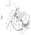
FIG. 4 , theinner panel 20 on both the left and right side edge portion sides of theback door panel 16 has an inner panelmain body 23 that is formed having a generally L-shaped cross-section and extends in the vehicle body front-rear direction, anouter flange portion 25 formed by a vehicle width direction outside end portion of the inner panelmain body 23 being curved toward the vehicle width direction outside, and aninner flange portion 27 formed by a vehicle width direction inside end portion of the inner panelmain body 23 being curved toward the vehicle body upper side. - A ball joint 56 to which one end portion of a damper, not shown, is attached is fastened to a vehicle width direction outside portion of the inner panel
main body 23. More specifically, a through-hole 23A for ball joint fastening is formed in a vehicle width direction outside portion of the inner panelmain body 23, and thecylindrical collar member 40 that has theflange portion 40A is fitted into this through-hole 23A. - Then, the
metal retainer 42 that has theweld nut 44 and the through-hole 42A that is coaxially communicated with the through-hole 40B in thecollar member 40 is provided inside the closed section of the inner panelmain body 23. Therefore, the ball joint 56 is fastened to the inner panelmain body 23 by a threadedportion 58 of the ball joint 56 being inserted through the through-hole 40B in thecollar member 40 and the through-hole 42A in theretainer 42, and screwed into theweld nut 44. - Then, when the resin back
door 14 is closed, aweather strip 60 provided on thevehicle body 12 side elastically deforms and contacts the vehicle width direction inside portion of the inner panelmain body 23 with a predetermined pressure. That is, theinner panel 20 is pressed toward the vehicle body upper side by the elastic restoring force of the elasticallydeformed weather strip 60. - Also, as shown in
FIG. 4 , theouter panel 30 on both the left and right side edge portion sides of theback door panel 16 has an outer panelmain body 33 that has a generally L-shaped cross-section and extends in the vehicle body front-rear direction, anouter flange portion 35 that is formed on a vehicle width direction outside end portion of the outer panelmain body 33, and aninner flange portion 37 formed by a vehicle width direction inside end portion of the outer panelmain body 33 being curved toward the vehicle body lower side. - Therefore, a closed sectional shape is formed on both the left and right side edge portion sides of the
back door panel 16 by theouter flange portion 35 of theouter panel 30 being overlapped from above with theouter flange portion 25 of theinner panel 20 and joined to theouter flange portion 25 by an adhesive, and theinner flange portion 37 of theouter panel 30 being overlapped from the inside (inside the closed section) with theinner flange portion 27 of theinner panel 20 and joined to theinner flange portion 27 by the adhesive G (seeFIG. 5 ). - The
back window glass 18 is joined by the urethane adhesive Gu to an upper surface of theouter flange portion 35 and an upper surface of the outer panelmain body 33 of theouter panel 30. Also, awater stopping lip 62 is provided between theback window glass 18 and the vehicle width direction outside end portion of theouter flange portion 35 of theouter panel 30. - Here, the joining structure between the
inner flange portion 27 of theinner panel 20 and theinner flange portion 37 of theouter panel 30 on both the left and right side edge portion sides of theback door panel 16 will be described. InFIGS. 4 and5 , theouter panel 30 functions as a first panel of the invention, and theinner panel 20 functions as the second panel of the invention. Therefore, theinner flange portion 37 functions as the first flange portion, and theinner flange portion 27 functions as the second flange portion. - As shown in
FIGS. 4 and5 , the vehicle width direction inside of the inner panelmain body 23 is arranged extending in a direction intersecting the input direction of a load F that will be described later. Therefore, in order to arrange theinner flange portion 27 along the input direction of the load F that will be described later, theinner flange portion 27 is formed by the vehicle width direction inside end portion of the inner panelmain body 23 being curved at a substantially right angle toward the vehicle body upper side. The curved corner is acurved portion 29, and a tip end portion (a tip end surface) 37A of theinner flange portion 37 of theouter panel 30 abuts against an inside surface (a surface on the inside the closed section) 29A of thiscurved portion 29. - More specifically, the
tip end portion 37A of theinner flange portion 37 of theouter panel 30 is a flat surface that is orthogonal to the extending direction of theinner flange portion 37, and theinside surface 29A of thecurved portion 29 is also a flat surface that is orthogonal to the extending direction of theinner flange portion 37. Therefore, thetip end portion 37A of theinner flange portion 37 of theouter panel 30 contacts theinside surface 29A of thecurved portion 29 via a surface, theinside surface 29A being an abutting portion. - Also, a protruding
portion 29B that protrudes in the input direction of the load F that will be described later is integrally formed on theinside surface 29A of thecurved portion 29. Anedge line portion 37B on the vehicle width direction outside of thetip end portion 37A of theinner flange portion 37 is restricted to a position on theinner flange portion 27 side by anedge line portion 29C on the vehicle width direction inside of this protrudingportion 29B. In other words, thetip end portion 37A of theinner flange portion 37 is able to be effectively restricted from moving in a direction opposite theinner flange portion 27 side, i.e., theedge line portion 29C of the protrudingportion 29B serves as a position restricting portion for thetip end portion 37A of theinner flange portion 37. - Also, a vehicle width direction inside portion of the
tip end portion 37A of theinner flange portion 37 is formed having an arc-shaped cross-section. As a result, the joint area on thetip end portion 37A side of theinner flange portion 37 of theouter panel 30 with respect to theinner flange portion 27 of theinner panel 20 increases, so the joint strength on thetip end portion 37A side with respect to the curved portion 29 (insidesurface 29A) is greater. - Next, the operation of the vehicle resin back
door 14 provided with thepanel structure 10 according to the first example embodiment having a structure such as that described above will be described. - When the resin back
door 14 is firmly closed, pressure is applied from the vehicle body lower side to the recessedportion 21 of theinner panel 20 by theweather strip 60, on the upper side edge portion side of theback door panel 16. That is, a load F (seeFIG. 3 ) is relatively input from theouter panel 30 to theinner panel 20, the position of which is restricted by theweather strip 60. In other words, the load F is relatively input between theinner panel 20 and theouter panel 30. - When this occurs, shearing force in the input direction of the load F is applied to the joint between the
rear flange portion 26 of theinner panel 20 and therear flange portion 36 of theouter panel 30. That is, shearing force in the input direction of the load F is applied to the adhesive G that joins therear flange portion 26 and therear flange portion 36 together. If the load F that is input here becomes equal to or greater than this shearing force, therear flange portion 26 and therear flange portion 36 may peel apart. - However, in this example embodiment, the
tip end portion 36A of therear flange portion 36 of theouter panel 30 is abutting against theinside surface 28A (the abutting portion) of thecurved portion 28 of theinner panel 20. Therefore, the load F that is relatively input to theinner panel 20 from theouter panel 30 is transmitted from thetip end portion 36A of therear flange portion 36 of theouter panel 30 to thecurved portion 28 of theinner panel 20 and distributed. - In particular, in this example embodiment, the
tip end portion 36A of therear flange portion 36 and theinside surface 28A of thecurved portion 28 are both flat surfaces, so the transmission efficiency of this load F is able to be improved. Accordingly, a load F equal to or greater than the shearing force is less apt to be input to the adhesive G that joins therear flange portion 26 and therear flange portion 36 together, and as a result, therear flange portion 26 and therear flange portion 36 are able to be inhibited or prevented from peeling apart. - The
inside surface 28A against which thetip end portion 36A of therear flange portion 36 abuts is formed on thecurved portion 28 that curves in a direction intersecting the input direction of the load F. Therefore, the rigidity of thisinside surface 28A is able to be better ensured (i.e., improved). Also, theedge line portion 28B (the position restricting portion) that restricts the position of thetip end portion 36A (theedge line portion 36B) of therear flange portion 36 is formed on thecurved portion 28, so therear flange portion 36 is able to be even better inhibited or prevented from peeling away from therear flange portion 26. - Moreover, both the left and right side edge portion sides of the
back door panel 16 are also the same. That is, when the resin backdoor 14 is firmly closed, pressure is applied to theinner panel 20 from the vehicle body lower side by theweather strip 60 on both the left and right side edge portion sides of theback door panel 16. That is, the load F (seeFIG. 5 ) is relatively input from theouter panel 30 to theinner panel 20, the position of which is restricted by theweather strip 60. In other words, the load F is relatively input between theinner panel 20 and theouter panel 30. - When this occurs, shearing force in the input direction of the load F is applied to the joint between the
inner flange portion 27 of theinner panel 20 and theinner flange portion 37 of theouter panel 30. That is, shearing force in the input direction of the load F is applied to the adhesive G that joins theinner flange portion 27 and theinner flange portion 37 together. If the load F that is input here becomes equal to or greater than this shearing force, theinner flange portion 27 and theinner flange portion 37 may peel apart. - However, in this example embodiment, the
tip end portion 37A of theinner flange portion 37 of theouter panel 30 is abutting against theinside surface 29A (the abutting portion) of thecurved portion 29 of theinner panel 20. Therefore, the load F that is relatively input to theinner panel 20 from theouter panel 30 is transmitted from thetip end portion 37A of theinner flange portion 37 of theouter panel 30 to thecurved portion 29 of theinner panel 20 and distributed. - In particular, in this example embodiment, the
tip end portion 37A of theinner flange portion 37 and theinside surface 29A of thecurved portion 29 are both flat surfaces, so the transmission efficiency of this load F is able to be improved. Accordingly, a load F equal to or greater than the shearing force is less apt to be input to the adhesive G that joins theinner flange portion 27 and theinner flange portion 37 together, and as a result, theinner flange portion 27 and theinner flange portion 37 are able to be inhibited or prevented from peeling apart. - The
inside surface 29A against which thetip end portion 37A of theinner flange portion 37 abuts is formed on thecurved portion 29 that curves in a direction intersecting the input direction of the load F. Therefore, the rigidity of thisinside surface 29A is able to be better ensured (i.e., improved). Also, theedge line portion 29C (the protrudingportion 29B / the position restricting portion) that restricts the position of thetip end portion 37A (theedge line portion 37B) of theinner flange portion 37 is formed on thecurved portion 29, so thetip end portion 37A of theinner flange portion 37 is able to be effectively restricted to theinner flange portion 27 side. In other words, thetip end portion 37A of theinner flange portion 37 is able to be effectively restricted from moving toward the side opposite theinner flange portion 27 side, so theinner flange portion 37 is able to be even better inhibited or prevented from peeling away from theinner flange portion 27. - Next, a second example embodiment of the invention will be described. Portions in this second example embodiment that are equivalent to portions in the first example embodiment described above will be denoted by like reference characters and detailed descriptions (including common operation) of those portions will be omitted as appropriate.
- As shown in
FIG. 6 , in this second example embodiment, the manner in which therear flange portion 26 of theinner panel 20 and therear flange portion 36 of theouter panel 30 on the upper side edge portion side of theback door panel 16 overlap is the opposite that in the first example embodiment. That is, therear flange portion 26 of theinner panel 20 overlaps therear flange portion 36 of theouter panel 30 from the inside (the inside the closed section), and is joined to therear flange portion 36 by the adhesive G. - Here, the joining structure between the
rear flange portion 26 of theinner panel 20 and therear flange portion 36 of theouter panel 30 on the upper side edge portion side of theback door panel 16 will be described. InFIG. 6 , theinner panel 20 functions as the first panel of the invention, and theouter panel 30 functions as the second panel of the invention. Therefore, therear flange portion 26 functions as the first flange portion, and therear flange portion 36 functions as the second flange portion. - As shown in
FIG. 6 , the vehicle body lower side (rear side) of the outer panelmain body 32 is arranged extending in a direction intersecting the input direction of the load F. Therefore, in order to arrange therear flange portion 36 along the input direction of the load F, therear flange portion 36 is formed by the vehicle body lower side (rear side) end portion of the outer panelmain body 32 being curved at an obtuse angle toward the vehicle body front lower side. Also, the curved corner is acurved portion 38, and a tip end portion (tip end surface) 26A of therear flange portion 26 of theinner panel 20 is abutting against a protrudingportion 38A that is provided protruding on an inside surface (a surface inside the closed section) of thiscurved portion 38. - More specifically, the
tip end portion 26A of therear flange portion 26 of theinner panel 20 is a flat surface that is orthogonal to the extending direction of therear flange portion 26, and aflat surface portion 38B that is orthogonal to the extending direction of therear flange portion 26 is also formed on the protrudingportion 38A of thecurved portion 38. Therefore, thetip end portion 26A of therear flange portion 26 of theinner panel 20 contacts theflat surface portion 38B of the protrudingportion 38A of thecurved portion 38 via a surface, theflat surface portion 38B being an abutting portion. - Therefore, when the resin back
door 14 is firmly closed, the load F that is relatively input from theinner panel 20, the position of which is restricted by theweather strip 60, to theouter panel 30 is transmitted from thetip end portion 26A of therear flange portion 26 of theinner panel 20 to the protrudingportion 38A (the curved portion 38) of theouter panel 30 and distributed. Thus, a load F equal to or greater than the shearing force is less apt to be input to the adhesive G that joins therear flange portion 26 and therear flange portion 36 together, and as a result, therear flange portion 26 and therear flange portion 36 are able to be inhibited or prevented from peeling apart. - In this way, in this second example embodiment in which the manner in which the
rear flange portion 26 of theinner panel 20 and therear flange portion 36 of theouter panel 30 at the upper side edge portion of theback door panel 16 overlap is the opposite that in the first example embodiment as well, operation and effects equivalent to those of the first example embodiment are able to be obtained. In this second example embodiment, the vehicle body rear side portion of thetip end portion 26A of therear flange portion 26 is formed having an arc-shaped cross-section. - Also, as shown in
FIG. 7 , in this second example embodiment, the manner in which theinner flange portion 27 of theinner panel 20 and theinner flange portion 37 of theouter panel 30 on both the left and right side edge portion sides of theback door panel 16 overlap is opposite that in the first example embodiment. That is, theinner flange portion 27 of theinner panel 20 overlaps theinner flange portion 37 of theouter panel 30 from the inside (the inside the closed section), and is joined to theinner flange portion 37 by the adhesive G. - Here, the joining structure between the
inner flange portion 27 of theinner panel 20 and theinner flange portion 37 of theouter panel 30 on both of the left and right side edge portion sides of theback door panel 16 will be described. InFIG. 7 , theinner panel 20 functions as the first panel of the invention, and theouter panel 30 functions as the second panel of the invention. Therefore, theinner flange portion 27 functions as the first flange portion, and theinner flange portion 37 functions as the second flange portion. - As shown in
FIG. 7 , the vehicle width direction inside of the outer panelmain body 33 is arranged extending in a direction that intersects the input direction of the load F. Therefore, in order to arrange theinner flange portion 37 along the input direction of the load F, theinner flange portion 37 is formed by the vehicle width direction inside end portion of the outer panelmain body 33 being curved at an obtuse angle downward toward the vehicle width direction outside. Also, the curved corner is acurved portion 39, and a tip end portion (tip end surface) 27A of theinner flange portion 27 of theinner panel 20 is abutting against a protrudingportion 39A that is provided protruding on an inside surface (a surface inside the closed section) of thiscurved portion 39. - More specifically, the
tip end portion 27A of theinner flange portion 27 of theinner panel 20 is a flat surface that is orthogonal to the extending direction of theinner flange portion 27, and aflat surface portion 39B that is orthogonal to the extending direction of theinner flange portion 27 is also formed on the protrudingportion 39A of thecurved portion 39. Therefore, thetip end portion 27A of theinner flange portion 27 of theinner panel 20 contacts theflat surface portion 39B of the protrudingportion 39A of thecurved portion 39 via a surface, theflat surface portion 39B being an abutting portion. - Therefore, when the resin back
door 14 is firmly closed, the load F that is relatively input from theinner panel 20, the position of which is restricted by theweather strip 60, to theouter panel 30 is transmitted from thetip end portion 27A of theinner flange portion 27 of theinner panel 20 to the protrudingportion 39A (the curved portion 39) of theouter panel 30 and distributed. Thus, a load F equal to or greater than the shearing force is less apt to be input to the adhesive G that joins theinner flange portion 27 and theinner flange portion 37 together, and as a result, theinner flange portion 27 and theinner flange portion 37 are able to be inhibited or prevented from peeling apart. - In this way, in this second example embodiment in which the manner in which the
inner flange portion 27 of theinner panel 20 and theinner flange portion 37 of theouter panel 30 at both the left and right side edge portions of theback door panel 16 overlap is the opposite that in the first example embodiment as well, operation and effects equivalent to those of the first example embodiment are able to be obtained. In this second example embodiment, the vehicle body rear side portion of thetip end portion 27A of theinner flange portion 27 is formed having an arc-shaped cross-section. - Heretofore, the
panel structure 10 according to these example embodiments is described based on the drawings, but thepanel structure 10 according to these example embodiments is not limited to the drawings. That is, appropriate design modifications are also possible without departing from the scope of the invention. For example, theinner panel 20 and theouter panel 30 are not limited to being made of fiber reinforced resin material (FRP). - Also, as long as the structure is such that the load F is able to be efficiently transmitted to the
inside surface curved portion flat surface portion curved portion tip end portion rear flange portion tip end portion inner flange portion - Also, even if the load F is input, as long as the joined state between the
rear flange portion inner flange portion edge line portion curved portion panel structure 10 according to the example embodiments is not limited to a structure that is applied to the vehicle resin backdoor 14.
Claims (12)
- A panel structure (10) comprising:a first panel (30; 20), preferably made of resin, having a first flange portion (36, 37; 26, 27); anda second panel (20; 30), preferably made of resin, having a second flange portion (26, 27; 36, 37) and an abutting portion (28A, 29A; 38B, 39B), the second flange portion (26, 27; 36, 37) being overlapped with the first flange portion (36, 37; 26, 27) and joined to the first flange portion (36, 37; 26, 27) by an adhesive (G), the abutting portion (28A, 29A; 38B, 39B) abutting against a tip end portion (36A, 37A; 26A, 27A) of the first flange portion (36, 37; 26, 27) so that the second panel forms a closed sectional shape with the first panel.
- The panel structure (10) according to claim 1, wherein
the first flange portion (36, 37; 26, 27) is arranged along an input direction of a load. - The panel structure (10) according to claim 1 or 2, wherein
either or both of the tip end portion (36A, 37A; 26A, 27A) of the first flange portion (36, 37; 26, 27) and the abutting portion (28A, 29A; 38B, 39B) has a flat surface. - The panel structure (10) according to any one of claims 1 to 3, wherein
the second panel (20; 30) has a curved portion (28, 29; 38, 39), and the abutting portion (28A, 29A; 38B, 39B) is formed on the curved portion (28, 29; 38, 39). - The panel structure (10) according to claim 4, wherein
the curved portion (28, 29; 38, 39) is curved in order to arrange the second flange portion (26, 27; 36, 37) along an input direction of a load. - The panel structure (10) according to claim 4 or 5, wherein
a position restricting portion (28B, 29C) that restricts a position of the tip end portion (36A, 37A) of the first flange portion (36, 37) to the second flange portion side is formed on the curved portion (28, 29). - The panel structure (10) according to claim 6, wherein
the position restricting portion (28B, 29C) restricts the tip end portion (36A, 37A) of the first flange portion (36, 37) from moving in a direction opposite the second flange portion side. - The panel structure (10) according to claim 6 or 7, wherein
the position restricting portion (29B) is a protruding portion that protrudes from the curved portion (29). - The panel structure (10) according to claim 8, wherein
the protruding portion (29B) protrudes in an input direction of a load. - The panel structure (10) according to claim 6 or 7, wherein
the position restricting portion (28B, 29C) is an edge line portion that extends in a vehicle width direction at a vehicle body front side end portion of an inside surface of the curved portion (28, 29). - The panel structure (10) according to any one of claims 1 to 10, wherein
the first panel (30; 20) is one of an inner panel (20) and an outer panel (30) that form a back door panel (16) of a vehicle resin back door (14), and the second panel (20; 30) is the other of the inner panel (20) and the outer panel (30). - The panel structure (10) according to any one of claims 2, 5, and 9, wherein
the load is a load relatively input between the second panel (20; 30) and the first panel (30; 20).
Applications Claiming Priority (1)
| Application Number | Priority Date | Filing Date | Title |
|---|---|---|---|
| JP2014253304A JP2016113021A (en) | 2014-12-15 | 2014-12-15 | Panel structure |
Publications (1)
| Publication Number | Publication Date |
|---|---|
| EP3034339A1 true EP3034339A1 (en) | 2016-06-22 |
Family
ID=55129398
Family Applications (1)
| Application Number | Title | Priority Date | Filing Date |
|---|---|---|---|
| EP15199904.2A Withdrawn EP3034339A1 (en) | 2014-12-15 | 2015-12-14 | Panel structure |
Country Status (4)
| Country | Link |
|---|---|
| US (1) | US9994092B2 (en) |
| EP (1) | EP3034339A1 (en) |
| JP (1) | JP2016113021A (en) |
| CN (1) | CN105691169A (en) |
Cited By (1)
| Publication number | Priority date | Publication date | Assignee | Title |
|---|---|---|---|---|
| EP3722128A1 (en) * | 2019-04-11 | 2020-10-14 | Compagnie Plastic Omnium | Tailgate box assembly and improved tailgate skin |
Families Citing this family (9)
| Publication number | Priority date | Publication date | Assignee | Title |
|---|---|---|---|---|
| JP6206387B2 (en) * | 2014-12-15 | 2017-10-04 | トヨタ自動車株式会社 | Joining method for vehicle back door |
| JP6323417B2 (en) * | 2015-09-04 | 2018-05-16 | トヨタ自動車株式会社 | Vehicle back door structure |
| JP6322181B2 (en) * | 2015-12-16 | 2018-05-09 | 本田技研工業株式会社 | Tailgate structure |
| DE102016215093B4 (en) * | 2016-08-12 | 2021-01-07 | Bayerische Motoren Werke Aktiengesellschaft | Motor vehicle |
| WO2018110021A1 (en) * | 2016-12-14 | 2018-06-21 | 本田技研工業株式会社 | Door structure |
| JP2018161945A (en) * | 2017-03-24 | 2018-10-18 | 株式会社豊田自動織機 | Vehicular back door |
| JP6959131B2 (en) * | 2017-12-21 | 2021-11-02 | トヨタ自動車株式会社 | Vehicle resin back door |
| US11826967B2 (en) * | 2019-03-26 | 2023-11-28 | Nissan Motor Co., Ltd. | Method of manufacturing closed cross-section structural member |
| US11964548B2 (en) * | 2021-06-08 | 2024-04-23 | Nissan North America, Inc. | Reinforcements and support brackets for vehicle doors |
Citations (4)
| Publication number | Priority date | Publication date | Assignee | Title |
|---|---|---|---|---|
| FR2548600A1 (en) * | 1983-07-05 | 1985-01-11 | Renault | Motor vehicle bodywork with composite tailgate |
| EP0266514A2 (en) * | 1986-11-05 | 1988-05-11 | Ford-Werke Aktiengesellschaft | Plastic sandwich body element for a motor vehicle |
| JP2006341760A (en) | 2005-06-09 | 2006-12-21 | Nissan Motor Co Ltd | Panel structure, and manufacturing method and manufacturing apparatus for the panel structure |
| EP2036750A2 (en) * | 2007-09-07 | 2009-03-18 | REHAU AG + Co | Window arrangement for a motor vehicle |
Family Cites Families (15)
| Publication number | Priority date | Publication date | Assignee | Title |
|---|---|---|---|---|
| JP2977035B1 (en) * | 1998-06-26 | 1999-11-10 | 東北ムネカタ株式会社 | Heat-welded structure of thermoplastic resin molded product |
| EP1097797B1 (en) * | 1999-11-02 | 2004-02-04 | TOHOKU MUNEKATA Co., Ltd. | Joining thermoplastic cases and covers by fusion |
| US6439649B1 (en) * | 2001-02-15 | 2002-08-27 | Dow Global Technologies Inc. | Pickup truck box |
| JP4300860B2 (en) * | 2003-04-25 | 2009-07-22 | マツダ株式会社 | Automotive back door seal structure |
| JP4202360B2 (en) * | 2005-12-28 | 2008-12-24 | 本田技研工業株式会社 | Vehicle door structure |
| JP5004227B2 (en) * | 2007-09-27 | 2012-08-22 | キャタピラー エス エー アール エル | Door panel |
| US8087720B2 (en) * | 2008-09-23 | 2012-01-03 | GM Global Technology Operations LLC | Vehicle closure panel assembly and method |
| JP4712854B2 (en) * | 2008-10-23 | 2011-06-29 | 本田技研工業株式会社 | Rear door structure |
| JP2012136166A (en) * | 2010-12-27 | 2012-07-19 | Daihatsu Motor Co Ltd | Automobile panel |
| US8632118B2 (en) * | 2011-08-29 | 2014-01-21 | GM Global Technology Operations LLC | Body panel assembly and a method for manufacturing a body panel assembly |
| JP5867062B2 (en) | 2011-12-20 | 2016-02-24 | トヨタ自動車株式会社 | Resin panel joint structure |
| ITMI20120958A1 (en) * | 2012-06-04 | 2013-12-05 | Politec Polimeri Tecnici Sa | ASSEMBLY OF ALVEOLAR PANELS FOR ROOFS AND WALLS |
| JP6051644B2 (en) * | 2012-07-20 | 2016-12-27 | マツダ株式会社 | Plastic door structure |
| JP5942858B2 (en) * | 2013-01-07 | 2016-06-29 | トヨタ自動車株式会社 | Resin back door structure for vehicles |
| JP2014205491A (en) * | 2014-08-08 | 2014-10-30 | ダイハツ工業株式会社 | Vehicle door assembly method |
-
2014
- 2014-12-15 JP JP2014253304A patent/JP2016113021A/en active Pending
-
2015
- 2015-12-08 US US14/962,638 patent/US9994092B2/en active Active
- 2015-12-14 CN CN201510927150.1A patent/CN105691169A/en active Pending
- 2015-12-14 EP EP15199904.2A patent/EP3034339A1/en not_active Withdrawn
Patent Citations (4)
| Publication number | Priority date | Publication date | Assignee | Title |
|---|---|---|---|---|
| FR2548600A1 (en) * | 1983-07-05 | 1985-01-11 | Renault | Motor vehicle bodywork with composite tailgate |
| EP0266514A2 (en) * | 1986-11-05 | 1988-05-11 | Ford-Werke Aktiengesellschaft | Plastic sandwich body element for a motor vehicle |
| JP2006341760A (en) | 2005-06-09 | 2006-12-21 | Nissan Motor Co Ltd | Panel structure, and manufacturing method and manufacturing apparatus for the panel structure |
| EP2036750A2 (en) * | 2007-09-07 | 2009-03-18 | REHAU AG + Co | Window arrangement for a motor vehicle |
Cited By (2)
| Publication number | Priority date | Publication date | Assignee | Title |
|---|---|---|---|---|
| EP3722128A1 (en) * | 2019-04-11 | 2020-10-14 | Compagnie Plastic Omnium | Tailgate box assembly and improved tailgate skin |
| FR3094923A1 (en) * | 2019-04-11 | 2020-10-16 | Compagnie Plastic Omnium | Upgraded Tailgate Box and Tailgate Skin Kit |
Also Published As
| Publication number | Publication date |
|---|---|
| JP2016113021A (en) | 2016-06-23 |
| CN105691169A (en) | 2016-06-22 |
| US20160167495A1 (en) | 2016-06-16 |
| US9994092B2 (en) | 2018-06-12 |
Similar Documents
| Publication | Publication Date | Title |
|---|---|---|
| EP3034339A1 (en) | Panel structure | |
| US7083224B2 (en) | Front fender structure | |
| US9623731B2 (en) | Vehicular resin back door structure | |
| US9783239B2 (en) | Structure for side part of body of vehicle | |
| US9713949B2 (en) | Vehicle body structure | |
| US9511680B2 (en) | Vehicle battery mounting structure | |
| EP2979909A1 (en) | Vehicle resin back door structure | |
| US10399520B2 (en) | Vehicle body structure | |
| JP2015120447A (en) | Vehicle side part structure | |
| JP2016215680A (en) | Vehicle structure | |
| US10280656B2 (en) | Door handle apparatus for vehicle | |
| US10167021B2 (en) | Vehicular resin panel structure and luggage door | |
| EP3050731A1 (en) | Weather-strip-equipped vehicle body structure | |
| US10967717B2 (en) | Door structure | |
| JP6555116B2 (en) | Vehicle door structure | |
| US11110780B2 (en) | Assembly having two roof frame elements, roof frame and a vehicle roof of a motor vehicle | |
| JP6019085B2 (en) | Carpet fixing structure | |
| JP4765676B2 (en) | Body side structure | |
| JP5694793B2 (en) | Vehicle door structure | |
| JP2020152341A (en) | Vehicle body side structure | |
| JP2017074830A (en) | Door opening structure of vehicle | |
| US10442371B2 (en) | Attachment member for wire guiding device | |
| JP5649442B2 (en) | Parts mounting structure | |
| JP2013099997A (en) | Vehicle bottom structure | |
| JP2020040472A (en) | Vehicle spoiler attachment structure |
Legal Events
| Date | Code | Title | Description |
|---|---|---|---|
| PUAI | Public reference made under article 153(3) epc to a published international application that has entered the european phase |
Free format text: ORIGINAL CODE: 0009012 |
|
| 17P | Request for examination filed |
Effective date: 20151214 |
|
| AK | Designated contracting states |
Kind code of ref document: A1 Designated state(s): AL AT BE BG CH CY CZ DE DK EE ES FI FR GB GR HR HU IE IS IT LI LT LU LV MC MK MT NL NO PL PT RO RS SE SI SK SM TR |
|
| AX | Request for extension of the european patent |
Extension state: BA ME |
|
| STAA | Information on the status of an ep patent application or granted ep patent |
Free format text: STATUS: THE APPLICATION HAS BEEN WITHDRAWN |
|
| 18W | Application withdrawn |
Effective date: 20180515 |