EP3034191B2 - Dispositif et procédé de fabrication d'un élément de profil longitudinal - Google Patents
Dispositif et procédé de fabrication d'un élément de profil longitudinal Download PDFInfo
- Publication number
- EP3034191B2 EP3034191B2 EP14199470.7A EP14199470A EP3034191B2 EP 3034191 B2 EP3034191 B2 EP 3034191B2 EP 14199470 A EP14199470 A EP 14199470A EP 3034191 B2 EP3034191 B2 EP 3034191B2
- Authority
- EP
- European Patent Office
- Prior art keywords
- strip
- embossing
- longitudinal
- sections
- profiled
- Prior art date
- Legal status (The legal status is an assumption and is not a legal conclusion. Google has not performed a legal analysis and makes no representation as to the accuracy of the status listed.)
- Active
Links
- 238000004519 manufacturing process Methods 0.000 title claims description 11
- 238000004049 embossing Methods 0.000 claims description 69
- 238000009966 trimming Methods 0.000 claims description 29
- 238000000034 method Methods 0.000 claims description 27
- 238000005520 cutting process Methods 0.000 claims description 16
- 238000005259 measurement Methods 0.000 claims description 6
- 238000005096 rolling process Methods 0.000 claims description 4
- 238000003698 laser cutting Methods 0.000 claims description 3
- 239000002184 metal Substances 0.000 claims description 3
- 238000011144 upstream manufacturing Methods 0.000 claims description 3
- 238000009751 slip forming Methods 0.000 claims description 2
- 230000001105 regulatory effect Effects 0.000 claims 3
- 238000010924 continuous production Methods 0.000 description 3
- 239000000463 material Substances 0.000 description 3
- 238000004080 punching Methods 0.000 description 2
- 229910000831 Steel Inorganic materials 0.000 description 1
- 238000005452 bending Methods 0.000 description 1
- 230000005540 biological transmission Effects 0.000 description 1
- 230000001419 dependent effect Effects 0.000 description 1
- 238000003825 pressing Methods 0.000 description 1
- 238000000926 separation method Methods 0.000 description 1
- 238000007493 shaping process Methods 0.000 description 1
- 239000010959 steel Substances 0.000 description 1
- XLYOFNOQVPJJNP-UHFFFAOYSA-N water Substances O XLYOFNOQVPJJNP-UHFFFAOYSA-N 0.000 description 1
- 230000003313 weakening effect Effects 0.000 description 1
Images


Classifications
-
- B—PERFORMING OPERATIONS; TRANSPORTING
- B21—MECHANICAL METAL-WORKING WITHOUT ESSENTIALLY REMOVING MATERIAL; PUNCHING METAL
- B21D—WORKING OR PROCESSING OF SHEET METAL OR METAL TUBES, RODS OR PROFILES WITHOUT ESSENTIALLY REMOVING MATERIAL; PUNCHING METAL
- B21D5/00—Bending sheet metal along straight lines, e.g. to form simple curves
- B21D5/06—Bending sheet metal along straight lines, e.g. to form simple curves by drawing procedure making use of dies or forming-rollers, e.g. making profiles
- B21D5/08—Bending sheet metal along straight lines, e.g. to form simple curves by drawing procedure making use of dies or forming-rollers, e.g. making profiles making use of forming-rollers
- B21D5/083—Bending sheet metal along straight lines, e.g. to form simple curves by drawing procedure making use of dies or forming-rollers, e.g. making profiles making use of forming-rollers for obtaining profiles with changing cross-sectional configuration
-
- B—PERFORMING OPERATIONS; TRANSPORTING
- B21—MECHANICAL METAL-WORKING WITHOUT ESSENTIALLY REMOVING MATERIAL; PUNCHING METAL
- B21D—WORKING OR PROCESSING OF SHEET METAL OR METAL TUBES, RODS OR PROFILES WITHOUT ESSENTIALLY REMOVING MATERIAL; PUNCHING METAL
- B21D35/00—Combined processes according to or processes combined with methods covered by groups B21D1/00 - B21D31/00
-
- B—PERFORMING OPERATIONS; TRANSPORTING
- B21—MECHANICAL METAL-WORKING WITHOUT ESSENTIALLY REMOVING MATERIAL; PUNCHING METAL
- B21D—WORKING OR PROCESSING OF SHEET METAL OR METAL TUBES, RODS OR PROFILES WITHOUT ESSENTIALLY REMOVING MATERIAL; PUNCHING METAL
- B21D5/00—Bending sheet metal along straight lines, e.g. to form simple curves
- B21D5/06—Bending sheet metal along straight lines, e.g. to form simple curves by drawing procedure making use of dies or forming-rollers, e.g. making profiles
-
- B—PERFORMING OPERATIONS; TRANSPORTING
- B23—MACHINE TOOLS; METAL-WORKING NOT OTHERWISE PROVIDED FOR
- B23K—SOLDERING OR UNSOLDERING; WELDING; CLADDING OR PLATING BY SOLDERING OR WELDING; CUTTING BY APPLYING HEAT LOCALLY, e.g. FLAME CUTTING; WORKING BY LASER BEAM
- B23K26/00—Working by laser beam, e.g. welding, cutting or boring
- B23K26/0093—Working by laser beam, e.g. welding, cutting or boring combined with mechanical machining or metal-working covered by other subclasses than B23K
-
- B—PERFORMING OPERATIONS; TRANSPORTING
- B21—MECHANICAL METAL-WORKING WITHOUT ESSENTIALLY REMOVING MATERIAL; PUNCHING METAL
- B21D—WORKING OR PROCESSING OF SHEET METAL OR METAL TUBES, RODS OR PROFILES WITHOUT ESSENTIALLY REMOVING MATERIAL; PUNCHING METAL
- B21D22/00—Shaping without cutting, by stamping, spinning, or deep-drawing
- B21D22/20—Deep-drawing
- B21D22/26—Deep-drawing for making peculiarly, e.g. irregularly, shaped articles
Definitions
- the invention relates to a device and a method for producing an elongate profile part, in which a profiled strip is produced from a flat strip, in particular metal strip, by rolling and the profiled strip is embossed in sections, as a result of which at least one longitudinal section of the profiled strip is opposite to at least one other longitudinal section is offset in a direction perpendicular to the longitudinal extent of the profiled strip, and in which method the strip is trimmed in such a way that after embossing the offset longitudinal sections have different cross-sections.
- the trimming step requires, in particular, a high degree of accuracy in the positioning and support of the profile part relative to a separating tool in order to be able to ensure the dimensional accuracy of the elongate profile part. Manufacturing tolerances when trimming therefore have an increased influence on the reproducibility of the process.
- the embossing tools for offsetting the longitudinal sections require comparatively high embossing forces, which reduces the energy efficiency of the method and, together with increased tool wear, increases the method costs. In this way it is also necessary to accept a weakening of the stability of the elongate profile part due to material removal from the profiled strip.
- the invention has therefore set itself the task of simplifying a method for producing an elongate profile part and thus improving its reproducibility.
- the process should be more energy-efficient and cheaper to use and enable the production of highly resilient, elongated profile parts.
- the comparatively complex process step of trimming known from the prior art can be considerably simplified.
- Handling of the method can be further simplified if the flat strip is trimmed by dividing, in particular punching, or by removing, in particular laser cutting.
- the embossing step can be additionally simplified in terms of handling if the flat and trimmed strip is profiled in sections by rolling at least in the longitudinal extent to form a hat profile.
- the flanges of the hat profile can namely serve as bearing surfaces for a hold-down device in order to further support the embossing.
- the strip is preferably profiled to form a hat profile exclusively in its untrimmed longitudinal areas, in order not to jeopardize the embossing of the profiled strip in sections to create the offset longitudinal section.
- the method for producing a profiled part with flanges running longitudinally can be accelerated.
- the profiled band can be embossed in several embossing steps. In this way, it is also possible to protect the embossing tool - which means that profile parts can be produced more reliably and subsequently more cheaply using the process.
- flanges running at least in regions over the longitudinal sections are embossed during the final embossing, a particularly straight flange termination on the longitudinal sides of the profile part can be achieved in a simple manner. In this way, it is easier to simply match the flanges of the offset longitudinal sections to one another on the pre-embossed strip during final embossing. This can also stabilize the shaping through previous embossing steps and thus lead to a dimensionally accurate profile part, which can improve the reproducibility of the process.
- the dimensional accuracy of the elongate profile part can be further improved if, according to the invention, the profiled band is subjected to tensile stress on both sides in the longitudinal extension during embossing. For example, the risk of waves forming in the profile part can thus be reduced.
- a continuous process can be created if several elongated profile parts are cut off from the strip that has been trimmed and embossed several times. Cutting off here can preferably enable a chip-free separation.
- the elongate profile member is severed to provide a continuous process using an endless belt.
- the method according to the invention can significantly improve the dimensional accuracy of the profile part if the course of the cutting line is changed when trimming the strip to compensate for a deviation of a measured actual geometry from a predetermined target geometry on the elongated profile part.
- the invention has also set itself the task of changing the design of a device for producing an elongate profile part from a flat strip of the type described at the outset in such a way that it can produce a profile part stably, quickly and inexpensively.
- the invention solves the problem set with regard to the device by the features of claim 11.
- the trimming device is arranged upstream of the profiling device in the direction of passage of the strip, the resulting reduced material can result in a reduction in force in the subsequent devices for forming, namely on the profiling or embossing device, and the stability of the device can thus be improved.
- extremely precise trimming can be possible with a flat strip, which can enable profile parts to be produced with a precise shape.
- the trimming device is also designed for trimming the strip in such a way that the offset longitudinal sections have different cross sections due to the embossing of the trimmed and profiled strip, the device can be designed to be particularly compact and inexpensive.
- a continuously operating device can be created if the device has a cutting device provided in the direction of passage of the strip after the embossing device for cutting off profile parts from the strip.
- the risk of creating waviness on the profile part during embossing can be significantly reduced if the embossing device has at least two hold-down devices with which the band can be clamped during embossing and thus a longitudinal pull can be produced on both sides.
- This can be solved in a structurally comparatively simple manner in that either the lower or upper tool of the embossing tool interacts with the hold-down device to clamp the profiled band during embossing with the aid of the other tool that can be moved between the two hold-down devices.
- the accuracy of the device can be increased if the device has a control device and a measuring device which is data-connected to the control device and with which measurement data on the actual geometry of the elongate profile part are recorded, the control device depending on a comparison of the measurement data with specified data for the target Geometry on the elongate profile part is data-connected to the trimming device for changing the cutting line of the trimming device in order to compensate for deviations in the actual geometry from the predetermined target geometry on the elongate profile part.
- an elongate profile part 1 produced with the method according to the invention is shown, for example.
- This elongated profile part 1 essentially has two different longitudinal sections 2, 3 with a U-shaped profile - according to the Figures 2 and 3 shown.
- the middle longitudinal section 2 is offset in comparison to its adjacent longitudinal sections 3 in a direction perpendicular to the longitudinal extent 4 of the profile part 1 .
- the maximum offset 5 in the direction perpendicular to the longitudinal extension 4 of the profile part 1 is located.
- the bottom 7 of the longitudinal section 3 adjoins the longitudinal sections 2 starting from a central floor course parallel to the floors 6 of the longitudinal section 2 via floor courses that are inclined to the floors 6 of the longitudinal section 2 .
- This floor course shown for the longitudinal section 3 is, for example, to stand, any floor course, For example, rectangular, V-shaped, etc. is conceivable - it being sufficient for the invention if only two mutually offset longitudinal sections 2 and 3 are provided on the band 14 .
- the in 2 illustrated cross section 8 of the longitudinal sections 2 to the in 3 illustrated cross section 9 of the longitudinal section 3 at least in the amount of the respective legs 10, 11 different.
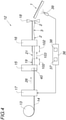
- This elongated profile part 1 is using a post 4 Device 12 shown schematically generated.
- a strip 14, namely steel strip is unwound from a coil 13, roll-profiled, embossed in sections, trimmed and cut to length - in order to produce a plurality of elongated profile parts 1 in a continuous process.
- the device 12 has a profiling device 15 , an embossing device 16 , a trimming device 17 and a cutting device 18 .
- the strip 14 is profiled with the profiling device 15 in order to essentially give the elongate profile part 1 the cross-sectional shape.
- the embossing device 16 arranged after the profiling device 15 in the direction of passage 26 of the strip 14, the longitudinal sections 2, 3 are produced in the profiled strip 14, which are offset in a direction perpendicular to the longitudinal extension 4 of the profiled strip 14.
- the strip 14 is subjected to a cutting process at least in sections along at least one of its longitudinal edges 19, 20. As in figure 5 As can be seen, this takes place for the band 14 along an open cutting line 21, 22.
- the cutting device 18 is used to cut off a plurality of elongated profile parts 1 from the endless band 14.
- the flat strip 14 is trimmed before the profiling device 15 .
- the trimming device 17 arranged upstream of the profiling device 15 in the direction of passage 26 of the strip 14, the flat strip 14 is now trimmed before profiling in such a way that the offset longitudinal sections 2, 3 have different cross-sections 8, 9 as a result of the embossing of the trimmed and profiled strip 14 .
- This trimming of the flat strip 14 with an open cutting line 21, 22 can be done by dividing, for example punching and/or cutting out etc., or by removing, for example by laser cutting and/or water cutting etc., which has not been shown in detail.
- the flat band 14 thus has a contour course along its longitudinal band edges 19 , 20 which provides less band material in the offset longitudinal section 3 .
- the reason for this is, on the one hand, to reduce the expenditure of force during embossing, and also to create the different cross section 9 in this longitudinal section 3 after embossing.
- no plastic changes in shape of the strip 14 have to be taken into account when trimming the flat strip 14, which makes the method significantly easier to handle and therefore also more reproducible. This makes it easier to maintain high manufacturing accuracy on the elongated profile part 1 that is produced.
- the elongated profile part 1 is constructed symmetrically as seen in the longitudinal extent 4, because the flat strip 14 is trimmed at the two longitudinal edges 19, 20 of the strip in the same way.
- the flat and trimmed strip 14 is only hinted at in 4 rollers 40 shown are roll-profiled in order to produce the basic shape of the elongate profile part 1 inexpensively by this continuous bending process.
- the flat and trimmed band 14 is profiled in sections in the longitudinal extension 4 to form a hat profile 23 or omega profile, namely in its untrimmed longitudinal areas 102.
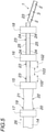
- the embossing device 16 completes the hat profile 23 extending in the longitudinal extension 4 of the band 14 - specifically in that the profiled band 14 is continuously formed into a hat profile during embossing in the longitudinal extent 4, primarily in the trimmed areas 103 of the band 14.
- the embossing of the profiled band 14 takes place in several stages.
- the embossing device 16 has several presses with interacting tools one after the other—which has not been shown in detail.
- the effort required for the respective embossing stages of the embossing device 16 is further reduced according to the invention.
- This is particularly the case when flanges 24, 25 running at least in regions over the longitudinal sections 2, 3 are embossed on the pre-embossed band 14 during the final embossing.
- the exemplary embodiment provides for the profiled band 14 to be loaded on both sides in the transverse direction of the band 14 under tension in the longitudinal extension 4 in order to prevent any ripples running over the flanges 24, 25. In this way, the flanges 24, 25 achieve a particularly uniform termination of the profile.
- the embossing device 16 is shown in more detail, which has two hold-down devices 27, 28 and an embossing tool 29 with an upper tool 30 and a lower tool 31.
- the hold-down devices 27, 28 cooperate with the upper tool 30 to clamp the band 14 during stamping, as shown below Figures 6 and 7a can be seen.
- the upper tool 30 presses the band 14 onto the hold-down devices 27 or 28 and holds the band 14 firmly in place.
- the strip 14 is now embossed in sections--as already described above.
- the hold-down device 27, 28 consists of two jaws 34, 35 that can be opened and closed transversely to the direction of passage 26 on a guide 32, 33, as compared between Figures 7a and 7b can be seen.
- the moving in and out of the upper tool 30 into the hold-down device 27 can also be seen.
- the embossing of the profiled band 14 can take place in several embossing steps.
- the embossing device 16 can have several embossing stages in succession, as in 6 shown, associated with hold-down device 27, 28 and embossing tool 29, which has not been shown in detail.
- the device 12 is supplemented with a control device 36 in order to improve or guarantee the dimensional accuracy of the profile part 1 produced with it.
- the control device has, for example, an I controller (integrating controller, I element) in order to exclude control deviations and thus ensure complete compensation of a deviation of the actual geometry on the elongated profile part 1 from the specified target geometry on the elongated profile part 1.
- I controller integrating controller, I element
- Other controllers or standard controllers with P, PI, PD and PID behavior are conceivable.
- the target geometry on the elongate profile part is specified for the control device 36 in the form of data 37 .
- This data 37 is compared with measurement data 38 which is recorded from the finished profile part 1 by a measurement device 39 which is connected to the control device 36 for the purpose of transmitting data.
- This measuring device 39 is in the 4 designed as a camera for recording video data.
- Other measuring devices 39 are conceivable, for example a laser scanner etc., in order to be able to record measuring data dependent on the actual geometry of the profile part 1 .
- a deviation that can take into account a predetermined manufacturing tolerance is compensated by the control device 36 in that the cutting line 21, 22 of the trimming device 14 is changed for at least one subsequent profile part.
- the control device 36 is connected to the trimming device 14 for the transmission of data, in order to further sew the actual geometry of not yet finished profile parts to the desired target geometry or to bring it into agreement therewith.
- Tolerances on the device 12 or manufacturing tolerances on the strip 14 can thus be taken into account or compensated for particularly quickly, which makes the method extremely reproducible and the device 12 stable.
Landscapes
- Engineering & Computer Science (AREA)
- Mechanical Engineering (AREA)
- Physics & Mathematics (AREA)
- Optics & Photonics (AREA)
- Plasma & Fusion (AREA)
- Shaping Metal By Deep-Drawing, Or The Like (AREA)
- Bending Of Plates, Rods, And Pipes (AREA)
- Shaping Of Tube Ends By Bending Or Straightening (AREA)
- Metal Rolling (AREA)
- Credit Cards Or The Like (AREA)
- Package Frames And Binding Bands (AREA)
Claims (13)
- Procédé pour la fabrication d'une pièce profilée allongée (1), dans lequel une bande (14) profilée est produite à partir d'une bande (14) plate, en particulier métallique, par laminage et la bande (14) profilée est estampée par parties, de sorte qu'au moins une partie longitudinale (3) de la bande (14) profilée est décalée par rapport à au moins une autre partie longitudinale (2) dans une direction perpendiculaire à la longueur (4) de la bande (14) profilée, et dans lequel la bande (14) est rognée de telle manière qu'après l'estampage, les parties longitudinales (2, 3) décalées l'une par rapport à l'autre présentent des sections (8, 9) différentes, caractérisé en ce que la bande (14) plate est rognée avant le profilage de telle manière que l'estampage de la bande (14) rognée et profilée donne aux parties longitudinales (2, 3) décalées l'une par rapport à l'autre des sections (8, 9) différentes, la bande (14) profilée étant soumise des deux côtés à une contrainte de traction dans sa longueur (4) lors de l'estampage.
- Procédé selon la revendication 1, caractérisé en ce que la bande (14) plate est rognée sur ses deux bords longitudinaux (19, 20), de préférence de la même manière.
- Procédé selon la revendication 1 ou 2, caractérisé en ce que la bande (14) plate est rognée par découpe, en particulier à l'emporte-pièce, ou par enlèvement de matière, en particulier par découpe au laser.
- Procédé selon la revendication 1, 2 ou 3, caractérisé en ce que la bande (14) plate et rognée est profilée par sections par laminage au moins dans sa longueur (4) pour former un profilé chapeau (23).
- Procédé selon la revendication 4, caractérisé en ce que la bande (14) est profilée exclusivement dans les zones non rognées (102) de sa longueur pour former un profilé chapeau (23).
- Procédé selon l'une des revendications 1 à 5, caractérisé en ce que la bande (14) profilée est déformée de façon continue lors de l'estampage dans sa longueur (4) pour former un profilé chapeau (23).
- Procédé selon l'une des revendications 1 à 6, caractérisé en ce que l'estampage de la bande (14) profilée est effectué en plusieurs étapes d'estampage.
- Procédé selon la revendication 7, caractérisé en ce que lors de l'estampage final, des brides (24, 25) s'étendant au moins par zones sur les parties longitudinales (2, 3) sont formées par estampage.
- Procédé selon l'une des revendications 1 à 8, caractérisé en ce que plusieurs pièces profilées allongées (1) sont découpées dans la bande (14) rognée plusieurs fois et estampée plusieurs fois.
- Procédé selon la revendication 9, caractérisé en ce qu'afin de compenser un écart d'une géométrie réelle mesurée par rapport à une géométrie de consigne, le trajet de la ligne de coupe (21, 22) sur la pièce profilée allongée (1) est modifié lors du rognage de la bande (14).
- Installation pour fabriquer une pièce profilée allongée (1) à partir d'une bande (14) plate avec un dispositif de profilage (15) qui comporte au moins un cylindre (40) pour profiler la bande (14) plate, avec un dispositif d'estampage (16) disposé après le dispositif de profilage (15) dans les sens de passage (26) de la bande, qui présente au moins un outil d'estampage (29) pour estamper au moins par zones la bande (14) profilée de telle manière qu'au moins une partie longitudinale (3) de la bande (14) profilée soit ainsi décalée par rapport à au moins une autre partie longitudinale (2) dans une direction perpendiculaire à la longueur de la bande (14) profilée, et avec un dispositif de rognage (17) qui est conçu pour rogner la bande (14) de telle manière qu'après l'estampage par le dispositif d'estampage (16), les parties longitudinales (2, 3) décalées l'une par rapport à l'autre présentent des sections (8, 9) différentes, caractérisée en ce que le dispositif de rognage (17) est disposé avant le dispositif de profilage (15) dans le sens de passage (26) de la bande (14) et conformé pour rogner la bande (14) de telle manière que l'estampage de la bande (14) rognée et profilée confère aux parties longitudinales (2, 3) décalées l'une par rapport à l'autre des sections (8, 9) différentes, dans lequel le dispositif d'estampage (16) ayant au moins deux organes de d'appui (27, 28) et en ce que l'outil supérieur ou l'outil inférieur (30 ou 31) de l'outil d'estampage (29) coopère avec l'organe d'appui (27, 28) pour pincer la bande (14) profilée à l'aide de l'autre outil (31 ou 30) qui peut être déplacé entre les deux organes d'appui (27, 28).
- Installation selon la revendication 11, caractérisée en ce qu'elle comporte un dispositif de recoupe (18) disposé après le dispositif d'estampage (16) dans le sens de passage (26) de la bande (14) pour découper des pièces profilées (1) dans la bande (14).
- Installation selon la revendication 11 ou 12, caractérisée en ce qu'elle comporte un dispositif de réglage (36) et un dispositif de mesure (39) en liaison de données avec le dispositif de réglage (36), avec lequel des données de mesure (38) sur la géométrie réelle de la pièce profilée allongée (1) sont recueillies, le dispositif de réglage (36) étant en liaison de données, en fonction d'une comparaison des données de mesure (38) avec des données prédéterminées (37) sur la géométrie de consigne de la pièce profilée allongée (1), avec le dispositif de recoupe (14) pour changer la ligne de coupe (21, 22) du dispositif de rognage (14), afin de compenser les déviations de la géométrie réelle par rapport à la géométrie de consigne spécifiée de la pièce profilée allongée (1).
Priority Applications (7)
| Application Number | Priority Date | Filing Date | Title |
|---|---|---|---|
| ES14199470T ES2623818T5 (es) | 2014-12-19 | 2014-12-19 | Dispositivo y procedimiento para la producción de una pieza perfilada alargada |
| PL14199470T PL3034191T5 (pl) | 2014-12-19 | 2014-12-19 | Urządzenie i sposób do wytwarzania podłużnej części profilowej |
| EP14199470.7A EP3034191B2 (fr) | 2014-12-19 | 2014-12-19 | Dispositif et procédé de fabrication d'un élément de profil longitudinal |
| PCT/EP2015/080895 WO2016097426A1 (fr) | 2014-12-19 | 2015-12-21 | Dispositif et procédé de fabrication d'un élément profilé allongé |
| US15/537,867 US11351586B2 (en) | 2014-12-19 | 2015-12-21 | Apparatus and method for producing an elongated profiled part |
| CA2970988A CA2970988C (fr) | 2014-12-19 | 2015-12-21 | Dispositif et procede de fabrication d'un element profile allonge |
| BR112017011123A BR112017011123A2 (pt) | 2014-12-19 | 2015-12-21 | dispositivo e método para a produção de uma peça de perfil alongada |
Applications Claiming Priority (1)
| Application Number | Priority Date | Filing Date | Title |
|---|---|---|---|
| EP14199470.7A EP3034191B2 (fr) | 2014-12-19 | 2014-12-19 | Dispositif et procédé de fabrication d'un élément de profil longitudinal |
Publications (3)
| Publication Number | Publication Date |
|---|---|
| EP3034191A1 EP3034191A1 (fr) | 2016-06-22 |
| EP3034191B1 EP3034191B1 (fr) | 2017-02-01 |
| EP3034191B2 true EP3034191B2 (fr) | 2022-01-26 |
Family
ID=52146265
Family Applications (1)
| Application Number | Title | Priority Date | Filing Date |
|---|---|---|---|
| EP14199470.7A Active EP3034191B2 (fr) | 2014-12-19 | 2014-12-19 | Dispositif et procédé de fabrication d'un élément de profil longitudinal |
Country Status (7)
| Country | Link |
|---|---|
| US (1) | US11351586B2 (fr) |
| EP (1) | EP3034191B2 (fr) |
| BR (1) | BR112017011123A2 (fr) |
| CA (1) | CA2970988C (fr) |
| ES (1) | ES2623818T5 (fr) |
| PL (1) | PL3034191T5 (fr) |
| WO (1) | WO2016097426A1 (fr) |
Families Citing this family (2)
| Publication number | Priority date | Publication date | Assignee | Title |
|---|---|---|---|---|
| DE102018115740A1 (de) * | 2018-06-29 | 2020-01-02 | Airbus Operations Gmbh | Verfahren zum Herstellen eines Querträgers für ein Fahrzeug sowie ein Querträger für ein Fahrzeug |
| CN111346985A (zh) * | 2020-03-14 | 2020-06-30 | 上海冀晟自动化成套设备有限公司 | 一种筒体激光焊接机及其使用方法 |
Citations (2)
| Publication number | Priority date | Publication date | Assignee | Title |
|---|---|---|---|---|
| EP1537922A1 (fr) † | 2003-12-04 | 2005-06-08 | HONDA MOTOR CO., Ltd. | Fabrication de profilés avec une section variable dans la direction longitudinale |
| EP2875877A1 (fr) † | 2013-11-05 | 2015-05-27 | Welser Profile Austria GmbH | Procédé de fabrication d'un profilé à section variable |
Family Cites Families (6)
| Publication number | Priority date | Publication date | Assignee | Title |
|---|---|---|---|---|
| US3119432A (en) * | 1961-05-15 | 1964-01-28 | Pullmax Ab | Sheet metal forming tools |
| US5237846A (en) * | 1990-08-16 | 1993-08-24 | Brooks Jr Barlow W | Method and apparatus for forming metal roll-formed parts |
| US5142894A (en) * | 1991-03-15 | 1992-09-01 | Contour Roll Company | Roll-forming method |
| DE10011755B4 (de) * | 2000-03-13 | 2005-05-25 | Peter Prof. Dr.-Ing. Dipl.-Wirtsch.-Ing. Groche | Verfahren und Vorrichtung zur Herstellung eines Profils mit über der Längsachse veränderlichem Querschnitt mittels Walzprofilieren |
| DE10210807A1 (de) | 2002-03-12 | 2003-10-02 | Kronenberg Profil Gmbh | Profilteil, Vorrichtung und Verfahren zu seiner Herstellung sowie Verwendung des Profilteils |
| DE102007059439B3 (de) | 2007-12-10 | 2009-04-02 | Data M Software Gmbh | Vorrichtung und Verfahren zum Kaltwalzprofilieren von Profilen mit veränderlicher Höhe |
-
2014
- 2014-12-19 PL PL14199470T patent/PL3034191T5/pl unknown
- 2014-12-19 EP EP14199470.7A patent/EP3034191B2/fr active Active
- 2014-12-19 ES ES14199470T patent/ES2623818T5/es active Active
-
2015
- 2015-12-21 US US15/537,867 patent/US11351586B2/en active Active
- 2015-12-21 CA CA2970988A patent/CA2970988C/fr not_active Expired - Fee Related
- 2015-12-21 BR BR112017011123A patent/BR112017011123A2/pt active Search and Examination
- 2015-12-21 WO PCT/EP2015/080895 patent/WO2016097426A1/fr active Application Filing
Patent Citations (2)
| Publication number | Priority date | Publication date | Assignee | Title |
|---|---|---|---|---|
| EP1537922A1 (fr) † | 2003-12-04 | 2005-06-08 | HONDA MOTOR CO., Ltd. | Fabrication de profilés avec une section variable dans la direction longitudinale |
| EP2875877A1 (fr) † | 2013-11-05 | 2015-05-27 | Welser Profile Austria GmbH | Procédé de fabrication d'un profilé à section variable |
Also Published As
| Publication number | Publication date |
|---|---|
| EP3034191A1 (fr) | 2016-06-22 |
| ES2623818T3 (es) | 2017-07-12 |
| PL3034191T5 (pl) | 2022-05-23 |
| CA2970988A1 (fr) | 2016-06-23 |
| US11351586B2 (en) | 2022-06-07 |
| ES2623818T5 (es) | 2022-05-17 |
| PL3034191T3 (pl) | 2017-08-31 |
| US20170348748A1 (en) | 2017-12-07 |
| EP3034191B1 (fr) | 2017-02-01 |
| BR112017011123A2 (pt) | 2017-12-26 |
| WO2016097426A1 (fr) | 2016-06-23 |
| CA2970988C (fr) | 2021-02-09 |
Similar Documents
| Publication | Publication Date | Title |
|---|---|---|
| DE4442269B4 (de) | Käfig für ein Rollenlager und Verfahren zu dessen Herstellung | |
| EP2701861B1 (fr) | Procédé et dispositif de fabrication de pièces embouties sans bride | |
| EP3020489B1 (fr) | Procédé et installation pour le raccordement de bandes métalliques | |
| EP2313216B1 (fr) | Procédé de fabrication d'un profilé laminé à froid présentant au moins un bord profilé épaissi | |
| EP2701862B1 (fr) | Procédé et dispositif pour fabriquer de pièces embouties dotées d'une bride en les ébarbant simultanément | |
| EP2036631A1 (fr) | Procédé et dispositif destinés à la fabrication de pièces découpées dotées de surfaces de fonction agrandies | |
| DE3240155C2 (de) | Verfahren und Vorrichtung zur Querschnittsveränderung eines Bandes, insbesondere aus Kupfer | |
| DE102011053676B4 (de) | Rohrbiegemaschine | |
| EP3034191B2 (fr) | Dispositif et procédé de fabrication d'un élément de profil longitudinal | |
| DE102009008356A1 (de) | Verfahren zur Herstellung von profilierten Blechen | |
| EP1641575B1 (fr) | Procede permettant de redresser des profiles chauds | |
| EP3020488B1 (fr) | Procédé de raccordement de bandes métalliques | |
| DE2320901C3 (de) | Stanzvorrichtung | |
| EP3233326B1 (fr) | Procédé et dispositif pour marteler une pièce en forme de barre | |
| EP1371430B1 (fr) | Procédé et dispositif de fabrication d'un profil creux | |
| DE19857205B4 (de) | Verfahren zum Aufwickeln einer kontinuierlich zugeführten Materialbahn | |
| DE2336233A1 (de) | Verfahren und vorrichtung zur herstellung von metallstangen mit gezahnten kanten | |
| EP2165785B1 (fr) | Dispositif et procédé de fabrication de rainures longitudinales dans des pièces usinées cylindriques | |
| EP1069963A1 (fr) | Procede et dispositif pour la production de segments de ressort a ruban cintres | |
| DE102014111015A1 (de) | Verfahren zur Herstellung einer Bandfeder sowie Biegeeinrichtung zu deren Herstellung | |
| DE2434217A1 (de) | Verfahren zum formen eines bogenfoermigen steges fuer eine bremsbacke und vorrichtung zur durchfuehrung des verfahrens | |
| DE102016000371A1 (de) | Entgratvorrichtung | |
| DE2952934C2 (de) | Verfahren und Vorrichtung zum schraubenlinienförmigen Hochkantwickeln eines Metallbandes | |
| DE2034302C3 (de) | Vorrichtung zum Biegen und Aufrollen von Metallbändern, Metallstreifen o.dgl. | |
| EP3170572A1 (fr) | Dispositif d'ébavurage et procédé d'ébavurage |
Legal Events
| Date | Code | Title | Description |
|---|---|---|---|
| PUAI | Public reference made under article 153(3) epc to a published international application that has entered the european phase |
Free format text: ORIGINAL CODE: 0009012 |
|
| 17P | Request for examination filed |
Effective date: 20150724 |
|
| AK | Designated contracting states |
Kind code of ref document: A1 Designated state(s): AL AT BE BG CH CY CZ DE DK EE ES FI FR GB GR HR HU IE IS IT LI LT LU LV MC MK MT NL NO PL PT RO RS SE SI SK SM TR |
|
| AX | Request for extension of the european patent |
Extension state: BA ME |
|
| GRAP | Despatch of communication of intention to grant a patent |
Free format text: ORIGINAL CODE: EPIDOSNIGR1 |
|
| INTG | Intention to grant announced |
Effective date: 20160729 |
|
| GRAS | Grant fee paid |
Free format text: ORIGINAL CODE: EPIDOSNIGR3 |
|
| STAA | Information on the status of an ep patent application or granted ep patent |
Free format text: STATUS: GRANT OF PATENT IS INTENDED |
|
| GRAA | (expected) grant |
Free format text: ORIGINAL CODE: 0009210 |
|
| STAA | Information on the status of an ep patent application or granted ep patent |
Free format text: STATUS: THE PATENT HAS BEEN GRANTED |
|
| AK | Designated contracting states |
Kind code of ref document: B1 Designated state(s): AL AT BE BG CH CY CZ DE DK EE ES FI FR GB GR HR HU IE IS IT LI LT LU LV MC MK MT NL NO PL PT RO RS SE SI SK SM TR |
|
| REG | Reference to a national code |
Ref country code: GB Ref legal event code: FG4D Free format text: NOT ENGLISH |
|
| REG | Reference to a national code |
Ref country code: CH Ref legal event code: EP Ref country code: AT Ref legal event code: REF Ref document number: 865113 Country of ref document: AT Kind code of ref document: T Effective date: 20170215 |
|
| REG | Reference to a national code |
Ref country code: IE Ref legal event code: FG4D Free format text: LANGUAGE OF EP DOCUMENT: GERMAN |
|
| REG | Reference to a national code |
Ref country code: DE Ref legal event code: R096 Ref document number: 502014002607 Country of ref document: DE |
|
| REG | Reference to a national code |
Ref country code: NL Ref legal event code: MP Effective date: 20170201 |
|
| REG | Reference to a national code |
Ref country code: LT Ref legal event code: MG4D |
|
| REG | Reference to a national code |
Ref country code: ES Ref legal event code: FG2A Ref document number: 2623818 Country of ref document: ES Kind code of ref document: T3 Effective date: 20170712 |
|
| PG25 | Lapsed in a contracting state [announced via postgrant information from national office to epo] |
Ref country code: LT Free format text: LAPSE BECAUSE OF FAILURE TO SUBMIT A TRANSLATION OF THE DESCRIPTION OR TO PAY THE FEE WITHIN THE PRESCRIBED TIME-LIMIT Effective date: 20170201 Ref country code: HR Free format text: LAPSE BECAUSE OF FAILURE TO SUBMIT A TRANSLATION OF THE DESCRIPTION OR TO PAY THE FEE WITHIN THE PRESCRIBED TIME-LIMIT Effective date: 20170201 Ref country code: GR Free format text: LAPSE BECAUSE OF FAILURE TO SUBMIT A TRANSLATION OF THE DESCRIPTION OR TO PAY THE FEE WITHIN THE PRESCRIBED TIME-LIMIT Effective date: 20170502 Ref country code: FI Free format text: LAPSE BECAUSE OF FAILURE TO SUBMIT A TRANSLATION OF THE DESCRIPTION OR TO PAY THE FEE WITHIN THE PRESCRIBED TIME-LIMIT Effective date: 20170201 Ref country code: NO Free format text: LAPSE BECAUSE OF FAILURE TO SUBMIT A TRANSLATION OF THE DESCRIPTION OR TO PAY THE FEE WITHIN THE PRESCRIBED TIME-LIMIT Effective date: 20170501 Ref country code: IS Free format text: LAPSE BECAUSE OF FAILURE TO SUBMIT A TRANSLATION OF THE DESCRIPTION OR TO PAY THE FEE WITHIN THE PRESCRIBED TIME-LIMIT Effective date: 20170601 |
|
| PG25 | Lapsed in a contracting state [announced via postgrant information from national office to epo] |
Ref country code: NL Free format text: LAPSE BECAUSE OF NON-PAYMENT OF DUE FEES Effective date: 20170201 Ref country code: BG Free format text: LAPSE BECAUSE OF FAILURE TO SUBMIT A TRANSLATION OF THE DESCRIPTION OR TO PAY THE FEE WITHIN THE PRESCRIBED TIME-LIMIT Effective date: 20170501 Ref country code: PT Free format text: LAPSE BECAUSE OF FAILURE TO SUBMIT A TRANSLATION OF THE DESCRIPTION OR TO PAY THE FEE WITHIN THE PRESCRIBED TIME-LIMIT Effective date: 20170601 Ref country code: LV Free format text: LAPSE BECAUSE OF FAILURE TO SUBMIT A TRANSLATION OF THE DESCRIPTION OR TO PAY THE FEE WITHIN THE PRESCRIBED TIME-LIMIT Effective date: 20170201 Ref country code: RS Free format text: LAPSE BECAUSE OF FAILURE TO SUBMIT A TRANSLATION OF THE DESCRIPTION OR TO PAY THE FEE WITHIN THE PRESCRIBED TIME-LIMIT Effective date: 20170201 Ref country code: SE Free format text: LAPSE BECAUSE OF FAILURE TO SUBMIT A TRANSLATION OF THE DESCRIPTION OR TO PAY THE FEE WITHIN THE PRESCRIBED TIME-LIMIT Effective date: 20170201 |
|
| REG | Reference to a national code |
Ref country code: DE Ref legal event code: R026 Ref document number: 502014002607 Country of ref document: DE |
|
| PG25 | Lapsed in a contracting state [announced via postgrant information from national office to epo] |
Ref country code: EE Free format text: LAPSE BECAUSE OF FAILURE TO SUBMIT A TRANSLATION OF THE DESCRIPTION OR TO PAY THE FEE WITHIN THE PRESCRIBED TIME-LIMIT Effective date: 20170201 Ref country code: RO Free format text: LAPSE BECAUSE OF FAILURE TO SUBMIT A TRANSLATION OF THE DESCRIPTION OR TO PAY THE FEE WITHIN THE PRESCRIBED TIME-LIMIT Effective date: 20170201 Ref country code: SK Free format text: LAPSE BECAUSE OF FAILURE TO SUBMIT A TRANSLATION OF THE DESCRIPTION OR TO PAY THE FEE WITHIN THE PRESCRIBED TIME-LIMIT Effective date: 20170201 Ref country code: CZ Free format text: LAPSE BECAUSE OF FAILURE TO SUBMIT A TRANSLATION OF THE DESCRIPTION OR TO PAY THE FEE WITHIN THE PRESCRIBED TIME-LIMIT Effective date: 20170201 |
|
| PLBI | Opposition filed |
Free format text: ORIGINAL CODE: 0009260 |
|
| PG25 | Lapsed in a contracting state [announced via postgrant information from national office to epo] |
Ref country code: DK Free format text: LAPSE BECAUSE OF FAILURE TO SUBMIT A TRANSLATION OF THE DESCRIPTION OR TO PAY THE FEE WITHIN THE PRESCRIBED TIME-LIMIT Effective date: 20170201 Ref country code: SM Free format text: LAPSE BECAUSE OF FAILURE TO SUBMIT A TRANSLATION OF THE DESCRIPTION OR TO PAY THE FEE WITHIN THE PRESCRIBED TIME-LIMIT Effective date: 20170201 |
|
| 26 | Opposition filed |
Opponent name: WELSER PROFILE AUSTRIA GMBH Effective date: 20171027 |
|
| PG25 | Lapsed in a contracting state [announced via postgrant information from national office to epo] |
Ref country code: SI Free format text: LAPSE BECAUSE OF FAILURE TO SUBMIT A TRANSLATION OF THE DESCRIPTION OR TO PAY THE FEE WITHIN THE PRESCRIBED TIME-LIMIT Effective date: 20170201 |
|
| REG | Reference to a national code |
Ref country code: CH Ref legal event code: PL |
|
| REG | Reference to a national code |
Ref country code: IE Ref legal event code: MM4A |
|
| PG25 | Lapsed in a contracting state [announced via postgrant information from national office to epo] |
Ref country code: LU Free format text: LAPSE BECAUSE OF NON-PAYMENT OF DUE FEES Effective date: 20171219 Ref country code: MT Free format text: LAPSE BECAUSE OF FAILURE TO SUBMIT A TRANSLATION OF THE DESCRIPTION OR TO PAY THE FEE WITHIN THE PRESCRIBED TIME-LIMIT Effective date: 20170201 |
|
| REG | Reference to a national code |
Ref country code: FR Ref legal event code: ST Effective date: 20180831 |
|
| REG | Reference to a national code |
Ref country code: BE Ref legal event code: MM Effective date: 20171231 |
|
| PG25 | Lapsed in a contracting state [announced via postgrant information from national office to epo] |
Ref country code: FR Free format text: LAPSE BECAUSE OF NON-PAYMENT OF DUE FEES Effective date: 20180102 Ref country code: IE Free format text: LAPSE BECAUSE OF NON-PAYMENT OF DUE FEES Effective date: 20171219 |
|
| PG25 | Lapsed in a contracting state [announced via postgrant information from national office to epo] |
Ref country code: LI Free format text: LAPSE BECAUSE OF NON-PAYMENT OF DUE FEES Effective date: 20171231 Ref country code: CH Free format text: LAPSE BECAUSE OF NON-PAYMENT OF DUE FEES Effective date: 20171231 Ref country code: BE Free format text: LAPSE BECAUSE OF NON-PAYMENT OF DUE FEES Effective date: 20171231 |
|
| PG25 | Lapsed in a contracting state [announced via postgrant information from national office to epo] |
Ref country code: HU Free format text: LAPSE BECAUSE OF FAILURE TO SUBMIT A TRANSLATION OF THE DESCRIPTION OR TO PAY THE FEE WITHIN THE PRESCRIBED TIME-LIMIT; INVALID AB INITIO Effective date: 20141219 Ref country code: MC Free format text: LAPSE BECAUSE OF FAILURE TO SUBMIT A TRANSLATION OF THE DESCRIPTION OR TO PAY THE FEE WITHIN THE PRESCRIBED TIME-LIMIT Effective date: 20170201 |
|
| PLAX | Notice of opposition and request to file observation + time limit sent |
Free format text: ORIGINAL CODE: EPIDOSNOBS2 |
|
| GBPC | Gb: european patent ceased through non-payment of renewal fee |
Effective date: 20181219 |
|
| PG25 | Lapsed in a contracting state [announced via postgrant information from national office to epo] |
Ref country code: CY Free format text: LAPSE BECAUSE OF FAILURE TO SUBMIT A TRANSLATION OF THE DESCRIPTION OR TO PAY THE FEE WITHIN THE PRESCRIBED TIME-LIMIT Effective date: 20170201 |
|
| PG25 | Lapsed in a contracting state [announced via postgrant information from national office to epo] |
Ref country code: MK Free format text: LAPSE BECAUSE OF FAILURE TO SUBMIT A TRANSLATION OF THE DESCRIPTION OR TO PAY THE FEE WITHIN THE PRESCRIBED TIME-LIMIT Effective date: 20170201 |
|
| PG25 | Lapsed in a contracting state [announced via postgrant information from national office to epo] |
Ref country code: GB Free format text: LAPSE BECAUSE OF NON-PAYMENT OF DUE FEES Effective date: 20181219 |
|
| PLBB | Reply of patent proprietor to notice(s) of opposition received |
Free format text: ORIGINAL CODE: EPIDOSNOBS3 |
|
| PG25 | Lapsed in a contracting state [announced via postgrant information from national office to epo] |
Ref country code: AL Free format text: LAPSE BECAUSE OF FAILURE TO SUBMIT A TRANSLATION OF THE DESCRIPTION OR TO PAY THE FEE WITHIN THE PRESCRIBED TIME-LIMIT Effective date: 20170201 |
|
| PUAH | Patent maintained in amended form |
Free format text: ORIGINAL CODE: 0009272 |
|
| STAA | Information on the status of an ep patent application or granted ep patent |
Free format text: STATUS: PATENT MAINTAINED AS AMENDED |
|
| 27A | Patent maintained in amended form |
Effective date: 20220126 |
|
| AK | Designated contracting states |
Kind code of ref document: B2 Designated state(s): AL AT BE BG CH CY CZ DE DK EE ES FI FR GB GR HR HU IE IS IT LI LT LU LV MC MK MT NL NO PL PT RO RS SE SI SK SM TR |
|
| REG | Reference to a national code |
Ref country code: DE Ref legal event code: R102 Ref document number: 502014002607 Country of ref document: DE |
|
| REG | Reference to a national code |
Ref country code: ES Ref legal event code: DC2A Ref document number: 2623818 Country of ref document: ES Kind code of ref document: T5 Effective date: 20220517 |
|
| P01 | Opt-out of the competence of the unified patent court (upc) registered |
Effective date: 20230706 |
|
| PGFP | Annual fee paid to national office [announced via postgrant information from national office to epo] |
Ref country code: TR Payment date: 20231207 Year of fee payment: 10 Ref country code: IT Payment date: 20231220 Year of fee payment: 10 Ref country code: AT Payment date: 20231204 Year of fee payment: 10 |
|
| PGFP | Annual fee paid to national office [announced via postgrant information from national office to epo] |
Ref country code: PL Payment date: 20231205 Year of fee payment: 10 |
|
| PGFP | Annual fee paid to national office [announced via postgrant information from national office to epo] |
Ref country code: ES Payment date: 20240102 Year of fee payment: 10 |
|
| PGFP | Annual fee paid to national office [announced via postgrant information from national office to epo] |
Ref country code: DE Payment date: 20231229 Year of fee payment: 10 |