EP3033559B1 - Assemblage à mandrin et raccord étanche aux liquides avec un tel assemblage - Google Patents
Assemblage à mandrin et raccord étanche aux liquides avec un tel assemblage Download PDFInfo
- Publication number
- EP3033559B1 EP3033559B1 EP14755534.6A EP14755534A EP3033559B1 EP 3033559 B1 EP3033559 B1 EP 3033559B1 EP 14755534 A EP14755534 A EP 14755534A EP 3033559 B1 EP3033559 B1 EP 3033559B1
- Authority
- EP
- European Patent Office
- Prior art keywords
- fingers
- sealing gland
- liquid
- extending
- compression nut
- Prior art date
- Legal status (The legal status is an assumption and is not a legal conclusion. Google has not performed a legal analysis and makes no representation as to the accuracy of the status listed.)
- Active
Links
- 210000004907 gland Anatomy 0.000 claims description 64
- 238000007789 sealing Methods 0.000 claims description 53
- 230000006835 compression Effects 0.000 claims description 24
- 238000007906 compression Methods 0.000 claims description 24
- 239000000463 material Substances 0.000 claims description 10
- 229920002725 thermoplastic elastomer Polymers 0.000 description 3
- 239000002184 metal Substances 0.000 description 2
- 230000000717 retained effect Effects 0.000 description 2
- 229920001169 thermoplastic Polymers 0.000 description 2
- 229920001187 thermosetting polymer Polymers 0.000 description 2
- 229920001971 elastomer Polymers 0.000 description 1
- 239000000806 elastomer Substances 0.000 description 1
- 239000013536 elastomeric material Substances 0.000 description 1
- 239000012530 fluid Substances 0.000 description 1
- 238000009434 installation Methods 0.000 description 1
- 239000007788 liquid Substances 0.000 description 1
- 230000035515 penetration Effects 0.000 description 1
- 229910001220 stainless steel Inorganic materials 0.000 description 1
- 239000010935 stainless steel Substances 0.000 description 1
- 239000012815 thermoplastic material Substances 0.000 description 1
- 239000004416 thermosoftening plastic Substances 0.000 description 1
Images


Classifications
-
- F—MECHANICAL ENGINEERING; LIGHTING; HEATING; WEAPONS; BLASTING
- F16—ENGINEERING ELEMENTS AND UNITS; GENERAL MEASURES FOR PRODUCING AND MAINTAINING EFFECTIVE FUNCTIONING OF MACHINES OR INSTALLATIONS; THERMAL INSULATION IN GENERAL
- F16L—PIPES; JOINTS OR FITTINGS FOR PIPES; SUPPORTS FOR PIPES, CABLES OR PROTECTIVE TUBING; MEANS FOR THERMAL INSULATION IN GENERAL
- F16L19/00—Joints in which sealing surfaces are pressed together by means of a member, e.g. a swivel nut, screwed on or into one of the joint parts
- F16L19/08—Joints in which sealing surfaces are pressed together by means of a member, e.g. a swivel nut, screwed on or into one of the joint parts with metal rings which bite into the wall of the pipe
- F16L19/10—Joints in which sealing surfaces are pressed together by means of a member, e.g. a swivel nut, screwed on or into one of the joint parts with metal rings which bite into the wall of the pipe the profile of the ring being altered
- F16L19/14—Joints in which sealing surfaces are pressed together by means of a member, e.g. a swivel nut, screwed on or into one of the joint parts with metal rings which bite into the wall of the pipe the profile of the ring being altered the rings being integral with one of the connecting parts
-
- F—MECHANICAL ENGINEERING; LIGHTING; HEATING; WEAPONS; BLASTING
- F16—ENGINEERING ELEMENTS AND UNITS; GENERAL MEASURES FOR PRODUCING AND MAINTAINING EFFECTIVE FUNCTIONING OF MACHINES OR INSTALLATIONS; THERMAL INSULATION IN GENERAL
- F16L—PIPES; JOINTS OR FITTINGS FOR PIPES; SUPPORTS FOR PIPES, CABLES OR PROTECTIVE TUBING; MEANS FOR THERMAL INSULATION IN GENERAL
- F16L5/00—Devices for use where pipes, cables or protective tubing pass through walls or partitions
- F16L5/02—Sealing
- F16L5/06—Sealing by means of a swivel nut compressing a ring or sleeve
-
- F—MECHANICAL ENGINEERING; LIGHTING; HEATING; WEAPONS; BLASTING
- F16—ENGINEERING ELEMENTS AND UNITS; GENERAL MEASURES FOR PRODUCING AND MAINTAINING EFFECTIVE FUNCTIONING OF MACHINES OR INSTALLATIONS; THERMAL INSULATION IN GENERAL
- F16L—PIPES; JOINTS OR FITTINGS FOR PIPES; SUPPORTS FOR PIPES, CABLES OR PROTECTIVE TUBING; MEANS FOR THERMAL INSULATION IN GENERAL
- F16L19/00—Joints in which sealing surfaces are pressed together by means of a member, e.g. a swivel nut, screwed on or into one of the joint parts
- F16L19/08—Joints in which sealing surfaces are pressed together by means of a member, e.g. a swivel nut, screwed on or into one of the joint parts with metal rings which bite into the wall of the pipe
- F16L19/10—Joints in which sealing surfaces are pressed together by means of a member, e.g. a swivel nut, screwed on or into one of the joint parts with metal rings which bite into the wall of the pipe the profile of the ring being altered
- F16L19/12—Joints in which sealing surfaces are pressed together by means of a member, e.g. a swivel nut, screwed on or into one of the joint parts with metal rings which bite into the wall of the pipe the profile of the ring being altered with additional sealing means
-
- H—ELECTRICITY
- H02—GENERATION; CONVERSION OR DISTRIBUTION OF ELECTRIC POWER
- H02G—INSTALLATION OF ELECTRIC CABLES OR LINES, OR OF COMBINED OPTICAL AND ELECTRIC CABLES OR LINES
- H02G3/00—Installations of electric cables or lines or protective tubing therefor in or on buildings, equivalent structures or vehicles
- H02G3/02—Details
- H02G3/06—Joints for connecting lengths of protective tubing or channels, to each other or to casings, e.g. to distribution boxes; Ensuring electrical continuity in the joint
- H02G3/0616—Joints for connecting tubing to casing
- H02G3/0625—Joints for connecting tubing to casing with means for preventing disengagement of conductors
- H02G3/0675—Joints for connecting tubing to casing with means for preventing disengagement of conductors with bolts operating in a direction parallel to the conductors
Definitions
- the present invention relates to collet-type assembly used in a connector and, more particularly, in a liquid-tight connector for cables, wires, tubing, rods and other elongated objects.
- Liquid-tight connectors may be affixed in a liquid-tight manner in apertures of workpieces, such that cables, wires, tubing or rods may pass axially through such connectors and be locked in a liquid-tight engagement therein.
- Such connectors may also provide strain relief protection for the cables, wires, tubing or rods when such elements are engaged within the connectors
- DE9011069U1 discloses a liquid-tight connector comprising a sealing gland and a plurality of resilient elongated fingers.
- the present invention discloses a collet-type assembly according to the technical features of claim 1, as well as a liquid-tight connector according to the technical features of claim 5, comprising the collet-type assembly of the invention.
- Preferred embodiments of the invention are disclosed in the depending claims.
- the sealing gland and the plurality of fingers are integral with one another.
- the sealing gland and the plurality of fingers are co-molded with one another.
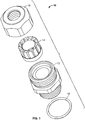
- a liquid-tight connector 10 includes a generally cylindrical body 12, a finger/gland assembly 14 , a compression nut 16 , and a sealing element 18 .
- the sealing element 18 is an O-ring 18 .
- the body 12 and the compression nut 16 are made from metal, such as stainless steel, while the finger/gland assembly 14 is a collet-type component made from a thermoplastic polymer, thermoset polymer, and/or thermoplastic elastomer.
- the body 12 and compression nut 16 are made from a thermoplastic or thermoset material, which may be filled or non-filled.
- the body 12 includes a first end 20 , a second end 22 opposite the first end 20 , a first threaded portion 24 having a plurality of external threads 26 , and a second threaded portion 28 opposite the first threaded portion 24 and having a plurality of external threads 30 .
- An annular pocket 32 is formed within the first threaded portion 24 at the first end 20 . As will be discussed below, the pocket 32 is adapted to receive the finger/gland assembly 14 .
- a centrally located passage 34 extends from the first end 20 to the second end 22 of the body 12 . In an embodiment, the passage 34 is sized and shaped to receive a cable, wire, tube, or other suitable elongated member.
- the first and second threaded portions 24 , 28 are separated from one another by an outwardly-extending external shoulder 36 .
- the shoulder 36 includes a first side 38 and a second side 40 opposite the first side 38 .
- the second side 40 of the shoulder 36 includes a circumferentially extending groove 42 that is adapted to receive the O-ring 18 .
- the second side 40 does not include the groove 42 .
- the shoulder 36 is hexagonal in shape and adapted to receive an installation tool, such as a wrench. In other embodiments, the shoulder 36 consists of other suitable shapes and sizes.
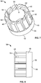
- the finger/gland assembly 14 includes a sealing gland 46 and a plurality of fingers 48 attached to the sealing gland 46 in an annular, collet-type fashion, which will be described in greater detail below.
- the plurality of fingers 48 are inserted into the gland 46 .
- the plurality of fingers 48 are securely held by the gland 46 .
- the sealing gland 46 and the plurality of fingers 48 are integral with one another.
- the sealing gland 46 and the plurality of fingers 48 are co-molded with one another.
- the fingers 48 include a thermoplastic material.
- the sealing gland 46 includes an elastomer or a thermoplastic elastomer.
- the sealing gland 46 includes a first end 50 , a second end 52 opposite the first end 50 , a bevel 54 formed at the first end 50 , and a base portion 56 formed at the second end 52 .
- An opening 55 extends from the first end 50 to the second end 52 .
- the sealing gland 46 includes an outer circumferential wall 58 and an annular flange 60 (also referred to herein as a collar 60 ) that surrounds the outer circumferential wall 58 and extends from the base portion 56 toward the first end 50 of the gland 46 .
- Each of the fingers 48 is an elongated element including a first end 62 having a triangular-shape surface 64 , a second end 66 opposite the first end 62 and having a lower notched portion 68 that is adapted to engage the collar 60 and the base portion 56 , and an inner wall 70 facing the sealing gland 46 .
- Each of the fingers 48 includes an upper notched portion 72 formed proximate to the first end 62 thereof and within the inner wall 70 .
- the finger/gland assembly 14 may be co-molded, such that that the second ends 66 of the fingers 48 engage the outer circumferential wall 58 , the collar 60 , and the base 56 of the finger/gland assembly 14 such that the second ends 66 of the fingers 48 are restrained thereby, and the outer circumferential wall 58 of the sealing gland 46 is juxtaposed with and engages the inner walls 70 of the fingers 48 .
- the first ends 62 of the fingers 48 extend over the first end 50 of the sealing gland 46 , such that the upper notched portions 72 of the fingers 48 engage the bevel 54 and cradle the gland 46 .
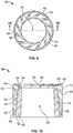
- the compression nut 16 includes a first end 74 , a second end 76 opposite the first end 74 , a nut body 78 and a dome 80 extending from the nut body 78 to the second end 76 .
- the compression nut 18 includes an opening 82 extending from the first end 74 to the second end 76 and defining an interior portion 84 . Extending within the interior portion 84 from the dome 80 is a conically-shaped internal surface 86 .
- the nut body 78 includes internal threads 88 .
- the internal threads 88 are adapted to engage threadedly the external threads 26 of the first threaded portion 24 of the body 12 .
- the compression nut 16 is hexagonal in shape. In other embodiments, the compression nut 16 consists of other shapes and sizes.
- the liquid-tight connector 10 is adapted to be affixed in a liquid-tight manner in an aperture of a workpiece (not shown in the Figures), in which a cable 100 (or other suitable elongated member, such as a wire, cable, tube or rod) passes through it and be locked in liquid-tight engagement, as shown in FIG. 15 .
- the cable 100 may first be installed through the connector 10 , after which the connector 10 may be engaged in position along the cable 100 and then affixed in an aperture and have the cable 100 engaged tightly.
- the conical internal surface 86 of the dome 80 of the compression nut 16 engages the fingers 48 of the finger/gland assembly 14 in a bearing relationship and biases them towards the center of the central passage 34 of the body 12 .
- the inner walls 70 of the fingers 48 compress the outer circumferential wall 58 of the sealing gland 46 and the sealing gland 46 collapses inwardly and engages the cable 100 in liquid-tight engagement around its entire circumference.
- the triangular-shaped surfaces 64 of the fingers 48 further grasp the cable 100 , serving as a strain relief holding of the cable 100 , and providing an additional seal against liquid penetration.
- the engagement of the sealing gland 46 and fingers 48 of the finger/gland assembly 16 against the cable 100 provide a tight, circumferential grasping fit, strain relief, and a liquid-tight seal.
- the fingers 48 can reduce to a very small diameter and engage a number of diameter sizes.
- the ratcheting of the compression nut 16 provides for anti-vibration protection and ensures a firm grip on the cable 100 .
- the use of an integral finger/gland assembly or a co-molded finger/gland assembly allows the finger/gland assembly to provide a tight, circumferential grasping fit, strain relief, and liquid-tight seal around smaller-diameter workpieces than are provided by connectors known in the prior art.
- the O-ring 18 is arranged in the O-ring groove 42 such that the O-ring 18 may form a liquid-tight seal between the second surface 40 of the shoulder 36 and a surface of a workpiece (not shown in the Figures), such as an cabinet or other furnishing, with the second threaded portion 28 of the body 12 inserted through an aperture in the workpiece.
- the body 12 is provided without the groove 42 , but includes an O-ring 18 arranged such that the O-ring 18 may be compressed between the second surface 40 of the shoulder 36 and the surface of the workpiece to form the liquid-tight seal.
- a liquid-tight seal is provided by a sealing element other than an O-ring 18 that is capable of forming a liquid-tight seal between the second surface 40 of the shoulder 36 and a surface of a workpiece.
- a sealing element may be a gasket of a type described in more detail hereinbelow.
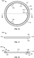
- FIGS. 16-18 illustrate a sealing element 110 in the exemplary form of a gasket 110 suitable for employment in a second embodiment of a liquid-tight connector according to a second embodiment of the present invention.
- the gasket 110 may be made of one or more of a soft elastomeric material, a thermoplastic elastomer, a soft metal, or other deformable material.
- the gasket 110 includes a gasket body 112 having an annular shape, a substantially flat upper surface 114 , a substantially flat lower surface 116 , an annular outer surface 118 extending from the upper surface 114 to the lower surface 116 , and an annular inner surface 120 opposite the outer surface 118 and extending from the upper surface 114 to the lower surface 116 .
- the upper surface 114 has a first outer annular ridge 122 near the outer surface 118 and extending away from the upper surface 114 , and a first inner annular ridge 124 near the inner surface 120 and extending away from the upper surface 114 .
- the lower surface 116 has a second outer annular ridge 126 near the outer surface 118 and extending away from the lower surface 116 , and a second inner annular ridge 128 near the inner surface 120 and extending away from the lower surface 116 .
- the gasket 110 is provided with a plurality of retaining tabs 130 that are integral with the inner surface 120 and extend away therefrom. The retaining tabs 130 are suitable for engaging with a threaded structure (not shown in FIGS. 16-18 ) such that the gasket 110 is retained on the threaded structure.
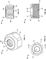
- the fluid-tight connector 210 illustrated therein has numerous components and features that are the same or substantially the same as the components of the fluid-tight connector 10 that are discussed above in relation to FIGS. 1-15 . Reference numbers for such components and features have been incremented by 200 when shown in FIGS. 19-20 relative to the reference numbers for the corresponding components and features shown in FIGS. 1-15 . Such components and features shown in FIGS. 19-20 should be considered to be the same as described with respect to FIGS. 1-15 , unless indicated otherwise hereinbelow. Further, the fluid-tight connector 210 should be considered to operate in the same manner as the fluid tight connector 10 , unless indicated otherwise hereinbelow.
- the second side 40 of the shoulder 36 of connector 10 shown in FIGS. 1-2 is provided with a groove 42 for an O-ring 18 .
- no groove is provided at the second side 240 of the shoulder 236 of connector 210 .
- the gasket 110 is provided as a sealing element at the second side 240 of the shoulder 236 (see FIGS. 19-20 ). Referring to FIG.
- the gasket 110 is placed on the second threaded portion 228 of the body 212 with its first outer annular ridge 122 and first inner annular ridge 124 in contact with the second side 240 of the shoulder 236 and its retaining tabs 130 engaging one or more of the plurality of external threads 230 such that the gasket 110 is retained on the second threaded portion 228 .
- the gasket 110 may form a liquid-tight seal between the second surface 240 of the shoulder 236 and a surface of a workpiece (not shown in the Figures), such as an cabinet or other furnishing, with the second threaded portion 228 of the body 212 inserted through an aperture in the workpiece.
- a workpiece not shown in the Figures
- Such an arrangement can also create and maintain a liquid-tight seal between surfaces that are not completely smooth, which might not be readily created or maintained using an O-ring of connector 10 .
- a gasket may be employed that has more or fewer annular ridges than the gasket 110 , but otherwise has the same features as gasket 110 .
- the gasket may have no annular ridges.
- a gasket may be employed that has more or fewer retaining tabs than the gasket 110 .
- the gasket may have no retaining tabs.
- the gasket may be an annular gasket of any type known in the art that is capable of forming a seal between two surfaces when compressed between the two surfaces.
Landscapes
- Engineering & Computer Science (AREA)
- General Engineering & Computer Science (AREA)
- Mechanical Engineering (AREA)
- Architecture (AREA)
- Civil Engineering (AREA)
- Structural Engineering (AREA)
- Gasket Seals (AREA)
Claims (13)
- Assemblage du type à mandrin, comprenant :- un gland d'étanchéité (46, 246) ayant une paire d'extrémités (50, 52, 250, 252) opposées l'une à l'autre, une ouverture interne (55) s'étendant depuis l'une de ladite paire d'extrémités (50, 52, 250, 252) jusqu'à l'autre de ladite paire d'extrémités (50, 52, 250, 252), un biseau (54, 254) formé au niveau de ladite une extrémité (50, 250) dudit gland d'étanchéité (46, 246), une portion de base (56) formée au niveau de ladite autre extrémité (52, 252) dudit gland d'étanchéité (46), une paroi circonférentielle extérieure (58, 258) s'étendant depuis ladite portion de base (56) jusqu'à ladite une extrémité (50, 250) dudit gland d'étanchéité (46, 246), et une bride annulaire (60, 260) entourant ladite paroi circonférentielle extérieure (58, 258) et s'étendant depuis ladite portion de base (56) vers ladite une extrémité (50, 250) dudit gland d'étanchéité (46, 246) ; et- une pluralité de doigts allongés élastiques (48, 248), chaque doigt (48, 248) ayant une première extrémité (62, 262) et une seconde extrémité (66, 266) opposée à ladite première extrémité (62, 262), ladite pluralité de doigts (48, 248) s'étendant depuis ladite bride annulaire (60, 260) vers ladite une extrémité (50, 250) dudit gland d'étanchéité (46, 246) avec lesdites secondes extrémités (66, 266) desdits doigts (48, 248) à proximité de ladite portion de base (56), chacune desdites secondes extrémités (66, 266) desdits doigts (48, 248) ayant une portion à encoche (68, 268) en assise contre ladite bride annulaire (60, 260) dudit gland d'étanchéité (46, 246), lesdites secondes extrémités (66, 266) desdits doigts (48, 248) engageant ladite paroi circonférentielle extérieure (58, 258), ladite bride annulaire (60, 260) et ladite portion de base (56) dudit gland d'étanchéité (46, 246) et étant retenues entre ladite portion de base (56), ladite bride annulaire (60, 260) et ladite paroi circonférentielle extérieure (58, 258) dudit gland d'étanchéité (46, 246).
- Assemblage du type à mandrin selon la revendication 1,
dans lequel ledit gland d'étanchéité (46, 246) et lesdites secondes extrémités (66, 266) desdits doigts (48, 248) sont formés intégralement l'un avec les autres ; ou
dans lequel ledit gland d'étanchéité (46, 246) et lesdites secondes extrémités (66, 266) desdits doigts (48, 248) sont co-moulés l'un avec les autres ; ou
dans lequel ledit gland d'étanchéité (46, 246) inclut un premier matériau et lesdits doigts (48, 248) incluent un second matériau, ledit premier matériau ayant une élasticité supérieure à celle du second matériau. - Assemblage du type à mandrin selon la revendication 1 ou 2,
dans lequel chaque doigt (48, 248) de ladite pluralité de doigts (48, 248) inclut une paroi intérieure (70, 270) faisant face audit gland d'étanchéité (46, 246), qui est juxtaposée à et s'engage avec ladite paroi circonférentielle extérieure (58, 258) dudit gland d'étanchéité (46, 246). - Assemblage du type à mandrin selon la revendication 3,
dans lequel lesdites premières extrémités (62, 262) desdits doigts (48, 248) ont des portions à encoche supérieures (72, 272) formées à proximité desdites premières extrémités (62, 262) desdits doigts (48, 248) et à l'intérieur desdites parois intérieures (70, 270) de celles-ci, lesdites premières extrémités (62, 262) desdits doigts (48, 248) s'étendant au-delà de ladite une extrémité (50, 250) dudit gland d'étanchéité (46, 246) de sorte que lesdites portions à encoche supérieures (72, 272) desdits doigts (48, 248) engagent ledit biseau (54, 254) dudit gland d'étanchéité (46, 246) et nichent ledit gland d'étanchéité (46, 246),
dans lequel lesdits doigts (48, 248) ont de préférence des surfaces de forme triangulaire (64, 264) au niveau de leurs premières extrémités (62, 262). - Connecteur étanche aux liquides (10, 210), comprenant :- l'assemblage du type à mandrin selon la revendication 1 ;- un corps cylindrique (12, 212) ayant une première extrémité (20, 220) dudit corps (12, 212) et une seconde extrémité (22, 222) dudit corps (12, 212) opposée à ladite première extrémité (20, 220) dudit corps (12, 212), un épaulement annulaire externe s'étendant vers l'extérieur (36, 236) situé au niveau d'une position entre ladite première extrémité (20, 220) et ladite seconde extrémité (22, 222) dudit corps (12, 212) et ayant une première surface (38, 238) faisant face à ladite première extrémité (20, 220) dudit corps (12, 212) et une seconde surface (40, 240) opposée à ladite première surface (38, 238), une première portion à pas de vis (24, 224) ayant une première pluralité de pas de vis externes (26, 226) s'étendant depuis ladite première extrémité (20, 220) dudit corps (12, 212) vers ledit épaulement (36, 236), une poche annulaire (32) à l'intérieur de ladite première portion à pas de vis (24, 224) et au niveau de ladite première extrémité (20, 220) dudit corps (12, 212), et un passage centralement situé (34, 234) dudit corps (12, 212) s'étendant depuis ladite première extrémité (20, 220) dudit corps (12, 212) jusqu'à ladite seconde extrémité (22, 222) dudit corps (12, 212) et s'ouvrant sur ladite poche annulaire (32), ledit passage centralement situé (34, 234) dudit corps (12, 212) étant adapté pour recevoir la pièce à œuvrer allongée à l'intérieur de celui-ci, ladite poche annulaire (32) étant adaptée pour recevoir ledit assemblage du type à mandrin et ayant ledit assemblage du type à mandrin à l'intérieur d'elle-même avec ladite ouverture interne (55) dudit gland d'étanchéité (46, 246) sensiblement alignée avec ledit passage centralement situé (34, 234) dudit corps (12, 212) ; et- un écrou de compression (16, 216), incluant une première extrémité (74, 274) dudit écrou de compression (16, 216), une seconde extrémité (76, 276) dudit écrou de compression (16, 216) opposée à ladite première extrémité (74, 274) dudit écrou de compression (16, 216), un corps d'écrou (78, 278), une dôme (80, 280) s'étendant depuis ledit corps d'écrou (78, 278) jusqu'à la seconde extrémité (76, 276) dudit écrou de compression (16, 216), une ouverture (82, 282) s'étendant depuis ladite première extrémité (74, 274) dudit écrou de compression (16, 216) jusqu'à ladite seconde extrémité (76, 276) dudit écrou de compression (16, 216) et définissant une portion intérieure (84, 284) dudit écrou de compression (16, 216), ladite portion intérieure (84, 284) ayant une surface interne de forme conique (86, 286) s'étendant depuis ledit dôme (80, 280) et s'élargissant vers ladite seconde extrémité (76, 276) dudit écrou de compression (16, 216), et une pluralité de pas de vis internes (88, 288) s'étendant depuis ladite seconde extrémité (76, 276) vers ladite surface interne de forme conique (86, 286), ladite pluralité de pas de vis internes (88, 288) étant agencés pour s'engager par vissage avec ladite première pluralité de pas de vis externes (26, 226) de ladite première portion à pas de vis (24, 224) dudit corps (12, 212).
- Connecteur étanche aux liquides (10, 210) selon la revendication 5, dans lequel, quand ladite pièce à œuvrer est reçue à l'intérieur de ladite ouverture interne (55) dudit gland d'étanchéité (46, 246) et dudit passage centralement situé (34, 234) dudit corps (12, 212), ledit écrou de compression (16, 216) s'engage par vissage avec ladite première portion à pas de vis (24, 224) dudit corps (12, 212), ladite surface interne conique (86, 286) dudit dôme (80, 280) s'engage avec lesdits doigts (48, 248) dans une relation en appui et sollicite lesdites premières extrémités (62, 262) desdits doigts (48, 248) les unes vers les autres de sorte que lesdits doigts (48, 248) compriment ladite paroi circonférentielle extérieure (58, 258) dudit gland d'étanchéité (46, 246) de sorte que ledit gland d'étanchéité (46, 246) s'effondre vers l'intérieur, engageant ainsi la pièce à œuvrer dans un engagement étanche aux liquides autour de sa circonférence entière.
- Connecteur étanche aux liquides (10, 210) selon la revendication 5 ou 6, dans lequel ledit gland d'étanchéité (46, 246) et lesdites secondes extrémités (66, 266) desdits doigts (48, 248) sont formés intégralement l'un avec les autres ; ou
dans lequel ledit gland d'étanchéité (46, 246) et lesdites secondes extrémités (66, 266) desdits doigts (48, 248) sont co-moulés l'un avec les autres ; ou
dans lequel ledit gland d'étanchéité (46, 246) inclut un premier matériau et lesdits doigts (48, 248) incluent un second matériau, ledit premier matériau ayant une élasticité supérieure à celle dudit second matériau. - Connecteur étanche aux liquides (10, 210) selon la revendication 7,
dans lequel chaque doigt (48, 248) de ladite pluralité de doigts (48, 248) inclut une paroi intérieure (70, 270) faisant face audit gland d'étanchéité (46, 246), qui est juxtaposée à et s'engage avec ladite paroi circonférentielle extérieure (58, 258) dudit gland d'étanchéité (46, 246). - Connecteur étanche aux liquides (10, 210) selon la revendication 8,
dans lequel lesdites premières extrémités (62, 262) desdits doigts (48, 248) ont des portions à encoche supérieures (72, 272) formées à proximité desdites premières extrémités (62, 262) desdits doigts (48, 248) et à l'intérieur desdites parois intérieures (70, 270) de celles-ci, lesdites premières extrémités (62, 262) desdits doigts (48, 248) s'étendant au-delà de ladite une extrémité (50, 250) dudit gland d'étanchéité (46, 246) de sorte que lesdites portions à encoche supérieures (72, 272) desdits doigts (48, 248) engagent ledit biseau (54, 254) dudit gland d'étanchéité (46, 246) et nichent ledit gland d'étanchéité (46, 246). - Connecteur étanche aux liquides (10, 210) selon la revendication 9,
dans lequel lesdits doigts (48, 248) ont des surfaces de forme triangulaire (64, 264) au niveau de leurs premières extrémités (62, 262). - Connecteur étanche aux liquides (10, 210) selon l'une des revendications 5 ou 6,
dans lequel lesdits doigts (48, 248) saisissent la pièce à œuvrer, assurant ainsi un maintien de décharge de traction de la pièce à œuvrer. - Connecteur étanche aux liquides (10) selon la revendication 5,
incluant en outre une gorge annulaire (42) destinée à recevoir un élément d'étanchéité annulaire (18), ladite gorge annulaire (42) étant située dans ladite seconde extrémité (40) dudit épaulement (36) autour dudit passage centralement situé (34). - Connecteur étanche aux liquides (10, 210) selon la revendication 5, comprenant en outre une seconde portion à pas de vis (28, 228) ayant une seconde pluralité de pas de vis externes (30, 230) s'étendant depuis ladite seconde extrémité (22, 222) dudit corps (12, 212) vers ledit épaulement (36, 236), et un élément d'étanchéité annulaire (110) autour dudit passage centralement situé (234) et engagé avec ladite seconde pluralité de pas de vis externes (230).
Priority Applications (1)
| Application Number | Priority Date | Filing Date | Title |
|---|---|---|---|
| PL14755534T PL3033559T3 (pl) | 2013-08-14 | 2014-08-14 | Zespół typu kołnierzowego i nieprzepuszczające cieczy złącze z takim zespołem |
Applications Claiming Priority (2)
| Application Number | Priority Date | Filing Date | Title |
|---|---|---|---|
| US201361865832P | 2013-08-14 | 2013-08-14 | |
| PCT/US2014/051004 WO2015023814A1 (fr) | 2013-08-14 | 2014-08-14 | Raccord étanche aux liquides |
Publications (2)
| Publication Number | Publication Date |
|---|---|
| EP3033559A1 EP3033559A1 (fr) | 2016-06-22 |
| EP3033559B1 true EP3033559B1 (fr) | 2021-06-02 |
Family
ID=51398939
Family Applications (1)
| Application Number | Title | Priority Date | Filing Date |
|---|---|---|---|
| EP14755534.6A Active EP3033559B1 (fr) | 2013-08-14 | 2014-08-14 | Assemblage à mandrin et raccord étanche aux liquides avec un tel assemblage |
Country Status (5)
| Country | Link |
|---|---|
| US (1) | US9371948B2 (fr) |
| EP (1) | EP3033559B1 (fr) |
| ES (1) | ES2879945T3 (fr) |
| PL (1) | PL3033559T3 (fr) |
| WO (1) | WO2015023814A1 (fr) |
Families Citing this family (17)
| Publication number | Priority date | Publication date | Assignee | Title |
|---|---|---|---|---|
| MY153846A (en) * | 2009-08-21 | 2015-03-31 | Cmp Products Ltd | Filler assembly for cable gland |
| USD787648S1 (en) * | 2013-10-31 | 2017-05-23 | Bridgeport Fittings, Inc. | Raintight fitting connector body |
| US9601914B2 (en) * | 2014-01-13 | 2017-03-21 | Avc Industrial Corp. | Cable and flexible conduit gland assembly |
| GB2542775B (en) * | 2015-09-25 | 2022-01-19 | Hubbell Ltd | Cable gland assembly |
| DE102016113655A1 (de) * | 2016-07-25 | 2018-01-25 | Pflitsch Gmbh & Co. Kg | Vorrichtung zur abgedichteten Durchführung eines Langformteils |
| US10981189B2 (en) | 2017-07-07 | 2021-04-20 | Anvil International, Llc | Hanging connector for flexible sprinkler conduit |
| USD919059S1 (en) * | 2017-07-18 | 2021-05-11 | Louis Ray | Plumbing fitting |
| USD910420S1 (en) * | 2017-08-25 | 2021-02-16 | Gem Products, Inc. | Attachment point for an outrigger guide |
| USD854915S1 (en) * | 2017-11-08 | 2019-07-30 | Anvil International, Llc | Conduit hanger adapter |
| US10801645B2 (en) * | 2017-12-28 | 2020-10-13 | Nexans | Dynamic application cable assembly with adjustable armor clamp |
| USD838676S1 (en) * | 2017-12-29 | 2019-01-22 | Bridgeport Fittings, Inc. | Slip electrical conduit coupler body |
| CN109081298B (zh) * | 2018-08-07 | 2020-05-19 | 塔罗斯科技股份有限公司 | 一种酒塔与灯牌的连接结构 |
| US11050321B2 (en) * | 2018-09-18 | 2021-06-29 | Nidec Motor Corporation | Motor conduit plug |
| USD913332S1 (en) | 2018-11-02 | 2021-03-16 | Nidec Motor Corporation | Motor conduit plug |
| US11788625B2 (en) | 2020-05-27 | 2023-10-17 | Hoffman Enclosures, Inc. | Hygienic hole seal |
| CN113013799B (zh) * | 2021-02-26 | 2023-02-03 | 立讯精密工业股份有限公司 | 一种线缆固定夹具及数据传输装置 |
| PL440336A1 (pl) * | 2022-02-09 | 2023-08-14 | Produced In Internet Spółka Z Ograniczoną Odpowiedzialnością | Sposób i dławica do mocowania przewodu, zwłaszcza elektrycznego |
Family Cites Families (98)
| Publication number | Priority date | Publication date | Assignee | Title |
|---|---|---|---|---|
| US682847A (en) | 1900-07-27 | 1901-09-17 | Curtain Supply Co | Cable-clamp. |
| US1904617A (en) * | 1932-03-18 | 1933-04-18 | Stephen N Buchanan | Cable connecter |
| US2310622A (en) | 1940-09-25 | 1943-02-09 | Adel Prec Products Corp | Conduit fastener |
| US2475322A (en) | 1946-05-10 | 1949-07-05 | Richard J Horton | Coupling device for flexible conduits |
| US2528533A (en) | 1948-12-22 | 1950-11-07 | Frederick L Mcculloch | Juicing machine |
| US2664458A (en) | 1952-01-11 | 1953-12-29 | Illinois Tool Works | Strain-relief grommet |
| US2974186A (en) | 1958-10-03 | 1961-03-07 | Heyman Mfg Company Inc | Strain relief bushing |
| US2967722A (en) | 1959-05-18 | 1961-01-10 | Lifka Charles | Angular connector fittings for flexible conduit |
| US3144695A (en) | 1961-04-24 | 1964-08-18 | Gilbert G Budwig | Mounting device |
| US3262721A (en) | 1964-05-01 | 1966-07-26 | Nelson Mfg Co Inc L R | Snap action hose fitting |
| US3290430A (en) | 1966-01-28 | 1966-12-06 | Heyman Mfg Co | Angle strap strain relief bushings |
| US3376004A (en) | 1966-06-16 | 1968-04-02 | Mc Donnell Douglas Corp | Snap clamp |
| US3464659A (en) | 1967-11-30 | 1969-09-02 | Heyman Mfg Co | Strain relief bushing |
| US3719971A (en) | 1971-03-04 | 1973-03-13 | Richco Plastics Co | Cable hanger and clamp |
| AT309932B (de) * | 1971-07-28 | 1973-09-10 | Hummel Metallwarenfab A | Verschraubung zum Anschließen von Rohrleitungen und zum Einführen elektrischer Kabel |
| US3809798A (en) | 1972-09-06 | 1974-05-07 | H Simon | Angle type feedthrough cable clamp |
| US4034944A (en) | 1973-05-18 | 1977-07-12 | Eaton Corporation | Strain-relief bushing |
| GB1442169A (en) | 1973-10-15 | 1976-07-07 | Plastic Seals Ltd | Bushing or grommet devices |
| US4000875A (en) | 1974-06-11 | 1977-01-04 | Heyman Manufacturing Company | One-piece strain relief bushing with independent holding means |
| US3972547A (en) | 1974-11-21 | 1976-08-03 | Zenzo Ono | Locking and nonseal joint device |
| US3958300A (en) | 1975-10-10 | 1976-05-25 | Nifco Inc. | Plastic device for clamping and holding a length of electric cord |
| GB1543678A (en) * | 1976-07-16 | 1979-04-04 | Lapp Kg U | Clamping device for cables leads hoses or the like |
| US4194768A (en) | 1977-12-30 | 1980-03-25 | The Scott & Fetzer Company | Liquid-tight connector |
| JPS5744731Y2 (fr) * | 1978-01-26 | 1982-10-02 | ||
| US4225162A (en) | 1978-09-20 | 1980-09-30 | Amp Incorporated | Liquid tight connector |
| US4224464A (en) | 1978-10-24 | 1980-09-23 | Amp Incorporated | Liquid tight connector |
| US4302035A (en) | 1979-03-12 | 1981-11-24 | Ochwat Richard S | One piece electrical connector |
| US4264047A (en) | 1979-10-29 | 1981-04-28 | Illinois Tool Works Inc. | Brake and fuel line clip |
| US4323727A (en) | 1980-10-21 | 1982-04-06 | Crouse-Hinds Company | Cable strain relief and sealing apparatus |
| US4400022A (en) | 1980-12-22 | 1983-08-23 | Simmonds Precision Products, Inc. | Tube connector |
| EP0058739B1 (fr) | 1981-02-13 | 1985-02-20 | Hans Simon | Traversée de câble à soulagement de traction |
| DE3108085C2 (de) | 1981-03-04 | 1984-05-03 | Karl 7298 Loßburg Hehl | Winkelzugentlastungsvorrichtung zur Einführung elektrischer Versorgungsleitungen in ein Gerät |
| DE3126488C2 (de) | 1981-07-04 | 1983-04-21 | Fa. A. Raymond, 7850 Lörrach | Rohrschelle |
| US4490576A (en) | 1981-08-10 | 1984-12-25 | Appleton Electric Co. | Connector for use with jacketed metal clad cable |
| US4457544A (en) | 1981-08-13 | 1984-07-03 | Liquid Tight Corporation | Connector for flexible electrical conduit |
| FR2528533B1 (fr) | 1982-06-09 | 1986-04-11 | Capri Codec Sa | Raccord traversant a ecrou tournant pour gaine exterieurement spiralee |
| US4494779A (en) | 1982-07-14 | 1985-01-22 | Thyssen-Bornemisza Inc. | Connector fitting for electrical box |
| JPS59122305A (ja) * | 1982-12-25 | 1984-07-14 | 日幸工業株式会社 | ケ−ブル類の固定具 |
| JPS6052683U (ja) | 1983-09-16 | 1985-04-13 | 北川工業株式会社 | コ−ドブツシング |
| DE3403774A1 (de) | 1984-02-03 | 1985-08-08 | Anton Hummel Gmbh Metallwarenfabrik, 7808 Waldkirch | Winkelfoermige leitungseinfuehrung |
| DE3403772C2 (de) | 1984-02-03 | 1987-04-02 | Anton Hummel Gmbh Metallwarenfabrik, 7808 Waldkirch | Winkelförmige Leitungseinführung |
| JPH0229629Y2 (fr) | 1985-03-11 | 1990-08-09 | ||
| US5304742A (en) | 1985-08-12 | 1994-04-19 | Leviton Manufacturing Co., Inc. | Strain relief device |
| US4692562A (en) | 1985-09-26 | 1987-09-08 | Commander Electrical Materials, Inc. | Seal for a cable connector |
| US4708370A (en) | 1985-11-14 | 1987-11-24 | Toddco | Recreational vehicle discharge pipe coupler |
| US4698459A (en) | 1986-10-08 | 1987-10-06 | Dorman Products, Inc. | Battery connection protector case |
| US4729534A (en) | 1986-10-23 | 1988-03-08 | Micro Plastics, Inc. | Strain relief bushings |
| US4739126A (en) | 1987-01-16 | 1988-04-19 | Amp Incorporated | Panel mount ground termination apparatus |
| DE3709963C1 (de) | 1987-03-26 | 1988-05-26 | Hummel Metallwarenfab A | Winkelfoermige Leitungseinfuehrung |
| US4775121A (en) | 1987-07-20 | 1988-10-04 | Carty James F | Cable clamp |
| GB2219146B (en) | 1988-04-13 | 1992-10-28 | Cmp | Improvements in cable glands |
| US4835342A (en) | 1988-06-27 | 1989-05-30 | Berger Industries, Inc. | Strain relief liquid tight electrical connector |
| US4874325A (en) | 1988-09-23 | 1989-10-17 | General Motors Corporation | Electrical connector with interface seal |
| US4903995A (en) | 1988-09-30 | 1990-02-27 | Colder Products Company | Self-tightening soft tubing fitting and method of use |
| US4888453A (en) | 1988-10-20 | 1989-12-19 | General Motors Corporation | Panel mounted breakout fitting |
| US4913385A (en) | 1989-05-10 | 1990-04-03 | Heyco Molded Products, Inc. | Self-locking strain relief bushing for variable panel thicknesses and method |
| US5098310A (en) | 1990-02-20 | 1992-03-24 | Woodhead Industries, Inc. | Electrical connector assembly with improved water seal |
| US5388866A (en) | 1990-03-09 | 1995-02-14 | Lourdes Industries | High pressure coupling with provision for preventing separation of parts and with anti-galling provision |
| US5072072A (en) | 1990-03-23 | 1991-12-10 | Thomas & Betts Corporation | Electrical connector for liquidtight conduit |
| DE9011069U1 (de) * | 1990-07-26 | 1990-10-04 | Schaltbau GmbH, 81677 München | Zugentlastung für ein Kabel |
| US5226837A (en) | 1990-11-16 | 1993-07-13 | Raychem Corporation | Environmentally protected connection |
| US5132493A (en) | 1991-01-25 | 1992-07-21 | Sheehan Robert K | Device for connecting non-metallic sheathed cable to an electric box |
| US5200575A (en) | 1991-01-25 | 1993-04-06 | Sheehan Robert K | Connector assembly for conduit |
| US5113717A (en) | 1991-01-30 | 1992-05-19 | Teleflex Incorporated | Motion transmitting remote control assembly with a conduit locator connecting means |
| GB2258350B (en) | 1991-07-20 | 1995-08-02 | Hawke Cable Glands Ltd | Electric cable barrier gland |
| US5318459A (en) | 1992-03-18 | 1994-06-07 | Shields Winston E | Ruggedized, sealed quick disconnect electrical coupler |
| US5346264A (en) | 1992-03-19 | 1994-09-13 | Heyco Molded Products, Inc. | Liquid tight internal snap connector for connecting corrugated plastic conduit |
| DE4225742A1 (de) | 1992-08-04 | 1994-02-10 | United Carr Gmbh Trw | Halteelement |
| US5321205B1 (en) | 1993-01-15 | 1997-02-04 | Thomas & Betts Corp | Electrical connector fitting |
| US5405172A (en) | 1993-05-13 | 1995-04-11 | Heyco Molded Products, Inc. | Plastic liquid tight connector for cable, tubes or rods |
| US5866853A (en) * | 1993-10-07 | 1999-02-02 | Sheehan; Robert K. | Liquid-tight, strain-relief connector for connecting conduit and the like |
| US5390876A (en) | 1993-11-19 | 1995-02-21 | Sumitomo Denso Kabushiki Kaisha | Holder for fixing wiring harness and the like to automobile body |
| JP3340212B2 (ja) | 1993-12-09 | 2002-11-05 | ファナック株式会社 | 電動機用ケーブルクランプ |
| BR9501003A (pt) | 1994-03-09 | 1995-10-17 | Bundy Int Ltd | Mordente bloqueador de tubos particularmente para tubulações de alimentação de motores a combustão |
| US5494245A (en) | 1994-05-04 | 1996-02-27 | Yazaki Corporation | Wiring harness retainer clip |
| US6044868A (en) | 1995-02-24 | 2000-04-04 | Arlington Industries, Inc. | Watertight fitting for flexible non-metallic conduit |
| US6102442A (en) | 1995-02-24 | 2000-08-15 | Arlington Industries, Inc. | Waterlight fitting for flexible conduit |
| US5543582A (en) | 1995-05-23 | 1996-08-06 | Stark; Thomas S. | Liquid tight cord grip |
| DE19544963A1 (de) | 1995-12-04 | 1997-06-05 | Bopla Gehaeuse Systeme Gmbh | Kabelverschraubung |
| US5820048A (en) | 1996-04-09 | 1998-10-13 | Illinois Tool Works Inc. | Side latching hinge mechanism |
| US6102445C1 (en) | 1996-09-11 | 2002-05-21 | Tru Flex Meal Hose Corp | Sealed coupling system for flexible hose |
| JP2001513170A (ja) | 1997-02-13 | 2001-08-28 | ヘイコ プロダクツ インク | 90゜シーリングナット |
| US6300569B1 (en) | 1997-02-13 | 2001-10-09 | Heyco Products, Inc. | 90° sealing nut |
| US5872335A (en) | 1997-06-30 | 1999-02-16 | Heyco Products, Inc. | 90 degree sealing nut |
| US6231085B1 (en) | 1997-04-21 | 2001-05-15 | Irrigation Development Company | Tubing coupling and hose end combination, and related method |
| US6164604A (en) | 1998-02-03 | 2000-12-26 | Oatey Co. | Pipe clamps |
| US5984373A (en) | 1998-03-12 | 1999-11-16 | Elcam Plastic Kibbutz Bar-Am | Luer connector |
| US6142429A (en) | 1999-01-25 | 2000-11-07 | Ahroni; Joseph M. | Mounting clips for a draping decorative light string |
| US6311935B1 (en) | 1999-07-07 | 2001-11-06 | Heyco Products, Inc. | Cable clamp |
| DE19951455C1 (de) * | 1999-10-25 | 2001-10-25 | Phoenix Contact Gmbh & Co | Kabelanschluss- oder -verbindungseinrichtung |
| US6488317B1 (en) * | 2000-02-01 | 2002-12-03 | Avaya Technology Corp. | Cable strain relief adapter with gel sealing grommet |
| US6585297B2 (en) | 2000-09-20 | 2003-07-01 | Heyco, Inc. | Single-piece liquid-tight connector with snap-on cuff |
| DE10312749B4 (de) * | 2003-03-21 | 2005-11-03 | Pflitsch Gmbh & Co. Kg | Verschraubung für abgedichtete Leitungsdurchführungen |
| US20060219437A1 (en) | 2005-03-18 | 2006-10-05 | Teh-Tsung Chiu | Tight-sealed cable connector |
| US7431602B2 (en) * | 2005-04-21 | 2008-10-07 | Dsm & T Co., Inc. | Electrical connector |
| DE202005014138U1 (de) | 2005-09-07 | 2005-11-10 | Anton Hummel Verwaltungs-Gmbh | Bausatz oder Set umfassend wenigstens zwei unterschiedlich bemessene Typen von Kabelverschraubungen |
| US7563993B2 (en) * | 2006-09-22 | 2009-07-21 | Lapp Engineering & Co. | Insert for an opening of an appliance |
| US9601914B2 (en) * | 2014-01-13 | 2017-03-21 | Avc Industrial Corp. | Cable and flexible conduit gland assembly |
-
2014
- 2014-08-14 ES ES14755534T patent/ES2879945T3/es active Active
- 2014-08-14 WO PCT/US2014/051004 patent/WO2015023814A1/fr active Application Filing
- 2014-08-14 US US14/459,495 patent/US9371948B2/en active Active
- 2014-08-14 EP EP14755534.6A patent/EP3033559B1/fr active Active
- 2014-08-14 PL PL14755534T patent/PL3033559T3/pl unknown
Non-Patent Citations (1)
| Title |
|---|
| None * |
Also Published As
| Publication number | Publication date |
|---|---|
| EP3033559A1 (fr) | 2016-06-22 |
| US9371948B2 (en) | 2016-06-21 |
| ES2879945T3 (es) | 2021-11-23 |
| US20150048614A1 (en) | 2015-02-19 |
| PL3033559T3 (pl) | 2022-02-14 |
| WO2015023814A1 (fr) | 2015-02-19 |
Similar Documents
| Publication | Publication Date | Title |
|---|---|---|
| EP3033559B1 (fr) | Assemblage à mandrin et raccord étanche aux liquides avec un tel assemblage | |
| US5405172A (en) | Plastic liquid tight connector for cable, tubes or rods | |
| CN107429843B (zh) | 液密式应变消除件 | |
| EP3258155B1 (fr) | Embout de raccord résistant à la traction | |
| EP1678062B1 (fr) | Appareil de prise a cable autobloquant et tendu par ressort | |
| US6241553B1 (en) | Connector for electrical cords and cables | |
| US10573436B2 (en) | Liquid-tight strain relief | |
| EP3430299B1 (fr) | Dispositif, agencement et procédé de raccord instantané | |
| EP3155693B1 (fr) | Raccord à utiliser avec un câble blindé | |
| CA2840669A1 (fr) | Dispositif de retenue de cable electrique utilisant un mandrin a double cone | |
| US2875777A (en) | Hermetic port valve assembly for tapping fluid conduits | |
| KR20220088789A (ko) | 부싱 및 부싱을 포함한 케이블 글랜드 | |
| EP2924826B1 (fr) | Dispositif de retenue de câble à l'aide d'un mandrin à double coin et double matériau | |
| EP2763254A1 (fr) | Appareil permettant de étouper un élément allongé | |
| CA3086564A1 (fr) | Ensemble de fixation pour pompe de distribution de liquide | |
| JP5892872B2 (ja) | 防爆形ケーブルグランドのケーブルクランプ装置。 | |
| KR20180030958A (ko) | 파이프 연결구 | |
| RU2019122605A (ru) | Фитинг для медицинской трубопроводной системы | |
| JP5851944B2 (ja) | 防爆形ケーブルグランドのケーブルクランプ装置 | |
| KR101709723B1 (ko) | 파이프 연결구 | |
| EP2966332B1 (fr) | Soupape de vidange pour un réservoir de fluide sous pression et ledit réservoir comprenant celui-ci | |
| KR101634506B1 (ko) | 개량형 원터치 배관 연결장치 | |
| EP3217058B1 (fr) | Raccord à vis pour relier un élément d'extrémité fileté et une conduite de gaz ou hydraulique ayant une surface lisse |
Legal Events
| Date | Code | Title | Description |
|---|---|---|---|
| PUAI | Public reference made under article 153(3) epc to a published international application that has entered the european phase |
Free format text: ORIGINAL CODE: 0009012 |
|
| 17P | Request for examination filed |
Effective date: 20160219 |
|
| AK | Designated contracting states |
Kind code of ref document: A1 Designated state(s): AL AT BE BG CH CY CZ DE DK EE ES FI FR GB GR HR HU IE IS IT LI LT LU LV MC MK MT NL NO PL PT RO RS SE SI SK SM TR |
|
| AX | Request for extension of the european patent |
Extension state: BA ME |
|
| RAP1 | Party data changed (applicant data changed or rights of an application transferred) |
Owner name: HEYCO PRODUCTS, INC. |
|
| RAP1 | Party data changed (applicant data changed or rights of an application transferred) |
Owner name: FITTINGS ACQUISITION MERGER CO. |
|
| DAX | Request for extension of the european patent (deleted) | ||
| STAA | Information on the status of an ep patent application or granted ep patent |
Free format text: STATUS: EXAMINATION IS IN PROGRESS |
|
| 17Q | First examination report despatched |
Effective date: 20190314 |
|
| GRAP | Despatch of communication of intention to grant a patent |
Free format text: ORIGINAL CODE: EPIDOSNIGR1 |
|
| STAA | Information on the status of an ep patent application or granted ep patent |
Free format text: STATUS: GRANT OF PATENT IS INTENDED |
|
| INTG | Intention to grant announced |
Effective date: 20201215 |
|
| GRAS | Grant fee paid |
Free format text: ORIGINAL CODE: EPIDOSNIGR3 |
|
| GRAA | (expected) grant |
Free format text: ORIGINAL CODE: 0009210 |
|
| STAA | Information on the status of an ep patent application or granted ep patent |
Free format text: STATUS: THE PATENT HAS BEEN GRANTED |
|
| RAP3 | Party data changed (applicant data changed or rights of an application transferred) |
Owner name: HEYCO PRODUCTS CORP. |
|
| REG | Reference to a national code |
Ref country code: CH Ref legal event code: EP |
|
| AK | Designated contracting states |
Kind code of ref document: B1 Designated state(s): AL AT BE BG CH CY CZ DE DK EE ES FI FR GB GR HR HU IE IS IT LI LT LU LV MC MK MT NL NO PL PT RO RS SE SI SK SM TR |
|
| REG | Reference to a national code |
Ref country code: GB Ref legal event code: FG4D |
|
| REG | Reference to a national code |
Ref country code: AT Ref legal event code: REF Ref document number: 1398765 Country of ref document: AT Kind code of ref document: T Effective date: 20210615 |
|
| REG | Reference to a national code |
Ref country code: IE Ref legal event code: FG4D |
|
| REG | Reference to a national code |
Ref country code: DE Ref legal event code: R096 Ref document number: 602014077887 Country of ref document: DE |
|
| REG | Reference to a national code |
Ref country code: LT Ref legal event code: MG9D |
|
| PG25 | Lapsed in a contracting state [announced via postgrant information from national office to epo] |
Ref country code: LT Free format text: LAPSE BECAUSE OF FAILURE TO SUBMIT A TRANSLATION OF THE DESCRIPTION OR TO PAY THE FEE WITHIN THE PRESCRIBED TIME-LIMIT Effective date: 20210602 Ref country code: FI Free format text: LAPSE BECAUSE OF FAILURE TO SUBMIT A TRANSLATION OF THE DESCRIPTION OR TO PAY THE FEE WITHIN THE PRESCRIBED TIME-LIMIT Effective date: 20210602 Ref country code: BG Free format text: LAPSE BECAUSE OF FAILURE TO SUBMIT A TRANSLATION OF THE DESCRIPTION OR TO PAY THE FEE WITHIN THE PRESCRIBED TIME-LIMIT Effective date: 20210902 Ref country code: HR Free format text: LAPSE BECAUSE OF FAILURE TO SUBMIT A TRANSLATION OF THE DESCRIPTION OR TO PAY THE FEE WITHIN THE PRESCRIBED TIME-LIMIT Effective date: 20210602 |
|
| REG | Reference to a national code |
Ref country code: NL Ref legal event code: MP Effective date: 20210602 |
|
| REG | Reference to a national code |
Ref country code: AT Ref legal event code: MK05 Ref document number: 1398765 Country of ref document: AT Kind code of ref document: T Effective date: 20210602 |
|
| REG | Reference to a national code |
Ref country code: ES Ref legal event code: FG2A Ref document number: 2879945 Country of ref document: ES Kind code of ref document: T3 Effective date: 20211123 |
|
| PG25 | Lapsed in a contracting state [announced via postgrant information from national office to epo] |
Ref country code: LV Free format text: LAPSE BECAUSE OF FAILURE TO SUBMIT A TRANSLATION OF THE DESCRIPTION OR TO PAY THE FEE WITHIN THE PRESCRIBED TIME-LIMIT Effective date: 20210602 Ref country code: GR Free format text: LAPSE BECAUSE OF FAILURE TO SUBMIT A TRANSLATION OF THE DESCRIPTION OR TO PAY THE FEE WITHIN THE PRESCRIBED TIME-LIMIT Effective date: 20210903 Ref country code: NO Free format text: LAPSE BECAUSE OF FAILURE TO SUBMIT A TRANSLATION OF THE DESCRIPTION OR TO PAY THE FEE WITHIN THE PRESCRIBED TIME-LIMIT Effective date: 20210902 Ref country code: SE Free format text: LAPSE BECAUSE OF FAILURE TO SUBMIT A TRANSLATION OF THE DESCRIPTION OR TO PAY THE FEE WITHIN THE PRESCRIBED TIME-LIMIT Effective date: 20210602 Ref country code: RS Free format text: LAPSE BECAUSE OF FAILURE TO SUBMIT A TRANSLATION OF THE DESCRIPTION OR TO PAY THE FEE WITHIN THE PRESCRIBED TIME-LIMIT Effective date: 20210602 |
|
| PG25 | Lapsed in a contracting state [announced via postgrant information from national office to epo] |
Ref country code: PT Free format text: LAPSE BECAUSE OF FAILURE TO SUBMIT A TRANSLATION OF THE DESCRIPTION OR TO PAY THE FEE WITHIN THE PRESCRIBED TIME-LIMIT Effective date: 20211004 Ref country code: RO Free format text: LAPSE BECAUSE OF FAILURE TO SUBMIT A TRANSLATION OF THE DESCRIPTION OR TO PAY THE FEE WITHIN THE PRESCRIBED TIME-LIMIT Effective date: 20210602 Ref country code: NL Free format text: LAPSE BECAUSE OF FAILURE TO SUBMIT A TRANSLATION OF THE DESCRIPTION OR TO PAY THE FEE WITHIN THE PRESCRIBED TIME-LIMIT Effective date: 20210602 Ref country code: AT Free format text: LAPSE BECAUSE OF FAILURE TO SUBMIT A TRANSLATION OF THE DESCRIPTION OR TO PAY THE FEE WITHIN THE PRESCRIBED TIME-LIMIT Effective date: 20210602 Ref country code: SM Free format text: LAPSE BECAUSE OF FAILURE TO SUBMIT A TRANSLATION OF THE DESCRIPTION OR TO PAY THE FEE WITHIN THE PRESCRIBED TIME-LIMIT Effective date: 20210602 Ref country code: SK Free format text: LAPSE BECAUSE OF FAILURE TO SUBMIT A TRANSLATION OF THE DESCRIPTION OR TO PAY THE FEE WITHIN THE PRESCRIBED TIME-LIMIT Effective date: 20210602 Ref country code: CZ Free format text: LAPSE BECAUSE OF FAILURE TO SUBMIT A TRANSLATION OF THE DESCRIPTION OR TO PAY THE FEE WITHIN THE PRESCRIBED TIME-LIMIT Effective date: 20210602 Ref country code: EE Free format text: LAPSE BECAUSE OF FAILURE TO SUBMIT A TRANSLATION OF THE DESCRIPTION OR TO PAY THE FEE WITHIN THE PRESCRIBED TIME-LIMIT Effective date: 20210602 |
|
| REG | Reference to a national code |
Ref country code: DE Ref legal event code: R097 Ref document number: 602014077887 Country of ref document: DE |
|
| REG | Reference to a national code |
Ref country code: CH Ref legal event code: PL |
|
| PG25 | Lapsed in a contracting state [announced via postgrant information from national office to epo] |
Ref country code: MC Free format text: LAPSE BECAUSE OF FAILURE TO SUBMIT A TRANSLATION OF THE DESCRIPTION OR TO PAY THE FEE WITHIN THE PRESCRIBED TIME-LIMIT Effective date: 20210602 |
|
| PLBE | No opposition filed within time limit |
Free format text: ORIGINAL CODE: 0009261 |
|
| STAA | Information on the status of an ep patent application or granted ep patent |
Free format text: STATUS: NO OPPOSITION FILED WITHIN TIME LIMIT |
|
| REG | Reference to a national code |
Ref country code: BE Ref legal event code: MM Effective date: 20210831 |
|
| PG25 | Lapsed in a contracting state [announced via postgrant information from national office to epo] |
Ref country code: LI Free format text: LAPSE BECAUSE OF NON-PAYMENT OF DUE FEES Effective date: 20210831 Ref country code: DK Free format text: LAPSE BECAUSE OF FAILURE TO SUBMIT A TRANSLATION OF THE DESCRIPTION OR TO PAY THE FEE WITHIN THE PRESCRIBED TIME-LIMIT Effective date: 20210602 Ref country code: CH Free format text: LAPSE BECAUSE OF NON-PAYMENT OF DUE FEES Effective date: 20210831 |
|
| 26N | No opposition filed |
Effective date: 20220303 |
|
| PG25 | Lapsed in a contracting state [announced via postgrant information from national office to epo] |
Ref country code: LU Free format text: LAPSE BECAUSE OF NON-PAYMENT OF DUE FEES Effective date: 20210814 Ref country code: AL Free format text: LAPSE BECAUSE OF FAILURE TO SUBMIT A TRANSLATION OF THE DESCRIPTION OR TO PAY THE FEE WITHIN THE PRESCRIBED TIME-LIMIT Effective date: 20210602 |
|
| PG25 | Lapsed in a contracting state [announced via postgrant information from national office to epo] |
Ref country code: IE Free format text: LAPSE BECAUSE OF NON-PAYMENT OF DUE FEES Effective date: 20210814 Ref country code: BE Free format text: LAPSE BECAUSE OF NON-PAYMENT OF DUE FEES Effective date: 20210831 |
|
| PG25 | Lapsed in a contracting state [announced via postgrant information from national office to epo] |
Ref country code: HU Free format text: LAPSE BECAUSE OF FAILURE TO SUBMIT A TRANSLATION OF THE DESCRIPTION OR TO PAY THE FEE WITHIN THE PRESCRIBED TIME-LIMIT; INVALID AB INITIO Effective date: 20140814 |
|
| PG25 | Lapsed in a contracting state [announced via postgrant information from national office to epo] |
Ref country code: CY Free format text: LAPSE BECAUSE OF FAILURE TO SUBMIT A TRANSLATION OF THE DESCRIPTION OR TO PAY THE FEE WITHIN THE PRESCRIBED TIME-LIMIT Effective date: 20210602 |
|
| PGFP | Annual fee paid to national office [announced via postgrant information from national office to epo] |
Ref country code: FR Payment date: 20230620 Year of fee payment: 10 |
|
| PGFP | Annual fee paid to national office [announced via postgrant information from national office to epo] |
Ref country code: IT Payment date: 20230711 Year of fee payment: 10 Ref country code: GB Payment date: 20230622 Year of fee payment: 10 Ref country code: ES Payment date: 20230905 Year of fee payment: 10 |
|
| PGFP | Annual fee paid to national office [announced via postgrant information from national office to epo] |
Ref country code: DE Payment date: 20230620 Year of fee payment: 10 |
|
| PG25 | Lapsed in a contracting state [announced via postgrant information from national office to epo] |
Ref country code: MK Free format text: LAPSE BECAUSE OF FAILURE TO SUBMIT A TRANSLATION OF THE DESCRIPTION OR TO PAY THE FEE WITHIN THE PRESCRIBED TIME-LIMIT Effective date: 20210602 |
|
| PG25 | Lapsed in a contracting state [announced via postgrant information from national office to epo] |
Ref country code: PL Free format text: LAPSE BECAUSE OF NON-PAYMENT OF DUE FEES Effective date: 20210814 |
|
| PG25 | Lapsed in a contracting state [announced via postgrant information from national office to epo] |
Ref country code: MT Free format text: LAPSE BECAUSE OF FAILURE TO SUBMIT A TRANSLATION OF THE DESCRIPTION OR TO PAY THE FEE WITHIN THE PRESCRIBED TIME-LIMIT Effective date: 20210602 |