US2664458A - Strain-relief grommet - Google Patents
Strain-relief grommet Download PDFInfo
- Publication number
- US2664458A US2664458A US266018A US26601852A US2664458A US 2664458 A US2664458 A US 2664458A US 266018 A US266018 A US 266018A US 26601852 A US26601852 A US 26601852A US 2664458 A US2664458 A US 2664458A
- Authority
- US
- United States
- Prior art keywords
- grommet
- rivet
- strain
- conductor
- fastener
- Prior art date
- Legal status (The legal status is an assumption and is not a legal conclusion. Google has not performed a legal analysis and makes no representation as to the accuracy of the status listed.)
- Expired - Lifetime
Links
- 239000004020 conductor Substances 0.000 description 22
- 238000003780 insertion Methods 0.000 description 3
- 230000037431 insertion Effects 0.000 description 3
- 238000005591 Swarts synthesis reaction Methods 0.000 description 1
- 230000008602 contraction Effects 0.000 description 1
- 238000009413 insulation Methods 0.000 description 1
- 239000012212 insulator Substances 0.000 description 1
- 239000012811 non-conductive material Substances 0.000 description 1
- 239000007787 solid Substances 0.000 description 1
Images
Classifications
-
- H—ELECTRICITY
- H02—GENERATION; CONVERSION OR DISTRIBUTION OF ELECTRIC POWER
- H02G—INSTALLATION OF ELECTRIC CABLES OR LINES, OR OF COMBINED OPTICAL AND ELECTRIC CABLES OR LINES
- H02G3/00—Installations of electric cables or lines or protective tubing therefor in or on buildings, equivalent structures or vehicles
- H02G3/02—Details
- H02G3/08—Distribution boxes; Connection or junction boxes
- H02G3/081—Bases, casings or covers
- H02G3/083—Inlets
Definitions
- This invention relates generally to strain-relief grommets and more particularly to grommets of the type made of electrically non-conductive material to support, insulate, and otherwise protect electrical conductors, rods, or tubes extending through apertured panels.
- strain-relief grommet which may be preassembled within the aperture of a panel or work piece and thereafter expanded into tight fitting relation with resp-ect to the work piece and with respect to an elongated member such, for example, as an electrical conductor extending through and projecting from opposite extremities of the grommet.
- the invention contemplates a strain-relief grommet of the type referred to above which, when it is expanded into tight tting relation with respect to a work panel, also contracts into tight grip-ping relation with respect to the periphery of the elongated work part.
- 1t is another object of dhe present invention to provide a fastener of the type described which is designed to be preassembled on a conductor or the like without first longitudinally feeding the conductor through a central passage in the fastener, and to this end the fastener is adapted to receive a conductor inserted laterally thereof.
- Still another object or" this invention is to provide a strain-relief grommet which, when finally mounted on an apertured work part, substantially seals the aperture into which it is inserted.
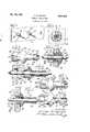
- Fig. l is a perspective View of a work piece or panel having strain-relief grommets of the type contemplated hereby mounted thereon;
- Fig. 2 is an enlarged end View of one of the grommets as viewed from the rear of Fig. 1;
- Fig. 3 is a perspective view oi one form of the fastener contemplated by this invention.
- Fig. 4 is a cross-sectional view of the fastener shown in Fig. 1 preassembled on an electrical conductor and ready to be mounted on an apertured work part;
- Fig. 5 is a sectional View of the fastener shown in Fig. 4 after being preliminarily positioned on the apertured work piece;
- Fig. 6 is a sectional View of the fastener shown in Figs. e' and 5 in finally applied position with the stud portion of the fastener mounted in the work part and the electrical conductor grippingly engaged, said view being taken substantially along the line S- of Fig. 2;
- Fig. 7 shows a second embodiment of the invention wherein the grommet is provided with a resilient head member
- Fig. 8 shows still another embodiiient of the invention wherein a grommet of the type contemplated by this invention is designed to accept an electrical conductor through a sidewall ther-L of, eliminating the necessity of threading the conductor longitudinally through the grommet member.
- a strain-relief, electrically non-conductive grominet for accommodating elongated members, such for example as electrical conductors, including a hollow rivet section consisting of a shank, a head at one extremity oi said thank for engaging one side oi an apertured Work piece, a transversely yieldahle portion at the other end of said shani-z adapted to 'oe expanded into engagement with the opposite side of the aforen mentioned apertured work piece, and a tubular section normally projecting from the head ezitremity of said rivet section in position to oe driven into telescopic association therewith, :aid tubular section normally having substantially constant internal and external diameters throughout a substantial portion oi' its length, the outer extremity of said tubular section fiaring radially outwardly and axially severed to assure inward flexing and consequent impingement of the inner periphery thereof with a coinplenientary elongated member as an incident to telescopic association of the rivet and
- a grommet oi the type described in claim i wherein the rivet and tubular sections are pro-- vided with side ports communicatin" with their interiors and completely traversing their longitudinal axes, the port in the tubular section being circumferentially displaced from and c minuni4 eating with the port in the rivet section wheren by to permit lateral insertion of an clongaged member such as an electrical conductor through said port into the interior oi' the rivet and tubu lar sections.
- a groininet of the type described in claim l wherein the rivet and tubular seclions are provided with side ports communicating with their interiors and completely traversing their longitudinal axes whereby to permit lateral insertion of an elongated member such as an electrical conduotor through said ports into interior o3? the rivet and tubular sections.
- a strain-relief grommet for accommodating elongated members comprising a hollovvv rivet section including a shank, ahead at one extremity of said shank ior engaging one side of an apertured workpiece, a transversely yieldahie portion at the other end ci said shank adapted to he panded into engagement with the oppos" e side of an apertured workpiece, and a tubular section normally projecting from the head of said rivet section in position to be driven into teiescopi association therewith, said rivet and tubular sections having side ports communicating with their interiors and completely traversing their longitudinal axes whereby to permit lateral insertion of an elongated member through said ports into the interior of the rivet and tubular sections.
Landscapes
- Engineering & Computer Science (AREA)
- Architecture (AREA)
- Civil Engineering (AREA)
- Structural Engineering (AREA)
- Insulating Bodies (AREA)
Description
Dec. 29, 1953 G. M. RAPATA STRAIN-RELIEF GROMMET Filed Jan. 11. 1952 Patented Dec. 29, 1953 STRAIN-RELIEF GROMMET George M. Rapata, Chicago, Ill., assignor to Illinois Tool Works, Chicago, Ill., a corporation of Illinois Application January 11, 1952, Serial No. 266,018
7 Claims.
This invention relates generally to strain-relief grommets and more particularly to grommets of the type made of electrically non-conductive material to support, insulate, and otherwise protect electrical conductors, rods, or tubes extending through apertured panels.
The type of strain-relief grommet or gripping insulator contemplated by this invention may be quickly and easily applied from one side of an apertured panel. The design of this fastener permits it to be preassembled on a panel and thereafter the conductor threaded through the grommet before the grommet is finally positioned relative to the panel on which it is mounted. The grommet contemplated by this invention is adapted to grippingly engage the conductor passing therethrough which eliminates movement of the electrical conductor relative to the panel as well as wear of the insulation if such is used on the conductor.
It is an important object of this invention to provide a comparativeli7 small unitary fastener which is designed to be applied from one side of an apertured panel and grips and supports a conductor or the like in angular relation to the panel through which it passes.
It is one of the important objects of the present invention to provide a strain-relief grommet which may be preassembled within the aperture of a panel or work piece and thereafter expanded into tight fitting relation with resp-ect to the work piece and with respect to an elongated member such, for example, as an electrical conductor extending through and projecting from opposite extremities of the grommet.
More specically, the invention contemplates a strain-relief grommet of the type referred to above which, when it is expanded into tight tting relation with respect to a work panel, also contracts into tight grip-ping relation with respect to the periphery of the elongated work part.
, It is also an object of the present invention to provide a gronimet or fastener as set forth above, wherein the expansion of the grommet into tight fitting relation with respect to the panel, and the contraction thereof with respect to the elongated work part or conductor, may be accomplished by a single element driven into telescopic association with a hollow rivet section.
It is another object of this invention to provide a strain-relief grommet wherein the member which grips the outer periphery of the conductor also serves as means for expanding the rivet portion of the fastener into permanently mounted position with respect to the panel.
It is still a further object of the present invention to provide a fastener of the type described which is adapted to be preassembled to an apertured panel prior to the passng of the conductor therethrough, thus enabling an operator to mount a plurality of these devices or grommets on a panel, thread Wires therethrough and thereafter secure the fasteners upon the panel in gripping engagement with the conductor.
1t is another object of dhe present invention to provide a fastener of the type described which is designed to be preassembled on a conductor or the like without first longitudinally feeding the conductor through a central passage in the fastener, and to this end the fastener is adapted to receive a conductor inserted laterally thereof.
Still another object or" this invention is to provide a strain-relief grommet which, when finally mounted on an apertured work part, substantially seals the aperture into which it is inserted.
These and other objects of the invention will be more apparent from a reading of the following description and a study of the accompanying drawings, wherein- Fig. l is a perspective View of a work piece or panel having strain-relief grommets of the type contemplated hereby mounted thereon;
Fig. 2 is an enlarged end View of one of the grommets as viewed from the rear of Fig. 1;
Fig. 3 is a perspective view oi one form of the fastener contemplated by this invention;
Fig. 4 is a cross-sectional view of the fastener shown in Fig. 1 preassembled on an electrical conductor and ready to be mounted on an apertured work part;
Fig. 5 is a sectional View of the fastener shown in Fig. 4 after being preliminarily positioned on the apertured work piece;
Fig. 6 is a sectional View of the fastener shown in Figs. e' and 5 in finally applied position with the stud portion of the fastener mounted in the work part and the electrical conductor grippingly engaged, said view being taken substantially along the line S- of Fig. 2;
Fig. 7 shows a second embodiment of the invention wherein the grommet is provided with a resilient head member; and
Fig. 8 shows still another embodiiient of the invention wherein a grommet of the type contemplated by this invention is designed to accept an electrical conductor through a sidewall ther-L of, eliminating the necessity of threading the conductor longitudinally through the grommet member.
, Referring to the drawings wherein like nufrom one of the resilient iingers 24h moves into registration with that portion or' the side opening 3@ in the rivet head ih. in this manner the lrey 33 serves to completely seal the rivet within the work aperture and the rivet head gives the appearance of being a complete or solid head. By having the side openings oi the rivet section and sleeve circumferentially displaced from each other, the registration of these openings with each other after the parts have been driven into final tightened position is prevented.. This assures trapping of the conductor or similar longitudinal element within the groinrnet structure. This type of strain-relief grommet is useful in applications where it is desirable to mount a fastener on a wire intermediate its ends. In other words, there are many instances where the end of the conductor is not accessible to the operator, and thus cannot be threaded through the grommet. In such instances the side opening arrange -c ment in the grommet serves a very useful purpose. While several embodiments of the invention have been shown, it should be understood that this invention is capable of other inodcations and changes without departing from the spirit and scope of the appended claims. Thus, the invention is not limited to the specific forms ilius.. trated herein, but should he limited only by the scope of the claims.
The invention is hereby claimed as follows:
l. A strain-relief, electrically non-conductive grominet for accommodating elongated members, such for example as electrical conductors, including a hollow rivet section consisting of a shank, a head at one extremity oi said thank for engaging one side oi an apertured Work piece, a transversely yieldahle portion at the other end of said shani-z adapted to 'oe expanded into engagement with the opposite side of the aforen mentioned apertured work piece, and a tubular section normally projecting from the head ezitremity of said rivet section in position to oe driven into telescopic association therewith, :aid tubular section normally having substantially constant internal and external diameters throughout a substantial portion oi' its length, the outer extremity of said tubular section fiaring radially outwardly and axially severed to assure inward flexing and consequent impingement of the inner periphery thereof with a coinplenientary elongated member as an incident to telescopic association of the rivet and tubular sections.
2. A groinmet or the type described in claim 1, wherein the head of the rivet section 'presents an annular shoulder having its clamping surface undercut to provide a seal when the fastener is mounted on an apertured Work part.
3. A grommet oi the type described in claim i, wherein the rivet and tubular sections are pro-- vided with side ports communicatin" with their interiors and completely traversing their longitudinal axes, the port in the tubular section being circumferentially displaced from and c minuni4 eating with the port in the rivet section wheren by to permit lateral insertion of an clongaged member such as an electrical conductor through said port into the interior oi' the rivet and tubu lar sections.
4. A groininet of the type described in claim l, wherein the rivet and tubular seclions are provided with side ports communicating with their interiors and completely traversing their longitudinal axes whereby to permit lateral insertion of an elongated member such as an electrical conduotor through said ports into interior o3? the rivet and tubular sections.
5. A grommet or the type described claim 2, wherein the head of the rivet recessed to assure yielding of the head and engagement ci the clamping surface with a workpiece provide a seal.
6. A strain-relief grommet for accommodating elongated members, comprising a hollovvv rivet section including a shank, ahead at one extremity of said shank ior engaging one side of an apertured workpiece, a transversely yieldahie portion at the other end ci said shank adapted to he panded into engagement with the oppos" e side of an apertured workpiece, and a tubular section normally projecting from the head of said rivet section in position to be driven into teiescopi association therewith, said rivet and tubular sections having side ports communicating with their interiors and completely traversing their longitudinal axes whereby to permit lateral insertion of an elongated member through said ports into the interior of the rivet and tubular sections.
'7. A grommet as deiined in claim 6, which includes a key member extending radially from the outer end of said tubular section and insertable in the portion of the side port extending through the head of the rivet section When the rivet and tubular sections are moved into telescopic relationship.
GEORGE M. RAPATA.
References Cited in the file of this patent UNITED STATES PATENTS Number Name Date 2,462,287 Kearns June 18, 19.45 2,424,602 De Swart July 29, i947 2,530,258 Marsan Nov. 14, i) 2,592,130 Erb et al. Apr. 8, 1952
Priority Applications (1)
| Application Number | Priority Date | Filing Date | Title |
|---|---|---|---|
| US266018A US2664458A (en) | 1952-01-11 | 1952-01-11 | Strain-relief grommet |
Applications Claiming Priority (1)
| Application Number | Priority Date | Filing Date | Title |
|---|---|---|---|
| US266018A US2664458A (en) | 1952-01-11 | 1952-01-11 | Strain-relief grommet |
Publications (1)
| Publication Number | Publication Date |
|---|---|
| US2664458A true US2664458A (en) | 1953-12-29 |
Family
ID=23012834
Family Applications (1)
| Application Number | Title | Priority Date | Filing Date |
|---|---|---|---|
| US266018A Expired - Lifetime US2664458A (en) | 1952-01-11 | 1952-01-11 | Strain-relief grommet |
Country Status (1)
| Country | Link |
|---|---|
| US (1) | US2664458A (en) |
Cited By (46)
| Publication number | Priority date | Publication date | Assignee | Title |
|---|---|---|---|---|
| US2741747A (en) * | 1954-03-11 | 1956-04-10 | Gen Motors Corp | Panel lamp socket of insulation having opening engaging resilient fingers |
| US2755110A (en) * | 1954-02-12 | 1956-07-17 | Arthur W Jacobs | Synthetic resin gland type coupling for tubes |
| US2830485A (en) * | 1956-04-19 | 1958-04-15 | Illinois Tool Works | Tubular rivet formed from strip metallic stock |
| US2894426A (en) * | 1954-01-05 | 1959-07-14 | Illinois Tool Works | Stud fastener with frictional gripping means |
| US2941439A (en) * | 1957-01-30 | 1960-06-21 | Illinois Tool Works | Rivet and integral expander pin connected thereto by area of limited cross section |
| US2956605A (en) * | 1953-03-05 | 1960-10-18 | Illinois Tool Works | Plastic screw receiving insert having a circular body and a polygonal head |
| US2968207A (en) * | 1957-11-25 | 1961-01-17 | Howard A Flogaus | Blind rivet which permits cold flow of shank material |
| US3022973A (en) * | 1958-07-22 | 1962-02-27 | Tektronix Inc | Support device |
| US3027494A (en) * | 1960-12-16 | 1962-03-27 | Illinois Tool Works | Mounting means for electrical components |
| US3076668A (en) * | 1957-10-09 | 1963-02-05 | Famely Max | Fittings for retaining cylindrical members in place |
| US3099057A (en) * | 1961-07-24 | 1963-07-30 | Boeing Co | Self-retaining fasteners |
| US3164418A (en) * | 1957-08-19 | 1965-01-05 | Illinois Tool Works | Plastic roller |
| US3190605A (en) * | 1962-10-16 | 1965-06-22 | Gilbert Daniel | Combination hanger hook and display plastic bags |
| US3197556A (en) * | 1962-01-17 | 1965-07-27 | Simon Johann Hans | Insulating sleeve for guiding cables through a wall opening |
| US3242298A (en) * | 1962-09-17 | 1966-03-22 | Cutler Hammer Inc | Mounting means for operator of electric switch |
| DE1269839B (en) * | 1959-06-22 | 1968-06-06 | Illinois Tool Works | Fuse element |
| US3434746A (en) * | 1966-08-10 | 1969-03-25 | Amp Inc | Flexible tube coupling |
| US3518359A (en) * | 1968-03-28 | 1970-06-30 | Amp Inc | Heat-shrinkable sealing and strain-relief fittings for electrical cables |
| US3800068A (en) * | 1972-01-10 | 1974-03-26 | Belden Corp | Strain relief |
| US3844588A (en) * | 1972-06-21 | 1974-10-29 | Ingersoll Rand Co | Condenser tube support plate insert |
| US3993277A (en) * | 1974-04-17 | 1976-11-23 | Itw Limited | Plastics fasteners |
| US4033535A (en) * | 1973-05-18 | 1977-07-05 | Eaton Corporation | Strain-relief bushing |
| US4034944A (en) * | 1973-05-18 | 1977-07-12 | Eaton Corporation | Strain-relief bushing |
| DE2750026C2 (en) * | 1977-11-09 | 1982-04-01 | Helmut 7293 Pfalzgrafenweiler Genkinger | Floor distributors for heating systems |
| US4385777A (en) * | 1980-06-02 | 1983-05-31 | The Logsdon Foundation | Decorative escutcheon capable of inhibiting the propagation of noise |
| US4494719A (en) * | 1982-02-15 | 1985-01-22 | Societe Anonyme D.B.A. | Device for fixing a flexible conduit to a panel |
| US4998938A (en) * | 1988-06-09 | 1991-03-12 | Neurodynamics, Inc. | Removable skull mounted work platform and method of assembling same |
| US5037326A (en) * | 1990-06-12 | 1991-08-06 | General Motors Corporation | Sealed grommet mounting for lamp socket |
| US5806139A (en) * | 1996-04-24 | 1998-09-15 | Hi-Lex Corporation | Grommet assembly |
| US5872335A (en) * | 1997-06-30 | 1999-02-16 | Heyco Products, Inc. | 90 degree sealing nut |
| DE20107949U1 (en) | 2001-05-11 | 2001-10-04 | Böllhoff GmbH, 33649 Bielefeld | Plug-in coupling |
| US6300569B1 (en) | 1997-02-13 | 2001-10-09 | Heyco Products, Inc. | 90° sealing nut |
| US6447166B1 (en) | 2000-05-24 | 2002-09-10 | Illinois Tool Works Inc. | Linear bushing |
| USD484784S1 (en) | 2003-02-14 | 2004-01-06 | Illinois Tool Works Inc. | Anti-rattle rod guide clip |
| US20060113731A1 (en) * | 2004-11-17 | 2006-06-01 | Franco Stocchiero | Sealing ring to be applied to connection holes of cells of an accumulator |
| US20090236848A1 (en) * | 2008-03-19 | 2009-09-24 | Foreman Keith G | Bidirectional pipe grip sleeve |
| US20110233969A1 (en) * | 2008-12-19 | 2011-09-29 | Honda Motor Co., Ltd. | Vehicle wiring structure |
| US20110304165A1 (en) * | 2010-06-14 | 2011-12-15 | Gm Global Technology Operations, Inc. | Door Rod and Clip Assembly |
| US8661614B2 (en) | 2011-08-17 | 2014-03-04 | Symmetry Medical Manufacturing, Inc. | Grommet device with flexible bowed members and methods of using thereof |
| US8701246B2 (en) | 2011-09-14 | 2014-04-22 | Symmetry Medical Manufacturing, Inc. | Removable grommet device and method of using thereof |
| US8739363B2 (en) | 2011-09-14 | 2014-06-03 | Symmetry Medical Manufacturing, Inc. | Removable grommet device with enlargeable slit and method thereof |
| US9277967B2 (en) | 2011-09-14 | 2016-03-08 | Symmetry Medical Manufacturing, Inc. | Universally-sized grommet device and method thereof |
| US9371948B2 (en) | 2013-08-14 | 2016-06-21 | Heyco, Inc. | Liquid-tight connector |
| US9853437B2 (en) | 2014-03-28 | 2017-12-26 | Heyco Inc. | Liquid-tight strain relief |
| US20220034261A1 (en) * | 2020-07-28 | 2022-02-03 | General Electric Company | Combustor cap assembly having impingement plate with cooling tubes |
| US11543128B2 (en) | 2020-07-28 | 2023-01-03 | General Electric Company | Impingement plate with cooling tubes and related insert for impingement plate |
Citations (4)
| Publication number | Priority date | Publication date | Assignee | Title |
|---|---|---|---|---|
| US2402287A (en) * | 1943-09-27 | 1946-06-18 | Shellmar Products Corp | Plastic rivet |
| US2424602A (en) * | 1945-05-15 | 1947-07-29 | Shellmar Products Corp | Flush rivet |
| US2530258A (en) * | 1945-07-23 | 1950-11-14 | Frank J Papes | Self-locking insulating bushing for electric conductors |
| US2592130A (en) * | 1946-10-24 | 1952-04-08 | Elastic Stop Nut Corp | Insulating fastening device |
-
1952
- 1952-01-11 US US266018A patent/US2664458A/en not_active Expired - Lifetime
Patent Citations (4)
| Publication number | Priority date | Publication date | Assignee | Title |
|---|---|---|---|---|
| US2402287A (en) * | 1943-09-27 | 1946-06-18 | Shellmar Products Corp | Plastic rivet |
| US2424602A (en) * | 1945-05-15 | 1947-07-29 | Shellmar Products Corp | Flush rivet |
| US2530258A (en) * | 1945-07-23 | 1950-11-14 | Frank J Papes | Self-locking insulating bushing for electric conductors |
| US2592130A (en) * | 1946-10-24 | 1952-04-08 | Elastic Stop Nut Corp | Insulating fastening device |
Cited By (50)
| Publication number | Priority date | Publication date | Assignee | Title |
|---|---|---|---|---|
| US2956605A (en) * | 1953-03-05 | 1960-10-18 | Illinois Tool Works | Plastic screw receiving insert having a circular body and a polygonal head |
| US2894426A (en) * | 1954-01-05 | 1959-07-14 | Illinois Tool Works | Stud fastener with frictional gripping means |
| US2755110A (en) * | 1954-02-12 | 1956-07-17 | Arthur W Jacobs | Synthetic resin gland type coupling for tubes |
| US2741747A (en) * | 1954-03-11 | 1956-04-10 | Gen Motors Corp | Panel lamp socket of insulation having opening engaging resilient fingers |
| US2830485A (en) * | 1956-04-19 | 1958-04-15 | Illinois Tool Works | Tubular rivet formed from strip metallic stock |
| US2941439A (en) * | 1957-01-30 | 1960-06-21 | Illinois Tool Works | Rivet and integral expander pin connected thereto by area of limited cross section |
| US3164418A (en) * | 1957-08-19 | 1965-01-05 | Illinois Tool Works | Plastic roller |
| US3076668A (en) * | 1957-10-09 | 1963-02-05 | Famely Max | Fittings for retaining cylindrical members in place |
| US2968207A (en) * | 1957-11-25 | 1961-01-17 | Howard A Flogaus | Blind rivet which permits cold flow of shank material |
| US3022973A (en) * | 1958-07-22 | 1962-02-27 | Tektronix Inc | Support device |
| DE1269839B (en) * | 1959-06-22 | 1968-06-06 | Illinois Tool Works | Fuse element |
| US3027494A (en) * | 1960-12-16 | 1962-03-27 | Illinois Tool Works | Mounting means for electrical components |
| US3099057A (en) * | 1961-07-24 | 1963-07-30 | Boeing Co | Self-retaining fasteners |
| US3197556A (en) * | 1962-01-17 | 1965-07-27 | Simon Johann Hans | Insulating sleeve for guiding cables through a wall opening |
| US3242298A (en) * | 1962-09-17 | 1966-03-22 | Cutler Hammer Inc | Mounting means for operator of electric switch |
| US3190605A (en) * | 1962-10-16 | 1965-06-22 | Gilbert Daniel | Combination hanger hook and display plastic bags |
| US3434746A (en) * | 1966-08-10 | 1969-03-25 | Amp Inc | Flexible tube coupling |
| US3518359A (en) * | 1968-03-28 | 1970-06-30 | Amp Inc | Heat-shrinkable sealing and strain-relief fittings for electrical cables |
| US3800068A (en) * | 1972-01-10 | 1974-03-26 | Belden Corp | Strain relief |
| US3844588A (en) * | 1972-06-21 | 1974-10-29 | Ingersoll Rand Co | Condenser tube support plate insert |
| US4033535A (en) * | 1973-05-18 | 1977-07-05 | Eaton Corporation | Strain-relief bushing |
| US4034944A (en) * | 1973-05-18 | 1977-07-12 | Eaton Corporation | Strain-relief bushing |
| US3993277A (en) * | 1974-04-17 | 1976-11-23 | Itw Limited | Plastics fasteners |
| DE2750026C2 (en) * | 1977-11-09 | 1982-04-01 | Helmut 7293 Pfalzgrafenweiler Genkinger | Floor distributors for heating systems |
| US4385777A (en) * | 1980-06-02 | 1983-05-31 | The Logsdon Foundation | Decorative escutcheon capable of inhibiting the propagation of noise |
| US4494719A (en) * | 1982-02-15 | 1985-01-22 | Societe Anonyme D.B.A. | Device for fixing a flexible conduit to a panel |
| US4998938A (en) * | 1988-06-09 | 1991-03-12 | Neurodynamics, Inc. | Removable skull mounted work platform and method of assembling same |
| US5037326A (en) * | 1990-06-12 | 1991-08-06 | General Motors Corporation | Sealed grommet mounting for lamp socket |
| US5806139A (en) * | 1996-04-24 | 1998-09-15 | Hi-Lex Corporation | Grommet assembly |
| US6300569B1 (en) | 1997-02-13 | 2001-10-09 | Heyco Products, Inc. | 90° sealing nut |
| US5872335A (en) * | 1997-06-30 | 1999-02-16 | Heyco Products, Inc. | 90 degree sealing nut |
| US6447166B1 (en) | 2000-05-24 | 2002-09-10 | Illinois Tool Works Inc. | Linear bushing |
| DE20107949U1 (en) | 2001-05-11 | 2001-10-04 | Böllhoff GmbH, 33649 Bielefeld | Plug-in coupling |
| USD484784S1 (en) | 2003-02-14 | 2004-01-06 | Illinois Tool Works Inc. | Anti-rattle rod guide clip |
| US20060113731A1 (en) * | 2004-11-17 | 2006-06-01 | Franco Stocchiero | Sealing ring to be applied to connection holes of cells of an accumulator |
| US20090236848A1 (en) * | 2008-03-19 | 2009-09-24 | Foreman Keith G | Bidirectional pipe grip sleeve |
| US8444216B2 (en) * | 2008-12-19 | 2013-05-21 | Honda Motor Co., Ltd. | Vehicle wiring structure |
| US20110233969A1 (en) * | 2008-12-19 | 2011-09-29 | Honda Motor Co., Ltd. | Vehicle wiring structure |
| US20110304165A1 (en) * | 2010-06-14 | 2011-12-15 | Gm Global Technology Operations, Inc. | Door Rod and Clip Assembly |
| US8661614B2 (en) | 2011-08-17 | 2014-03-04 | Symmetry Medical Manufacturing, Inc. | Grommet device with flexible bowed members and methods of using thereof |
| US8701246B2 (en) | 2011-09-14 | 2014-04-22 | Symmetry Medical Manufacturing, Inc. | Removable grommet device and method of using thereof |
| US8739363B2 (en) | 2011-09-14 | 2014-06-03 | Symmetry Medical Manufacturing, Inc. | Removable grommet device with enlargeable slit and method thereof |
| US20140205494A1 (en) * | 2011-09-14 | 2014-07-24 | Symmetry Medical Manufacturing Inc. | Removable Grommet Device and Method of Using Thereof |
| US9038239B2 (en) * | 2011-09-14 | 2015-05-26 | Symmetry Medical Manufacturing, Inc. | Removable grommet device and method of using thereof |
| US9277967B2 (en) | 2011-09-14 | 2016-03-08 | Symmetry Medical Manufacturing, Inc. | Universally-sized grommet device and method thereof |
| US9371948B2 (en) | 2013-08-14 | 2016-06-21 | Heyco, Inc. | Liquid-tight connector |
| US9853437B2 (en) | 2014-03-28 | 2017-12-26 | Heyco Inc. | Liquid-tight strain relief |
| US20220034261A1 (en) * | 2020-07-28 | 2022-02-03 | General Electric Company | Combustor cap assembly having impingement plate with cooling tubes |
| US11499480B2 (en) * | 2020-07-28 | 2022-11-15 | General Electric Company | Combustor cap assembly having impingement plate with cooling tubes |
| US11543128B2 (en) | 2020-07-28 | 2023-01-03 | General Electric Company | Impingement plate with cooling tubes and related insert for impingement plate |
Similar Documents
| Publication | Publication Date | Title |
|---|---|---|
| US2664458A (en) | Strain-relief grommet | |
| US5820323A (en) | Weld-on fastener, welding equipment for the welding of the fastener, and arrangement for the fastening of an assembly part to the weldable fastener | |
| US6114630A (en) | Snap in cable connector | |
| US2816949A (en) | Armoured cable mounting | |
| US3381981A (en) | End fittings for flexible conduits | |
| US2857176A (en) | Tube coupling with nut-actuated clamping and sealing means | |
| KR920020781A (en) | Connector for high voltage electric cable connection | |
| US3118644A (en) | Wiring fasteners | |
| US1678350A (en) | Electric clamp connecter | |
| US2555292A (en) | Fastener | |
| US3205759A (en) | Two-piece molding fastener | |
| US2351858A (en) | Securing clamp | |
| US4373112A (en) | Cable holder | |
| US3746373A (en) | Connector for electrical conduits | |
| US2295899A (en) | Method of manufacturing conductor terminals | |
| US2768232A (en) | Cable and ground wire clamp for electrical outlet boxes | |
| US3292132A (en) | Test jack for panel mounting | |
| US3377609A (en) | Replacement connector | |
| US4021092A (en) | Electrical connector | |
| US20190323637A1 (en) | Electrical conduit coupler | |
| US2424804A (en) | Pass-through insulator | |
| US1706973A (en) | Connecter for hollow electrical conductors or tubes | |
| US830501A (en) | Protecting-bushing for electric-circuit wires. | |
| KR20190097283A (en) | Cable connector assembly | |
| US2437111A (en) | Cable clamp |