EP3033262B1 - Stabilisierte blende für ein logistikmodul - Google Patents
Stabilisierte blende für ein logistikmodul Download PDFInfo
- Publication number
- EP3033262B1 EP3033262B1 EP14796154.4A EP14796154A EP3033262B1 EP 3033262 B1 EP3033262 B1 EP 3033262B1 EP 14796154 A EP14796154 A EP 14796154A EP 3033262 B1 EP3033262 B1 EP 3033262B1
- Authority
- EP
- European Patent Office
- Prior art keywords
- fall
- rod
- prevention flap
- fall arrest
- flap
- Prior art date
- Legal status (The legal status is an assumption and is not a legal conclusion. Google has not performed a legal analysis and makes no representation as to the accuracy of the status listed.)
- Active
Links
Images


Classifications
-
- B—PERFORMING OPERATIONS; TRANSPORTING
- B62—LAND VEHICLES FOR TRAVELLING OTHERWISE THAN ON RAILS
- B62B—HAND-PROPELLED VEHICLES, e.g. HAND CARTS OR PERAMBULATORS; SLEDGES
- B62B3/00—Hand carts having more than one axis carrying transport wheels; Steering devices therefor; Equipment therefor
- B62B3/002—Hand carts having more than one axis carrying transport wheels; Steering devices therefor; Equipment therefor characterised by a rectangular shape, involving sidewalls or racks
- B62B3/004—Details of doors or cover lids
-
- B—PERFORMING OPERATIONS; TRANSPORTING
- B62—LAND VEHICLES FOR TRAVELLING OTHERWISE THAN ON RAILS
- B62B—HAND-PROPELLED VEHICLES, e.g. HAND CARTS OR PERAMBULATORS; SLEDGES
- B62B5/00—Accessories or details specially adapted for hand carts
- B62B5/0013—Protection covers, e.g. against rain
Definitions
- One aspect of the invention relates to a fall arrest flap capable of sealing, at least partially, an opening left between two walls of a logistics module.
- the logistics module can be, for example, in the form of a trolley or a container able to store, at least temporarily, goods.
- the fall protection component can therefore find applications in stores as well as in logistics centers to supply stores.
- Other aspects of the invention relate to an assembly comprising the fall arrest flap and a logistics module.
- the patent publication EP 1 428 763 A1 discloses a goods storage cart comprising a base and two vertical side panels mounted thereon.
- the carriage is provided with a fall arrest flap to cover one side of the carriage defined between these two sides.
- this side is an opening defined between two walls in the form of side panels.
- the fall arrest flap can close this opening. More specifically, the fall arrest flap is fixed on both sides so that the fall arrest flap is openable, or even removable. An operator can thus conveniently open, or temporarily remove, the fall arrest flap to place goods in the cart, or to remove goods from the cart.
- the patent publication DE 10 2012 000077 B3 discloses a carriage, in particular a CC-type container for transporting plants and flowers.
- the carriage comprises a rectangular base provided with four uprights defining a storage space accessible by two longitudinal sides and two narrow sides.
- the carriage is provided with a set of rolling shutters, a shutter for each of the aforementioned sides. The shutter can be moved vertically, downwards or upwards to close the storage space and to provide access to the storage space.
- the fall arrest flap When a fall arrest flap closes an opening left between two walls of a logistics module, the fall arrest flap should be sufficiently stretched horizontally and vertically. These horizontal and vertical tensions allow the fall arrest flap to effectively prevent a fall of goods stored in the logistics module, for example, during a transport. That is, horizontal and vertical stresses contribute significantly to a fall arrest function.
- a sufficiently large horizontal tension can be obtained by means of elements fixing the fall arrest flap to one and the other of the two walls of the logistics module so that the opening left between these walls is closed.
- a vertical tension can be obtained by means of stop elements arranged on one and the other of the two walls. These stop elements may be constituted, for example, by sleepers when the two walls are in the form of side panels.
- the stop elements must be positioned at a height corresponding to that of the fall arrest flap. This condition can be met by designing a fall arrest flap specifically for a logistics module.
- this other logistics module does not include stop elements properly positioned relative to the fall arrest flap. In this case, the fall arrest flap in lack of vertical tension slumps, that is to say, collapses partially. This can seriously affect the fall arrest function.
- a fall arrest flap is as defined in claim 1.
- Such a fall arrest flap makes it easy to obtain a desired vertical tension for the fall arrest function, even if the fall arrest flap is affixed to a logistics module for which it was not designed. Just insert a wand into each wand holder. The rod cooperates with its support in order to avoid slackening of the fall arrest flap when the fall arrest flap is affixed to the logistics module. This therefore allows a versatile use of the fall arrest flap: the fall arrest flap can be applied to different types of logistics modules having, for example, different types of side panels.
- a logistic unit is as defined in claim 12.
- the figure 1 schematically illustrates, by a front view, a fall arrest flap 100.
- This fall arrest flap 100 can be affixed to a logistics module, such as a trolley or a container, to close an opening left between two walls of the logistics module.
- the fall arrest flap 100 comprises two longitudinal edges: a left edge 101 and a straight edge 102. These two longitudinal edges 101, 102 are oriented vertically when the fall arrest flap 100 is affixed to a logistics module.
- the fall arrest flap 100 comprises two transverse edges: a high edge 103 and a low edge 104. These two transverse edges 103, 104 are oriented horizontally when the fall arrest flap 100 is affixed to a logistics module.
- the left edge 101 is provided with three locked fastening tapes: a high locked fastener tape 105, a median locked fastener tape 106, and a low locked fastener tape 107.
- the high locked fastener tape 105 is near the edge 103 of the fall arrest flap 100.
- the lower locked fastening tape 107 is located near the low edge 104 of the fall arrest flap 100.
- the median locked fastening tape 106 is approximately midway between the two transverse edges 103, 104 above.
- the three locked fastening tapes 105, 106, 107 can be folded over themselves in a loop, and this in a fixed manner, around an amount of a logistics module.
- the three locked fastening tapes 105, 106, 107 can be looped by means of, for example, rivets.
- the three locked fastening tapes 105, 106, 107 then lock the left edge 101 of the fall arrest flap 100 to the relevant amount of the logistics module. This amount can thus constitute a pivot axis for the fall arrest flap 100.
- the straight edge 102 includes three removable fastening tapes: a top removable fastener tape 108, a medial removable fastener tape 109, and a bottom removable fastener tape 110.
- the top removable fastener tape 108 is near the top edge 103. of the fall arrest flap 100.
- the lower removable fastening tape 110 is located near the low edge 104 of the fall arrest flap 100.
- the fastening tape Removable median 109 is located approximately midway between the two transverse 103, 104 supra.
- the three removable fastening tapes 107, 108, 109 may be self-gripping tapes.
- the three removable fastening tapes 108, 109, 110 enable the right edge 102 of the fall arrest flap 100 to be removably attached to an amount of a logistics module.
- the fall arrest flap 100 can pivot about an amount to which the left edge 101 of the fall arrest flap 100 is fixed as described in the foregoing.
- the fall arrest flap 100 can close an opening between these amounts to prevent a fall of goods.
- the fall arrest flap 100 comprises a relatively light cover sheet 111, which will typically be flexible.
- the sealing sheet 111 may be formed from a plastic material such as, for example, based on polyethylene, based on polyvinyl chloride, frequently designated by the acronym PVC, or any other suitable plastic material.
- the sealing sheet 111 may comprise a plastic weave provided with a coating of the same kind.
- the fall arrest flap 100 further comprises three reinforcing strips: a high reinforcing strip 112, a median reinforcing strip 113, and a low reinforcing strip 114. These reinforcing strips are similar to straps.
- the three reinforcement strips 112, 113, 114 impart rigidity to the fall arrest flap 100 so that it resists to thrusts that goods may exert on the fall arrest flap 100, in particular on the blanking sheet 111.
- the figure 1 illustrates an exemplary embodiment where the three locked fastening tapes 105, 106, 107 and the three removable fastening tapes 108, 109, 110 constitute extensions of the three reinforcing strips 112, 113, 114. More specifically, the fastening tape
- the top lock 105 is an extension at a left end of the upper reinforcing strip 112.
- the top removable fastening tape 108 is an extension at a right end of the upper reinforcing strip 112.
- the medial locked fastener tape 106 constitutes a extension at a left end of the medial reinforcing strip 113.
- the medial removable fastening tape 109 constitutes an extension at a right end of the median reinforcing strip 113.
- the lower locked fastening tape 107 constitutes an extension at a left end of the median reinforcing strip 113.
- the lower removable fastening tape 110 constitutes an extension at a right end of the low reinforcing strip 114.
- the upper reinforcing strip 112 constitutes a reinforcement in an area where the top locked locking tape 105 is located.
- the medial reinforcing strip 113 provides reinforcement in an area where the medial locked fastener tape 106 is located, and the low reinforcement strip 114 provides reinforcement in an area where the low locked fastener tape 107 is located.
- the fall arrest flap 100 is provided with two rod holders: a left rod support 115 and a straight rod support 116. These rod holders are very schematically represented in FIG. figure 1 .
- the left rod support 115 is located near the left edge 101 of the fall arrest flap 100.
- the right rod support 116 is located near the right edge 102 of the fall arrest flap 100.
- the left rod support 115 comprises two ends: a high end 117 and a low end 118.
- the high end 117 is at the high edge 103 of the fall arrest flap 100.
- the low end 118 is at the low edge 104 of the fall arrest flap. 100.
- the straight rod support 116 comprises two similar ends: a high end 119 at the high edge 103 of the fall arrest flap 100 and a low end 120 at the low edge 104 of the fall arrest flap 100.
- the left stick support 115 may retain a rod removably. That is, an operator can insert a rod into the left rod support 115.
- the left rod support 115 holds the rod, which is thus integral with the fall arrest flap 100.
- the left rod support 115 holds the rod in a vertical orientation when the fall arrest flap 100 is affixed to a logistics module.
- An operator may also remove the wand from the left wand holder 115, for example, if the operator believes that his use is not necessary or for any other reason.
- the foregoing remarks also apply to the straight rod support 116, which may similarly retain a rod removably.
- a rod to be inserted into the left rod support 115 advantageously has a length which corresponds to a distance between the two ends 117, 118 of the left rod support 115.
- the rod extends between the two transverse edges 103, 104 of the fall arrest flap 100, near the left edge 101 thereof.
- the remarks also apply to a rod to be inserted in the straight rod support 116. This rod also extends advantageously between the two transverse edges 103, 104 of the fall arrest flap 100, near the right edge 102 thereof.
- a set of identical rods, at least in length, may be provided for the fall arrest flap 100 illustrated in FIG. figure 1 . Any wand of this set can be inserted into the left wand holder 115. Similarly, any wand of this set can be inserted into the right wand holder 116. This is because, in the illustrated example, the distance between the two ends 117, 118 of the left rod support 115 and the distance between the two ends 119, 120 of the straight rod support 116 are identical, or at least substantially identical. These distances may be considered identical if, for example, they do not differ less than one percent from each other.
- the fall arrest flap 100 may comprise a pocket 121 on a front face as illustrated by FIG. figure 1 .
- a label, or any other form of plane support, may be inserted in the pouch 121.
- the label may include an indication relating to the goods stored in a logistics module on which the fall arrest flap 100 illustrated in FIG. figure 1 is affixed.
- the figure 2 schematically illustrates, in a perspective view, a portion of the fall arrest flap 100 illustrated in FIG. figure 1 .
- the part illustrated at figure 2 is located near the left edge 101 and the top edge 103.
- An upper portion of the left stick support 115, including its top end 117, is visible at the figure 2 .
- the figure 2 further illustrates a wand 200 being introduced into the left wand holder 115.
- the left rod support 115 comprises a sheath 201 in which the rod 200 can be introduced as shown in FIG. figure 2 .
- the sheath 201 is formed by a left portion 202 of the shutter sheet 111 folded longitudinally on itself.
- a border 203 of this folded portion 202 is attached to a main portion of the sealing sheet 111, which extends between the two longitudinal edges 101, 102 of the fall arrest flap 100 This attachment may comprise, for example, seams.
- the sheath 201 is dimensioned so that the rod 200 is tightly gripped in the sheath 201 after its introduction. Therefore, there is a longitudinal friction between the rod 200 and the sheath 201. This friction avoids movements of the rod 200 relative to the sheath 201, and vice versa.
- the wand 200 thus prevents the fall arrest flap 100 from collapsing and collapsing, even locally.
- the figure 2 illustrates an embodiment which does not include a stop at the upper end 117 of the left stick support 115 visible to the figure 2 .
- a stop is not necessary because the sheath 201 encloses the rod 200 sufficiently closely. Nevertheless, it is possible to provide a stop at the upper end 117 of the rod support 115.
- a stop is advantageously provided at the lower end 118 of the left rod support 115, visible at the figure 1 .
- the 200 stick illustrated at figure 2 comprises a U-shaped section. This shape gives the rod 200 good rigidity, good performance.
- the wand 200 can thus be relatively light.
- the wand 200 may be formed of, for example, plastics material or metal.
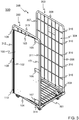
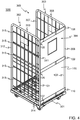
- the figures 3 and 4 schematically illustrate a logistics module 300, seen in perspective, provided with the fall arrest flap 100 illustrated in FIG. figure 1 .
- the figure 3 illustrates the logistics module 300 in an open state.
- the fall arrest flap 100 is in the open position.
- the figure 4 illustrates the logistics module 300 in a closed state.
- the fall arrest flap 100 is in the closed position.
- the logistics module 300 illustrated at figure 3 is in the form of a carriage and will thus be designated "carriage 300" in what follows for reasons of convenience.
- the carriage 300 comprises a base 301 mainly formed by a frame in which a grid has been arranged.
- the carriage 300 further comprises two walls in the form of sidewalls: a sideboard which will be designated left sideboard 302 in the following, and another sideboard which will be designated right sideboard 303.
- the carriage 300 has two openings left between these two side panels 302, 303: an opening which will be designated front opening 304 in the following, and another opening which will be designated rear opening 305.
- the right side wall 303 comprises a pair of peripheral posts, namely a front peripheral post 306 and a rear peripheral post 307, and a pair of peripheral cross members, namely a high peripheral cross member 308 and a low cross member 309. These peripheral elements constitute together a frame of the right side wall 303.
- Intermediate cross members 310 are disposed between an intermediate section of the front peripheral post 306 and an intermediate section of the rear peripheral post 307. Both intermediate sections extend between two ends of the peripheral amount in question as illustrated by the figure 3 .
- the left sideboard 302 has a similar structure, visible at the figure 4 .
- the left side wall 302 comprises a frame formed by a front peripheral post 311, a rear peripheral post 312, a high peripheral cross member 313, and a low cross member 314.
- Intermediate cross members 315 are disposed between an intermediate section of the front peripheral post 311 and an intermediate section of the rear peripheral pillar 312.
- the three locked fastening tapes 105, 106, 107 of the fall arrest flap 100 are folded over themselves in a loop, and this in a fixed manner, around the front peripheral pillar 311 of the left side wall 302 of the carriage 300.
- the three fastening tapes locked 105, 106, 107 then lock the left edge 101 of the fall arrest flap 100 to this front peripheral post 311.
- the front peripheral post 311 of the left side rail 302 thus constitutes a pivot axis for the fall arrest flap 100.
- the three removable fastening tapes 108, 109, 110 of the fall arrest flap 100 removably fix the edge right 102 of the fall arrest flap 100 to the rear peripheral amount 312 of the left side wall 302 of the carriage 300.
- the fall arrest flap 100 alongside the left side wall 302.
- the fall arrest flap 100 is integral with the side wall left 302.
- the three removable fastening tapes 108, 109, 110 removably attach the right edge 102 of the fall arrest flap 100 to the front peripheral upright 306 of the right side wall 303 of the carriage 300.
- the fall arrest flap 100 closes the front opening 304 of the carriage 300 left between the two sides 302, 303 thereof.
- the fall arrest flap 100 provides a fall arrest function as the same name. Goods placed in the carriage 300 are retained in the latter, thanks to the fall arrest flap 100 in its closed position. During transport, a commodity can move towards the front opening 304 of the carriage 300. This merchandise then abuts against the fall arrest flap 100, which closes this opening before 304, thus avoiding a fall of the merchandise in question .
- the lower locked fastening tape 107 of the fall arrest flap 100 rests on the lower peripheral cross member 314 of the left side wall 302 by gravity. That is, when the fall arrest flap 100 is lifted slightly, then released, the low locked fastener tape 107, as well as the low edge 104 of the fall arrest flap 100, abut against the low cross member 314.
- the cross member Low device 314 thus constitutes a low abutment element on the front peripheral amount 311 of the left side wall 302, to which the fall arrest flap 100 is fixed in a locked manner.
- the top locked locking tape 105 does not rest on any crosspiece of the left sideboard 302. This is due to the fact that the fall arrest flap 100 has not been adapted specifically to the carriage 300. More specifically, the fall arrest flap 100 a a height which exceeds a distance between the lower cross member 314, which constitutes the bottom stop member, and the highest intermediate cross member 315 of the left side wall 302.
- the fall arrest flap 100 shown in figure 3 comprises no rod support, and therefore does not include any rod extending between the two transverse edges 103, 104 of the fall arrest flap 100.
- the fall arrest flap 100 would tend to collapse by lack of vertical tension. This slumping, collapse, can cause the fall arrest flap 100 does not hold sufficiently good to maintain goods in the cart 300. There is a risk of falling goods.
- This fall arrest flap 100 corresponds to the fall arrest component 100 shown in figure 1 , and described with reference to this figure.
- This fall arrest flap 100 comprises the left rod support 115 which extends between the two transverse edges 103, 104 of the fall arrest flap 100.
- the left rod support 115 therefore has a length corresponding to the height of the fall arrest flap 100. This is the case likewise for the right stick support 116.
- both rods have respective lengths respectively to that of the left rod support 115 and that of the right rod support 116.
- the length of the rods is identical, or almost identical, and corresponds to the height of the fall arrest flap 100.
- the two rod supports 115, 116 and the rods introduced into them avoid a slackening of the fall arrest flap 100 which could adversely affect the fall arrest function thereof.
- the aforementioned elements ensure a good performance of the fall arrest flap 100, even if it is not specifically adapted to the carriage 300 on which the fall arrest flap 100 is affixed.
- the rod introduced into the left rod support 115 cooperates with this support so that these elements ensure a vertical tension of the fall arrest flap 100 near the left edge 101 thereof.
- the left rod support 115 comprises a sheath tightly enclosing the rod inserted into this sheath. It exists therefore a longitudinal friction between the rod and the sheath, which ensures the vertical tension.
- the rod inserted in the straight rod support 116 cooperates in the same manner with this support so that these elements ensure a vertical tension of the fall arrest flap 100 near the right edge 102 thereof.
- the invention can be advantageously applied to many products and logistics processes.
- the invention can, in principle, be applied to all types of logistics modules having an opening left between two walls.
- a cart as illustrated in figures 3 and 4 is only one example of such a logistics module.
- the logistics module can also be in the form of a container devoid of wheels.
- An opening to be closed by a fall arrest flap can be located between two walls arranged in the same plane, in which the opening is also located.
- the term "logistics module" must be interpreted broadly. This term embraces any entity in which objects may be placed for storage or transport purposes.
- a wand holder need not include a sheath, which can tightly grip a wand inserted therein.
- the wand support may comprise a relatively wide sheath relative to a wand so that there is relatively little longitudinal friction between these elements.
- the wand can be sandwiched between two stops located at two opposite ends of the sheath. Thus, these elements exert a vertical tension on the fall arrest flap.
- Yet another embodiment can be achieved by partially or even completely removing the sheath.
- a fall arrest flap in accordance with the invention may, in principle, comprise any number of rod supports.
- a wand support can be added to the fall arrest flap shown at figure 1 .
- This additional wand holder may be, for example, halfway between the left wand holder 115 and the right wand holder 116.
- a wand holder need not be arranged to retain a wand removably, such as the left wand holder 115 shown in FIG. figure 2 .
- the wand support may be in the form of a permanently closed sheath after insertion of a wand. This final closure can be done by means of, for example, a rivet.
- a fall arrest flap according to the invention does not necessarily have to include reinforcing strips as illustrated in FIG. figure 1 .
- One embodiment may even be totally devoid of reinforcement strips in the case where, for example, the fall arrest flap has a good rigidity so that the fall arrest flap can withstand a pressure exerted by a merchandise against the flap Anti fall.
- a hook may constitute a fastening means.
- the hook may be provided with a form of lock so that the fastener is locked.
Landscapes
- Engineering & Computer Science (AREA)
- Chemical & Material Sciences (AREA)
- Combustion & Propulsion (AREA)
- Transportation (AREA)
- Mechanical Engineering (AREA)
- Packages (AREA)
- Handcart (AREA)
Claims (13)
- Sturzschutzklappe (100), die geeignet ist, um mindestens teilweise eine Öffnung (304) zu verschließen, die zwischen zwei Wänden (302, 303) eines Logistikmoduls (300) belassen ist, das geeignet ist, mindestens vorübergehend Waren zu lagern, wobei die Sturzschutzklappe zwei Längsränder (101, 102) umfasst, von welchen einer mit einer verriegelten Befestigungsvorrichtungen (105, 106, 107) versehen ist, um die Sturzschutzklappe an einem Ständer (311) einer der zwei Wände derart zu befestigen, dass dieser Ständer eine Schwenkachse für die Sturzschutzklappe bilden kann, wobei der andere Längsrand (102) mit einer abnehmbaren Befestigungsvorrichtung (108, 109, 110) versehen ist,
dadurch gekennzeichnet, dass die Sturzschutzklappe Folgendes umfasst:- zwei Leistenträger (115, 116), von welchen sich einer nahe einem der zwei Längsränder der Sturzschutzklappe befindet, während sich der andere Leistenträger nahe dem anderen Längsrand befindet,- zwei Leisten (200), von welchen eine in einen der zwei Leistenträger eingeführt wurde, während die andere Leiste in den anderen Leistenträger eingeführt wurde, wobei beide Leisten jeweils mit dem einen und dem anderen Leistenträger zusammenwirken, um ein Absacken der Sturzschutzklappe zu vermeiden, wenn die Sturzschutzklappe auf dem Logistikmodul eingefügt ist. - Sturzschutzklappe nach Anspruch 1, wobei einer der zwei Leistenträger (115, 116) eine Hülse (201) umfasst, in der eine der zwei Leisten (200) eingeführt wurde, wobei der andere Leistenträger auch eine Hülse umfasst, in die der andere Leistenträger eingeführt wurde.
- Sturzschutzklappe nach Anspruch 2, wobei die Hülse eines der zwei Leistenträger (115, 116) und die Hülse des anderen Leistenträgers jeweils nach dem jeweiligen Einführen der einen und der anderen Leiste endgültig geschlossen sind.
- Sturzschutzklappe nach Anspruch 2, wobei die Hülse (201) des Leistenträgers (105), die nahe dem Längsrand (101) liegt, der mit einer verriegelten Befestigungsvorrichtung (105, 106, 107) versehen ist, mindestens teilweise aus einem Verschlussblatt (111) gebildet ist, das längs auf sich gefaltet ist, wobei das Verschlussblatt bemessen ist, um die Öffnung (304), die zwischen den zwei Wänden (302, 303) des Logistikmoduls (300) belassen ist, mindestens teilweise zu verschließen.
- Sturzschutzklappe nach einem der Ansprüche 2 und 4, wobei die Hülse des einen der zwei Leistenträger (115, 116) und die Hülse des anderen Leistenträgers bemessen sind, um jeweils die eine und die andere Leiste eng einzuschließen.
- Sturzschutzklappe nach einem der Ansprüche 1, 2, 4 und 5, wobei der eine und der andere Leistenträger (115, 116) angepasst sind, um jeweils die eine und die andere Leiste abnehmbar zurückzuhalten.
- Sturzschutzklappe nach einem der Ansprüche 1, 2 und 4 bis 6, wobei einer der zwei Leistenträger (115, 116) ein Ende (117) umfasst, das an einem oberen Querrand (103) der Sturzschutzklappe liegt, und ein anderes Ende (118), das an einem unteren Querrand (104) der Sturzschutzklappe derart liegt, dass sich die Leiste (200), die in diesen Leistenträger eingeführt ist, zwischen diesen zwei Querrändern der Sturzschutzklappe erstrecken kann, wobei der andere Leistenträger auch ein Ende (119) umfasst, das an dem oberen Querrand der Sturzschutzklappe liegt, und ein anderes Ende (120) das an dem unteren Querrand der Sturzschutzklappe liegt.
- Sturzschutzklappe nach einem der Ansprüche 1, 2 und 4 bis 7, die eine Verstärkung (112, 113, 114) in einer Zone umfasst, in der die verriegelte Befestigungsvorrichtung (105, 106, 107) liegt.
- Sturzschutzklappe nach Anspruch 8, die ein Verstärkungsband (112, 113, 114) umfasst, das sich zwischen der verriegelten Befestigungsvorrichtung (105, 106, 107) und der abnehmbaren Befestigungsvorrichtung (108, 109, 110) befindet.
- Sturzschutzklappe nach einem der Ansprüche 1, 2 und 4 bis 9, wobei die eine und die andere Leiste jeweils eine Länge haben, die einem Abstand zwischen zwei Enden (117, 118) jeweils des einen und des anderen Leistenträgers (115, 116) entspricht.
- Sturzschutzklappe nach einem der Ansprüche 1, 2 und 4 bis 10, wobei mindestens eine Leiste ein Profil in U-Form umfasst.
- Logistikanordnung, die Folgendes umfasst:- ein Logistikmodul (300), das eine Öffnung (304) aufweist, die zwischen zwei Wänden (302, 303) des Logistikmoduls belassen ist, und- eine Sturzschutzklappe (100) nach einem der Ansprüche 1 bis 11, wobei die Sturzschutzklappe bemessen ist, um diese Öffnung mindestens teilweise zu verschließen.
- Anordnung nach Anspruch 12, wobei mindestens eine der zwei Wände (302, 303) die Form einer Klappwand hat, die Zwischenquerträger (305, 315) umfasst, die sich zwischen einem Zwischenabschnitt eines peripheren Ständers (311) der Klappwand und einem Zwischenabschnitt eines anderen peripheren Ständers (312) der Klappwand erstrecken, wobei die Sturzschutzklappe (100) eine Höhe aufweist, die größer ist als ein Abstand zwischen dem höchsten Zwischenquerträger und einem unteren Anschlagelement (314) auf einem peripheren Ständer (311) der Klappwand, wobei sich der eine und der andere Leistenträger (115, 116) und die eine und die andere Leiste (200) zwischen zwei Querrändern (103, 104) der Sturzschutzklappe erstrecken.
Priority Applications (1)
| Application Number | Priority Date | Filing Date | Title |
|---|---|---|---|
| EP18177794.7A EP3395644B1 (de) | 2013-08-12 | 2014-08-07 | Sturzschutzklappe für logistikmodul |
Applications Claiming Priority (2)
| Application Number | Priority Date | Filing Date | Title |
|---|---|---|---|
| FR1357953A FR3009534B1 (fr) | 2013-08-12 | 2013-08-12 | Volet antichute pour module logistique |
| PCT/FR2014/052064 WO2015022466A1 (fr) | 2013-08-12 | 2014-08-07 | Volet antichute pour module logistique |
Related Child Applications (1)
| Application Number | Title | Priority Date | Filing Date |
|---|---|---|---|
| EP18177794.7A Division EP3395644B1 (de) | 2013-08-12 | 2014-08-07 | Sturzschutzklappe für logistikmodul |
Publications (2)
| Publication Number | Publication Date |
|---|---|
| EP3033262A1 EP3033262A1 (de) | 2016-06-22 |
| EP3033262B1 true EP3033262B1 (de) | 2018-06-27 |
Family
ID=49753316
Family Applications (2)
| Application Number | Title | Priority Date | Filing Date |
|---|---|---|---|
| EP14796154.4A Active EP3033262B1 (de) | 2013-08-12 | 2014-08-07 | Stabilisierte blende für ein logistikmodul |
| EP18177794.7A Active EP3395644B1 (de) | 2013-08-12 | 2014-08-07 | Sturzschutzklappe für logistikmodul |
Family Applications After (1)
| Application Number | Title | Priority Date | Filing Date |
|---|---|---|---|
| EP18177794.7A Active EP3395644B1 (de) | 2013-08-12 | 2014-08-07 | Sturzschutzklappe für logistikmodul |
Country Status (4)
| Country | Link |
|---|---|
| EP (2) | EP3033262B1 (de) |
| DK (1) | DK3033262T3 (de) |
| FR (1) | FR3009534B1 (de) |
| WO (1) | WO2015022466A1 (de) |
Cited By (1)
| Publication number | Priority date | Publication date | Assignee | Title |
|---|---|---|---|---|
| EP3825207A1 (de) * | 2019-11-20 | 2021-05-26 | Pilsl Transportgeräte GmbH | Rollbehälter mit schutzwand |
Families Citing this family (4)
| Publication number | Priority date | Publication date | Assignee | Title |
|---|---|---|---|---|
| EP3208176B1 (de) | 2016-02-19 | 2020-07-29 | Ythales Invest | Logistikmodul mit fallverhinderungsklappe |
| CN108455015B (zh) * | 2017-02-17 | 2021-03-05 | 伊泰勒斯投资公司 | 物流部件和用于储存的组合体 |
| CN108839697A (zh) * | 2018-07-09 | 2018-11-20 | 黄山市麦佰机械自动化有限公司 | 一种防止物件掉落的物料搬运设备 |
| AT524335B1 (de) * | 2020-10-28 | 2022-03-15 | Claudio Kratzmueller Mag | Transportsicherung zur Sicherung von Waren auf einem Rollbehälter |
Family Cites Families (11)
| Publication number | Priority date | Publication date | Assignee | Title |
|---|---|---|---|---|
| SE7809644L (sv) * | 1978-09-13 | 1980-03-14 | Metzeler Schaum Gmbh | Isolerhuv |
| US5226544A (en) | 1991-12-19 | 1993-07-13 | Amici Enterprises Inc. | Reusable pallet wrapper |
| EP0732249B1 (de) | 1995-03-11 | 1998-11-11 | Douglas Baird | Vorrichtung zum Schützen von Pflanzen |
| JP2004142811A (ja) | 2002-10-28 | 2004-05-20 | Eco System:Kk | 荷くずれ防止装置 |
| FR2848187B1 (fr) | 2002-12-09 | 2006-09-01 | Touraine Emballage Recyclage | Chariot de transport de marchandises comportant au moins un volet anti chute |
| WO2007142340A1 (ja) | 2006-06-09 | 2007-12-13 | Zerotechnos Co., Ltd. | 締付けバンド |
| CN101541639B (zh) | 2006-11-14 | 2011-02-16 | 爱碧世株式会社 | 装载物固定装置 |
| JP3137361U (ja) | 2007-09-10 | 2007-11-22 | 株式会社エコシステム | 荷崩れ防止ベルト |
| JP5363917B2 (ja) | 2008-09-04 | 2013-12-11 | 株式会社ティーディーエスコーポレーション | 荷崩れ防止シート |
| US8656968B2 (en) * | 2011-03-28 | 2014-02-25 | Han-Chun Lin | Snow protection device |
| DE102012000077B3 (de) * | 2012-01-04 | 2012-12-27 | Sebastian Sitek | Fahrbarer Transportwagen, insbesondere CC-Container, insbesondere zum Transport von Pflanzen und Blumen |
-
2013
- 2013-08-12 FR FR1357953A patent/FR3009534B1/fr active Active
-
2014
- 2014-08-07 WO PCT/FR2014/052064 patent/WO2015022466A1/fr not_active Ceased
- 2014-08-07 EP EP14796154.4A patent/EP3033262B1/de active Active
- 2014-08-07 EP EP18177794.7A patent/EP3395644B1/de active Active
- 2014-08-07 DK DK14796154.4T patent/DK3033262T3/en active
Non-Patent Citations (1)
| Title |
|---|
| None * |
Cited By (2)
| Publication number | Priority date | Publication date | Assignee | Title |
|---|---|---|---|---|
| EP3825207A1 (de) * | 2019-11-20 | 2021-05-26 | Pilsl Transportgeräte GmbH | Rollbehälter mit schutzwand |
| BE1027771B1 (de) * | 2019-11-20 | 2021-06-22 | Pilsl Transp Gmbh | Rollbehälter mit Schutzwand |
Also Published As
| Publication number | Publication date |
|---|---|
| EP3395644C0 (de) | 2025-10-08 |
| FR3009534B1 (fr) | 2016-10-21 |
| FR3009534A1 (fr) | 2015-02-13 |
| EP3395644B1 (de) | 2025-10-08 |
| WO2015022466A1 (fr) | 2015-02-19 |
| DK3033262T3 (en) | 2018-10-15 |
| EP3033262A1 (de) | 2016-06-22 |
| EP3395644A1 (de) | 2018-10-31 |
Similar Documents
| Publication | Publication Date | Title |
|---|---|---|
| EP3033262B1 (de) | Stabilisierte blende für ein logistikmodul | |
| EP0514278B1 (de) | Schuhaufhänger | |
| EP1428763B1 (de) | Transportwagen mit mindestens einer Abdeckung gegen das Herabfallen des Transportgutes | |
| EP3208176B1 (de) | Logistikmodul mit fallverhinderungsklappe | |
| FR2550071A1 (fr) | Dispositif d'emmagasinage et d'exposition | |
| EP3385145B1 (de) | Logistikmodul | |
| EP0912409B1 (de) | Vorrichtung zum transport und zur lagerung von langgestreckten elementen wie stossfänger | |
| EP0261012B1 (de) | Ordnungs- oder Transportvorrichtung für Gegenstände oder verschiedene Produkte | |
| EP3856607A1 (de) | Zusammenklappbares logistikmodul | |
| FR2530570A3 (fr) | Chariot libre-service emboitable avec porte-caisse | |
| CA3012860A1 (fr) | Container | |
| EP3000354B1 (de) | Vorrichtung zum Lagern von Gegenständen für Garage oder Ähnliches | |
| BE1023121A1 (fr) | Diviseuse de pâte avec grilles interchangeables | |
| EP0320319B1 (de) | Handwagen aus beweglichen Metallplatten für den Transport von verschiedenen Produkten | |
| FR2625360A1 (fr) | Support pour une pancarte de signalisation ou similaire devant etre apposee sur un element constitue par une grille metallique | |
| EP3242837B1 (de) | Logistikmodul | |
| EP3033261B1 (de) | Hybrid-einkaufswagen | |
| FR3103165A3 (fr) | Conteneur roulant avec paroi de protection | |
| FR3065448A1 (fr) | Chariot permettant notamment la collecte selective des dechets et leur stockage en vue de leur recyclage- ensemble de pieces associe | |
| FR2506829A1 (fr) | Portiere, notamment portiere a lanieres, destinee a fermer des porches, passages ou equivalents | |
| FR2918861A1 (fr) | Presentoir deployable. | |
| EP0827916A1 (de) | Vorrichtung zur Handhabung | |
| FR2992537A1 (fr) | Dispositif pour le guidage d'objets longs | |
| FR2666057A1 (fr) | Perfectionnement aux dispositifs d'accrochage d'une bache notamment sur un vehicule de transport. | |
| FR2563810A1 (fr) | Conteneur-presentoir, notamment pour boites d'oeufs. |
Legal Events
| Date | Code | Title | Description |
|---|---|---|---|
| PUAI | Public reference made under article 153(3) epc to a published international application that has entered the european phase |
Free format text: ORIGINAL CODE: 0009012 |
|
| 17P | Request for examination filed |
Effective date: 20160301 |
|
| AK | Designated contracting states |
Kind code of ref document: A1 Designated state(s): AL AT BE BG CH CY CZ DE DK EE ES FI FR GB GR HR HU IE IS IT LI LT LU LV MC MK MT NL NO PL PT RO RS SE SI SK SM TR |
|
| AX | Request for extension of the european patent |
Extension state: BA ME |
|
| DAX | Request for extension of the european patent (deleted) | ||
| STAA | Information on the status of an ep patent application or granted ep patent |
Free format text: STATUS: EXAMINATION IS IN PROGRESS |
|
| 17Q | First examination report despatched |
Effective date: 20170301 |
|
| GRAP | Despatch of communication of intention to grant a patent |
Free format text: ORIGINAL CODE: EPIDOSNIGR1 |
|
| STAA | Information on the status of an ep patent application or granted ep patent |
Free format text: STATUS: GRANT OF PATENT IS INTENDED |
|
| INTG | Intention to grant announced |
Effective date: 20171212 |
|
| RIN1 | Information on inventor provided before grant (corrected) |
Inventor name: CHERBONNIER, YVES |
|
| GRAS | Grant fee paid |
Free format text: ORIGINAL CODE: EPIDOSNIGR3 |
|
| GRAA | (expected) grant |
Free format text: ORIGINAL CODE: 0009210 |
|
| STAA | Information on the status of an ep patent application or granted ep patent |
Free format text: STATUS: THE PATENT HAS BEEN GRANTED |
|
| AK | Designated contracting states |
Kind code of ref document: B1 Designated state(s): AL AT BE BG CH CY CZ DE DK EE ES FI FR GB GR HR HU IE IS IT LI LT LU LV MC MK MT NL NO PL PT RO RS SE SI SK SM TR |
|
| REG | Reference to a national code |
Ref country code: GB Ref legal event code: FG4D Free format text: NOT ENGLISH |
|
| REG | Reference to a national code |
Ref country code: AT Ref legal event code: REF Ref document number: 1012034 Country of ref document: AT Kind code of ref document: T Effective date: 20180715 |
|
| REG | Reference to a national code |
Ref country code: IE Ref legal event code: FG4D Free format text: LANGUAGE OF EP DOCUMENT: FRENCH |
|
| REG | Reference to a national code |
Ref country code: DE Ref legal event code: R096 Ref document number: 602014027610 Country of ref document: DE |
|
| REG | Reference to a national code |
Ref country code: FR Ref legal event code: PLFP Year of fee payment: 5 |
|
| REG | Reference to a national code |
Ref country code: DK Ref legal event code: T3 Effective date: 20181008 |
|
| REG | Reference to a national code |
Ref country code: NL Ref legal event code: FP |
|
| PG25 | Lapsed in a contracting state [announced via postgrant information from national office to epo] |
Ref country code: NO Free format text: LAPSE BECAUSE OF FAILURE TO SUBMIT A TRANSLATION OF THE DESCRIPTION OR TO PAY THE FEE WITHIN THE PRESCRIBED TIME-LIMIT Effective date: 20180927 Ref country code: LT Free format text: LAPSE BECAUSE OF FAILURE TO SUBMIT A TRANSLATION OF THE DESCRIPTION OR TO PAY THE FEE WITHIN THE PRESCRIBED TIME-LIMIT Effective date: 20180627 Ref country code: SE Free format text: LAPSE BECAUSE OF FAILURE TO SUBMIT A TRANSLATION OF THE DESCRIPTION OR TO PAY THE FEE WITHIN THE PRESCRIBED TIME-LIMIT Effective date: 20180627 Ref country code: BG Free format text: LAPSE BECAUSE OF FAILURE TO SUBMIT A TRANSLATION OF THE DESCRIPTION OR TO PAY THE FEE WITHIN THE PRESCRIBED TIME-LIMIT Effective date: 20180927 Ref country code: FI Free format text: LAPSE BECAUSE OF FAILURE TO SUBMIT A TRANSLATION OF THE DESCRIPTION OR TO PAY THE FEE WITHIN THE PRESCRIBED TIME-LIMIT Effective date: 20180627 |
|
| REG | Reference to a national code |
Ref country code: LT Ref legal event code: MG4D |
|
| PG25 | Lapsed in a contracting state [announced via postgrant information from national office to epo] |
Ref country code: GR Free format text: LAPSE BECAUSE OF FAILURE TO SUBMIT A TRANSLATION OF THE DESCRIPTION OR TO PAY THE FEE WITHIN THE PRESCRIBED TIME-LIMIT Effective date: 20180928 Ref country code: LV Free format text: LAPSE BECAUSE OF FAILURE TO SUBMIT A TRANSLATION OF THE DESCRIPTION OR TO PAY THE FEE WITHIN THE PRESCRIBED TIME-LIMIT Effective date: 20180627 Ref country code: RS Free format text: LAPSE BECAUSE OF FAILURE TO SUBMIT A TRANSLATION OF THE DESCRIPTION OR TO PAY THE FEE WITHIN THE PRESCRIBED TIME-LIMIT Effective date: 20180627 Ref country code: HR Free format text: LAPSE BECAUSE OF FAILURE TO SUBMIT A TRANSLATION OF THE DESCRIPTION OR TO PAY THE FEE WITHIN THE PRESCRIBED TIME-LIMIT Effective date: 20180627 |
|
| REG | Reference to a national code |
Ref country code: AT Ref legal event code: MK05 Ref document number: 1012034 Country of ref document: AT Kind code of ref document: T Effective date: 20180627 |
|
| PG25 | Lapsed in a contracting state [announced via postgrant information from national office to epo] |
Ref country code: EE Free format text: LAPSE BECAUSE OF FAILURE TO SUBMIT A TRANSLATION OF THE DESCRIPTION OR TO PAY THE FEE WITHIN THE PRESCRIBED TIME-LIMIT Effective date: 20180627 Ref country code: IS Free format text: LAPSE BECAUSE OF FAILURE TO SUBMIT A TRANSLATION OF THE DESCRIPTION OR TO PAY THE FEE WITHIN THE PRESCRIBED TIME-LIMIT Effective date: 20181027 Ref country code: AT Free format text: LAPSE BECAUSE OF FAILURE TO SUBMIT A TRANSLATION OF THE DESCRIPTION OR TO PAY THE FEE WITHIN THE PRESCRIBED TIME-LIMIT Effective date: 20180627 Ref country code: PL Free format text: LAPSE BECAUSE OF FAILURE TO SUBMIT A TRANSLATION OF THE DESCRIPTION OR TO PAY THE FEE WITHIN THE PRESCRIBED TIME-LIMIT Effective date: 20180627 Ref country code: CZ Free format text: LAPSE BECAUSE OF FAILURE TO SUBMIT A TRANSLATION OF THE DESCRIPTION OR TO PAY THE FEE WITHIN THE PRESCRIBED TIME-LIMIT Effective date: 20180627 Ref country code: RO Free format text: LAPSE BECAUSE OF FAILURE TO SUBMIT A TRANSLATION OF THE DESCRIPTION OR TO PAY THE FEE WITHIN THE PRESCRIBED TIME-LIMIT Effective date: 20180627 Ref country code: SK Free format text: LAPSE BECAUSE OF FAILURE TO SUBMIT A TRANSLATION OF THE DESCRIPTION OR TO PAY THE FEE WITHIN THE PRESCRIBED TIME-LIMIT Effective date: 20180627 |
|
| PG25 | Lapsed in a contracting state [announced via postgrant information from national office to epo] |
Ref country code: ES Free format text: LAPSE BECAUSE OF FAILURE TO SUBMIT A TRANSLATION OF THE DESCRIPTION OR TO PAY THE FEE WITHIN THE PRESCRIBED TIME-LIMIT Effective date: 20180627 Ref country code: IT Free format text: LAPSE BECAUSE OF FAILURE TO SUBMIT A TRANSLATION OF THE DESCRIPTION OR TO PAY THE FEE WITHIN THE PRESCRIBED TIME-LIMIT Effective date: 20180627 Ref country code: SM Free format text: LAPSE BECAUSE OF FAILURE TO SUBMIT A TRANSLATION OF THE DESCRIPTION OR TO PAY THE FEE WITHIN THE PRESCRIBED TIME-LIMIT Effective date: 20180627 |
|
| REG | Reference to a national code |
Ref country code: DE Ref legal event code: R097 Ref document number: 602014027610 Country of ref document: DE |
|
| PG25 | Lapsed in a contracting state [announced via postgrant information from national office to epo] |
Ref country code: MC Free format text: LAPSE BECAUSE OF FAILURE TO SUBMIT A TRANSLATION OF THE DESCRIPTION OR TO PAY THE FEE WITHIN THE PRESCRIBED TIME-LIMIT Effective date: 20180627 |
|
| PLBE | No opposition filed within time limit |
Free format text: ORIGINAL CODE: 0009261 |
|
| STAA | Information on the status of an ep patent application or granted ep patent |
Free format text: STATUS: NO OPPOSITION FILED WITHIN TIME LIMIT |
|
| REG | Reference to a national code |
Ref country code: IE Ref legal event code: MM4A |
|
| 26N | No opposition filed |
Effective date: 20190328 |
|
| PG25 | Lapsed in a contracting state [announced via postgrant information from national office to epo] |
Ref country code: IE Free format text: LAPSE BECAUSE OF NON-PAYMENT OF DUE FEES Effective date: 20180807 |
|
| PG25 | Lapsed in a contracting state [announced via postgrant information from national office to epo] |
Ref country code: SI Free format text: LAPSE BECAUSE OF FAILURE TO SUBMIT A TRANSLATION OF THE DESCRIPTION OR TO PAY THE FEE WITHIN THE PRESCRIBED TIME-LIMIT Effective date: 20180627 |
|
| PG25 | Lapsed in a contracting state [announced via postgrant information from national office to epo] |
Ref country code: AL Free format text: LAPSE BECAUSE OF FAILURE TO SUBMIT A TRANSLATION OF THE DESCRIPTION OR TO PAY THE FEE WITHIN THE PRESCRIBED TIME-LIMIT Effective date: 20180627 |
|
| PG25 | Lapsed in a contracting state [announced via postgrant information from national office to epo] |
Ref country code: MT Free format text: LAPSE BECAUSE OF FAILURE TO SUBMIT A TRANSLATION OF THE DESCRIPTION OR TO PAY THE FEE WITHIN THE PRESCRIBED TIME-LIMIT Effective date: 20180627 |
|
| PG25 | Lapsed in a contracting state [announced via postgrant information from national office to epo] |
Ref country code: TR Free format text: LAPSE BECAUSE OF FAILURE TO SUBMIT A TRANSLATION OF THE DESCRIPTION OR TO PAY THE FEE WITHIN THE PRESCRIBED TIME-LIMIT Effective date: 20180627 |
|
| PG25 | Lapsed in a contracting state [announced via postgrant information from national office to epo] |
Ref country code: PT Free format text: LAPSE BECAUSE OF FAILURE TO SUBMIT A TRANSLATION OF THE DESCRIPTION OR TO PAY THE FEE WITHIN THE PRESCRIBED TIME-LIMIT Effective date: 20180627 |
|
| PG25 | Lapsed in a contracting state [announced via postgrant information from national office to epo] |
Ref country code: HU Free format text: LAPSE BECAUSE OF FAILURE TO SUBMIT A TRANSLATION OF THE DESCRIPTION OR TO PAY THE FEE WITHIN THE PRESCRIBED TIME-LIMIT; INVALID AB INITIO Effective date: 20140807 Ref country code: CY Free format text: LAPSE BECAUSE OF FAILURE TO SUBMIT A TRANSLATION OF THE DESCRIPTION OR TO PAY THE FEE WITHIN THE PRESCRIBED TIME-LIMIT Effective date: 20180627 Ref country code: MK Free format text: LAPSE BECAUSE OF NON-PAYMENT OF DUE FEES Effective date: 20180627 |
|
| PGFP | Annual fee paid to national office [announced via postgrant information from national office to epo] |
Ref country code: LU Payment date: 20250825 Year of fee payment: 12 |
|
| PGFP | Annual fee paid to national office [announced via postgrant information from national office to epo] |
Ref country code: DK Payment date: 20250823 Year of fee payment: 12 |
|
| PGFP | Annual fee paid to national office [announced via postgrant information from national office to epo] |
Ref country code: NL Payment date: 20250901 Year of fee payment: 12 |
|
| PGFP | Annual fee paid to national office [announced via postgrant information from national office to epo] |
Ref country code: BE Payment date: 20250901 Year of fee payment: 12 Ref country code: GB Payment date: 20250901 Year of fee payment: 12 |
|
| PGFP | Annual fee paid to national office [announced via postgrant information from national office to epo] |
Ref country code: FR Payment date: 20250901 Year of fee payment: 12 |
|
| REG | Reference to a national code |
Ref country code: CH Ref legal event code: U11 Free format text: ST27 STATUS EVENT CODE: U-0-0-U10-U11 (AS PROVIDED BY THE NATIONAL OFFICE) Effective date: 20251110 |
|
| PGFP | Annual fee paid to national office [announced via postgrant information from national office to epo] |
Ref country code: DE Payment date: 20251030 Year of fee payment: 12 |
|
| PGFP | Annual fee paid to national office [announced via postgrant information from national office to epo] |
Ref country code: CH Payment date: 20251110 Year of fee payment: 12 |