EP3032710B1 - Rotating electrical machine - Google Patents
Rotating electrical machine Download PDFInfo
- Publication number
- EP3032710B1 EP3032710B1 EP14835348.5A EP14835348A EP3032710B1 EP 3032710 B1 EP3032710 B1 EP 3032710B1 EP 14835348 A EP14835348 A EP 14835348A EP 3032710 B1 EP3032710 B1 EP 3032710B1
- Authority
- EP
- European Patent Office
- Prior art keywords
- slot liner
- slot
- inclined surface
- insulating member
- stator core
- Prior art date
- Legal status (The legal status is an assumption and is not a legal conclusion. Google has not performed a legal analysis and makes no representation as to the accuracy of the status listed.)
- Active
Links
Images


Classifications
-
- H—ELECTRICITY
- H02—GENERATION; CONVERSION OR DISTRIBUTION OF ELECTRIC POWER
- H02K—DYNAMO-ELECTRIC MACHINES
- H02K3/00—Details of windings
- H02K3/32—Windings characterised by the shape, form or construction of the insulation
- H02K3/34—Windings characterised by the shape, form or construction of the insulation between conductors or between conductor and core, e.g. slot insulation
- H02K3/345—Windings characterised by the shape, form or construction of the insulation between conductors or between conductor and core, e.g. slot insulation between conductor and core, e.g. slot insulation
Definitions
- the present invention relates to a rotating machine.
- the hybrid car and the electric car are based on the premise that they are motor-driven by an inverter.
- driving voltage of the motor-driving inverter is increased, in the stator coil of the segment-coil-winding technique, insulating paper (slot liner) is inserted in between segment coil/stator core and between different phase coils in the segment winding in the slot to secure electrical insulation of the stator core and between coil phases (see PTL 1).
- An insulator having a convex end for facilitating the insertion into a slot of a coil is described in WO2013/008568 A1 .
- An insulator having a concave end for facilitating the insertion of a winding is described in D1 JP 2002 165421 A . Further insulator having respective end sections are described in US 4 247 978 A , JP 2013 143819 A and DE 10 2012 001487 .
- the present invention provides a rotating machine having the features defined in claim 1.
- a further preferred embodiment is defined in claim 2.
- each of the embodiment and Comparative Example is for a stator core composed of a laminated core of a lamination thickness of 90 mm of a punched electromagnetic steel place corresponding to JIS 35A300 grade in which an outer diameter is 245 mm, an inner diameter is 200 mm and the number of slots is 72 for a hybrid car driving motor of 3-phase 12-poles to which a segment-coil-winding technique of rated driving voltage 300 Vdc-current 400 Arms is applied.
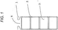
- FIG. 1 illustrates an interior configuration of a slot in a stator core of a hybrid car driving motor used in this embodiment and Comparative Example.
- Segment coils 3 formed from rectangular enameled wire are used as the stator core (winding). Since the rectangular segment coils 3 are densely accommodated in a slot 4, the slot 4 is of a substantially rectangular shape having a constant width, and four segment coils 3 forming the stator coil are inserted into the slot 4.
- a slot liner 2 is an insulating member used for insulation against the stator core 1 and for insulation between different phase coils.
- the slot liner 2 is placed in the slot 4 such that the slot liner 2 extends in an axial direction of a core of the stator core 1 which is a depth direction of a paper sheet of FIG. 1 .
- the present invention is based on the premise that a conventional slot liner having a flat slot liner end is used, a rectangular insulating line coated with a polyamidimide insulating layer having a thickness of 0.05 mm is used on a rectangular conductor having a short side of 2.4 mm, a long side of 3.3 mm and corner beveling radius of 0.3 mm.
- Insulating paper of a three layered structure of aramid/PET/aramid having a thickness of 0.17 mm is formed into a rectangular tube shape and is used as the slot liner.
- a width of the slot, a depth of a parallel portion, and a cross section area in the slot are 4.14 mm, 12.0 mm and 52.0 mm2, respectively, and a packing factor of coils is 60.3%.
- the present invention was applied to this stator core, and it was checked whether a stator core having high packing factor of coils could be manufactured.
- a rectangular insulating line coated with a polyamidimide insulating layer having a 0.05 mm was used on a rectangular conductor having a short side of 2.53 mm, a long side of 3.6 mm and a corner beveling radius of 0.3 mm.
- Placement of the slot liner was the same as that shown in FIG. 1 , and the slot liner was formed from insulating paper having the same configuration and the same thickness.
- the packing factor of coils in the configuration in this slot is 69.5% which is increased by about 10% as compared with the conventional configuration.
- assembling performance of a segment coil formed from the rectangular insulating conductor and a stator core configured by the slot liner of the present invention were compared and considered in a car assembling line without changing a size of a trial stator core. More specifically, the generation number of insertion failures when the slot was inserted into the slot liner and when the segment coil was inserted into a slot liner were compared with each other, thereby evaluating possibility of manufacture of the stator cores.
- a length of the slot liner was 96 mm, and the slot liner lies off from both end surfaces of a core slot by 3 mm because a prevention layer against creeping discharge is provided between the stator core and the segment coil.
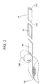
- FIG. 2 shows one example of a manufacturing process of a slot liner 14.
- sheet-shaped insulating paper is pulled out from a hoop of raw insulating paper 10 which is cut into a predetermined width, insulating paper 12 having a predetermined length is cut and bent-formed by a rotary cutter 110.
- the rotary cutter 110 is used for cutting the insulating paper into a constant length and according to this, a cut sectional surface inclines with respect to a sending direction of the insulating paper.
- the insulating paper 12 after the constant length cutting is subject to fold-bending, and it is formed into a rectangular tube shaped slot liner 14. Broken lines shown in the insulating paper 13 which is folded and bent show creases.
- FIG. 3 is diagram including a perspective view of the entire rectangular tube shaped slot liner 14 formed by a first manufacturing method shown in FIG. 2 , a perspective view in the vicinity of a convex end 141 and later-described concave end 142, and sectional view of the convex end 141 and the concave end 142.
- a perspective view of the entire rectangular tube shaped slot liner 14 in FIG. 3 is a perspective view of the rectangular tube shaped slot liner 14 as viewed from an insertion direction of the slot liner 14 into the stator core 1.
- the convex end 141 is formed on an insertion side end (stator core insertion side end) 14a of the slot liner 14 into the stator core 1.
- the concave end 142 is formed in an end (segment coil insertion side end) 14b of the slot liner 14 on a side opposite from the stator core insertion side end 14a.
- An arrow A shown in the vicinity of the convex end 141 shows an insertion direction of the slot liner 14 into the stator core 1.
- An arrow B shown in the vicinity of the concave end 142 shows an insertion direction of the segment coil 3 into the slot liner 14.
- the convex end 141 includes an inclined surface 141a for making it easy to insert the rectangular tube shaped slot liner 14 into the stator core 1.
- the inclined surface 141a is an oblique surface having an apex facing in an insertion direction into the stator core 1.
- an outer peripheral length of the rectangular tube shaped slot liner 14 in the convex end 141 becomes shorter from the segment coil insertion side end 14b toward the stator core insertion side end 14a. Since the inclined surface 141a inclines such that the convex end 141 is narrowed in the insertion direction into the stator core 1 in this manner, it becomes easy to insert the rectangular tube shaped slot liner 14 into the slot 4.
- the concave end 142 includes the inclined surface 142a for making it easy to insert the segment coil 3 into the rectangular tube shaped slot liner 14.
- the inclined surface 142a is an oblique surface having an apex facing the insertion direction into the stator core 1. Hence, an inner peripheral length of the rectangular tube shaped slot liner 14 in the concave end 142 becomes longer from the stator core insertion side end 14a toward the segment coil insertion side end 14b. Since the inclined surface 142a inclines such that an inner diameter of the rectangular tube shaped slot liner 14 in the concave end 142 becomes greater toward a direction opposite from the insertion direction of the segment coil 3 in this manner, it becomes easy to insert the segment coil 3 into the rectangular tube shaped slot liner 14.
- the inclined surface 141a and the inclined surface 142a are cut cross sections formed by being cut by the rotary cutter 110.
- the convex end 141 corresponds to a cut cross section on the side of the rotary cutter of the constant length cutting insulating paper 12 in FIG. 2
- the concave end 142 corresponds to a cut cross section opposite from the former cross section
- the convex end 141 and the concave end 142 have gradient angles with respect to the insertion direction of the slot liner.
- a gradient angle 133 of the convex end 141 of the rectangular tube shaped slot liner 14 is defined as a first gradient angle
- a gradient 134 of the concave end 142 is defined as a second gradient angle.
- the first gradient angle 133 is an angle formed between the inclined surface 141a and an inner peripheral surface of the rectangular tube shaped slot liner 14, and is an angle of a cross section of the convex end 141 when the rectangular tube shaped slot liner 14 is cut parallel to the insertion direction of the slot liner as shown in FIG. 3 .
- the second gradient angle 134 is an angle formed between the inclined surface 142a and the inner peripheral surface of the rectangular tube shaped slot liner 14, and is an angle of a cross section of the concave end 142 when the rectangular tube shaped slot liner 14 is cut parallel to the insertion direction of the slot liner as shown in FIG. 3 .
- the inclined surface 141a is for making it easy to insert the rectangular tube shaped slot liner 14 into the stator core 1.
- the first gradient angle 133 is an acute angle.
- the inclined surface 142a is for making it easy to insert the segment coil 3 into the rectangular tube shaped slot liner 14.
- the second gradient angle 134 is an obtuse angle. The first gradient angle 133 and the second gradient angle are different angles.
- the first gradient angle 133 is the acute angle
- the inclined surface 141a faces an outer side (inner side of slot 4) of the rectangular tube shaped slot liner 14. According to this configuration, the rectangular tube shaped slot liner 14 is easily inserted into the stator core 1. According to this, since it is possible to enhance the packing factor of coils as described above, it is possible to realize downsizing and weight reduction of the rotating machine.
- the second gradient angle 134 is the obtuse angle, and when the second gradient angle 134 is formed into the rectangular tube shape, the inclined surface 142a faces an inner side (toward segment coil 3) of the rectangular tube shaped slot liner 14. According to this configuration, it becomes easy to insert the segment coil 3 into the rectangular tube shaped slot liner 14. According to this, since it is possible to enhance the packing factor of coils as described above, it is possible to realize downsizing and weight reduction of the rotating machine.
- the first gradient angle 133 and the second gradient angle are a supplementary angle relation.
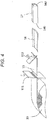
- FIG. 4 shows a second manufacturing method of the slot liner of the invention using shearing.
- insulating paper which is sent out from raw insulating paper 10 is cut into a constant length by a cutting blade 111 which moves perpendicularly to a sending-out direction of insulating paper.
- cut cross sections of both ends of the insulating paper (constant length insulating paper) 15 after constant length cutting are perpendicular to the sending-out direction of the insulating paper.
- a slide cutter 112 which is inclined with respect to the sending-out direction of the insulating paper.
- a cut cross section which is inclined with respect to the sending-out direction of the insulating paper is formed.
- the trimmed constant length insulating paper 15 is subjected to fold-bending like the first manufacturing method shown in FIG. 2 , and is formed into a rectangular tube shaped slot liner 17.
- FIG. 5 is a diagram including a perspective view of the entire rectangular tube shaped slot liner 17 formed by the second manufacturing method shown in FIG. 4 , and perspective view in the vicinity of the concave end 142 and a later-described flat end 140.
- the flat end 140 which is perpendicular to the insertion direction into the stator core 1 is formed on a stator core insertion side end 17a of the rectangular tube shaped slot liner 17.
- the concave end 142 is formed in a segment coil insertion side end 17b of the rectangular tube shaped slot liner 17.
- first gradient in the flat end 140 is 90°.
- FIG. 6 is a schematic diagram illustrating one example of a fold-bending method of insulating paper which is cut into a constant length.
- Roman numerals in FIG. 6 show a working sequence.
- Constant length cutting insulating paper 20 is conveyed onto bottom bending dies 22a and 22b, and is pushed and bent by a pressing die 21 and is placed into the bottom bending dies 22a and 22b (I). Thereafter, the constant length cutting insulating paper 20 is over-bent by movement of the bottom bending dies 22a and 22b in a central axial direction thereof and according to this, the constant length cutting insulating paper 20 is formed into a predetermined bending angle (90° in this case) (II).
- an upper portion-bending mandrel 23 is inserted (III), the upper shoulder parts are over-bent by a bending die for both upper shoulder parts 24a and 24b (IV). After the bending operation of the upper shoulder parts is completed, the over-bent upper shoulder parts are spring-backed, and the rectangular tube shaped slot liner is formed. The upper portion formed and bent mandrel 23 is recovered after the slot liner is formed, and the mandrel 23 is repeatedly used.
- the number of stator core assembly is one in each of Examples and Comparative Example.
- three kinds of, i.e., total six kinds of slot liners manufactured by the first and second manufacturing methods were used.
- slot liners manufactured in the first manufacturing method were used, and the first gradient angles 133 were set to 20°, 45° and 70°, and the second gradient angles 134 were set to 160°, 135° and 110°, respectively.
- the second gradient angle 134 is the supplementary angle with the first gradient angle 133.
- the gradient angles were set by adjusting a blade angle of the rotary cutter 110 shown in FIG. 2 .
- the gradient angles were set by adjusting an inclination angle of the slide cutter 112 shown in FIG. 4 .
- Comparative Example a conventional slot liner in which both the first and second gradient angles are 90° was used.
- the slot liner used in Comparative Example was manufactured by the second manufacturing method excluding a trimming process by the slide cutter 112.
- the number of insertion failures of slot liners is the number of insertion failures generated when the slot liners of Examples and Comparative Example are inserted into the slot 4.
- the number of insertion failures of the segment coils is the number of insertion failures generated when the segment coils 3 are inserted into the slot liners of Examples and Comparative Example which are inserted into the slot 4.
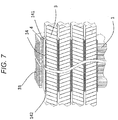
- FIG. 7 is a diagram illustrating an interior vertical sectional configuration of the slot of the stator assembled in the above-described Example 2, and illustrating a stator core innermost surface 31.
- Connecting portions 3a (see FIG. 8 ) of the segment coils 3 are placed on the side of the convex end 141 having the first gradient 133 of the slot liner, and a folded-back portion 3b (see FIG. 8 ) is placed on the side of the concave end 142 having the second gradient 134 of the slot liner.
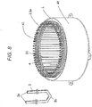
- FIG. 8 is a diagram including a perspective view of a stator 41 of the hybrid car motor to which the present invention is applied, and a perspective view of the segment coil 3 before it is inserted into the stator core 1.
- the stator 41 shown in FIG. 8 is manufactured by a segment-coil-winding technique having a high packing factor to which the present invention is applied.
- the stator 41 is fitted into a housing 44.
- the connecting portions 3a of the segment coil are inserted into the segment coil insertion side end 14b of the rectangular tube shaped slot liner 14 which has already been inserted into the stator core 1 (slot 4).
- the connecting portions 3a project outward of the stator core insertion side end 14a, and the folded-back portion 3b projects outward of the segment coil insertion side end 14b as described above.
- the connecting portions 3a are bent into predetermined shapes for connecting the segment coils to each other.
- the connecting portions 3a are bent into the predetermined shapes. Thereafter, the segment coils are welded to each other through the connecting portions 3a, and the stator 41 shown in FIG. 8 is electrically connected.
- the segment coil insertion side end 17b is provided with the concave end 142 and the stator core insertion side end 17a is not provided with the convex end 141.
- the present invention is not limited to this.
- a segment coil insertion side end 18b may not be provided with the concave end 142 and a stator core insertion side end 18a may be provided with the convex end 141.
- the stator core insertion side end 18a becomes the convex end 141 having first gradient and the segment coil insertion side end 18b becomes the flat end 140.
- both end surfaces in the sending-out direction generated by a cutting incline with respect to the sending-out direction can also be applied to the technique for cutting such that both end surfaces in the sending-out direction generated by cutting incline with respect to the sending-out direction.
- the rectangular tube shaped slot liner 14, 17, 18 was formed by bending after the raw insulating paper 10 is cut into the constant length in the embodiment.
- the forming method of the rectangular tube shaped slot liner is not limited to this, and it is possible to employ such a technique that insulating paper which is sent out from the hoop of raw insulating paper 10 is formed into the shape of the rectangular tube shaped slot liner by roll forming and then, it is cut into the constant length and is inserted into the slot 4.
- a disc saw or a metal saw is used for cutting, into a constant length, a slot liner which is formed into the rectangular tube shape, but the slot liner which is cut by any of the saws has the flat end 140.
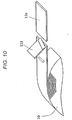
- FIG. 12 is a diagram illustrating a technique for forming the convex end 141 on a stator core insertion side end 19a.
- a halfway product of the slot liner 19 which is cut into the constant length after it is formed into a shape of the rectangular tube shaped slot liner by roll forming is grasped by a slot liner holder 51, a plain milling cutter 52 is obliquely moved on a stator core insertion side end 19a whose end projects by a predetermined length, thereby forming an inclined portion on one side of the slot liner end.
- a technique shown in FIG. 13 can be employed.
- a halfway product of a rectangular tube shaped slot liner 19 is inserted into a slot liner holder 53 having a circular inner surface having a circumference which is slightly shorter than a circumferential length of the slot liner and according to this, the halfway product spreads into a cylindrical shape and is fixed.
- a rotary bar 54 is applied to the segment coil insertion side end 19b of the slot liner 19 which spreads into the cylindrical shape projecting from the end surface of the holder 53 by a predetermined length. According to this, the segment coil insertion side end 19b is formed into the concave shape.
- slot liner having a rectangular cross section which is cut at a plane perpendicular to an extending direction of the slot liner
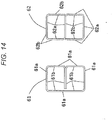
- slot liner 61 having a B-shaped traverse cross section or a slot liner 62 having an S-shaped traverse cross section shown in FIG. 14 .
- B-shaped slot liner 61 and the S-shaped slot liner 62 two spaces surrounded by rectangular shapes exist at upper and lower locations in the drawing, and the segment coils 3 are inserted into the spaces from front direction or a depth direction in the drawing.
- one surface 61a of both surfaces of the insulating paper before the slot liner is formed into the B-shape appears on a B-shaped outer periphery when the slot liner is formed into the B-shape, and the one surface 61a comes into contact with the slot 4.
- the other surface 61b of the both surfaces of the insulating paper before the slot liner is formed into the B-shape appears on a B-shaped inner periphery when the slot liner is formed into the B-shape, and the other surface 61b comes into contact with the segment coils 3.
- one surface 62a of both surfaces of the insulating paper before the slot liner is formed into the S-shape appears on an inner surface surrounding upper one of two spaces surrounded by a rectangular shape when the slot liner is formed into the S-shape, and also appears on an outer surface surrounding a lower space.
- the other surface 62b of both surfaces of the insulating paper before the slot liner is formed into the S-shape appears on an outer surface surrounding upper one of the two spaces surrounded by the rectangular shape when the slot liner is formed into the S-shape, and also appears on the inner surface surrounding the lower space.
- FIGS. 15(a) to 15(f) are sectional views (vertical sectional views) which are cut at a plane parallel to the extending direction of the slot liner, and these drawings show vicinity of a segment coil insertion side end.
- the inclined surface 142a may partially be provided on an inner peripheral side of a slot liner 151 after the inclined surface 142a is formed into a rectangular shape.
- the inclined surface 142a may partially be provided on an inner peripheral side of a slot liner 152 after it is formed into a rectangular shape, and an inclined surface 142b having an inclination angle which is different from that of the inclined surface 142a may be provided from a left end of the inclined surface 142a in the drawing. In this manner, multiple inclined surfaces having different inclination angles may be provided.
- a surface 142c formed by chamfering an outer peripheral end of a slot liner 153 may be provided as shown in FIG. 15 (d) .
- inclined surfaces 142d and 142e of slot liners 154 and 155 may be curved surfaces as shown in FIGS. 15(e) and 15(f) .
- the concave end 142 may be formed by appropriately combining the inclined surfaces 142a to 142e.
- the second gradient angles 134 of the inclined surfaces 142a to 142e are defined as shown in FIGS. 15(a) to 15(f) . That is, the second gradient angle 134 is defined by an angle formed between an inner surface of the slot liner and a tangent of each inclined surface at an intersection between the inclined surfaces 142a, 142d and 142e and the inner surface of the slot liner.
- a shape of an outer periphery in the vicinity of the concave end 142 is not limited to the shape of the surface 142c shown in FIG. 15(d) , and the shape of the outer periphery may be composed of multiple flat surfaces having different inclination angles or may be composed of a curved surface.
- the present invention is not limited to this, and a sheet-shaped insulating member made of other material may appropriately be used.
- the above-described Examples and Comparative Example may be combined with each other.
- a rotating machine of the invention includes rotating machines of various kinds of structure. That is, the rotating machine including: a core provided with a slot which is in communication with the core in an axial direction thereof; a winding provided in the slot; and an insulating member provided between the slot and the winding; where in the insulating-member, a first inclined surface provided on an insertion side into the slot and/or a second inclined surface provided on an insertion side of the winding is provided on an end of the core in its axial direction.
Landscapes
- Engineering & Computer Science (AREA)
- Power Engineering (AREA)
- Insulation, Fastening Of Motor, Generator Windings (AREA)
- Manufacture Of Motors, Generators (AREA)
Applications Claiming Priority (2)
| Application Number | Priority Date | Filing Date | Title |
|---|---|---|---|
| JP2013165181A JP6049566B2 (ja) | 2013-08-08 | 2013-08-08 | 回転電機 |
| PCT/JP2014/064047 WO2015019685A1 (ja) | 2013-08-08 | 2014-05-28 | 回転電機 |
Publications (3)
| Publication Number | Publication Date |
|---|---|
| EP3032710A1 EP3032710A1 (en) | 2016-06-15 |
| EP3032710A4 EP3032710A4 (en) | 2017-05-10 |
| EP3032710B1 true EP3032710B1 (en) | 2018-09-26 |
Family
ID=52461032
Family Applications (1)
| Application Number | Title | Priority Date | Filing Date |
|---|---|---|---|
| EP14835348.5A Active EP3032710B1 (en) | 2013-08-08 | 2014-05-28 | Rotating electrical machine |
Country Status (5)
| Country | Link |
|---|---|
| US (1) | US10230281B2 (enExample) |
| EP (1) | EP3032710B1 (enExample) |
| JP (1) | JP6049566B2 (enExample) |
| CN (1) | CN105453388B (enExample) |
| WO (1) | WO2015019685A1 (enExample) |
Families Citing this family (15)
| Publication number | Priority date | Publication date | Assignee | Title |
|---|---|---|---|---|
| WO2017047247A1 (ja) * | 2015-09-17 | 2017-03-23 | 日立オートモティブシステムズ株式会社 | 回転電機 |
| DE102016207532A1 (de) | 2016-05-02 | 2017-11-02 | Aumann Gmbh | Verfahren und Vorrichtung zum Herstellen eines Isolationselements |
| US11183898B2 (en) * | 2016-07-08 | 2021-11-23 | Hitachi Industrial Equipment Systems Co., Ltd. | Rotary electric machine and manufacturing method for rotary electric machine |
| JP6389501B2 (ja) * | 2016-11-30 | 2018-09-12 | 公明 岩谷 | 回転機用コイル及び回転機 |
| JP7218180B2 (ja) * | 2017-01-16 | 2023-02-06 | 本田技研工業株式会社 | 絶縁部材、回転電機のステータおよび回転電機 |
| DE102017208566A1 (de) * | 2017-05-19 | 2018-11-22 | Mahle International Gmbh | Elektrische Maschine, insbesondere für ein Fahrzeug |
| DE102017208550A1 (de) * | 2017-05-19 | 2018-11-22 | Mahle International Gmbh | Elektrische Maschine, insbesondere für ein Fahrzeug |
| CN111837317B (zh) * | 2018-03-23 | 2023-05-30 | 株式会社爱信 | 定子的制造方法、定子的制造装置以及定子 |
| FR3082372B1 (fr) * | 2018-06-07 | 2022-06-03 | Leroy Somer Moteurs | Stator de machine electrique tournant |
| CN108631525B (zh) * | 2018-06-29 | 2023-09-26 | 江苏本格自动化科技有限公司 | 一种快速成型的压纸料库 |
| JP7181781B2 (ja) * | 2018-12-10 | 2022-12-01 | 株式会社Soken | 回転電機、電力変換装置及び回転電機の製造方法 |
| CN114450870A (zh) * | 2019-09-23 | 2022-05-06 | 卡诺科技公司 | 包括具有矩形横截面的线圈元件的分数槽电动马达 |
| CN111633127B (zh) * | 2020-06-08 | 2022-04-05 | 哈尔滨电气动力装备有限公司 | 湿绕组电机转子槽衬弯形工具 |
| EP3958443A1 (en) * | 2020-08-20 | 2022-02-23 | ATOP S.p.A. | Stator, apparatus and method for preparing a pre-shaped insulator |
| JP7195358B2 (ja) * | 2021-03-17 | 2022-12-23 | 本田技研工業株式会社 | ステータ及びステータの製造方法 |
Family Cites Families (19)
| Publication number | Priority date | Publication date | Assignee | Title |
|---|---|---|---|---|
| JPS471988U (enExample) * | 1971-01-21 | 1972-08-22 | ||
| US4247978A (en) * | 1979-01-04 | 1981-02-03 | General Electric Company | Methods of making slot liners and stator assemblies including same |
| JPS6086476U (ja) * | 1983-11-17 | 1985-06-14 | 旭大隈産業株式会社 | 塗装装置の警告装置 |
| JPS6254551U (enExample) * | 1985-05-31 | 1987-04-04 | ||
| JPH0521954Y2 (enExample) * | 1986-08-20 | 1993-06-04 | ||
| DE3721423A1 (de) * | 1987-06-29 | 1989-01-19 | Gaemmerler Hagen | Schneidvorrichtung fuer mindestens zweilagige flaechengebilde, insbesondere papierprodukte |
| EP0961386B1 (en) | 1998-05-25 | 2003-01-02 | Denso Corporation | Stator of ac generator for vehicle |
| JP3508755B2 (ja) * | 1998-05-25 | 2004-03-22 | 株式会社デンソー | 車両用交流発電機の製造方法 |
| JP3609649B2 (ja) * | 1999-06-29 | 2005-01-12 | 三洋電機株式会社 | ブラシレスdcモータ及びこのモータを用いた冷媒圧縮機 |
| JP2003070201A (ja) * | 2001-08-23 | 2003-03-07 | Toyota Motor Corp | 回転電機のステータおよびその製造方法 |
| JP2003088028A (ja) * | 2001-09-11 | 2003-03-20 | Moric Co Ltd | 回転電気機器の電機子のインシュレータ |
| KR101070997B1 (ko) * | 2009-11-03 | 2011-10-06 | 뉴모텍(주) | 압축기용 모터의 스테이터 |
| JP5482121B2 (ja) * | 2009-11-10 | 2014-04-23 | 株式会社富士通ゼネラル | 回転電機の固定子 |
| US8558427B2 (en) * | 2011-01-31 | 2013-10-15 | GM Global Technology Operations LLC | Insulation assembly for electric machine |
| JP5700667B2 (ja) | 2011-06-27 | 2015-04-15 | アスモ株式会社 | ステータの製造方法、ステータ及びモータ |
| JP2013021896A (ja) * | 2011-07-14 | 2013-01-31 | Hitachi Automotive Systems Ltd | 回転電機及び回転電機の固定子コイルの製造方法 |
| JP2013143819A (ja) | 2012-01-10 | 2013-07-22 | Toyota Motor Corp | ステータの製造方法及びステータ |
| CN104782028B (zh) * | 2012-11-14 | 2017-04-19 | 三菱电机株式会社 | 旋转电机的定子和旋转电机 |
| CN103618395A (zh) | 2013-09-13 | 2014-03-05 | 合肥凯邦电机有限公司 | 电机定子槽口绝缘片 |
-
2013
- 2013-08-08 JP JP2013165181A patent/JP6049566B2/ja active Active
-
2014
- 2014-05-28 US US14/910,447 patent/US10230281B2/en active Active
- 2014-05-28 WO PCT/JP2014/064047 patent/WO2015019685A1/ja not_active Ceased
- 2014-05-28 CN CN201480043911.0A patent/CN105453388B/zh active Active
- 2014-05-28 EP EP14835348.5A patent/EP3032710B1/en active Active
Non-Patent Citations (1)
| Title |
|---|
| None * |
Also Published As
| Publication number | Publication date |
|---|---|
| US20160181882A1 (en) | 2016-06-23 |
| CN105453388B (zh) | 2019-05-03 |
| CN105453388A (zh) | 2016-03-30 |
| US10230281B2 (en) | 2019-03-12 |
| WO2015019685A1 (ja) | 2015-02-12 |
| JP2015035876A (ja) | 2015-02-19 |
| EP3032710A4 (en) | 2017-05-10 |
| JP6049566B2 (ja) | 2016-12-21 |
| EP3032710A1 (en) | 2016-06-15 |
Similar Documents
| Publication | Publication Date | Title |
|---|---|---|
| EP3032710B1 (en) | Rotating electrical machine | |
| EP3238847B1 (en) | Punch processing method for laminated iron core and method for manufacturing laminated iron core | |
| CN108233575B (zh) | 旋转电机 | |
| JP6495092B2 (ja) | 分割型積層鉄心及びその製造方法 | |
| KR101501862B1 (ko) | 회전 전기 기기용 나선 코어의 제조 방법 및 회전 전기 기기용 나선 코어의 제조 장치 | |
| JP3656733B2 (ja) | 車両用回転電機の固定子、およびその製造方法 | |
| US10594182B2 (en) | Stator manufacturing method and stator | |
| US9197107B2 (en) | Stator, method for manufacturing stator, and flat conductor for winding | |
| US20160254718A1 (en) | Segment conductors, stator, rotating electrical machine, and vehicle and method of manufacturing the segment conductors | |
| CN105703565A (zh) | 层压体及其制造方法以及叠片铁芯的制造方法 | |
| EP3806298B1 (en) | Method and device for manufacturing electric apparatus coil | |
| JP2006014530A (ja) | コイルとその製造方法 | |
| CN114649913A (zh) | 轴向磁通电动机的叠片定子和制造叠片定子的方法 | |
| JP5267114B2 (ja) | 回転電機用のコア絶縁部材及び回転電機の絶縁構造 | |
| JP5144238B2 (ja) | 積層鉄心の製造方法および帯状鉄心片 | |
| JP2012217279A (ja) | 回転電機用ステータコア、回転電機、および、回転電機用ステータコアの製造方法 | |
| EP4604365A1 (en) | Rotating machine and series coil group | |
| JP7025224B2 (ja) | 回転電機のステータ | |
| CN102801241A (zh) | 电机用定子绝缘装置 | |
| JP2003189558A (ja) | 回転電機の固定子製造方法 | |
| JP2020124057A (ja) | 回転電機のインシュレータ | |
| JP6697787B1 (ja) | 導体線の絶縁被膜切除装置および絶縁被膜切除方法 | |
| JP2006157993A (ja) | セグメント式ステータ及びその製造方法 | |
| JP2019103174A (ja) | 回転電機のステータコイル | |
| US20110234361A1 (en) | Pencil core and method of manufacturing the improved pencil core |
Legal Events
| Date | Code | Title | Description |
|---|---|---|---|
| PUAI | Public reference made under article 153(3) epc to a published international application that has entered the european phase |
Free format text: ORIGINAL CODE: 0009012 |
|
| 17P | Request for examination filed |
Effective date: 20160308 |
|
| AK | Designated contracting states |
Kind code of ref document: A1 Designated state(s): AL AT BE BG CH CY CZ DE DK EE ES FI FR GB GR HR HU IE IS IT LI LT LU LV MC MK MT NL NO PL PT RO RS SE SI SK SM TR |
|
| AX | Request for extension of the european patent |
Extension state: BA ME |
|
| DAX | Request for extension of the european patent (deleted) | ||
| A4 | Supplementary search report drawn up and despatched |
Effective date: 20170412 |
|
| RIC1 | Information provided on ipc code assigned before grant |
Ipc: H02K 3/34 20060101AFI20170406BHEP |
|
| GRAP | Despatch of communication of intention to grant a patent |
Free format text: ORIGINAL CODE: EPIDOSNIGR1 |
|
| STAA | Information on the status of an ep patent application or granted ep patent |
Free format text: STATUS: GRANT OF PATENT IS INTENDED |
|
| INTG | Intention to grant announced |
Effective date: 20180524 |
|
| GRAS | Grant fee paid |
Free format text: ORIGINAL CODE: EPIDOSNIGR3 |
|
| GRAA | (expected) grant |
Free format text: ORIGINAL CODE: 0009210 |
|
| STAA | Information on the status of an ep patent application or granted ep patent |
Free format text: STATUS: THE PATENT HAS BEEN GRANTED |
|
| AK | Designated contracting states |
Kind code of ref document: B1 Designated state(s): AL AT BE BG CH CY CZ DE DK EE ES FI FR GB GR HR HU IE IS IT LI LT LU LV MC MK MT NL NO PL PT RO RS SE SI SK SM TR |
|
| REG | Reference to a national code |
Ref country code: GB Ref legal event code: FG4D |
|
| RIN1 | Information on inventor provided before grant (corrected) |
Inventor name: HAGIWARA SHUYA Inventor name: IWAKI GENZO |
|
| REG | Reference to a national code |
Ref country code: CH Ref legal event code: EP |
|
| REG | Reference to a national code |
Ref country code: AT Ref legal event code: REF Ref document number: 1047179 Country of ref document: AT Kind code of ref document: T Effective date: 20181015 |
|
| REG | Reference to a national code |
Ref country code: IE Ref legal event code: FG4D |
|
| REG | Reference to a national code |
Ref country code: DE Ref legal event code: R096 Ref document number: 602014033143 Country of ref document: DE |
|
| REG | Reference to a national code |
Ref country code: NL Ref legal event code: MP Effective date: 20180926 |
|
| PG25 | Lapsed in a contracting state [announced via postgrant information from national office to epo] |
Ref country code: FI Free format text: LAPSE BECAUSE OF FAILURE TO SUBMIT A TRANSLATION OF THE DESCRIPTION OR TO PAY THE FEE WITHIN THE PRESCRIBED TIME-LIMIT Effective date: 20180926 Ref country code: LT Free format text: LAPSE BECAUSE OF FAILURE TO SUBMIT A TRANSLATION OF THE DESCRIPTION OR TO PAY THE FEE WITHIN THE PRESCRIBED TIME-LIMIT Effective date: 20180926 Ref country code: GR Free format text: LAPSE BECAUSE OF FAILURE TO SUBMIT A TRANSLATION OF THE DESCRIPTION OR TO PAY THE FEE WITHIN THE PRESCRIBED TIME-LIMIT Effective date: 20181227 Ref country code: NO Free format text: LAPSE BECAUSE OF FAILURE TO SUBMIT A TRANSLATION OF THE DESCRIPTION OR TO PAY THE FEE WITHIN THE PRESCRIBED TIME-LIMIT Effective date: 20181226 Ref country code: BG Free format text: LAPSE BECAUSE OF FAILURE TO SUBMIT A TRANSLATION OF THE DESCRIPTION OR TO PAY THE FEE WITHIN THE PRESCRIBED TIME-LIMIT Effective date: 20181226 Ref country code: RS Free format text: LAPSE BECAUSE OF FAILURE TO SUBMIT A TRANSLATION OF THE DESCRIPTION OR TO PAY THE FEE WITHIN THE PRESCRIBED TIME-LIMIT Effective date: 20180926 Ref country code: SE Free format text: LAPSE BECAUSE OF FAILURE TO SUBMIT A TRANSLATION OF THE DESCRIPTION OR TO PAY THE FEE WITHIN THE PRESCRIBED TIME-LIMIT Effective date: 20180926 |
|
| REG | Reference to a national code |
Ref country code: LT Ref legal event code: MG4D |
|
| PG25 | Lapsed in a contracting state [announced via postgrant information from national office to epo] |
Ref country code: LV Free format text: LAPSE BECAUSE OF FAILURE TO SUBMIT A TRANSLATION OF THE DESCRIPTION OR TO PAY THE FEE WITHIN THE PRESCRIBED TIME-LIMIT Effective date: 20180926 Ref country code: AL Free format text: LAPSE BECAUSE OF FAILURE TO SUBMIT A TRANSLATION OF THE DESCRIPTION OR TO PAY THE FEE WITHIN THE PRESCRIBED TIME-LIMIT Effective date: 20180926 Ref country code: HR Free format text: LAPSE BECAUSE OF FAILURE TO SUBMIT A TRANSLATION OF THE DESCRIPTION OR TO PAY THE FEE WITHIN THE PRESCRIBED TIME-LIMIT Effective date: 20180926 |
|
| REG | Reference to a national code |
Ref country code: AT Ref legal event code: MK05 Ref document number: 1047179 Country of ref document: AT Kind code of ref document: T Effective date: 20180926 |
|
| PG25 | Lapsed in a contracting state [announced via postgrant information from national office to epo] |
Ref country code: ES Free format text: LAPSE BECAUSE OF FAILURE TO SUBMIT A TRANSLATION OF THE DESCRIPTION OR TO PAY THE FEE WITHIN THE PRESCRIBED TIME-LIMIT Effective date: 20180926 Ref country code: IS Free format text: LAPSE BECAUSE OF FAILURE TO SUBMIT A TRANSLATION OF THE DESCRIPTION OR TO PAY THE FEE WITHIN THE PRESCRIBED TIME-LIMIT Effective date: 20190126 Ref country code: EE Free format text: LAPSE BECAUSE OF FAILURE TO SUBMIT A TRANSLATION OF THE DESCRIPTION OR TO PAY THE FEE WITHIN THE PRESCRIBED TIME-LIMIT Effective date: 20180926 Ref country code: PL Free format text: LAPSE BECAUSE OF FAILURE TO SUBMIT A TRANSLATION OF THE DESCRIPTION OR TO PAY THE FEE WITHIN THE PRESCRIBED TIME-LIMIT Effective date: 20180926 Ref country code: AT Free format text: LAPSE BECAUSE OF FAILURE TO SUBMIT A TRANSLATION OF THE DESCRIPTION OR TO PAY THE FEE WITHIN THE PRESCRIBED TIME-LIMIT Effective date: 20180926 Ref country code: IT Free format text: LAPSE BECAUSE OF FAILURE TO SUBMIT A TRANSLATION OF THE DESCRIPTION OR TO PAY THE FEE WITHIN THE PRESCRIBED TIME-LIMIT Effective date: 20180926 Ref country code: NL Free format text: LAPSE BECAUSE OF FAILURE TO SUBMIT A TRANSLATION OF THE DESCRIPTION OR TO PAY THE FEE WITHIN THE PRESCRIBED TIME-LIMIT Effective date: 20180926 Ref country code: CZ Free format text: LAPSE BECAUSE OF FAILURE TO SUBMIT A TRANSLATION OF THE DESCRIPTION OR TO PAY THE FEE WITHIN THE PRESCRIBED TIME-LIMIT Effective date: 20180926 Ref country code: RO Free format text: LAPSE BECAUSE OF FAILURE TO SUBMIT A TRANSLATION OF THE DESCRIPTION OR TO PAY THE FEE WITHIN THE PRESCRIBED TIME-LIMIT Effective date: 20180926 |
|
| PG25 | Lapsed in a contracting state [announced via postgrant information from national office to epo] |
Ref country code: SM Free format text: LAPSE BECAUSE OF FAILURE TO SUBMIT A TRANSLATION OF THE DESCRIPTION OR TO PAY THE FEE WITHIN THE PRESCRIBED TIME-LIMIT Effective date: 20180926 Ref country code: PT Free format text: LAPSE BECAUSE OF FAILURE TO SUBMIT A TRANSLATION OF THE DESCRIPTION OR TO PAY THE FEE WITHIN THE PRESCRIBED TIME-LIMIT Effective date: 20190126 Ref country code: SK Free format text: LAPSE BECAUSE OF FAILURE TO SUBMIT A TRANSLATION OF THE DESCRIPTION OR TO PAY THE FEE WITHIN THE PRESCRIBED TIME-LIMIT Effective date: 20180926 |
|
| REG | Reference to a national code |
Ref country code: DE Ref legal event code: R097 Ref document number: 602014033143 Country of ref document: DE |
|
| PG25 | Lapsed in a contracting state [announced via postgrant information from national office to epo] |
Ref country code: DK Free format text: LAPSE BECAUSE OF FAILURE TO SUBMIT A TRANSLATION OF THE DESCRIPTION OR TO PAY THE FEE WITHIN THE PRESCRIBED TIME-LIMIT Effective date: 20180926 |
|
| PLBE | No opposition filed within time limit |
Free format text: ORIGINAL CODE: 0009261 |
|
| STAA | Information on the status of an ep patent application or granted ep patent |
Free format text: STATUS: NO OPPOSITION FILED WITHIN TIME LIMIT |
|
| 26N | No opposition filed |
Effective date: 20190627 |
|
| PG25 | Lapsed in a contracting state [announced via postgrant information from national office to epo] |
Ref country code: SI Free format text: LAPSE BECAUSE OF FAILURE TO SUBMIT A TRANSLATION OF THE DESCRIPTION OR TO PAY THE FEE WITHIN THE PRESCRIBED TIME-LIMIT Effective date: 20180926 |
|
| REG | Reference to a national code |
Ref country code: CH Ref legal event code: PL |
|
| GBPC | Gb: european patent ceased through non-payment of renewal fee |
Effective date: 20190528 |
|
| PG25 | Lapsed in a contracting state [announced via postgrant information from national office to epo] |
Ref country code: MC Free format text: LAPSE BECAUSE OF FAILURE TO SUBMIT A TRANSLATION OF THE DESCRIPTION OR TO PAY THE FEE WITHIN THE PRESCRIBED TIME-LIMIT Effective date: 20180926 Ref country code: CH Free format text: LAPSE BECAUSE OF NON-PAYMENT OF DUE FEES Effective date: 20190531 Ref country code: LI Free format text: LAPSE BECAUSE OF NON-PAYMENT OF DUE FEES Effective date: 20190531 |
|
| REG | Reference to a national code |
Ref country code: BE Ref legal event code: MM Effective date: 20190531 |
|
| PG25 | Lapsed in a contracting state [announced via postgrant information from national office to epo] |
Ref country code: LU Free format text: LAPSE BECAUSE OF NON-PAYMENT OF DUE FEES Effective date: 20190528 |
|
| PG25 | Lapsed in a contracting state [announced via postgrant information from national office to epo] |
Ref country code: TR Free format text: LAPSE BECAUSE OF FAILURE TO SUBMIT A TRANSLATION OF THE DESCRIPTION OR TO PAY THE FEE WITHIN THE PRESCRIBED TIME-LIMIT Effective date: 20180926 |
|
| PG25 | Lapsed in a contracting state [announced via postgrant information from national office to epo] |
Ref country code: GB Free format text: LAPSE BECAUSE OF NON-PAYMENT OF DUE FEES Effective date: 20190528 Ref country code: IE Free format text: LAPSE BECAUSE OF NON-PAYMENT OF DUE FEES Effective date: 20190528 |
|
| PG25 | Lapsed in a contracting state [announced via postgrant information from national office to epo] |
Ref country code: BE Free format text: LAPSE BECAUSE OF NON-PAYMENT OF DUE FEES Effective date: 20190531 |
|
| PG25 | Lapsed in a contracting state [announced via postgrant information from national office to epo] |
Ref country code: FR Free format text: LAPSE BECAUSE OF NON-PAYMENT OF DUE FEES Effective date: 20190531 |
|
| REG | Reference to a national code |
Ref country code: DE Ref legal event code: R082 Ref document number: 602014033143 Country of ref document: DE Representative=s name: MERH-IP MATIAS ERNY REICHL HOFFMANN PATENTANWA, DE Ref country code: DE Ref legal event code: R081 Ref document number: 602014033143 Country of ref document: DE Owner name: HITACHI ASTEMO, LTD., HITACHINAKA-SHI, JP Free format text: FORMER OWNER: HITACHI AUTOMOTIVE SYSTEMS, LTD., HITACHINAKA-SHI, IBARAKI, JP |
|
| PG25 | Lapsed in a contracting state [announced via postgrant information from national office to epo] |
Ref country code: CY Free format text: LAPSE BECAUSE OF FAILURE TO SUBMIT A TRANSLATION OF THE DESCRIPTION OR TO PAY THE FEE WITHIN THE PRESCRIBED TIME-LIMIT Effective date: 20180926 |
|
| PG25 | Lapsed in a contracting state [announced via postgrant information from national office to epo] |
Ref country code: HU Free format text: LAPSE BECAUSE OF FAILURE TO SUBMIT A TRANSLATION OF THE DESCRIPTION OR TO PAY THE FEE WITHIN THE PRESCRIBED TIME-LIMIT; INVALID AB INITIO Effective date: 20140528 Ref country code: MT Free format text: LAPSE BECAUSE OF FAILURE TO SUBMIT A TRANSLATION OF THE DESCRIPTION OR TO PAY THE FEE WITHIN THE PRESCRIBED TIME-LIMIT Effective date: 20180926 |
|
| PG25 | Lapsed in a contracting state [announced via postgrant information from national office to epo] |
Ref country code: MK Free format text: LAPSE BECAUSE OF FAILURE TO SUBMIT A TRANSLATION OF THE DESCRIPTION OR TO PAY THE FEE WITHIN THE PRESCRIBED TIME-LIMIT Effective date: 20180926 |
|
| PGFP | Annual fee paid to national office [announced via postgrant information from national office to epo] |
Ref country code: DE Payment date: 20250402 Year of fee payment: 12 |