EP3031128B1 - A method of and apparatus for detecting coil alignment error in wireless inductive power transmission - Google Patents
A method of and apparatus for detecting coil alignment error in wireless inductive power transmission Download PDFInfo
- Publication number
- EP3031128B1 EP3031128B1 EP14834116.7A EP14834116A EP3031128B1 EP 3031128 B1 EP3031128 B1 EP 3031128B1 EP 14834116 A EP14834116 A EP 14834116A EP 3031128 B1 EP3031128 B1 EP 3031128B1
- Authority
- EP
- European Patent Office
- Prior art keywords
- coil
- inductive coil
- eddy current
- secondary inductive
- primary
- Prior art date
- Legal status (The legal status is an assumption and is not a legal conclusion. Google has not performed a legal analysis and makes no representation as to the accuracy of the status listed.)
- Active
Links
Images


Classifications
-
- H—ELECTRICITY
- H02—GENERATION; CONVERSION OR DISTRIBUTION OF ELECTRIC POWER
- H02J—CIRCUIT ARRANGEMENTS OR SYSTEMS FOR SUPPLYING OR DISTRIBUTING ELECTRIC POWER; SYSTEMS FOR STORING ELECTRIC ENERGY
- H02J50/00—Circuit arrangements or systems for wireless supply or distribution of electric power
- H02J50/10—Circuit arrangements or systems for wireless supply or distribution of electric power using inductive coupling
- H02J50/12—Circuit arrangements or systems for wireless supply or distribution of electric power using inductive coupling of the resonant type
-
- H—ELECTRICITY
- H02—GENERATION; CONVERSION OR DISTRIBUTION OF ELECTRIC POWER
- H02J—CIRCUIT ARRANGEMENTS OR SYSTEMS FOR SUPPLYING OR DISTRIBUTING ELECTRIC POWER; SYSTEMS FOR STORING ELECTRIC ENERGY
- H02J50/00—Circuit arrangements or systems for wireless supply or distribution of electric power
- H02J50/90—Circuit arrangements or systems for wireless supply or distribution of electric power involving detection or optimisation of position, e.g. alignment
-
- H—ELECTRICITY
- H02—GENERATION; CONVERSION OR DISTRIBUTION OF ELECTRIC POWER
- H02J—CIRCUIT ARRANGEMENTS OR SYSTEMS FOR SUPPLYING OR DISTRIBUTING ELECTRIC POWER; SYSTEMS FOR STORING ELECTRIC ENERGY
- H02J50/00—Circuit arrangements or systems for wireless supply or distribution of electric power
- H02J50/70—Circuit arrangements or systems for wireless supply or distribution of electric power involving the reduction of electric, magnetic or electromagnetic leakage fields
Definitions
- This patent application pertains to the transmission of electrical energy by means of resonant magnetic induction. More specifically, it describes a method of and apparatus for detecting axial misalignment of resonant inductive wireless power transfer coils and providing an indication of the magnitude and direction of the alignment error so that the alignment error can be minimized or eliminated thereby ensuring efficient wireless power transfer.
- FIG. 1 shows a conceptual representation of a conventional resonant inductive power transmission system.
- DC power supply 10 inverter 12 , and resonating network 14 cooperate to provide a source of alternating electrical energy that is applied to the primary induction coil 16 .
- Magnetic coupling between the primary induction coil 16 and a secondary induction coil 18 transfers energy to the secondary induction coil 18 , which is removed by some distance from the primary induction coil 16 .
- the primary and secondary induction coils 16 , 18 constitute a loosely coupled air core transformer.
- Resonance applied to the primary induction coil 16 increases primary side inductor current producing a corresponding increase in the magnetic flux in the secondary inductor current and, therefore, in the power transferred from the primary to the secondary.
- the secondary inductor current is processed by a resonating network 20 and is rectified by a high-power rectifier 22 for application to DC load 24 in a conventional manner.
- Efficient resonant inductive wireless power transfer requires that a significant portion of the magnetic flux lines emitted by the sending coil travel through the area contained by the perimeter of the receiving coil so as to maximize magnetic coupling.
- Axial coil misalignment significantly reduces coil-to-coil magnetic coupling and therefor detracts from efficient power transfer.
- axial coil misalignment alters coil inductance from expected design values leading to loss of resonance and additional power transfer inefficiencies.
- Coil axial alignment errors are encountered routinely and present a critical problem for manufacturers of electric and electric-hybrid vehicles that require a wireless source of external source of power. It is desired to develop a system for charging vehicles that identifies the magnitude and direction of coil alignment error and provides steering information to a human driver or non-human apparatus in order that the vehicle may be positioned with minimal coil alignment error.
- the present invention addresses these needs in the art.
- US 2013/0049484 A1 describes an inductive power transfer system operable in a plurality of modes comprising an inductive power transmitter capable of providing power to the inductive power receiver over an extended region.
- the system may be switchable between the various modes by means of a mode selector operable to activate various features as required, such as: an alignment mechanism a resonance tuner, an auxiliary coil arrangement or a resonance seeking arrangement.
- An axial alignment error detection apparatus and associated method that meets the aforementioned needs in the art includes several (e.g. four) arc segment eddy current coils superimposed on the primary induction coil of a conventional resonant inductance wireless power transmission system.
- the linear sections of the eddy coil perimeters align with the forward-reverse and left-right axes of the primary induction coil.
- Each arc segment eddy current coil connects to a bridge rectifier, and a switching element such as a field effect transistor.
- the switching elements are activated singularly or in unison by a sequencer.
- the secondary induction coil connects to a resonating network, a high power rectifier, and a DC load as in conventional resonant induction wireless power transmission systems.
- the axial alignment error detection system of the invention adds a voltage detector including a low power rectifier, an Analog-to-Digital Converter (ADC), a data link, a microcontroller, and a vehicle operator interface to the conventional vehicle side resonant induction wireless power transmission system.
- ADC Analog-to-Digital Converter
- a direct current power supply is generally driven by commercial alternating line current.
- the resulting direct current powers an inverter stage that generates a square, rectangular or sinusoidal waveform at the resonant frequency of the primary and secondary induction coils. If the arc segment eddy current coil switching elements are all commanded into the off state by the sequencer, the eddy current coils are effectively open circuited, no current flows in the arc segment eddy current coils, and the operation of the conventional art resonant induction wireless power transmission apparatus is not affected nor altered to any significant extent.
- eddy currents flow in the corresponding eddy current coils and, in accordance with Lentz's law, the eddy currents reduce the combined magnetic flux enclosed within the eddy coil perimeter, thereby reducing the net magnitude of the primary coil flux in that quadrant.
- the sequencer communicates to the vehicle side portion of the alignment apparatus which eddy current coils are active during alignment error determination by means of a short ranged data link.
- Bridge rectifiers allow conventional unidirectional semiconductor switching elements, such as field effect or bipolar transistors, to control the alternating current present in an activated arc segment eddy current coil.
- a unidirectional, alternating current semiconductor switch comprising two field effect transistors connected source-to-source, and gate-to-gate can be used for eddy current coil control elements in place of the single transistor, bridge rectifier combination.
- a voltage detector including the low power rectifier, converted to digital representation by the analog-to-digital converter, and processed by the microcontroller.
- An active eddy current coil has the effect of reducing the magnetic flux intercepted by the secondary induction coil, thereby reducing the voltage generated by the low power rectifier.
- Alignment may be detected by activating the eddy current coils sequentially. If the primary and secondary induction coils are axially aligned, the magnetic flux field disturbances induced by the individual eddy coils will have equal magnitude and there will be no variations of the secondary induction coil detected voltage during the eddy current coil switching sequence. If, however, the primary and secondary induction coils are misaligned, there will be variations of the secondary induction coil detected voltage during the eddy current coil switching sequence. The magnetic flux reduction effect is largest for those eddy current coils with the greatest overlap of the secondary coils and the magnitude of the detected variation indicates the extent of the overlap. Large overlaps create large variation and small overlaps generate proportionally smaller variation.
- Correspondence between the eddy current coil switch sequence and the largest magnetic flux variation indicates the error vector direction, while the magnitude of the magnetic flux variations indicates the error vector magnitude. Identification of which eddy current coil is active is provided by the data link. Thus, the alignment error vector components, offset direction and magnitude may be easily determined and communicated to the vehicle operator.
- the induction coil alignment apparatus is also used in non-vehicle applications such as portable consumer electronic device chargers, such as those ( e . g ., PowerMatTM) used to charge toothbrushes, cellular telephones, and other devices.
- portable consumer electronic device chargers such as those ( e . g ., PowerMatTM) used to charge toothbrushes, cellular telephones, and other devices.
- An unaltered, un-supplemented wireless power transfer apparatus can give a primitive indication of coil alignment error as, ignoring resonance de-tuning effects, transferred power is maximized when alignment error is zero. Consequently, less than expected power transfer implies some measure of misalignment. Because resonant inductive wireless power transfer primary coils have axial symmetry, in the case of circular or square primary coils, or quadratic symmetry in the case of rectangular or oval primary coils, the projected flux pattern is symmetrical as well, making determination of alignment error azimuth impossible. The alignment error magnitude may be supposed but not the error direction.
- the solution to this problem in accordance with the invention is to introduce spatial asymmetries in the magnetic flux field surrounding the primary induction coil that thereby enable error azimuth determination.
- One way to do this is to add auxiliary coils superimposed upon or just outside of the perimeter of the primary induction coil 16 .
- Each auxiliary coil is driven by a generator to generate magnetic flux that can supplement or partially cancel the magnetic flux generated by the primary induction coil 16 and in this way generate the axial asymmetry needed for error vector determination.
- First is the need for auxiliary coil drive circuitry beyond that needed to drive the primary induction coil 16 .
- a second difficulty arises from the resonance generating network connected between the main power driver and the primary induction coil 16 .
- auxiliary coil drivers must monitor the primary induction coil current using it as a reference in the generation of auxiliary coil currents, an undesirable requirement that increases apparatus cost and complexity.
- Auxiliary coil current generation and control is further complicated by the presence of substantial induced voltage in the auxiliary coils as well as auxiliary coil to auxiliary coil mutual coupling which makes the drive point impedance, complex and potentially unstable.
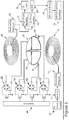
- the difficulties and complexities described above are avoided in the exemplary embodiment shown in FIG. 2 .
- the radial arc segment eddy current coils 36, 38, 40, and 42 are driven by magnetic induction; no auxiliary inverters are required and drive current phase ambiguity is entirely avoided.
- Auxiliary inverter circuits for each radial arc segment eddy current coil 36, 38, 40 , and 42 are replaced with a bridge rectifier and switching transistor 48, 50, 52 , and 54 , respectively.
- the bridge rectifiers 48, 50, 52 , and 54 allow control of bi-directional eddy currents with a single unidirectional semiconductor switch, thereby enabling the unidirectional, direct current switching device to allow or prevent the flow of induced eddy currents in the associated eddy current coil 36, 38, 40, or 42 .
- the primary induction coil 16 is operated at low power during the alignment error detection operation thereby mitigating undesired parasitic eddy currents induced into the vehicle underbody and excessive magnetic field leakage that can result during high power operation with significantly misaligned primary and secondary induction coils 16, 18 .
- a unidirectional, alternating current semiconductor switch comprising two field effect transistors connected source-to-source and gate-to-gate can be used for eddy current coil control elements in place of the single transistor, bridge rectifier combination illustrated in Figure 2 .
- eddy currents flowing in an activated eddy current coil generate a magnetic flux in opposition to the incident magnetic flux field, thereby diminishing the net magnetic flux field directly above the active eddy current coil.
- the locally diminished magnetic flux field in turn reduces the magnitude of the voltage or current induced into the secondary, vehicle side coil 18 . If the primary and secondary induction coils 16, 18 are axially aligned, all active eddy current coils 36, 38, 40 , and 42 reduce the induced secondary coil voltage or current to the same extent.
- the back-right eddy current coil will influence the secondary induction coil induced voltage or current to a greater extent than the other three eddy current coils with the degree of influence being proportional to the alignment error magnitude.
- This means the direction and the magnitude of the alignment error is readily determined by sequentially activating the eddy current coils 36, 38, 40 , and 42 using sequencer 46 and noting the secondary coil induced voltage or induced current amplitude variations that result.
- Secondary side alignment error determination requires knowledge of which eddy current coil is active at all times during the alignment error determination process, with such knowledge communicated to the secondary side microcontroller 30 by means of the data link including primary side data link 44 and secondary side data link 32 .
- sequencer 46 shown in FIG. 2 activates the arc segment eddy current coils 36, 38, 40 , and 42 in the sequence indicated in Table 1: Table 1- Exemplary Sequencer Sequence State Coils Activated 1 Front Right 2 Back-Right 3 Back-Left 4 Front-Left
- the fourth sequencer state is followed by return to the first state of the sequence and the pattern repeats.
- the secondary side microcontroller 30 measures and records the secondary coil induced voltage, E IND by means of a voltage detector such as low power rectifier 26 , which provides the measured voltage to Analog-to-Digital Converter (ADC) 28 for digitization prior to application to microcontroller 30 .
- ADC Analog-to-Digital Converter
- AE LR E IND ⁇ FL + E IND ⁇ BL ⁇ E IND ⁇ FR + E IND ⁇ BR
- Right-to-left and front-to-back alignment error magnitudes may be combined into a single alignment error vector by use of conventional vector arithmetic known to those skilled in the art.
- Any misalignment of the primary and secondary induction coils 16, 18 is communicated to the user/vehicle operator via a vehicle operator interface 34 so that the appropriate adjustments may be made by the user/vehicle operator to improve the alignment of the primary and secondary induction coils 16, 18 .
- sequencer switching patterns are possible including sequential activation of single or multiple eddy current coils 36, 38, 40 , and 42 in a clockwise or counter-clockwise pattern or simultaneous activation of several or all eddy current coils 36, 38, 40 , and 42 with each coil driven by a unique clock with error magnitude and direction determined by means of mathematical processing of the resulting secondary induction coil induced voltage.
- FIG. 3 shows a second embodiment that eliminates the need for a primary side-to-secondary side data link 44, 32 .
- the sequencer 46 drives all four arc segment eddy current coils 36, 38, 40 , and 42 simultaneously with the front-left coil driven by a square wave clock at frequency f 1 , the front-right eddy coil driven at frequency f 2 , the back-right eddy current coil driven at frequency f 3 , and the back-left eddy current coil driven at frequency f 4 .
- the frequency difference between the highest and the lowest frequency should be less than an octave to avoid confusion of generated actual clock frequencies and clock frequency harmonics possibly generated by distortion.
- the four sequencer clock frequencies f 1 , f 2 , f 3 , and f 4 could be 800, 900, 1000 and 1100 Hertz.
- rectangular wave and sinusoidal waveforms may also be used at the respective frequencies f 1 -f n , where n is the number of eddy current coils.
- the microcontroller 30 examines the data time series generated by the Analog-to-Digital-Converter 28 and performs a fast Fourier transform or similar time domain to frequency domain conversion on the ADC data time series. FFT parameters are selected such that each sequencer clock tone falls uniquely into a single frequency domain bin. In this way, the FFT operation by microcontroller 30 determines the relative contributions of the quadrature eddy current coils 36, 38, 40 , and 42 . Equal sequencer clock tone amplitudes indicate zero alignment error. Unequal clock tone amplitudes indicate an alignment error and the clock tone amplitude ratios indicate the magnitude and direction of the alignment error. Microcontroller FFT computation requirements are low because high frequency resolution is not required and the number of FFT arithmetic calculations is low. A data link is not required because each eddy current coil is uniquely identified by its specific modulation frequency.
- the number of eddy current coils 36, 38, 40 , and 42 and the coil arc width may vary. For example, four overlapping "D" shaped coils each covering a 180 degree arc width segment, two coils for front-back error determination and another two coils used for left-right error determination may be used. Alternatively, three, non-overlapping eddy current coils each covering a 120 degree arc can be used. Furthermore, a large number of eddy current coils may be used each encompassing an arc width segment less than 90 degrees to improve alignment error accuracy and resolution.
- rectifier configurations other than the bridge rectifier configuration may be used for eddy current coil control.
- the rectifier-transistor eddy current control pair may be replaced with a bi-directional control device such as a relay closure, a TRAC diode, or similar device.
- the low power rectifier block 26 in FIG. 2 and FIG. 3 may be eliminated with the high power rectifier 22 used instead.
- an app or other notifying means is loaded onto the cell phone that causes the cell phone to make a sound or vibrate when properly aligned over the charging coil. This is particularly useful for vehicle applications where it is desirable to indicate alignment of the phone with the charger without the driver having to look down. Accordingly, these and other such applications are included within the scope of the following claims.
Landscapes
- Engineering & Computer Science (AREA)
- Computer Networks & Wireless Communication (AREA)
- Power Engineering (AREA)
- Charge And Discharge Circuits For Batteries Or The Like (AREA)
- Electric Propulsion And Braking For Vehicles (AREA)
- Current-Collector Devices For Electrically Propelled Vehicles (AREA)
Applications Claiming Priority (2)
| Application Number | Priority Date | Filing Date | Title |
|---|---|---|---|
| US201361862572P | 2013-08-06 | 2013-08-06 | |
| PCT/US2014/049928 WO2015021144A1 (en) | 2013-08-06 | 2014-08-06 | A method of and apparatue for detecting coil alignment error in wirelss inductive power transmission |
Publications (3)
| Publication Number | Publication Date |
|---|---|
| EP3031128A1 EP3031128A1 (en) | 2016-06-15 |
| EP3031128A4 EP3031128A4 (en) | 2017-03-15 |
| EP3031128B1 true EP3031128B1 (en) | 2018-11-21 |
Family
ID=52461904
Family Applications (1)
| Application Number | Title | Priority Date | Filing Date |
|---|---|---|---|
| EP14834116.7A Active EP3031128B1 (en) | 2013-08-06 | 2014-08-06 | A method of and apparatus for detecting coil alignment error in wireless inductive power transmission |
Country Status (10)
| Country | Link |
|---|---|
| US (1) | US10193400B2 (enExample) |
| EP (1) | EP3031128B1 (enExample) |
| JP (1) | JP6360649B2 (enExample) |
| KR (1) | KR102187905B1 (enExample) |
| CN (1) | CN105765828B (enExample) |
| CA (1) | CA2920630C (enExample) |
| ES (1) | ES2707972T3 (enExample) |
| MX (1) | MX363580B (enExample) |
| PT (1) | PT3031128T (enExample) |
| WO (1) | WO2015021144A1 (enExample) |
Families Citing this family (42)
| Publication number | Priority date | Publication date | Assignee | Title |
|---|---|---|---|---|
| US9935488B2 (en) * | 2013-12-25 | 2018-04-03 | Panasonic Intellectual Property Management Co., Ltd. | Portable terminal charging apparatus and automobile having portable terminal charging apparatus mounted therein |
| US9626258B2 (en) | 2014-03-26 | 2017-04-18 | Qualcomm Incorporated | Systems, methods, and apparatus related to wireless charging management |
| US9837862B2 (en) | 2014-10-16 | 2017-12-05 | DePuy Synthes Products, Inc. | Inductively-powered surgical instrument system |
| KR20170041389A (ko) * | 2015-10-07 | 2017-04-17 | 엘지이노텍 주식회사 | 무선 충전 디바이스 정렬 안내 방법 및 그를 위한 장치 및 시스템 |
| CN107438934B (zh) | 2015-11-05 | 2020-10-02 | Lg 电子株式会社 | 用于车辆的无线电力发射机和接收机 |
| US10124690B2 (en) | 2015-11-13 | 2018-11-13 | Nio Usa, Inc. | Electric vehicle charging device positioning and method of use |
| US10093195B2 (en) | 2015-11-13 | 2018-10-09 | Nio Usa, Inc. | Integrated vehicle charging panel system and method of use |
| US10059213B2 (en) | 2015-11-13 | 2018-08-28 | Nio Usa, Inc. | Charging devices within wheel portions |
| US10336194B2 (en) * | 2015-11-13 | 2019-07-02 | Nio Usa, Inc. | Electric vehicle charging device alignment and method of use |
| EP3353875B1 (en) * | 2015-11-19 | 2020-06-24 | Apple Inc. | Inductive power transmitter |
| US10516304B2 (en) * | 2015-12-22 | 2019-12-24 | Intel Corporation | Wireless charging coil placement for reduced field exposure |
| US10411492B2 (en) | 2015-12-23 | 2019-09-10 | Intel Corporation | Wireless power transmitter shield with capacitors |
| CN105811599A (zh) * | 2016-05-06 | 2016-07-27 | 复旦大学 | 一种基于运动跟踪的无线能量传递方法 |
| US20170365403A1 (en) * | 2016-06-16 | 2017-12-21 | Evatran Group, Inc. | Passive alignment system and method |
| GB2551372A (en) * | 2016-06-16 | 2017-12-20 | Bombardier Primove Gmbh | A secondary unit, a system for inductive power transfer and a method for operating a secondary unit and a system for inductive power transfer |
| CN106130197A (zh) * | 2016-08-31 | 2016-11-16 | 矽力杰半导体技术(杭州)有限公司 | 电能接收天线和应用其的可穿戴电子设备 |
| CN106385072B (zh) * | 2016-10-11 | 2019-12-06 | 赵莹 | 一种无线电传输系统及其应用装置 |
| EP3346581B1 (en) * | 2017-01-04 | 2023-06-14 | LG Electronics Inc. | Wireless charger for mobile terminal in vehicle |
| US11437923B2 (en) * | 2017-02-13 | 2022-09-06 | Hamilton Sundstrand Corporation—Pcss | Variable resonant power converter with tunable inductor |
| JP6503398B2 (ja) * | 2017-03-31 | 2019-04-17 | 本田技研工業株式会社 | 非接触電力伝送システム |
| CN107068372B (zh) * | 2017-06-14 | 2019-04-05 | 江西联智集成电路有限公司 | 无线充电接收器的位置调节用线圈 |
| US10391875B2 (en) | 2017-07-21 | 2019-08-27 | Witricity Corporation | Vehicle alignment for wireless charging |
| CN108390464B (zh) * | 2018-03-14 | 2020-02-14 | 南京航空航天大学 | 一种非接触电能传输装置的柔性行波激励方法 |
| CN111038295B (zh) * | 2018-10-11 | 2021-04-13 | 广州小鹏汽车科技有限公司 | 一种无线充电线圈的对准控制方法、装置和电动汽车 |
| CN109895643B (zh) * | 2019-02-26 | 2020-07-07 | 浙江大学 | 一种基于差分电感的在线式电动汽车无线充电定位系统 |
| TWM582268U (zh) * | 2019-03-28 | 2019-08-11 | 瑞格電子股份有限公司 | Ceiling fan receiving box external smart device |
| CN110070816A (zh) * | 2019-04-04 | 2019-07-30 | 深圳市华星光电技术有限公司 | 显示面板驱动电路 |
| US11380480B2 (en) | 2019-07-10 | 2022-07-05 | Lear Corporation | Strip induction coil for wireless charging of a vehicle battery |
| US11007887B2 (en) | 2019-07-11 | 2021-05-18 | Lear Corporation | Tubular induction coil for wireless charging of a vehicle battery |
| CN112421787B (zh) * | 2019-08-21 | 2023-12-19 | 北京小米移动软件有限公司 | 无线充电装置、系统、控制方法、充电设备及存储介质 |
| KR102287514B1 (ko) | 2019-09-03 | 2021-08-06 | 엘지전자 주식회사 | 무선 전력 전송 장치 및 이를 구비하는 무선 전력 시스템 |
| US11784503B2 (en) | 2021-02-22 | 2023-10-10 | Inductev Inc. | Passive arc detection and mitigation in wireless power transfer system |
| US12174269B2 (en) | 2020-03-20 | 2024-12-24 | InductEV, Inc. | Current sensing in a wireless power transfer system |
| CN111509820B (zh) * | 2020-06-12 | 2020-10-16 | 深圳赫兹创新技术有限公司 | 一种无线充电控制方法以及装置 |
| US20220021243A1 (en) * | 2020-06-15 | 2022-01-20 | The Regents Of The University Of Michigan | Segmented wireless power transfer |
| CN111835100B (zh) * | 2020-08-18 | 2025-07-04 | 亨通慧充众联科技有限公司 | 电动汽车无线充电线圈的精确位置对准系统及对准方法 |
| US11817722B2 (en) | 2021-03-11 | 2023-11-14 | Inductev Inc. | Opportunity charging of queued electric vehicles |
| US12202360B2 (en) | 2021-03-19 | 2025-01-21 | Inductev Inc. | Modular magnetic flux control |
| KR102598803B1 (ko) * | 2021-04-26 | 2023-11-06 | 한국과학기술원 | 무선전력 송수신 장치 및 무선전력 송수신 방법 |
| KR20240093599A (ko) * | 2021-11-16 | 2024-06-24 | 엘지전자 주식회사 | 무선 전력 전송 시스템에서 슬롯 생성 방법 및 장치 |
| KR20240129052A (ko) | 2022-01-03 | 2024-08-27 | 인덕트이브이 인크. | 무선 충전기로의 차량들의 선택적 안내를 위한 방법 및 장치 |
| US12145461B2 (en) | 2022-01-06 | 2024-11-19 | Ev Charging Solutions, Llc | Inductive charging station |
Family Cites Families (19)
| Publication number | Priority date | Publication date | Assignee | Title |
|---|---|---|---|---|
| US7538544B2 (en) * | 2004-04-09 | 2009-05-26 | Ksr Technologies Co. | Inductive position sensor |
| US8169185B2 (en) * | 2006-01-31 | 2012-05-01 | Mojo Mobility, Inc. | System and method for inductive charging of portable devices |
| JP4311416B2 (ja) | 2006-06-30 | 2009-08-12 | 株式会社日立製作所 | 渦電流探傷法による表面欠陥長さ評価方法 |
| US20090001941A1 (en) * | 2007-06-29 | 2009-01-01 | Microsoft Corporation | Inductive Powering Surface for Powering Portable Devices |
| US8188619B2 (en) | 2008-07-02 | 2012-05-29 | Powermat Technologies Ltd | Non resonant inductive power transmission system and method |
| JP2010206866A (ja) * | 2009-02-27 | 2010-09-16 | Panasonic Corp | 電子機器及び充電器 |
| JP2010206865A (ja) * | 2009-02-27 | 2010-09-16 | Panasonic Corp | 電子機器及び充電システム |
| US8473066B2 (en) * | 2009-07-06 | 2013-06-25 | Boston Scientific Neuromodulation Company | External charger for a medical implantable device using field sensing coils to improve coupling |
| KR101801998B1 (ko) * | 2010-04-30 | 2017-11-27 | 파워매트 테크놀로지스 엘티디. | 확장된 구역에서 유도전력 전송을 하는 시스템과 방법 |
| GB2493671B (en) * | 2010-04-30 | 2016-08-24 | Cynetic Designs Ltd | Apparatus for wirelessly detecting damage in ceramic body armour via induction |
| WO2012058466A1 (en) * | 2010-10-29 | 2012-05-03 | Qualcomm Incorporated | Wireless energy transfer via coupled parasitic resonators |
| WO2012061378A2 (en) * | 2010-11-04 | 2012-05-10 | Access Business Group International Llc | Wireless power system and method with improved alignment |
| JP5770556B2 (ja) * | 2011-07-29 | 2015-08-26 | 東光株式会社 | ワイヤレス電力伝送装置および相対位置検出方法 |
| JP2015008548A (ja) | 2011-10-28 | 2015-01-15 | パナソニック株式会社 | 非接触電力伝送装置 |
| AU2012101855A4 (en) * | 2011-12-19 | 2013-01-24 | Minelab Electronics Pty Limited | Coil arrangement |
| JP6029278B2 (ja) * | 2011-12-21 | 2016-11-24 | ソニー株式会社 | 受電装置及び非接触電力伝送システム |
| JP6315382B2 (ja) * | 2013-12-19 | 2018-04-25 | パナソニックIpマネジメント株式会社 | 無線電力伝送のための送電装置および受電装置ならびに無線電力伝送システム |
| EP3145049B1 (en) * | 2014-05-15 | 2020-02-12 | Nissan Motor Co., Ltd | Wireless power supply device |
| US11207989B2 (en) * | 2016-03-22 | 2021-12-28 | University Of Georgia Research Foundation, Inc. | Wireless charging of electric vehicles |
-
2014
- 2014-08-06 MX MX2016001585A patent/MX363580B/es unknown
- 2014-08-06 US US14/910,071 patent/US10193400B2/en active Active
- 2014-08-06 CA CA2920630A patent/CA2920630C/en active Active
- 2014-08-06 CN CN201480050370.4A patent/CN105765828B/zh active Active
- 2014-08-06 ES ES14834116T patent/ES2707972T3/es active Active
- 2014-08-06 WO PCT/US2014/049928 patent/WO2015021144A1/en not_active Ceased
- 2014-08-06 EP EP14834116.7A patent/EP3031128B1/en active Active
- 2014-08-06 PT PT14834116T patent/PT3031128T/pt unknown
- 2014-08-06 JP JP2016533395A patent/JP6360649B2/ja active Active
- 2014-08-06 KR KR1020167005696A patent/KR102187905B1/ko active Active
Non-Patent Citations (1)
| Title |
|---|
| None * |
Also Published As
| Publication number | Publication date |
|---|---|
| MX363580B (es) | 2019-03-27 |
| CN105765828A (zh) | 2016-07-13 |
| JP2016529865A (ja) | 2016-09-23 |
| PT3031128T (pt) | 2019-02-12 |
| US20160181875A1 (en) | 2016-06-23 |
| MX2016001585A (es) | 2016-08-05 |
| WO2015021144A1 (en) | 2015-02-12 |
| CA2920630A1 (en) | 2015-02-12 |
| KR20160040276A (ko) | 2016-04-12 |
| KR102187905B1 (ko) | 2020-12-07 |
| JP6360649B2 (ja) | 2018-07-18 |
| US10193400B2 (en) | 2019-01-29 |
| CN105765828B (zh) | 2018-10-19 |
| WO2015021144A8 (en) | 2015-04-02 |
| CA2920630C (en) | 2021-03-23 |
| EP3031128A1 (en) | 2016-06-15 |
| ES2707972T3 (es) | 2019-04-08 |
| EP3031128A4 (en) | 2017-03-15 |
Similar Documents
| Publication | Publication Date | Title |
|---|---|---|
| EP3031128B1 (en) | A method of and apparatus for detecting coil alignment error in wireless inductive power transmission | |
| Al Mahmud et al. | Large-area free-positioning wireless power transfer to movable receivers | |
| CN112740078B (zh) | 基于异物检测的扩展范围定位系统 | |
| US11916405B2 (en) | Wireless power transmission apparatus with multiple controllers | |
| JP2018503063A (ja) | 誘導電力送信器 | |
| CN110103739B (zh) | 弱磁场激励三线圈检测装置 | |
| JP2018533339A (ja) | 一次巻線構造および二次巻線構造の相対的位置および/または方向を判定するシステムおよび方法 | |
| Zhang et al. | A coil positioning method integrated with an orthogonal decoupled transformer for inductive power transfer systems | |
| JP5915857B2 (ja) | アンテナ | |
| EP3350899B1 (en) | Methods and apparatus utilizing multi-filar alignment assistance in wireless power transfer applications | |
| JP5559312B2 (ja) | 多負荷並列磁気回路における共有磁束を用いた電磁機器およびその動作方法 | |
| JP5930182B2 (ja) | アンテナ | |
| US20210184502A1 (en) | Wireless Power System With Reconfigurable Rectifier Circuitry | |
| Yan et al. | Magnetic coupling positioning using simultaneous power and data transfer | |
| CN111799891A (zh) | 具有可重新配置的整流器电路的无线功率系统 | |
| KR20190042211A (ko) | 무선 전력 송신 장치 | |
| JP2015195675A (ja) | 電力伝送システム | |
| JP2013157944A (ja) | アンテナ | |
| Liu et al. | Non-coherent power combining for self-tuning omnidirectional wireless power transfer | |
| Liu et al. | Research on Location Identification and Efficiency Improvement Strategies for Array-Based Wireless Charging Systems with Passive Beacon Coils | |
| Gao et al. | Research on dynamic wireless power Transfer position detection technology for electric vehicles based on SSA-SVR | |
| CN120187604A (zh) | 通过自适应频率优化道路上的电动车辆的无线功率传输的方法和系统 | |
| KR20220146959A (ko) | 무선전력 송수신 장치 및 무선전력 송수신 방법 | |
| Chen | Localization and free positioning with a cooperative multiple coil transmitter for wireless power transfer | |
| JP2013021822A (ja) | アンテナ |
Legal Events
| Date | Code | Title | Description |
|---|---|---|---|
| PUAI | Public reference made under article 153(3) epc to a published international application that has entered the european phase |
Free format text: ORIGINAL CODE: 0009012 |
|
| 17P | Request for examination filed |
Effective date: 20160304 |
|
| AK | Designated contracting states |
Kind code of ref document: A1 Designated state(s): AL AT BE BG CH CY CZ DE DK EE ES FI FR GB GR HR HU IE IS IT LI LT LU LV MC MK MT NL NO PL PT RO RS SE SI SK SM TR |
|
| AX | Request for extension of the european patent |
Extension state: BA ME |
|
| DAX | Request for extension of the european patent (deleted) | ||
| REG | Reference to a national code |
Ref country code: DE Ref legal event code: R079 Ref document number: 602014036638 Country of ref document: DE Free format text: PREVIOUS MAIN CLASS: H02J0050000000 Ipc: H02J0050900000 |
|
| A4 | Supplementary search report drawn up and despatched |
Effective date: 20170209 |
|
| RIC1 | Information provided on ipc code assigned before grant |
Ipc: H02J 7/02 20160101ALI20170203BHEP Ipc: H02J 50/90 20160101AFI20170203BHEP Ipc: H02J 50/12 20160101ALI20170203BHEP |
|
| GRAP | Despatch of communication of intention to grant a patent |
Free format text: ORIGINAL CODE: EPIDOSNIGR1 |
|
| STAA | Information on the status of an ep patent application or granted ep patent |
Free format text: STATUS: GRANT OF PATENT IS INTENDED |
|
| INTG | Intention to grant announced |
Effective date: 20180529 |
|
| GRAS | Grant fee paid |
Free format text: ORIGINAL CODE: EPIDOSNIGR3 |
|
| GRAA | (expected) grant |
Free format text: ORIGINAL CODE: 0009210 |
|
| STAA | Information on the status of an ep patent application or granted ep patent |
Free format text: STATUS: THE PATENT HAS BEEN GRANTED |
|
| AK | Designated contracting states |
Kind code of ref document: B1 Designated state(s): AL AT BE BG CH CY CZ DE DK EE ES FI FR GB GR HR HU IE IS IT LI LT LU LV MC MK MT NL NO PL PT RO RS SE SI SK SM TR |
|
| REG | Reference to a national code |
Ref country code: CH Ref legal event code: EP |
|
| REG | Reference to a national code |
Ref country code: IE Ref legal event code: FG4D |
|
| REG | Reference to a national code |
Ref country code: AT Ref legal event code: REF Ref document number: 1068683 Country of ref document: AT Kind code of ref document: T Effective date: 20181215 |
|
| REG | Reference to a national code |
Ref country code: DE Ref legal event code: R096 Ref document number: 602014036638 Country of ref document: DE |
|
| REG | Reference to a national code |
Ref country code: PT Ref legal event code: SC4A Ref document number: 3031128 Country of ref document: PT Date of ref document: 20190212 Kind code of ref document: T Free format text: AVAILABILITY OF NATIONAL TRANSLATION Effective date: 20190206 |
|
| REG | Reference to a national code |
Ref country code: SE Ref legal event code: TRGR |
|
| REG | Reference to a national code |
Ref country code: NL Ref legal event code: MP Effective date: 20181121 |
|
| REG | Reference to a national code |
Ref country code: ES Ref legal event code: FG2A Ref document number: 2707972 Country of ref document: ES Kind code of ref document: T3 Effective date: 20190408 |
|
| PG25 | Lapsed in a contracting state [announced via postgrant information from national office to epo] |
Ref country code: IS Free format text: LAPSE BECAUSE OF FAILURE TO SUBMIT A TRANSLATION OF THE DESCRIPTION OR TO PAY THE FEE WITHIN THE PRESCRIBED TIME-LIMIT Effective date: 20190321 Ref country code: NO Free format text: LAPSE BECAUSE OF FAILURE TO SUBMIT A TRANSLATION OF THE DESCRIPTION OR TO PAY THE FEE WITHIN THE PRESCRIBED TIME-LIMIT Effective date: 20190221 Ref country code: HR Free format text: LAPSE BECAUSE OF FAILURE TO SUBMIT A TRANSLATION OF THE DESCRIPTION OR TO PAY THE FEE WITHIN THE PRESCRIBED TIME-LIMIT Effective date: 20181121 Ref country code: BG Free format text: LAPSE BECAUSE OF FAILURE TO SUBMIT A TRANSLATION OF THE DESCRIPTION OR TO PAY THE FEE WITHIN THE PRESCRIBED TIME-LIMIT Effective date: 20190221 Ref country code: FI Free format text: LAPSE BECAUSE OF FAILURE TO SUBMIT A TRANSLATION OF THE DESCRIPTION OR TO PAY THE FEE WITHIN THE PRESCRIBED TIME-LIMIT Effective date: 20181121 Ref country code: LT Free format text: LAPSE BECAUSE OF FAILURE TO SUBMIT A TRANSLATION OF THE DESCRIPTION OR TO PAY THE FEE WITHIN THE PRESCRIBED TIME-LIMIT Effective date: 20181121 Ref country code: LV Free format text: LAPSE BECAUSE OF FAILURE TO SUBMIT A TRANSLATION OF THE DESCRIPTION OR TO PAY THE FEE WITHIN THE PRESCRIBED TIME-LIMIT Effective date: 20181121 |
|
| PG25 | Lapsed in a contracting state [announced via postgrant information from national office to epo] |
Ref country code: AL Free format text: LAPSE BECAUSE OF FAILURE TO SUBMIT A TRANSLATION OF THE DESCRIPTION OR TO PAY THE FEE WITHIN THE PRESCRIBED TIME-LIMIT Effective date: 20181121 Ref country code: NL Free format text: LAPSE BECAUSE OF FAILURE TO SUBMIT A TRANSLATION OF THE DESCRIPTION OR TO PAY THE FEE WITHIN THE PRESCRIBED TIME-LIMIT Effective date: 20181121 Ref country code: GR Free format text: LAPSE BECAUSE OF FAILURE TO SUBMIT A TRANSLATION OF THE DESCRIPTION OR TO PAY THE FEE WITHIN THE PRESCRIBED TIME-LIMIT Effective date: 20190222 Ref country code: RS Free format text: LAPSE BECAUSE OF FAILURE TO SUBMIT A TRANSLATION OF THE DESCRIPTION OR TO PAY THE FEE WITHIN THE PRESCRIBED TIME-LIMIT Effective date: 20181121 |
|
| PG25 | Lapsed in a contracting state [announced via postgrant information from national office to epo] |
Ref country code: CZ Free format text: LAPSE BECAUSE OF FAILURE TO SUBMIT A TRANSLATION OF THE DESCRIPTION OR TO PAY THE FEE WITHIN THE PRESCRIBED TIME-LIMIT Effective date: 20181121 Ref country code: PL Free format text: LAPSE BECAUSE OF FAILURE TO SUBMIT A TRANSLATION OF THE DESCRIPTION OR TO PAY THE FEE WITHIN THE PRESCRIBED TIME-LIMIT Effective date: 20181121 Ref country code: DK Free format text: LAPSE BECAUSE OF FAILURE TO SUBMIT A TRANSLATION OF THE DESCRIPTION OR TO PAY THE FEE WITHIN THE PRESCRIBED TIME-LIMIT Effective date: 20181121 |
|
| REG | Reference to a national code |
Ref country code: DE Ref legal event code: R097 Ref document number: 602014036638 Country of ref document: DE |
|
| PG25 | Lapsed in a contracting state [announced via postgrant information from national office to epo] |
Ref country code: SM Free format text: LAPSE BECAUSE OF FAILURE TO SUBMIT A TRANSLATION OF THE DESCRIPTION OR TO PAY THE FEE WITHIN THE PRESCRIBED TIME-LIMIT Effective date: 20181121 Ref country code: RO Free format text: LAPSE BECAUSE OF FAILURE TO SUBMIT A TRANSLATION OF THE DESCRIPTION OR TO PAY THE FEE WITHIN THE PRESCRIBED TIME-LIMIT Effective date: 20181121 Ref country code: EE Free format text: LAPSE BECAUSE OF FAILURE TO SUBMIT A TRANSLATION OF THE DESCRIPTION OR TO PAY THE FEE WITHIN THE PRESCRIBED TIME-LIMIT Effective date: 20181121 Ref country code: SK Free format text: LAPSE BECAUSE OF FAILURE TO SUBMIT A TRANSLATION OF THE DESCRIPTION OR TO PAY THE FEE WITHIN THE PRESCRIBED TIME-LIMIT Effective date: 20181121 |
|
| PLBE | No opposition filed within time limit |
Free format text: ORIGINAL CODE: 0009261 |
|
| STAA | Information on the status of an ep patent application or granted ep patent |
Free format text: STATUS: NO OPPOSITION FILED WITHIN TIME LIMIT |
|
| 26N | No opposition filed |
Effective date: 20190822 |
|
| PG25 | Lapsed in a contracting state [announced via postgrant information from national office to epo] |
Ref country code: SI Free format text: LAPSE BECAUSE OF FAILURE TO SUBMIT A TRANSLATION OF THE DESCRIPTION OR TO PAY THE FEE WITHIN THE PRESCRIBED TIME-LIMIT Effective date: 20181121 |
|
| PG25 | Lapsed in a contracting state [announced via postgrant information from national office to epo] |
Ref country code: TR Free format text: LAPSE BECAUSE OF FAILURE TO SUBMIT A TRANSLATION OF THE DESCRIPTION OR TO PAY THE FEE WITHIN THE PRESCRIBED TIME-LIMIT Effective date: 20181121 |
|
| PG25 | Lapsed in a contracting state [announced via postgrant information from national office to epo] |
Ref country code: CH Free format text: LAPSE BECAUSE OF NON-PAYMENT OF DUE FEES Effective date: 20190831 Ref country code: LU Free format text: LAPSE BECAUSE OF NON-PAYMENT OF DUE FEES Effective date: 20190806 Ref country code: MC Free format text: LAPSE BECAUSE OF FAILURE TO SUBMIT A TRANSLATION OF THE DESCRIPTION OR TO PAY THE FEE WITHIN THE PRESCRIBED TIME-LIMIT Effective date: 20181121 Ref country code: LI Free format text: LAPSE BECAUSE OF NON-PAYMENT OF DUE FEES Effective date: 20190831 |
|
| REG | Reference to a national code |
Ref country code: BE Ref legal event code: MM Effective date: 20190831 |
|
| PG25 | Lapsed in a contracting state [announced via postgrant information from national office to epo] |
Ref country code: IE Free format text: LAPSE BECAUSE OF NON-PAYMENT OF DUE FEES Effective date: 20190806 |
|
| PG25 | Lapsed in a contracting state [announced via postgrant information from national office to epo] |
Ref country code: BE Free format text: LAPSE BECAUSE OF NON-PAYMENT OF DUE FEES Effective date: 20190831 |
|
| REG | Reference to a national code |
Ref country code: AT Ref legal event code: UEP Ref document number: 1068683 Country of ref document: AT Kind code of ref document: T Effective date: 20181121 |
|
| PG25 | Lapsed in a contracting state [announced via postgrant information from national office to epo] |
Ref country code: CY Free format text: LAPSE BECAUSE OF FAILURE TO SUBMIT A TRANSLATION OF THE DESCRIPTION OR TO PAY THE FEE WITHIN THE PRESCRIBED TIME-LIMIT Effective date: 20181121 |
|
| PG25 | Lapsed in a contracting state [announced via postgrant information from national office to epo] |
Ref country code: MT Free format text: LAPSE BECAUSE OF FAILURE TO SUBMIT A TRANSLATION OF THE DESCRIPTION OR TO PAY THE FEE WITHIN THE PRESCRIBED TIME-LIMIT Effective date: 20181121 Ref country code: HU Free format text: LAPSE BECAUSE OF FAILURE TO SUBMIT A TRANSLATION OF THE DESCRIPTION OR TO PAY THE FEE WITHIN THE PRESCRIBED TIME-LIMIT; INVALID AB INITIO Effective date: 20140806 |
|
| PG25 | Lapsed in a contracting state [announced via postgrant information from national office to epo] |
Ref country code: MK Free format text: LAPSE BECAUSE OF FAILURE TO SUBMIT A TRANSLATION OF THE DESCRIPTION OR TO PAY THE FEE WITHIN THE PRESCRIBED TIME-LIMIT Effective date: 20181121 |
|
| PGFP | Annual fee paid to national office [announced via postgrant information from national office to epo] |
Ref country code: IT Payment date: 20240610 Year of fee payment: 11 |
|
| PGFP | Annual fee paid to national office [announced via postgrant information from national office to epo] |
Ref country code: ES Payment date: 20240905 Year of fee payment: 11 |
|
| PGFP | Annual fee paid to national office [announced via postgrant information from national office to epo] |
Ref country code: DE Payment date: 20250930 Year of fee payment: 12 |
|
| PGFP | Annual fee paid to national office [announced via postgrant information from national office to epo] |
Ref country code: GB Payment date: 20250929 Year of fee payment: 12 |
|
| PGFP | Annual fee paid to national office [announced via postgrant information from national office to epo] |
Ref country code: FR Payment date: 20250929 Year of fee payment: 12 Ref country code: AT Payment date: 20251013 Year of fee payment: 12 |
|
| PGFP | Annual fee paid to national office [announced via postgrant information from national office to epo] |
Ref country code: SE Payment date: 20250929 Year of fee payment: 12 |
|
| PGFP | Annual fee paid to national office [announced via postgrant information from national office to epo] |
Ref country code: PT Payment date: 20251029 Year of fee payment: 12 |