EP3029699B1 - Vorrichtung zum fernbedienen des griffes eines schutzschalters - Google Patents
Vorrichtung zum fernbedienen des griffes eines schutzschalters Download PDFInfo
- Publication number
- EP3029699B1 EP3029699B1 EP15196644.7A EP15196644A EP3029699B1 EP 3029699 B1 EP3029699 B1 EP 3029699B1 EP 15196644 A EP15196644 A EP 15196644A EP 3029699 B1 EP3029699 B1 EP 3029699B1
- Authority
- EP
- European Patent Office
- Prior art keywords
- handle
- link
- plate
- body part
- circuit breaker
- Prior art date
- Legal status (The legal status is an assumption and is not a legal conclusion. Google has not performed a legal analysis and makes no representation as to the accuracy of the status listed.)
- Not-in-force
Links
Images




Classifications
-
- H—ELECTRICITY
- H01—ELECTRIC ELEMENTS
- H01H—ELECTRIC SWITCHES; RELAYS; SELECTORS; EMERGENCY PROTECTIVE DEVICES
- H01H71/00—Details of the protective switches or relays covered by groups H01H73/00 - H01H83/00
- H01H71/10—Operating or release mechanisms
- H01H71/1009—Interconnected mechanisms
- H01H71/1027—Interconnected mechanisms comprising a bidirectional connecting member actuated by the opening movement of one pole to trip a neighbour pole
-
- H—ELECTRICITY
- H01—ELECTRIC ELEMENTS
- H01H—ELECTRIC SWITCHES; RELAYS; SELECTORS; EMERGENCY PROTECTIVE DEVICES
- H01H71/00—Details of the protective switches or relays covered by groups H01H73/00 - H01H83/00
- H01H71/10—Operating or release mechanisms
- H01H71/50—Manual reset mechanisms which may be also used for manual release
- H01H71/52—Manual reset mechanisms which may be also used for manual release actuated by lever
- H01H71/521—Details concerning the lever handle
-
- H—ELECTRICITY
- H01—ELECTRIC ELEMENTS
- H01H—ELECTRIC SWITCHES; RELAYS; SELECTORS; EMERGENCY PROTECTIVE DEVICES
- H01H71/00—Details of the protective switches or relays covered by groups H01H73/00 - H01H83/00
- H01H71/10—Operating or release mechanisms
- H01H71/50—Manual reset mechanisms which may be also used for manual release
-
- H—ELECTRICITY
- H01—ELECTRIC ELEMENTS
- H01H—ELECTRIC SWITCHES; RELAYS; SELECTORS; EMERGENCY PROTECTIVE DEVICES
- H01H9/00—Details of switching devices, not covered by groups H01H1/00 - H01H7/00
- H01H9/20—Interlocking, locking, or latching mechanisms
- H01H9/22—Interlocking, locking, or latching mechanisms for interlocking between casing, cover, or protective shutter and mechanism for operating contacts
-
- H—ELECTRICITY
- H01—ELECTRIC ELEMENTS
- H01H—ELECTRIC SWITCHES; RELAYS; SELECTORS; EMERGENCY PROTECTIVE DEVICES
- H01H73/00—Protective overload circuit-breaking switches in which excess current opens the contacts by automatic release of mechanical energy stored by previous operation of a hand reset mechanism
- H01H73/22—Protective overload circuit-breaking switches in which excess current opens the contacts by automatic release of mechanical energy stored by previous operation of a hand reset mechanism having electrothermal release and no other automatic release
- H01H73/24—Protective overload circuit-breaking switches in which excess current opens the contacts by automatic release of mechanical energy stored by previous operation of a hand reset mechanism having electrothermal release and no other automatic release reset by lever
Definitions
- the present disclosure relates to an apparatus for remotely operating a handle of a circuit breaker, and particularly, to an apparatus for remotely operating a handle of a circuit breaker, capable of stably fixing a movement position of a handle for adjusting ON or OFF of a circuit breaker and enhancing convenience in installing a handle operating member.
- a circuit breaker is a safety device for protecting an electric wire, switching a load, or breaking an electric line when an overload or a short-circuit accident occurs.
- the circuit breaker has a function of switching (ON/OFF) a load to cut off an electric line when a fault current such as an overload or a short-circuit occurs, and here, switching a load is performed through a mechanical operation.
- a load switching operation of the circuit breaker is generally performed by a user through a simple operation (pushing or pulling) of a handle exposed to outside of a case, and a load switching mechanism (hereinafter, referred to as a "mechanism") within the circuit breaker is configured to interwork with the handle.
- a load switching mechanism hereinafter, referred to as a "mechanism”
- the mechanism itself is complicatedly configured to include various components, and the reason why the mechanism is not simply implemented is because the MCCB has an additional function for quickly opening the circuit breaker when a fault current occurs, rather than simply performing an ON/OFF operation.
- the MCCB employs a mechanism of a 2-bar link or 3-bar link structure.
- a breaker body is installed in an internal space of a case, and a handle assembly including a handle and controlling an ON/OFF operation of the breaker body is installed to be exposed to the outside of the case.
- the handle assembly is configured such that when a door of the case is closed, the handle assembly may perform an ON operation and an OFF operation of the breaker, but when the door of the case is opened, the handle assembly cannot perform an ON operation of the breaker in order to prevent an accident.
- Examples of prior art handles of various types are known from e.a. US 3 629 536 , US 3 768 321 and US 3 777 084 .
- FIG. 1 a view schematically illustrating a circuit breaker including a handle.
- the related art circuit breaker includes a handle 1 rotated according to user manipulation, a first plate 2, to which the handle 1 is rotatably connected, allowing the handle 1 to be attached to a distributing board, a second plate 3 allowing the first plate 2 to be attached to the distributing board, a first link 4 transferring a rotary motion of the handle 1 as a linear motion, a second link 5 rotated according to the linear motion of the first link 4 to provide rotational force enabling the circuit breaker to be switched on or off, a shaft 6 attached to the second plate 3 on the basis of a rotational shaft of the second link 5, and a fastening member 7 connecting the first link 4 and the second link 5.
- FIG. 2 is a view schematically illustrating a configuration in which the handle of the circuit breaker is in an OFF state
- FIG. 3 is a view schematically illustrating a configuration in which the handle of the circuit breaker is in an ON state
- FIG. 4 is a view schematically illustrating a configuration in which a spring is connected when the handle of the circuit breaker is in an OFF state
- FIG. 5 is a view schematically illustrating a configuration in which a spring is connected when the handle of the circuit breaker is in an ON state.
- connection portion C1 between the first link 4 and the second link 5 is moved to C1'.
- stroke L4 is generated to move C2 to C2' according to a ratio (L2: L3) of a length of a portion and a length of another portion of the second link 5 to generate stroke transmitted to the circuit breaker, and here, a stroke ratio L1:L4 is formed according to L2: L3.
- a spring 8 is positioned between the first link 4 and the second plate 3.
- both ends of the spring 8 should be inserted into the first link 4 and the second plate 3, making it difficult to install the spring 8 to an accurate position.
- an aspect of the detailed description is to provide an apparatus for remotely operating a handle of a circuit breaker, capable of stably fixing a movement position of a handle for adjusting ON or OFF of a circuit breaker and enhancing convenience of installation.
- an apparatus for remotely operating a handle of a circuit breaker which includes a handle, a first plate, to which the handle is rotatably connected, allowing the handle to be attached to a distributing board, a second plate allowing the first plate to be attached to the distributing board, a first link transferring a rotary motion of the handle, as a linear motion, and a second link rotated according to the linear motion of the first link to provide rotational force enabling the circuit breaker to be switched on or off, includes: a handle operating member connected to the second link, having an elastic member to provide elastic force to the second link, while being rotated cooperatively according to rotation of the second link, to fixedly support an ON or OFF position of the handle.
- the handle operating member includes a body part into which the elastic member is inserted; a rotary member connected to one side of the body part such that the body part movable according to rotation of the second link, and rotatably connected to the second plate; and a fixing member having one side connected to the body part and the other side to which the second link is rotatably connected, to thus receive elastic force through the elastic member.
- the rotary member may include a bottom plate having an insertion hole into which the body part is movably inserted, and a side plate bent and extending from the bottom plate so as to be rotatably connected to the second plate.
- a stoppage plate is formed above the second link, a hole may be formed in the stoppage plate, and the fixing member may include a through plate having a through hole into which the body part is inserted, side support plates bent to extend from both ends of the through plate and having a fastening hole allowing a fastening member to penetrate therethrough, and a space part formed between the side support plates and allowing the stoppage plate to be inserted therein, and in a state in which the stoppage plate is inserted into the space part, the fastening member penetrates through the hole and the space part, whereby the second link may be rotatably connected to the fixing member.
- the handle operating member When the handle is moved to the ON position, the handle operating member may be upwardly rotated at a predetermined angle according to rotation of the second link to provide an elastic force to the fixing member through the elastic member to provide a rotational force to the second link, and when the handle is moved to the OFF position, the handle operating member may be downwardly rotated at a predetermined angle according to rotation of the second link to provide an elastic fore to the fixing member through the elastic member to provide a rotational force to the second link.
- the second link When the handle is moved to the ON position, the second link may receive rotational force to be rotated in a clockwise direction through the elastic member, and when the handle is moved to the OFF position, the second link may receive rotational force to be rotated in a counterclockwise direction through the elastic member.
- a fixing protrusion may be formed on an outer surface of each of the side support plates to fixedly support the fastening member.
- a ring member may be provided on one side of the body part and positioned between the bottom plate and the body part to prevent release of the body part.
- a screw may be formed on an inner side of the through hole and on an outer circumferential surface of the other side of the body part, and a length of the body part is adjusted as the body part is screw-coupled to the through hole.
- the handle when the handle is moved to an ON or OFF position, the handle receives rotational force in the same direction as the movement direction through the handle operating member, whereby the handle may be stably maintained in the ON or OFF position, without being moved in the ON or OFF position.
- the handle since the handle receives rotational force in the same direction as the direction in which the handle is rotated through the handle operating member, the handle may be smoothly moved.
- the handle operating member when the handle operating member is installed in a circuit breaker, the handle operating member is installed in a previously assembled state, and thus, convenience of assembly may be enhanced.
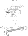
- FIG. 6 is a view schematically illustrating a state in which a handle operating member according to an embodiment of the present disclosure is provided in a circuit breaker
- FIG. 7 is a perspective view illustrating a handle operating member according to an embodiment of the present disclosure
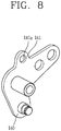
- FIG. 8 is a perspective view illustrating a second link according to an embodiment of the present disclosure
- FIG. 9 is a side view illustrating a state in which a handle operating member according to an embodiment of the present disclosure is connected to a second link.
- FIG. 10 is a perspective view illustrating a state in which a handle operating member according to an embodiment of the present disclosure is connected to a second link
- FIG. 11 is a view schematically illustrating a state in which a handle operating member in an ON state according to an embodiment of the present disclosure is provided within a circuit breaker
- FIG. 12 is a view schematically illustrating a state in which a handle operating member in an OFF state according to an embodiment of the present disclosure is provided within a circuit breaker.
- a circuit breaker includes a handle 100 rotated to an ON or OFF position according to a user manipulation, a first plate 110, to which the handle 100 is rotatably connected, allowing the handle 100 to be attached to a distributing board, a second plate 120 allowing the first plate 110 to be attached to the distributing board, a first link 130 transferring a rotary motion of the handle 100 as a linear motion, a second link 140 rotated according to the linear motion of the first link 130 to provide rotational force enabling the circuit breaker to be switched on or off, a shaft 150 attached to the second plate 120 on the basis of a rotational shaft of the second link 140, a fastening member 160 connecting the first link 130 and the second link 140, and an apparatus for remotely operating a handle for fixing a movement position of the handle 100.
- the apparatus for remotely operating a handle includes a handle operating member 200.
- One side of the handle operating member 200 is connected to the second link 140, and an elastic member 240 such as a spring is provided.
- the handle operating member 200 is rotated according to rotation of the second link 140 to provide elastic force to the second link 140 through the elastic member 240 to fixedly support an ON or OFF position of the handle 100.
- the handle operating member 200 includes a body part 210, a rotary member 220, and a fixing member 230.
- the body part 210 has a cylindrical shape, and the elastic member 240 such as a spring, or the like, providing elastic force is inserted into the body part 210.
- the elastic member 240 such as a spring, or the like, providing elastic force is inserted into the body part 210.
- the rotary member 220 is connected to one side of the body part 210 such that the body part 210 is movable, and rotatably connected to the second plate 120 and rotated cooperatively within a distributing board according to rotation of the handle 100.
- the rotary member 220 includes a bottom plate 221 having an insertion hole 221a to which one side of the body part 210 is movably inserted, and a side plate 223 bent and extending from the bottom plate 221 so as to be rotatably connected to the second plate 220.
- the rotary member 220 is connected to the body part 210 through the bottom plate 221 and rotatably connected to the second plate 120 through the side plate 223.
- One side of the fixing member 230 is connected to the body part 210, and the second link 140 is rotatably connected to the other side of the fixing member 230, so that the fixing member 230 moves together with the body part 210, upon receiving elastic force through the elastic member 240, to rotate the second link 140 at a predetermined angle.
- the fixing member 230 includes a through plate 231 having a through hole (not shown) to which the body part 210 is inserted, side support plates 233 bent to extend from both ends of the through plate 231 and having a fastening hole 239 allowing a fastening member 250 (please refer to FIG. 10 ) to penetrate therethrough, and a space part 235 formed between the side support plates 233 and allowing the second link 140 to be inserted therein.
- a stoppage plate 141 is formed above the second link 140, and a hole 141a is formed in the stoppage plate 141.
- the second link 140 is rotatably connected to the fixing member 230, and upon receiving elastic force in a direction of the second link 140 through the elastic member 240 such as a spring provided in the body part 210, the body part 210 and the fixing member 230 are moved toward the second link 140 to push the second link 140 such that the second link 140 receives rotational force in a clockwise or counterclockwise direction.
- a fixing protrusion 237 fixedly supporting the fastening member 250 is formed on an outer surface of the side support plate 233, and the fixing member 230 and the second link 140 are firmly connected by the fastening member 250 through the fixing protrusion 237.
- a ring member 260 is provided at one side of the body part 210 and positioned between the body part 210 and the bottom plate 221 to prevent the body part 210 from being released.
- a screw is formed at an inner side of the through hole and on an outer circumferential surface of the other side of the body part 210 such that the body part 210 is fastened to the through hole through screw coupling, whereby a length of the body part 210 between the bottom plate 221 and the fixing member 230 is adjusted to adjust an elastic force of the elastic member 240.
- the first link 130 makes a linear motion cooperatively according to the movement of the handle to be moved downwardly, and as the first link 130 is moved downwardly, the second link 140 connected to the first link 130 is also rotated in a clockwise direction cooperatively according to the linear motion of the first link 130.
- the elastic member 240 of the handle operating member 200 pushes the fixing member 230 and the fixing member 230 is moved together with the body part 210 to provide an elastic force in a D1 direction, thereby providing rotational force enabling the second link 140 to be rotated in the clockwise direction.
- the first link 130 connected to the second link 140 receives a force downwardly (D2) due to the rotational force exerted on the second link 140 to be rotated in the clockwise direction, whereby the handle 100 may be stably and firmly maintained in the ON position without being moved.
- a length of the handle operating member 200 is adjusted as the fixing member 230 and the body part 210 connected to the fixing member 230 are moved through the insertion hole 221a formed on the bottom plate 221 according to the rotation of the second link 140, and when the handle 100 is in the OFF position, the fixing member 230 pushes the second link 140 though elastic force of the elastic member 240 to provide an elastic force in a D3 direction to provide rotational force enabling the second link to be rotated in a counterclockwise direction.
- the handle 100 since the handle 100 receives rotational force in the same direction as the rotation direction of the handle 100 through the handle operating member 200, the handle 100 may be smoothly moved.
- the handle operating member 200 When the handle operating member 200 is installed in the circuit breaker, the handle operating member 200 may be installed in an assembled state, thus enhancing convenience of assembling.
Landscapes
- Breakers (AREA)
Claims (7)
- Vorrichtung zum Fernbedienen eines Griffs eines Trennschalters, der einen Griff (100), eine erste Platte (110), mit welcher der Griff (100) drehbar verbunden ist, sodass der Griff (100) an einem Verteiler befestigt werden kann, eine zweite Platte (120), die eine Befestigung des Verteilers an der ersten Platte (110) ermöglicht, eine erste Verbindung (130), die zum Übertragen einer Drehbewegung des Griffs (100) als eine lineare Bewegung ausgelegt ist, und eine zweite Verbindung (140) aufweist, die ausgelegt ist, in Übereinstimmung mit der linearen Bewegung der ersten Verbindung (130) gedreht zu werden, um eine Drehkraft bereitzustellen, die ein Ein- oder Ausschalten des Trennschalters ermöglicht, wobei die Vorrichtung Folgendes umfasst
ein Griffbedienelement (200), das betriebswirksam mit der zweiten Verbindung (140) verbunden ist und ein elastisches Element (240) aufweist, um der zweiten Verbindung (140) eine Federkraft bereitzustellen, während es zusammenwirkend in Übereinstimmung mit einer Drehung der zweiten Verbindung (140) gedreht wird, um eine EIN- und AUS-Position des Griffs (100) fest zu stützen,
wobei die Vorrichtung dadurch gekennzeichnet ist, dass
das Griffbedienelement (200) ein Gehäuseteil (210), in welches das elastische Element (240) eingeführt wird; ein Drehelement (220), das mit einer Seite des Gehäuseteils (210) verbunden ist, sodass das Gehäuseteil (210) in Übereinstimmung mit einer Drehung der zweiten Verbindung (140 beweglich ist und drehbar mit der zweiten Platte (120) verbunden ist; und ein Fixierelement (230) aufweist, dessen eine Seite mit dem Gehäuseteil (210) verbunden ist und dessen andere Seite mit der zweiten Verbindung (140) drehbar verbunden ist, um so eine Federkraft durch das elastische Element (240) aufzunehmen, und
eine Sperrplatte (141) über der zweiten Verbindung (140) ausgebildet ist, ein Loch (141a) in der Sperrplatte (141) ausgebildet ist und das Fixierelement (230) eine Durchgangsplatte (231) mit einem Durchgangsloch aufweist, in welches das Gehäuseteil (210) eingeführt wird, Seitenstützplatten (233), die derart gebogen sind, dass sie sich von beiden Enden der Durchgangsplatte (231) erstrecken und ein Befestigungsloch (239) aufweisen, das ermöglicht, dass ein Befestigungselement (250) dort hindurch dringen kann, und ein Beabstandungsteil (235) aufweist, das zwischen den Seitenstützplatten (233) ausgebildet ist und ermöglicht, dass die Sperrplatte (141) dort eingesetzt wird, wobei in einem Zustand, in dem die Sperrplatte (141) in das Beabstandungsteil (235) eingesetzt ist, das Befestigungselement (250) durch das Loch (141a) und das Beabstandungsteil (235) dringt, wodurch die zweite Verbindung (140) drehbar mit dem Fixierelement (230) verbunden wird. - Vorrichtung nach Anspruch 1, wobei das Drehelement (220) eine untere Platte (221) mit einem Einsetzloch (221a), in welches das Gehäuseteil (210) beweglich eingesetzt ist, und eine Seitenplatte (223) aufweist, die gebogen ist und sich von der unteren Platte (221) derart erstreckt, dass sie drehbar mit der zweiten Platte (220) verbunden wird.
- Vorrichtung nach Anspruch 1 oder 2, wobei das Griffbedienelement (200) nach oben angeordnet ist, um in einem vorbestimmten Winkel in Übereinstimmung mit einer Drehung der zweiten Verbindung (140) angeordnet zu werden, um dem Fixierelement (230) durch das elastische Element (240) eine Federkraft bereitzustellen, um der zweiten Verbindung (140) eine Drehkraft bereitzustellen, wenn der Griff (100) in die EIN-Position bewegt wird, und wobei das Griffbedienelement (200) ausgelegt ist, um nach unten in einem vorbestimmten Winkel in Übereinstimmung mit einer Drehung der zweiten Verbindung gedreht zu werden, um dem Fixierelement (230) durch das elastische Element (240) eine Federkraft bereitzustellen, um der zweiten Verbindung (140) eine Drehkraft bereitzustellen, wenn der Griff (100) in die AUS-Position bewegt wird.
- Vorrichtung nach Anspruch 3, wobei die zweite Verbindung (140) ausgelegt ist, eine Drehkraft aufzunehmen, um in einer Richtung im Uhrzeigersinn durch das elastische Element gedreht zu werden, wenn der Griff (100) in die EIN-Position bewegt wird, und wobei die zweite Verbindung (140) ausgelegt ist, eine Drehkraft aufzunehmen, um in einer Richtung entgegen dem Uhrzeigersinn durch das elastische Element gedreht zu werden, wenn der Griff in die AUS-Position bewegt wird.
- Vorrichtung nach Anspruch 1, wobei ein Fixiervorsprung (237) auf einer äußeren Oberfläche jeder der Seitenplatten (233) ausgebildet ist, um das Befestigungselement (250) fest zu stützen.
- Vorrichtung nach Anspruch 2, wobei ein Ringelement (260) auf einer Seite des Gehäuseteils (210) bereitgestellt und zwischen der unteren Platte (221) und dem Gehäuseteil (210) bereitgestellt ist, um eine Ablösung des Gehäuseteils (210) zu verhindern.
- Vorrichtung nach Anspruch 1, wobei eine Schraube auf einer Innenseite des Durchgangslochs und auf einer äußeren Umfangsoberfläche der anderen Seite des Gehäuseteils (210) ausgebildet ist und eine Länge des Gehäuseteils (210) eingestellt wird, während das Gehäuseteil (210) mit dem Durchgangsloch verschraubt wird.
Applications Claiming Priority (1)
| Application Number | Priority Date | Filing Date | Title |
|---|---|---|---|
| KR1020140172430A KR101598422B1 (ko) | 2014-12-03 | 2014-12-03 | 배선용 차단기의 원방 핸들 조작 장치 |
Publications (2)
| Publication Number | Publication Date |
|---|---|
| EP3029699A1 EP3029699A1 (de) | 2016-06-08 |
| EP3029699B1 true EP3029699B1 (de) | 2017-09-20 |
Family
ID=54707629
Family Applications (1)
| Application Number | Title | Priority Date | Filing Date |
|---|---|---|---|
| EP15196644.7A Not-in-force EP3029699B1 (de) | 2014-12-03 | 2015-11-27 | Vorrichtung zum fernbedienen des griffes eines schutzschalters |
Country Status (5)
| Country | Link |
|---|---|
| US (1) | US9773630B2 (de) |
| EP (1) | EP3029699B1 (de) |
| KR (1) | KR101598422B1 (de) |
| CN (1) | CN105679614B (de) |
| ES (1) | ES2650873T3 (de) |
Families Citing this family (4)
| Publication number | Priority date | Publication date | Assignee | Title |
|---|---|---|---|---|
| KR101743615B1 (ko) * | 2016-10-24 | 2017-06-07 | 주식회사 나로이엔씨 | 공동주택의 분전상태 제어를 위한 스위치 |
| KR101839090B1 (ko) * | 2016-11-02 | 2018-04-26 | 엘에스산전 주식회사 | 기중차단기의 배전반 도어 록 장치 |
| KR101919277B1 (ko) * | 2018-04-07 | 2018-11-15 | 박재덕 | 배전반용 다중 도어의 순차오픈장치 |
| KR102271519B1 (ko) * | 2019-11-18 | 2021-07-01 | 엘에스일렉트릭(주) | 크로스바 조립체 및 이를 포함하는 트립 장치 |
Family Cites Families (10)
| Publication number | Priority date | Publication date | Assignee | Title |
|---|---|---|---|---|
| US3272953A (en) * | 1965-02-08 | 1966-09-13 | Gen Electric | External actuator handle mechanism for enclosed circuit breaker |
| US3629536A (en) * | 1970-10-16 | 1971-12-21 | Square D Co | Switch enclosure with sealing means operable by switch-operating |
| US3768321A (en) * | 1972-02-28 | 1973-10-30 | Square D Co | Safety switch operating mechanism |
| US3777084A (en) * | 1972-09-20 | 1973-12-04 | Square D Co | Safety switch with sealable cover and interlock means for preventing operation of sealing means when cover is fully open |
| US3879589A (en) * | 1973-03-02 | 1975-04-22 | Square D Co | Safety switch having improved operating mechanism and interlock means |
| US4168417A (en) * | 1978-01-25 | 1979-09-18 | Square D Company | Remote operating mechanism for electric switches |
| JP3523948B2 (ja) * | 1995-10-30 | 2004-04-26 | 寺崎電気産業株式会社 | 引出型回路遮断器の位置表示スイッチ装置 |
| KR20040069030A (ko) | 2003-01-28 | 2004-08-04 | 노진석 | 박판형 커런트 트랜스포머 |
| KR200469030Y1 (ko) * | 2012-09-14 | 2013-09-12 | 엘에스산전 주식회사 | 차단기의 핸들 인터록 장치 |
| KR200472734Y1 (ko) * | 2012-09-14 | 2014-05-19 | 엘에스산전 주식회사 | 차단기의 핸들 인터록 장치 |
-
2014
- 2014-12-03 KR KR1020140172430A patent/KR101598422B1/ko active Active
-
2015
- 2015-11-27 EP EP15196644.7A patent/EP3029699B1/de not_active Not-in-force
- 2015-11-27 ES ES15196644.7T patent/ES2650873T3/es active Active
- 2015-11-30 US US14/954,842 patent/US9773630B2/en active Active
- 2015-12-02 CN CN201510873215.9A patent/CN105679614B/zh active Active
Non-Patent Citations (1)
| Title |
|---|
| None * |
Also Published As
| Publication number | Publication date |
|---|---|
| US9773630B2 (en) | 2017-09-26 |
| EP3029699A1 (de) | 2016-06-08 |
| CN105679614B (zh) | 2018-01-12 |
| US20160163490A1 (en) | 2016-06-09 |
| CN105679614A (zh) | 2016-06-15 |
| ES2650873T3 (es) | 2018-01-22 |
| KR101598422B1 (ko) | 2016-02-29 |
Similar Documents
| Publication | Publication Date | Title |
|---|---|---|
| US9773630B2 (en) | Apparatus for remotely operating handle of circuit breaker | |
| EP3319104B1 (de) | Türverriegelungsvorrichtung eines verteilerschranks für einen luftleistungsschalter | |
| CN104347324B (zh) | 断路器 | |
| JP6280165B2 (ja) | リングメインユニットのインターロック装置 | |
| US9865407B2 (en) | Interlock apparatus of ring main unit | |
| CN111712897A (zh) | 断路器 | |
| EP3343710B1 (de) | Positionsanzeiger für einen leistungsschalter | |
| US20140353133A1 (en) | Locking mechanism for a switch-on button of a circuit breaker | |
| EP2806447B1 (de) | Kupplungsvorrichtung für einen Trennschalter | |
| US10256052B2 (en) | Integrated interlock device of air circuit breaker and method of using the same | |
| CN204614743U (zh) | 具有限位装置的跳扣组件 | |
| WO2016107364A1 (zh) | 小型断路器的热式可调脱扣装置 | |
| KR101869721B1 (ko) | 가스절연 개폐장치용 퓨즈 타입 메커니즘 인터록 장치 | |
| KR102067391B1 (ko) | 배선용 차단기 | |
| US12548725B2 (en) | Device for switching a handle of an electrical switch, and multi-function drive having a device of this type | |
| KR102081698B1 (ko) | 배선용 차단기 | |
| KR200466294Y1 (ko) | 배선차단기의 한류 트립구조 | |
| CN103348431B (zh) | 电开关设备 | |
| KR101163727B1 (ko) | 차단기용 외부조작핸들장치 | |
| CN106169399B (zh) | 一种联锁机构、具备该联锁机构的电控设备以及断路器 | |
| CN105810520B (zh) | 操作断路器的方法和断路器 | |
| CN102893356B (zh) | 电气安装开关装置 | |
| EP2947673B1 (de) | Auslösemechanismus für Schaltvorrichtung für niedrige und mittlere Spannungen | |
| KR100896746B1 (ko) | 누전·배선용 차단기의 개폐기구 | |
| KR20160122354A (ko) | 래치 이탈 방지 기능을 갖는 차단기 |
Legal Events
| Date | Code | Title | Description |
|---|---|---|---|
| PUAI | Public reference made under article 153(3) epc to a published international application that has entered the european phase |
Free format text: ORIGINAL CODE: 0009012 |
|
| AK | Designated contracting states |
Kind code of ref document: A1 Designated state(s): AL AT BE BG CH CY CZ DE DK EE ES FI FR GB GR HR HU IE IS IT LI LT LU LV MC MK MT NL NO PL PT RO RS SE SI SK SM TR |
|
| AX | Request for extension of the european patent |
Extension state: BA ME |
|
| STAA | Information on the status of an ep patent application or granted ep patent |
Free format text: STATUS: REQUEST FOR EXAMINATION WAS MADE |
|
| 17P | Request for examination filed |
Effective date: 20161206 |
|
| RBV | Designated contracting states (corrected) |
Designated state(s): AL AT BE BG CH CY CZ DE DK EE ES FI FR GB GR HR HU IE IS IT LI LT LU LV MC MK MT NL NO PL PT RO RS SE SI SK SM TR |
|
| R17P | Request for examination filed (corrected) |
Effective date: 20161206 |
|
| GRAP | Despatch of communication of intention to grant a patent |
Free format text: ORIGINAL CODE: EPIDOSNIGR1 |
|
| STAA | Information on the status of an ep patent application or granted ep patent |
Free format text: STATUS: GRANT OF PATENT IS INTENDED |
|
| RIC1 | Information provided on ipc code assigned before grant |
Ipc: H01H 9/22 20060101AFI20170328BHEP Ipc: H01H 73/24 20060101ALN20170328BHEP Ipc: H01H 71/52 20060101ALI20170328BHEP |
|
| INTG | Intention to grant announced |
Effective date: 20170421 |
|
| GRAS | Grant fee paid |
Free format text: ORIGINAL CODE: EPIDOSNIGR3 |
|
| GRAA | (expected) grant |
Free format text: ORIGINAL CODE: 0009210 |
|
| STAA | Information on the status of an ep patent application or granted ep patent |
Free format text: STATUS: THE PATENT HAS BEEN GRANTED |
|
| AK | Designated contracting states |
Kind code of ref document: B1 Designated state(s): AL AT BE BG CH CY CZ DE DK EE ES FI FR GB GR HR HU IE IS IT LI LT LU LV MC MK MT NL NO PL PT RO RS SE SI SK SM TR |
|
| REG | Reference to a national code |
Ref country code: GB Ref legal event code: FG4D |
|
| REG | Reference to a national code |
Ref country code: CH Ref legal event code: EP |
|
| REG | Reference to a national code |
Ref country code: AT Ref legal event code: REF Ref document number: 930767 Country of ref document: AT Kind code of ref document: T Effective date: 20171015 |
|
| REG | Reference to a national code |
Ref country code: IE Ref legal event code: FG4D |
|
| REG | Reference to a national code |
Ref country code: DE Ref legal event code: R096 Ref document number: 602015004877 Country of ref document: DE |
|
| REG | Reference to a national code |
Ref country code: FR Ref legal event code: PLFP Year of fee payment: 3 |
|
| REG | Reference to a national code |
Ref country code: ES Ref legal event code: FG2A Ref document number: 2650873 Country of ref document: ES Kind code of ref document: T3 Effective date: 20180122 |
|
| REG | Reference to a national code |
Ref country code: NL Ref legal event code: MP Effective date: 20170920 |
|
| PG25 | Lapsed in a contracting state [announced via postgrant information from national office to epo] |
Ref country code: HR Free format text: LAPSE BECAUSE OF FAILURE TO SUBMIT A TRANSLATION OF THE DESCRIPTION OR TO PAY THE FEE WITHIN THE PRESCRIBED TIME-LIMIT Effective date: 20170920 Ref country code: FI Free format text: LAPSE BECAUSE OF FAILURE TO SUBMIT A TRANSLATION OF THE DESCRIPTION OR TO PAY THE FEE WITHIN THE PRESCRIBED TIME-LIMIT Effective date: 20170920 Ref country code: NO Free format text: LAPSE BECAUSE OF FAILURE TO SUBMIT A TRANSLATION OF THE DESCRIPTION OR TO PAY THE FEE WITHIN THE PRESCRIBED TIME-LIMIT Effective date: 20171220 Ref country code: LT Free format text: LAPSE BECAUSE OF FAILURE TO SUBMIT A TRANSLATION OF THE DESCRIPTION OR TO PAY THE FEE WITHIN THE PRESCRIBED TIME-LIMIT Effective date: 20170920 Ref country code: SE Free format text: LAPSE BECAUSE OF FAILURE TO SUBMIT A TRANSLATION OF THE DESCRIPTION OR TO PAY THE FEE WITHIN THE PRESCRIBED TIME-LIMIT Effective date: 20170920 |
|
| REG | Reference to a national code |
Ref country code: LT Ref legal event code: MG4D |
|
| REG | Reference to a national code |
Ref country code: AT Ref legal event code: MK05 Ref document number: 930767 Country of ref document: AT Kind code of ref document: T Effective date: 20170920 |
|
| PG25 | Lapsed in a contracting state [announced via postgrant information from national office to epo] |
Ref country code: LV Free format text: LAPSE BECAUSE OF FAILURE TO SUBMIT A TRANSLATION OF THE DESCRIPTION OR TO PAY THE FEE WITHIN THE PRESCRIBED TIME-LIMIT Effective date: 20170920 Ref country code: BG Free format text: LAPSE BECAUSE OF FAILURE TO SUBMIT A TRANSLATION OF THE DESCRIPTION OR TO PAY THE FEE WITHIN THE PRESCRIBED TIME-LIMIT Effective date: 20171220 Ref country code: RS Free format text: LAPSE BECAUSE OF FAILURE TO SUBMIT A TRANSLATION OF THE DESCRIPTION OR TO PAY THE FEE WITHIN THE PRESCRIBED TIME-LIMIT Effective date: 20170920 Ref country code: GR Free format text: LAPSE BECAUSE OF FAILURE TO SUBMIT A TRANSLATION OF THE DESCRIPTION OR TO PAY THE FEE WITHIN THE PRESCRIBED TIME-LIMIT Effective date: 20171221 |
|
| PG25 | Lapsed in a contracting state [announced via postgrant information from national office to epo] |
Ref country code: NL Free format text: LAPSE BECAUSE OF FAILURE TO SUBMIT A TRANSLATION OF THE DESCRIPTION OR TO PAY THE FEE WITHIN THE PRESCRIBED TIME-LIMIT Effective date: 20170920 |
|
| PG25 | Lapsed in a contracting state [announced via postgrant information from national office to epo] |
Ref country code: RO Free format text: LAPSE BECAUSE OF FAILURE TO SUBMIT A TRANSLATION OF THE DESCRIPTION OR TO PAY THE FEE WITHIN THE PRESCRIBED TIME-LIMIT Effective date: 20170920 Ref country code: PL Free format text: LAPSE BECAUSE OF FAILURE TO SUBMIT A TRANSLATION OF THE DESCRIPTION OR TO PAY THE FEE WITHIN THE PRESCRIBED TIME-LIMIT Effective date: 20170920 Ref country code: CZ Free format text: LAPSE BECAUSE OF FAILURE TO SUBMIT A TRANSLATION OF THE DESCRIPTION OR TO PAY THE FEE WITHIN THE PRESCRIBED TIME-LIMIT Effective date: 20170920 |
|
| PG25 | Lapsed in a contracting state [announced via postgrant information from national office to epo] |
Ref country code: AT Free format text: LAPSE BECAUSE OF FAILURE TO SUBMIT A TRANSLATION OF THE DESCRIPTION OR TO PAY THE FEE WITHIN THE PRESCRIBED TIME-LIMIT Effective date: 20170920 Ref country code: SM Free format text: LAPSE BECAUSE OF FAILURE TO SUBMIT A TRANSLATION OF THE DESCRIPTION OR TO PAY THE FEE WITHIN THE PRESCRIBED TIME-LIMIT Effective date: 20170920 Ref country code: IS Free format text: LAPSE BECAUSE OF FAILURE TO SUBMIT A TRANSLATION OF THE DESCRIPTION OR TO PAY THE FEE WITHIN THE PRESCRIBED TIME-LIMIT Effective date: 20180120 Ref country code: EE Free format text: LAPSE BECAUSE OF FAILURE TO SUBMIT A TRANSLATION OF THE DESCRIPTION OR TO PAY THE FEE WITHIN THE PRESCRIBED TIME-LIMIT Effective date: 20170920 Ref country code: SK Free format text: LAPSE BECAUSE OF FAILURE TO SUBMIT A TRANSLATION OF THE DESCRIPTION OR TO PAY THE FEE WITHIN THE PRESCRIBED TIME-LIMIT Effective date: 20170920 |
|
| REG | Reference to a national code |
Ref country code: DE Ref legal event code: R097 Ref document number: 602015004877 Country of ref document: DE |
|
| PG25 | Lapsed in a contracting state [announced via postgrant information from national office to epo] |
Ref country code: MC Free format text: LAPSE BECAUSE OF FAILURE TO SUBMIT A TRANSLATION OF THE DESCRIPTION OR TO PAY THE FEE WITHIN THE PRESCRIBED TIME-LIMIT Effective date: 20170920 |
|
| PLBE | No opposition filed within time limit |
Free format text: ORIGINAL CODE: 0009261 |
|
| STAA | Information on the status of an ep patent application or granted ep patent |
Free format text: STATUS: NO OPPOSITION FILED WITHIN TIME LIMIT |
|
| PG25 | Lapsed in a contracting state [announced via postgrant information from national office to epo] |
Ref country code: DK Free format text: LAPSE BECAUSE OF FAILURE TO SUBMIT A TRANSLATION OF THE DESCRIPTION OR TO PAY THE FEE WITHIN THE PRESCRIBED TIME-LIMIT Effective date: 20170920 |
|
| 26N | No opposition filed |
Effective date: 20180621 |
|
| PG25 | Lapsed in a contracting state [announced via postgrant information from national office to epo] |
Ref country code: LU Free format text: LAPSE BECAUSE OF NON-PAYMENT OF DUE FEES Effective date: 20171127 |
|
| REG | Reference to a national code |
Ref country code: BE Ref legal event code: MM Effective date: 20171130 |
|
| REG | Reference to a national code |
Ref country code: IE Ref legal event code: MM4A |
|
| REG | Reference to a national code |
Ref country code: FR Ref legal event code: PLFP Year of fee payment: 4 |
|
| PG25 | Lapsed in a contracting state [announced via postgrant information from national office to epo] |
Ref country code: MT Free format text: LAPSE BECAUSE OF NON-PAYMENT OF DUE FEES Effective date: 20171127 |
|
| PG25 | Lapsed in a contracting state [announced via postgrant information from national office to epo] |
Ref country code: IE Free format text: LAPSE BECAUSE OF NON-PAYMENT OF DUE FEES Effective date: 20171127 |
|
| PG25 | Lapsed in a contracting state [announced via postgrant information from national office to epo] |
Ref country code: SI Free format text: LAPSE BECAUSE OF FAILURE TO SUBMIT A TRANSLATION OF THE DESCRIPTION OR TO PAY THE FEE WITHIN THE PRESCRIBED TIME-LIMIT Effective date: 20170920 Ref country code: BE Free format text: LAPSE BECAUSE OF NON-PAYMENT OF DUE FEES Effective date: 20171130 |
|
| PG25 | Lapsed in a contracting state [announced via postgrant information from national office to epo] |
Ref country code: HU Free format text: LAPSE BECAUSE OF FAILURE TO SUBMIT A TRANSLATION OF THE DESCRIPTION OR TO PAY THE FEE WITHIN THE PRESCRIBED TIME-LIMIT; INVALID AB INITIO Effective date: 20151127 |
|
| REG | Reference to a national code |
Ref country code: CH Ref legal event code: PL |
|
| PG25 | Lapsed in a contracting state [announced via postgrant information from national office to epo] |
Ref country code: LI Free format text: LAPSE BECAUSE OF NON-PAYMENT OF DUE FEES Effective date: 20181130 Ref country code: CH Free format text: LAPSE BECAUSE OF NON-PAYMENT OF DUE FEES Effective date: 20181130 |
|
| PG25 | Lapsed in a contracting state [announced via postgrant information from national office to epo] |
Ref country code: CY Free format text: LAPSE BECAUSE OF FAILURE TO SUBMIT A TRANSLATION OF THE DESCRIPTION OR TO PAY THE FEE WITHIN THE PRESCRIBED TIME-LIMIT Effective date: 20170920 |
|
| PG25 | Lapsed in a contracting state [announced via postgrant information from national office to epo] |
Ref country code: MK Free format text: LAPSE BECAUSE OF FAILURE TO SUBMIT A TRANSLATION OF THE DESCRIPTION OR TO PAY THE FEE WITHIN THE PRESCRIBED TIME-LIMIT Effective date: 20170920 |
|
| PG25 | Lapsed in a contracting state [announced via postgrant information from national office to epo] |
Ref country code: TR Free format text: LAPSE BECAUSE OF FAILURE TO SUBMIT A TRANSLATION OF THE DESCRIPTION OR TO PAY THE FEE WITHIN THE PRESCRIBED TIME-LIMIT Effective date: 20170920 |
|
| PG25 | Lapsed in a contracting state [announced via postgrant information from national office to epo] |
Ref country code: PT Free format text: LAPSE BECAUSE OF FAILURE TO SUBMIT A TRANSLATION OF THE DESCRIPTION OR TO PAY THE FEE WITHIN THE PRESCRIBED TIME-LIMIT Effective date: 20170920 |
|
| PG25 | Lapsed in a contracting state [announced via postgrant information from national office to epo] |
Ref country code: AL Free format text: LAPSE BECAUSE OF FAILURE TO SUBMIT A TRANSLATION OF THE DESCRIPTION OR TO PAY THE FEE WITHIN THE PRESCRIBED TIME-LIMIT Effective date: 20170920 |
|
| PGFP | Annual fee paid to national office [announced via postgrant information from national office to epo] |
Ref country code: IT Payment date: 20220906 Year of fee payment: 8 Ref country code: GB Payment date: 20220905 Year of fee payment: 8 |
|
| PGFP | Annual fee paid to national office [announced via postgrant information from national office to epo] |
Ref country code: FR Payment date: 20220905 Year of fee payment: 8 |
|
| PGFP | Annual fee paid to national office [announced via postgrant information from national office to epo] |
Ref country code: ES Payment date: 20221209 Year of fee payment: 8 Ref country code: DE Payment date: 20220603 Year of fee payment: 8 |
|
| REG | Reference to a national code |
Ref country code: DE Ref legal event code: R119 Ref document number: 602015004877 Country of ref document: DE |
|
| GBPC | Gb: european patent ceased through non-payment of renewal fee |
Effective date: 20231127 |
|
| PG25 | Lapsed in a contracting state [announced via postgrant information from national office to epo] |
Ref country code: DE Free format text: LAPSE BECAUSE OF NON-PAYMENT OF DUE FEES Effective date: 20240601 |
|
| PG25 | Lapsed in a contracting state [announced via postgrant information from national office to epo] |
Ref country code: GB Free format text: LAPSE BECAUSE OF NON-PAYMENT OF DUE FEES Effective date: 20231127 |
|
| PG25 | Lapsed in a contracting state [announced via postgrant information from national office to epo] |
Ref country code: FR Free format text: LAPSE BECAUSE OF NON-PAYMENT OF DUE FEES Effective date: 20231130 |
|
| PG25 | Lapsed in a contracting state [announced via postgrant information from national office to epo] |
Ref country code: GB Free format text: LAPSE BECAUSE OF NON-PAYMENT OF DUE FEES Effective date: 20231127 Ref country code: FR Free format text: LAPSE BECAUSE OF NON-PAYMENT OF DUE FEES Effective date: 20231130 Ref country code: DE Free format text: LAPSE BECAUSE OF NON-PAYMENT OF DUE FEES Effective date: 20240601 |
|
| PG25 | Lapsed in a contracting state [announced via postgrant information from national office to epo] |
Ref country code: IT Free format text: LAPSE BECAUSE OF NON-PAYMENT OF DUE FEES Effective date: 20231127 |
|
| PG25 | Lapsed in a contracting state [announced via postgrant information from national office to epo] |
Ref country code: IT Free format text: LAPSE BECAUSE OF NON-PAYMENT OF DUE FEES Effective date: 20231127 |
|
| REG | Reference to a national code |
Ref country code: ES Ref legal event code: FD2A Effective date: 20250108 |
|
| PG25 | Lapsed in a contracting state [announced via postgrant information from national office to epo] |
Ref country code: ES Free format text: LAPSE BECAUSE OF NON-PAYMENT OF DUE FEES Effective date: 20231128 |
|
| PG25 | Lapsed in a contracting state [announced via postgrant information from national office to epo] |
Ref country code: ES Free format text: LAPSE BECAUSE OF NON-PAYMENT OF DUE FEES Effective date: 20231128 |