EP3029355A1 - Spannrolle - Google Patents
Spannrolle Download PDFInfo
- Publication number
- EP3029355A1 EP3029355A1 EP15194208.3A EP15194208A EP3029355A1 EP 3029355 A1 EP3029355 A1 EP 3029355A1 EP 15194208 A EP15194208 A EP 15194208A EP 3029355 A1 EP3029355 A1 EP 3029355A1
- Authority
- EP
- European Patent Office
- Prior art keywords
- roller
- saucer
- sealing
- tubular arm
- belt
- Prior art date
- Legal status (The legal status is an assumption and is not a legal conclusion. Google has not performed a legal analysis and makes no representation as to the accuracy of the status listed.)
- Granted
Links
Images


Classifications
-
- F—MECHANICAL ENGINEERING; LIGHTING; HEATING; WEAPONS; BLASTING
- F16—ENGINEERING ELEMENTS AND UNITS; GENERAL MEASURES FOR PRODUCING AND MAINTAINING EFFECTIVE FUNCTIONING OF MACHINES OR INSTALLATIONS; THERMAL INSULATION IN GENERAL
- F16H—GEARING
- F16H7/00—Gearings for conveying rotary motion by endless flexible members
- F16H7/08—Means for varying tension of belts, ropes or chains
- F16H2007/0802—Actuators for final output members
- F16H2007/081—Torsion springs
-
- F—MECHANICAL ENGINEERING; LIGHTING; HEATING; WEAPONS; BLASTING
- F16—ENGINEERING ELEMENTS AND UNITS; GENERAL MEASURES FOR PRODUCING AND MAINTAINING EFFECTIVE FUNCTIONING OF MACHINES OR INSTALLATIONS; THERMAL INSULATION IN GENERAL
- F16H—GEARING
- F16H7/00—Gearings for conveying rotary motion by endless flexible members
- F16H7/08—Means for varying tension of belts, ropes or chains
- F16H2007/0863—Finally actuated members, e.g. constructional details thereof
- F16H2007/0865—Pulleys
-
- F—MECHANICAL ENGINEERING; LIGHTING; HEATING; WEAPONS; BLASTING
- F16—ENGINEERING ELEMENTS AND UNITS; GENERAL MEASURES FOR PRODUCING AND MAINTAINING EFFECTIVE FUNCTIONING OF MACHINES OR INSTALLATIONS; THERMAL INSULATION IN GENERAL
- F16H—GEARING
- F16H7/00—Gearings for conveying rotary motion by endless flexible members
- F16H7/08—Means for varying tension of belts, ropes or chains
- F16H2007/0889—Path of movement of the finally actuated member
- F16H2007/0893—Circular path
Definitions
- the present invention relates to a tensioning roller of an internal combustion engine of a motor vehicle.
- the present invention relates more particularly to a device for cocking a tensioning roller for a belt change.
- the internal combustion engines or heat are associated with accessory systems necessary for the operation of said engine.
- a pump allows a flow of fluid for cooling the motor during operation.
- an alternator makes it possible to charge an electric battery to supply the electrical energy essential to the various electric motor systems associated with the proper functioning of the heat engine, such as, for example, a control unit.
- Said means are activated synchronously to the operation of the engine by one or more accessory belts arranged generally parallel to an accessory face of the engine.
- the accessory belt surrounds a fixed gearwheel integral with a crankshaft end and one or more fixed gears integral with accessory shafts. It provides friction training with the gear wheel and driven sprockets.
- Said belt is in known manner from polymeric material and fabric and it must be changed according to wear. To do this, a clearance is produced between the belt and the toothed wheel and driven sprockets, said belt is then relaxed and can be extracted from its housing.
- a tensioning of the accessory belt is carried out using tensioning rollers which are advantageously arranged on the path of the belt to ensure optimum tension of the belt.
- the tensioning roller thus makes it possible to tension the belt and to favor the winding of the latter around the pulleys of accessories (alternator, compressor, etc.).
- the tensioner roller is essentially a means to increase the path of the belt.
- Belt path means the path followed by a reference point of the belt around the contact elements including the gear wheel, the driven gears and the rollers.
- the tensioner roller may also allow the belt to be temporarily relaxed by temporarily shortening said belt path in order to be able to remove said belt.
- said fastening means can be hidden by the belt and are therefore little or not accessible.
- fastening screws may comprise specific heads requiring a tool change during the extraction operation of the belt.
- Tensioning rollers are also known comprising elastic means for tensioning the belt and a bearing around which the belt is arranged.
- the axis of the bearing may include a point of attachment for a tool to relax the belt during the change of said belt.
- this operation which involves a rotation in the counter-clockwise direction, may also have the effect of releasing an inner ring of the bearing, which adds an important safety fault of the operation of the belt.
- said roller comprises a coupling device of the sealing saucer with the support plate.
- the coupling device makes it possible to prevent a relative movement of rotation between the sealing cup and the support plate.
- Said saucer thus makes it possible to transmit rotational forces to the support plate.
- said hooking means carries an interface means with a screwing tool.
- Said interface means makes it possible not to change the screwing tool during the operation of changing the belt.
- a belt 11 partially surrounds a tensioner roller 10 for substantially varying the path of said belt to ensure belt tension and optimum contact of said belt with a toothed wheel (not shown) secured to a belt.
- end of the crankshaft and with the driven pinion 12 attached to one end of an accessory rotation shaft.
- Said accessories are in a list including a water pump, an alternator, a power steering pump. Said ends open from a face of the motor housing known as the accessory face 13 of said housing.
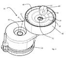
- the figure 2 represents a tensioning roller known in the state of the art.
- the tensioning roller 10 comprises a support plate 14 held by a roller foot 15 which is fixed to the wall of the accessory face 13 of the motor by one or more fastening screws 19.
- Said support plate is pivotally movable around the X1 axis of said roller foot 15 in the anti-clockwise direction between an end stop position 16 and a maintenance transient position 17.
- Elastic means 18 are able to return said support plate 14 to the stop position 16. can thus rotate the support plate from the stop position 16 to the maintenance position 17 to reduce the tension on the belt, said maintenance position corresponds for example to the creation of a radial clearance between the belt 11 and the tensioner roller 10. This clearance then allows the removal of the belt for replacement.
- the support plate 14 is extended at the radial peripheral edge by a maintenance finger 20 which extends along an axis substantially parallel to that of the roller foot 15, said maintenance finger has a form that can be grasped by a screwing tool.
- the enterable shape has a hexagonal head.
- the support plate 14 is extended by a tubular arm 21 of rotation disposed substantially diametrically opposite the maintenance finger 20 relative to the axis of the foot 15.
- Said tubular arm 21 extends along a substantially parallel axis X 2 to the axis X1 of the roller foot and it is intended to accommodate a friction reduction means 40 which is here a rolling.
- the bearing comprises an inner ring 41 which is mounted around the tubular rotating arm 21 bearing on the support plate 14, and an outer ring 42 surrounded by the belt 11.
- the stop position 16 of the support plate 14 corresponds to a support of the outer ring 42 of the friction reduction means 40 against the belt 11 to allow tensioning of said belt 11.
- the tensioner roller 10 comprises in the upper part 22 opposite the accessory face 13 of the housing a sealing cup 26 intended to isolate the components of the friction reduction means against impurities or dusts which are liable to deteriorate the operation of said reduction means friction 40.
- the sealing cup 26 has a substantially circular shape and covers an upper radial face of the bearing 40 and comprises a fixing orifice 24 in the extension of the inner chamber 25 of the tubular arm 21, said fixing orifice is traversed by a fixing screw driven into said inner chamber 25 of the tubular arm 21. In its operating position, the sealing cup 26 is mounted in abutment against the inner ring of the bearing.
- the provision of the maintenance finger 20 therefore causes greater space to take into account the different jigs or sets of parts during the operation of changing the belt 11.
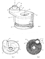
- the tensioning roller 10 comprises a sealing cup 26 and fastening means adapted to make the sealing soup 26 and the support plate 14 integral in rotation.
- the sealing saucer 26 comprises a fixing orifice 24 intended to be traversed by a fixing screw and an axial connecting finger 27 which extends from the edge of said fixing orifice 24, along the axis X 2 of said orifice and to the accessory side 13 of the motor housing.
- Said connecting finger 27 is obtained by stamping and does not encroach on the section of the fixing orifice 24.
- the tubular arm of rotation 21 extends from the support plate 14 by a lower end 28. It may for example be attached to said plate by welding or be part of said support plate by molding.
- Said tubular rotating arm 21 comprises at an opposite upper end 29 a notch 30 substantially complementary to the connecting finger 27 of the sealing saucer.
- said connecting finger 27 is received in said notch 30 of the rotating arm with a small clearance less than 1 / 10mm.
- the fastening screw is then pushed through the fixing orifice 24 into the tubular rotating arm 21 and pushes and holds the connecting finger 27 of the sealing cup 26 in the notch 30 of the rotation arm 21.
- the sealing saucer is then secured in rotation with the tubular arm of rotation and therefore with the support plate 14. It is then possible to manipulate the sealing saucer 26 in a pivoting manner about the axis of the roller foot 15, which causes the support plate 14 to pivot about the same foot.
- the sealing saucer 26 comprises on an upper face facing away from the accessory face 13 of the housing a hooking means 31.
- Said hooking means extends substantially orthogonal to said saucer and serves as a finger 20. It has a shape preferably gripped by a screwdriver.
- Said enterable form of the maintenance finger can be a boss comprising an interface means for the screwing tool such as a head shape hexagonal represented in the figures 5 or 7 , or it may include walls that surround a hexagonal head as shown in the figure 8 or it may comprise a hexagon screw fixed against the upper face of the saucer (not shown).
- the screwing tool can hook said maintenance finger 20 to pivotably move the sealing cup 26 around the axis X1 of the roller foot 15, thereby causing rotation about the same axis of the support plate 14.
- the same screwing tool can be used for screwing / unscrewing the fixing screws 19 of the roller foot.
- the tubular arm 21 is extended by its upper end 29 along the axis of the arm by a connecting tooth 32 peripheral edge.
- Said connecting tooth 32 is received in a substantially complementary notch 33 dug from the edge of the fastening orifice 24 of the sealing saucer 26.
- said connecting tooth 32 does not have a length sufficient to exceed the upper face of the sealing saucer 26 once it mounted so as not to interfere with the fixing of said saucer.
- the fixing screw allows the axial retention of said saucer 26 against said arm 21.
- the sealing saucer 26 comprises a ring bearing a toothing facing the accessory face 13 of the housing.
- the tubular rotating arm 21 carries at its upper end 29 also a toothing substantially complementary to the toothing of the sealing saucer.
- the teeth may comprise cleats having teeth along the axis X2, or a groove of the tubular arm rotation 21 engaged in a complementary groove in said crown of the sealing saucer.
- the toothing of the saucer is engaged in the complementary toothing of the rotational tubular arm to make the sealing saucer 26 and the rotation arm 21 integral in rotation.
- the fastening screw enables said saucer to be held axially. against said arm 21.
- the tensioning roller 10 comprises a coupling device of the sealing saucer 26 with the rotation arm 21 and thus also with the support plate 14 to which said arm is fixed by its lower end.
- the saucer also comprises a hooking means 31 which can be grasped by a screwdriver to serve as a maintenance finger 20.
- the support plate 14 and the sealing saucer 26 are connected in rotation to one another and the maintenance finger 20 initially arranged on the support plate 14 is moved on the upper face of the saucer 26, opposite to the accessory side 13 of the casing, which allows on the one hand to reduce the size of the tensioner roller 10 and to facilitate the belt changing operation 11 requiring to relax the belt .
- the invention is not limited to the embodiments of this plug, described above as examples, it encompasses all variants.
- the rotation arm and the sealing saucer can be rotatably connected to one another by different coupling systems between the tubular arm and the sealing saucer, such as, for example, pins. received in notches cut along the axis of the arm and at the edge of the mounting hole of the sealing saucer.
Landscapes
- Engineering & Computer Science (AREA)
- General Engineering & Computer Science (AREA)
- Mechanical Engineering (AREA)
- Devices For Conveying Motion By Means Of Endless Flexible Members (AREA)
Applications Claiming Priority (1)
| Application Number | Priority Date | Filing Date | Title |
|---|---|---|---|
| FR1461909A FR3029585B1 (fr) | 2014-12-04 | 2014-12-04 | Galet tendeur |
Publications (2)
| Publication Number | Publication Date |
|---|---|
| EP3029355A1 true EP3029355A1 (de) | 2016-06-08 |
| EP3029355B1 EP3029355B1 (de) | 2017-05-24 |
Family
ID=52469134
Family Applications (1)
| Application Number | Title | Priority Date | Filing Date |
|---|---|---|---|
| EP15194208.3A Active EP3029355B1 (de) | 2014-12-04 | 2015-11-12 | Spannrolle |
Country Status (2)
| Country | Link |
|---|---|
| EP (1) | EP3029355B1 (de) |
| FR (1) | FR3029585B1 (de) |
Cited By (3)
| Publication number | Priority date | Publication date | Assignee | Title |
|---|---|---|---|---|
| FR3136535A1 (fr) * | 2022-06-10 | 2023-12-15 | Psa Automobiles Sa | Ensemble de tension de courroie de moteur thermique comprenant un systeme de galet et un levier |
| FR3136534A1 (fr) * | 2022-06-09 | 2023-12-15 | Psa Automobiles Sa | Systeme de galet tendeur de courroie de moteur thermique |
| FR3136820A1 (fr) * | 2022-06-16 | 2023-12-22 | Psa Automobiles Sa | Mecanisme de galet tendeur de courroie de moteur thermique comportant une tige de blocage integree |
Families Citing this family (1)
| Publication number | Priority date | Publication date | Assignee | Title |
|---|---|---|---|---|
| CN108458069A (zh) * | 2018-03-31 | 2018-08-28 | 华南理工大学 | 一种变刚度大阻尼自动张紧器 |
Citations (3)
| Publication number | Priority date | Publication date | Assignee | Title |
|---|---|---|---|---|
| FR2667916A1 (fr) | 1990-10-16 | 1992-04-17 | Caoutchouc Manuf Plastique | Dispositif de tension d'un galet tendeur pour transmission par lien souple, fonctionnant par deformation elastique d'un solide parallelepipedique deformable. |
| GB2263150A (en) * | 1991-12-18 | 1993-07-14 | Ntn Toyo Bearing Co Ltd | Belt tension adjusting device |
| DE20319886U1 (de) * | 2003-12-22 | 2005-05-04 | Litens Automotive Gmbh | Automatischer Riemenspanner |
-
2014
- 2014-12-04 FR FR1461909A patent/FR3029585B1/fr not_active Expired - Fee Related
-
2015
- 2015-11-12 EP EP15194208.3A patent/EP3029355B1/de active Active
Patent Citations (3)
| Publication number | Priority date | Publication date | Assignee | Title |
|---|---|---|---|---|
| FR2667916A1 (fr) | 1990-10-16 | 1992-04-17 | Caoutchouc Manuf Plastique | Dispositif de tension d'un galet tendeur pour transmission par lien souple, fonctionnant par deformation elastique d'un solide parallelepipedique deformable. |
| GB2263150A (en) * | 1991-12-18 | 1993-07-14 | Ntn Toyo Bearing Co Ltd | Belt tension adjusting device |
| DE20319886U1 (de) * | 2003-12-22 | 2005-05-04 | Litens Automotive Gmbh | Automatischer Riemenspanner |
Cited By (3)
| Publication number | Priority date | Publication date | Assignee | Title |
|---|---|---|---|---|
| FR3136534A1 (fr) * | 2022-06-09 | 2023-12-15 | Psa Automobiles Sa | Systeme de galet tendeur de courroie de moteur thermique |
| FR3136535A1 (fr) * | 2022-06-10 | 2023-12-15 | Psa Automobiles Sa | Ensemble de tension de courroie de moteur thermique comprenant un systeme de galet et un levier |
| FR3136820A1 (fr) * | 2022-06-16 | 2023-12-22 | Psa Automobiles Sa | Mecanisme de galet tendeur de courroie de moteur thermique comportant une tige de blocage integree |
Also Published As
| Publication number | Publication date |
|---|---|
| FR3029585A1 (fr) | 2016-06-10 |
| EP3029355B1 (de) | 2017-05-24 |
| FR3029585B1 (fr) | 2018-04-13 |
Similar Documents
| Publication | Publication Date | Title |
|---|---|---|
| EP3029355B1 (de) | Spannrolle | |
| EP1852225A1 (de) | Roboterstruktur vom SCARA-Typ und entsprechender Roboter | |
| FR3013092A1 (fr) | Dispositif de poulie pour chaine ou courroie et vehicule automobile equipe d'un tel dispositif | |
| EP3298298A1 (de) | Übersetzungsgetriebekasten und verfahren zum schliessen davon und mit solch einem übersetzungsgetriebekasten ausgestattetes fahrzeug | |
| FR3010254A1 (fr) | Actionneur lineaire a architecture en ligne | |
| EP2313812B1 (de) | Uhrwerk mit integrierter automatischer aufzugvorrichtung | |
| FR3072435B1 (fr) | Boitier de transmission et engin roulant equipe d'un tel boitier | |
| EP2570863A1 (de) | Uhren-Federgehäuse mit reduziertem Durchmesser des Bundes | |
| FR2920104A1 (fr) | Mandrin porte-outil pour l'equipement d'une machine tournante | |
| WO2008071896A2 (fr) | Dispositif de demarrage pour moteur thermique, notamment de vehicule automobile | |
| FR2951130A1 (fr) | Dispositif permettant le positionnement et la fixation par vissage d'un sous-ensemble dans une zone peu accessible d'un vehicule | |
| FR2859261A1 (fr) | Dispositif pour le montage d'une courroie sur une poulie | |
| EP3654109B1 (de) | Uhr, die zwei energiequellen besitzt | |
| FR3065505A1 (fr) | Dispositif d'entrainement en rotation et vanne de circulation de fluide le comprenant | |
| FR3042815B1 (fr) | Moteur thermique muni d'un systeme de variation du taux de compression | |
| FR3019233A1 (fr) | Lanceur a pignon sortant et demarreur associe | |
| FR3042999A1 (fr) | Outil de montage d'un joint dans un logement de moteur | |
| FR2901682A1 (fr) | Ensemble de travail rotatif securise pour appareil electromenager et/ou accessoire de preparation culinaire | |
| FR3136511A1 (fr) | Structure de restriction d'un dispositif de dépressurisation d'un moteur à combustion interne | |
| EP4408159A1 (de) | Ergonomischer schnittscherenhalter | |
| FR3058759A1 (fr) | Dispositif de transmission de mouvement de distribution | |
| FR3043134A1 (fr) | Dispositif d'arrosage d'une chaine de distribution de moteur thermique par un liquide de lubrification | |
| FR2715253A1 (fr) | Vérin électrique à reprise des efforts axiaux. | |
| FR2816267A3 (fr) | Dispositif de commande a cle et unite de commande de demarrage d'un moteur de vehicule automobile comprenant ce dispositif | |
| FR3036453A1 (fr) | Boitier de transmission et son procede de fermeture et engin equipe d'un tel boitier de transmission |
Legal Events
| Date | Code | Title | Description |
|---|---|---|---|
| PUAI | Public reference made under article 153(3) epc to a published international application that has entered the european phase |
Free format text: ORIGINAL CODE: 0009012 |
|
| AK | Designated contracting states |
Kind code of ref document: A1 Designated state(s): AL AT BE BG CH CY CZ DE DK EE ES FI FR GB GR HR HU IE IS IT LI LT LU LV MC MK MT NL NO PL PT RO RS SE SI SK SM TR |
|
| AX | Request for extension of the european patent |
Extension state: BA ME |
|
| 17P | Request for examination filed |
Effective date: 20161116 |
|
| RBV | Designated contracting states (corrected) |
Designated state(s): AL AT BE BG CH CY CZ DE DK EE ES FI FR GB GR HR HU IE IS IT LI LT LU LV MC MK MT NL NO PL PT RO RS SE SI SK SM TR |
|
| GRAP | Despatch of communication of intention to grant a patent |
Free format text: ORIGINAL CODE: EPIDOSNIGR1 |
|
| RIC1 | Information provided on ipc code assigned before grant |
Ipc: F16H 7/08 20060101AFI20170127BHEP |
|
| INTG | Intention to grant announced |
Effective date: 20170221 |
|
| GRAS | Grant fee paid |
Free format text: ORIGINAL CODE: EPIDOSNIGR3 |
|
| GRAA | (expected) grant |
Free format text: ORIGINAL CODE: 0009210 |
|
| AK | Designated contracting states |
Kind code of ref document: B1 Designated state(s): AL AT BE BG CH CY CZ DE DK EE ES FI FR GB GR HR HU IE IS IT LI LT LU LV MC MK MT NL NO PL PT RO RS SE SI SK SM TR |
|
| REG | Reference to a national code |
Ref country code: GB Ref legal event code: FG4D Free format text: NOT ENGLISH |
|
| REG | Reference to a national code |
Ref country code: CH Ref legal event code: EP |
|
| REG | Reference to a national code |
Ref country code: IE Ref legal event code: FG4D Free format text: LANGUAGE OF EP DOCUMENT: FRENCH |
|
| REG | Reference to a national code |
Ref country code: AT Ref legal event code: REF Ref document number: 896180 Country of ref document: AT Kind code of ref document: T Effective date: 20170615 |
|
| REG | Reference to a national code |
Ref country code: DE Ref legal event code: R096 Ref document number: 602015002843 Country of ref document: DE |
|
| REG | Reference to a national code |
Ref country code: NL Ref legal event code: MP Effective date: 20170524 |
|
| REG | Reference to a national code |
Ref country code: LT Ref legal event code: MG4D |
|
| REG | Reference to a national code |
Ref country code: AT Ref legal event code: MK05 Ref document number: 896180 Country of ref document: AT Kind code of ref document: T Effective date: 20170524 |
|
| PG25 | Lapsed in a contracting state [announced via postgrant information from national office to epo] |
Ref country code: AT Free format text: LAPSE BECAUSE OF FAILURE TO SUBMIT A TRANSLATION OF THE DESCRIPTION OR TO PAY THE FEE WITHIN THE PRESCRIBED TIME-LIMIT Effective date: 20170524 Ref country code: FI Free format text: LAPSE BECAUSE OF FAILURE TO SUBMIT A TRANSLATION OF THE DESCRIPTION OR TO PAY THE FEE WITHIN THE PRESCRIBED TIME-LIMIT Effective date: 20170524 Ref country code: GR Free format text: LAPSE BECAUSE OF FAILURE TO SUBMIT A TRANSLATION OF THE DESCRIPTION OR TO PAY THE FEE WITHIN THE PRESCRIBED TIME-LIMIT Effective date: 20170825 Ref country code: HR Free format text: LAPSE BECAUSE OF FAILURE TO SUBMIT A TRANSLATION OF THE DESCRIPTION OR TO PAY THE FEE WITHIN THE PRESCRIBED TIME-LIMIT Effective date: 20170524 Ref country code: ES Free format text: LAPSE BECAUSE OF FAILURE TO SUBMIT A TRANSLATION OF THE DESCRIPTION OR TO PAY THE FEE WITHIN THE PRESCRIBED TIME-LIMIT Effective date: 20170524 Ref country code: LT Free format text: LAPSE BECAUSE OF FAILURE TO SUBMIT A TRANSLATION OF THE DESCRIPTION OR TO PAY THE FEE WITHIN THE PRESCRIBED TIME-LIMIT Effective date: 20170524 Ref country code: NO Free format text: LAPSE BECAUSE OF FAILURE TO SUBMIT A TRANSLATION OF THE DESCRIPTION OR TO PAY THE FEE WITHIN THE PRESCRIBED TIME-LIMIT Effective date: 20170824 |
|
| REG | Reference to a national code |
Ref country code: FR Ref legal event code: PLFP Year of fee payment: 3 |
|
| PG25 | Lapsed in a contracting state [announced via postgrant information from national office to epo] |
Ref country code: RS Free format text: LAPSE BECAUSE OF FAILURE TO SUBMIT A TRANSLATION OF THE DESCRIPTION OR TO PAY THE FEE WITHIN THE PRESCRIBED TIME-LIMIT Effective date: 20170524 Ref country code: BG Free format text: LAPSE BECAUSE OF FAILURE TO SUBMIT A TRANSLATION OF THE DESCRIPTION OR TO PAY THE FEE WITHIN THE PRESCRIBED TIME-LIMIT Effective date: 20170824 Ref country code: IS Free format text: LAPSE BECAUSE OF FAILURE TO SUBMIT A TRANSLATION OF THE DESCRIPTION OR TO PAY THE FEE WITHIN THE PRESCRIBED TIME-LIMIT Effective date: 20170924 Ref country code: NL Free format text: LAPSE BECAUSE OF FAILURE TO SUBMIT A TRANSLATION OF THE DESCRIPTION OR TO PAY THE FEE WITHIN THE PRESCRIBED TIME-LIMIT Effective date: 20170524 Ref country code: LV Free format text: LAPSE BECAUSE OF FAILURE TO SUBMIT A TRANSLATION OF THE DESCRIPTION OR TO PAY THE FEE WITHIN THE PRESCRIBED TIME-LIMIT Effective date: 20170524 Ref country code: SE Free format text: LAPSE BECAUSE OF FAILURE TO SUBMIT A TRANSLATION OF THE DESCRIPTION OR TO PAY THE FEE WITHIN THE PRESCRIBED TIME-LIMIT Effective date: 20170524 |
|
| PG25 | Lapsed in a contracting state [announced via postgrant information from national office to epo] |
Ref country code: SK Free format text: LAPSE BECAUSE OF FAILURE TO SUBMIT A TRANSLATION OF THE DESCRIPTION OR TO PAY THE FEE WITHIN THE PRESCRIBED TIME-LIMIT Effective date: 20170524 Ref country code: EE Free format text: LAPSE BECAUSE OF FAILURE TO SUBMIT A TRANSLATION OF THE DESCRIPTION OR TO PAY THE FEE WITHIN THE PRESCRIBED TIME-LIMIT Effective date: 20170524 Ref country code: RO Free format text: LAPSE BECAUSE OF FAILURE TO SUBMIT A TRANSLATION OF THE DESCRIPTION OR TO PAY THE FEE WITHIN THE PRESCRIBED TIME-LIMIT Effective date: 20170524 Ref country code: CZ Free format text: LAPSE BECAUSE OF FAILURE TO SUBMIT A TRANSLATION OF THE DESCRIPTION OR TO PAY THE FEE WITHIN THE PRESCRIBED TIME-LIMIT Effective date: 20170524 Ref country code: DK Free format text: LAPSE BECAUSE OF FAILURE TO SUBMIT A TRANSLATION OF THE DESCRIPTION OR TO PAY THE FEE WITHIN THE PRESCRIBED TIME-LIMIT Effective date: 20170524 |
|
| REG | Reference to a national code |
Ref country code: DE Ref legal event code: R097 Ref document number: 602015002843 Country of ref document: DE |
|
| PG25 | Lapsed in a contracting state [announced via postgrant information from national office to epo] |
Ref country code: IT Free format text: LAPSE BECAUSE OF FAILURE TO SUBMIT A TRANSLATION OF THE DESCRIPTION OR TO PAY THE FEE WITHIN THE PRESCRIBED TIME-LIMIT Effective date: 20170524 Ref country code: PL Free format text: LAPSE BECAUSE OF FAILURE TO SUBMIT A TRANSLATION OF THE DESCRIPTION OR TO PAY THE FEE WITHIN THE PRESCRIBED TIME-LIMIT Effective date: 20170524 Ref country code: SM Free format text: LAPSE BECAUSE OF FAILURE TO SUBMIT A TRANSLATION OF THE DESCRIPTION OR TO PAY THE FEE WITHIN THE PRESCRIBED TIME-LIMIT Effective date: 20170524 |
|
| PLBE | No opposition filed within time limit |
Free format text: ORIGINAL CODE: 0009261 |
|
| STAA | Information on the status of an ep patent application or granted ep patent |
Free format text: STATUS: NO OPPOSITION FILED WITHIN TIME LIMIT |
|
| 26N | No opposition filed |
Effective date: 20180227 |
|
| PG25 | Lapsed in a contracting state [announced via postgrant information from national office to epo] |
Ref country code: SI Free format text: LAPSE BECAUSE OF FAILURE TO SUBMIT A TRANSLATION OF THE DESCRIPTION OR TO PAY THE FEE WITHIN THE PRESCRIBED TIME-LIMIT Effective date: 20170524 |
|
| PG25 | Lapsed in a contracting state [announced via postgrant information from national office to epo] |
Ref country code: MC Free format text: LAPSE BECAUSE OF FAILURE TO SUBMIT A TRANSLATION OF THE DESCRIPTION OR TO PAY THE FEE WITHIN THE PRESCRIBED TIME-LIMIT Effective date: 20170524 |
|
| PG25 | Lapsed in a contracting state [announced via postgrant information from national office to epo] |
Ref country code: LU Free format text: LAPSE BECAUSE OF NON-PAYMENT OF DUE FEES Effective date: 20171112 |
|
| REG | Reference to a national code |
Ref country code: BE Ref legal event code: MM Effective date: 20171130 |
|
| REG | Reference to a national code |
Ref country code: IE Ref legal event code: MM4A |
|
| PG25 | Lapsed in a contracting state [announced via postgrant information from national office to epo] |
Ref country code: MT Free format text: LAPSE BECAUSE OF FAILURE TO SUBMIT A TRANSLATION OF THE DESCRIPTION OR TO PAY THE FEE WITHIN THE PRESCRIBED TIME-LIMIT Effective date: 20170524 |
|
| PG25 | Lapsed in a contracting state [announced via postgrant information from national office to epo] |
Ref country code: IE Free format text: LAPSE BECAUSE OF NON-PAYMENT OF DUE FEES Effective date: 20171112 |
|
| PG25 | Lapsed in a contracting state [announced via postgrant information from national office to epo] |
Ref country code: BE Free format text: LAPSE BECAUSE OF NON-PAYMENT OF DUE FEES Effective date: 20171130 |
|
| PG25 | Lapsed in a contracting state [announced via postgrant information from national office to epo] |
Ref country code: HU Free format text: LAPSE BECAUSE OF FAILURE TO SUBMIT A TRANSLATION OF THE DESCRIPTION OR TO PAY THE FEE WITHIN THE PRESCRIBED TIME-LIMIT; INVALID AB INITIO Effective date: 20151112 |
|
| REG | Reference to a national code |
Ref country code: CH Ref legal event code: PL |
|
| PG25 | Lapsed in a contracting state [announced via postgrant information from national office to epo] |
Ref country code: CH Free format text: LAPSE BECAUSE OF NON-PAYMENT OF DUE FEES Effective date: 20181130 Ref country code: LI Free format text: LAPSE BECAUSE OF NON-PAYMENT OF DUE FEES Effective date: 20181130 |
|
| PG25 | Lapsed in a contracting state [announced via postgrant information from national office to epo] |
Ref country code: CY Free format text: LAPSE BECAUSE OF FAILURE TO SUBMIT A TRANSLATION OF THE DESCRIPTION OR TO PAY THE FEE WITHIN THE PRESCRIBED TIME-LIMIT Effective date: 20170524 |
|
| PG25 | Lapsed in a contracting state [announced via postgrant information from national office to epo] |
Ref country code: MK Free format text: LAPSE BECAUSE OF FAILURE TO SUBMIT A TRANSLATION OF THE DESCRIPTION OR TO PAY THE FEE WITHIN THE PRESCRIBED TIME-LIMIT Effective date: 20170524 |
|
| PG25 | Lapsed in a contracting state [announced via postgrant information from national office to epo] |
Ref country code: TR Free format text: LAPSE BECAUSE OF FAILURE TO SUBMIT A TRANSLATION OF THE DESCRIPTION OR TO PAY THE FEE WITHIN THE PRESCRIBED TIME-LIMIT Effective date: 20170524 |
|
| PG25 | Lapsed in a contracting state [announced via postgrant information from national office to epo] |
Ref country code: PT Free format text: LAPSE BECAUSE OF FAILURE TO SUBMIT A TRANSLATION OF THE DESCRIPTION OR TO PAY THE FEE WITHIN THE PRESCRIBED TIME-LIMIT Effective date: 20170524 |
|
| PG25 | Lapsed in a contracting state [announced via postgrant information from national office to epo] |
Ref country code: AL Free format text: LAPSE BECAUSE OF FAILURE TO SUBMIT A TRANSLATION OF THE DESCRIPTION OR TO PAY THE FEE WITHIN THE PRESCRIBED TIME-LIMIT Effective date: 20170524 |
|
| P01 | Opt-out of the competence of the unified patent court (upc) registered |
Effective date: 20230608 |
|
| REG | Reference to a national code |
Ref country code: GB Ref legal event code: 732E Free format text: REGISTERED BETWEEN 20231228 AND 20240103 |
|
| REG | Reference to a national code |
Ref country code: DE Ref legal event code: R081 Ref document number: 602015002843 Country of ref document: DE Owner name: NEW H POWERTRAIN HOLDING, S.L.U., ES Free format text: FORMER OWNER: RENAULT S.A.S., BOULOGNE-BILLANCOURT, FR |
|
| PGFP | Annual fee paid to national office [announced via postgrant information from national office to epo] |
Ref country code: DE Payment date: 20251119 Year of fee payment: 11 |
|
| PGFP | Annual fee paid to national office [announced via postgrant information from national office to epo] |
Ref country code: GB Payment date: 20251121 Year of fee payment: 11 |
|
| PGFP | Annual fee paid to national office [announced via postgrant information from national office to epo] |
Ref country code: FR Payment date: 20251125 Year of fee payment: 11 |