EP3029324A1 - Vakuumeinrichtung - Google Patents
Vakuumeinrichtung Download PDFInfo
- Publication number
- EP3029324A1 EP3029324A1 EP15197560.4A EP15197560A EP3029324A1 EP 3029324 A1 EP3029324 A1 EP 3029324A1 EP 15197560 A EP15197560 A EP 15197560A EP 3029324 A1 EP3029324 A1 EP 3029324A1
- Authority
- EP
- European Patent Office
- Prior art keywords
- vacuum device
- diaphragm valve
- valve
- diaphragm
- vacuum
- Prior art date
- Legal status (The legal status is an assumption and is not a legal conclusion. Google has not performed a legal analysis and makes no representation as to the accuracy of the status listed.)
- Granted
Links
Images

Classifications
-
- F—MECHANICAL ENGINEERING; LIGHTING; HEATING; WEAPONS; BLASTING
- F04—POSITIVE - DISPLACEMENT MACHINES FOR LIQUIDS; PUMPS FOR LIQUIDS OR ELASTIC FLUIDS
- F04B—POSITIVE-DISPLACEMENT MACHINES FOR LIQUIDS; PUMPS
- F04B37/00—Pumps having pertinent characteristics not provided for in, or of interest apart from, groups F04B25/00 - F04B35/00
- F04B37/10—Pumps having pertinent characteristics not provided for in, or of interest apart from, groups F04B25/00 - F04B35/00 for special use
- F04B37/14—Pumps having pertinent characteristics not provided for in, or of interest apart from, groups F04B25/00 - F04B35/00 for special use to obtain high vacuum
-
- F—MECHANICAL ENGINEERING; LIGHTING; HEATING; WEAPONS; BLASTING
- F04—POSITIVE - DISPLACEMENT MACHINES FOR LIQUIDS; PUMPS FOR LIQUIDS OR ELASTIC FLUIDS
- F04B—POSITIVE-DISPLACEMENT MACHINES FOR LIQUIDS; PUMPS
- F04B39/00—Component parts, details, or accessories, of pumps or pumping systems specially adapted for elastic fluids, not otherwise provided for in, or of interest apart from, groups F04B25/00 - F04B37/00
- F04B39/08—Actuation of distribution members
-
- F—MECHANICAL ENGINEERING; LIGHTING; HEATING; WEAPONS; BLASTING
- F04—POSITIVE - DISPLACEMENT MACHINES FOR LIQUIDS; PUMPS FOR LIQUIDS OR ELASTIC FLUIDS
- F04B—POSITIVE-DISPLACEMENT MACHINES FOR LIQUIDS; PUMPS
- F04B39/00—Component parts, details, or accessories, of pumps or pumping systems specially adapted for elastic fluids, not otherwise provided for in, or of interest apart from, groups F04B25/00 - F04B37/00
- F04B39/10—Adaptations or arrangements of distribution members
- F04B39/104—Adaptations or arrangements of distribution members the members being parallel flexible strips
-
- F—MECHANICAL ENGINEERING; LIGHTING; HEATING; WEAPONS; BLASTING
- F04—POSITIVE - DISPLACEMENT MACHINES FOR LIQUIDS; PUMPS FOR LIQUIDS OR ELASTIC FLUIDS
- F04B—POSITIVE-DISPLACEMENT MACHINES FOR LIQUIDS; PUMPS
- F04B45/00—Pumps or pumping installations having flexible working members and specially adapted for elastic fluids
- F04B45/04—Pumps or pumping installations having flexible working members and specially adapted for elastic fluids having plate-like flexible members, e.g. diaphragms
Definitions
- the present invention relates to a vacuum device, in particular a vacuum pump, with at least one diaphragm valve via which a medium is sucked in a suction phase and / or ejected in a compression phase.
- the invention further relates to a method for operating such a vacuum device.
- the invention is therefore an object of the invention to provide a vacuum device and a method of the type mentioned, in which, regardless of the pressure always a reliable opening of the diaphragm valves is guaranteed.
- this object is achieved with respect to the vacuum device in that the diaphragm valve to support an opening and / or closing movement is magnetically or electromagnetically acted upon.
- the object with respect to the vacuum device is achieved in that the diaphragm valve to support his Opening and / or closing movement can be acted upon electrically or electrostatically.
- the diaphragm valve is preferably timed to the operation of the vacuum device, in particular synchronously with the application of a pumping chamber of the vacuum device designed as a vacuum pump, acted upon.
- a timing it can thus be ensured, for example in a vacuum pump, that the support of the opening movement of an inlet valve with the suction phase and the opening movement of an outlet valve are synchronized with the compression phase.
- both the opening movement and the closing movement of the diaphragm valve can be supported by the application.
- the opening movement of the diaphragm valve assisted by the loading takes place against a restoring force, in particular against a closing force biasing the diaphragm valve in its closed position, which is preferably provided mechanically and in particular by the membrane inherent tension or by means of a spring device.
- a closing force biasing the diaphragm valve in its closed position which is preferably provided mechanically and in particular by the membrane inherent tension or by means of a spring device.
- the closing of the diaphragm valves is effected by the relevant restoring force. Additional support of the closing movement is not required here.
- At least one electrically actuable exciter in particular an electrode or an electromagnet, is preferably provided.
- a pathogen is expediently arranged in a head section of the vacuum device.
- the diaphragm valve comprises a magnetic and / or magnetizable valve diaphragm.
- the diaphragm valve has a valve membrane which comprises a material or consists of a material which is doped with magnetic and / or magnetizable particles.
- the diaphragm valve may also comprise a valve membrane which comprises a material or consists of a material which is or contains fluororubber.
- the diaphragm valve has a valve membrane which comprises a material or consists of a material which is or contains an electro- or magnetorheological elastomer or a dielectric elastomer.
- the vacuum device may for example be designed as a vacuum pump, in particular as a membrane vacuum pump or as a piston vacuum pump, wherein the vacuum pump in particular via a pump diaphragm or a Piston acted upon by the suction chamber and at least one inlet diaphragm valve and at least one outlet diaphragm valve through which a medium in a suction phase is sucked into the suction chamber and ejected in a compression phase from the pumping chamber, and wherein the opening movement and / or the closing movement of the inlet diaphragm valve and / or the outlet diaphragm valve can be supported by its admission.
- the inventive method for operating a vacuum device in particular a vacuum pump having at least one diaphragm valve, via which a medium is sucked in a suction phase and / or ejected in a compression phase, is characterized in that the diaphragm valve to support its opening and / or or closing movement is applied magnetically, electromagnetically, electrically and / or electrostatically.
- the admission of the inlet membrane valve and / or the outlet diaphragm valve preferably takes place in time coordinated with the operation of the vacuum device, in particular synchronously with the admission of a pump chamber of the vacuum device designed as a vacuum pump.
- Fig. 1 shows a schematic representation of a diaphragm pump 10 as an example of a vacuum device, can be used in the invention diaphragm valves.
- the diaphragm pump 10 comprises a pumping chamber 12 acted upon by a pumping chamber 14 and an inlet and an outlet valve, which may be formed by an inventive inlet diaphragm valve 16 and an inventive outlet diaphragm valve 18, as described in more detail below and in support of their opening and / or closing movement corresponding to magnetic, electromagnetic, electrical or electrostatic can be acted upon.
- a medium such as in particular gas is sucked into the suction chamber 14 in a suction phase and ejected from the pump chamber 14 in a compression phase.
- the membrane pump 10 comprises a housing 20 and a head portion or head cover 22, between which the pump diaphragm 12 is clamped.
- the pumping chamber 14 is bounded by the head section or head cover 22 and the pump diaphragm 12, which is moved for example via a connecting rod 24 driven by a crankshaft.
- FIG. 12 schematically shows the inlet membrane valve 16 and the outlet membrane valve 18 of an exemplary embodiment of a vacuum device according to the invention in the suction or compression phase, in which the inlet membrane valve 16 and the outlet membrane valve 18 are both magnetically, electromagnetically, to assist their opening movement and to assist their closing movement. can be acted upon electrically or electrostatically.
- the diaphragm valves 16, 18 associated with the respective application of a respective exciter 30 and 32 which may in particular each be an electromagnet or an electrode.
- the inlet diaphragm valve 16 and the outlet diaphragm valve 18 can be arranged in particular in the head section or head cover 22 of the respective diaphragm pump 10.
- the pump diaphragm 12 in the suction direction 26 of the diaphragm valves 16, 18 moves away.
- the pump diaphragm 12 is moved in the compression phase in the compression direction 28 to the diaphragm valves 16 out.
- the diaphragm valves 16, 18 can be timed to the operation of the vacuum device and in particular synchronously with the application of a pumping chamber 14 as a vacuum pump 10 (see. Fig. 1 ) trained vacuum device can be acted upon.
- the application can thus take place synchronously to the application of the pumping chamber 14 via the pump diaphragm 12 and optionally vary in the pumping rhythm of the respective vacuum pump 10.
- the diaphragm valves 16, 18 may, for example, also have a valve diaphragm 16a or 18a, which is magnetic and / or magnetizable, which is a material or consists of a material which is doped with magnetic and / or magnetisable particles which comprises a material or consists of a material which is or contains fluororubber, or which comprises a material or consists of a material which is an electro- or magnetorheological elastomer or a dielectric elastomer is or contains.
- a valve diaphragm 16a or 18a which is magnetic and / or magnetizable, which is a material or consists of a material which is doped with magnetic and / or magnetisable particles which comprises a material or consists of a material which is or contains fluororubber, or which comprises a material or consists of a material which is an electro- or magnetorheological elastomer or a dielectric elastomer is or contains.
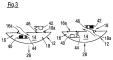
- Fig. 3 shows a schematic representation of the inlet diaphragm valve 16 and the outlet diaphragm valve 18 of a further exemplary embodiment of a vacuum device according to the invention in the suction or compression phase.
- the inlet and outlet diaphragm valves 16, 18 are acted upon by associated exciters 40, 42 respectively only to support their opening movement, wherein the opening movement supported by the application takes place against a restoring force.
- the opening movement of the diaphragm valves 16, 18, which is assisted by the application can take place, in particular, against a closing force biasing the diaphragm valve 16, 18 into its closed position, which is preferably provided mechanically and in particular by the membrane inherent tension or by means of a spring device 44, 46.
- the diaphragm valves 16, 18 can be acted upon by the exciters 40, 42 again magnetically, electromagnetically, electrically or electrostatically.
- the pathogens 40, 42 it may in particular be again electrodes or electromagnets.
- the pathogens can in particular again in the head section or head cover 22 (see, for example Fig. 1 ) of the relevant vacuum device 10 may be arranged.
- At least one of the membrane valves 16, 18 may again comprise a magnetic and / or magnetizable valve membrane 16a, 18a or a valve membrane 16a, 18a which comprises a material or consists of a material which is doped with magnetic and / or magnetizable particles, which comprises a material or consists of a material which is or contains fluororubber, and / or which comprises a material or consists of a material which is or contains an electro- or magnetorheological elastomer or a dielectric elastomer.
- the vacuum device can be designed, for example, as a vacuum pump 10, in particular a membrane vacuum pump or as a piston vacuum pump, which has a pump chamber 12 or a piston and a pumping chamber 14 and at least one inlet diaphragm valve 16 and at least one outlet diaphragm valve 18 via which a medium sucked into the suction chamber 14 in a suction phase and ejected in a compression phase from the pump chamber 14, wherein the opening movement and / or the closing movement of the inlet diaphragm valve 16 and / or the outlet diaphragm valve 18 can be assisted by its application.
- a vacuum pump 10 in particular a membrane vacuum pump or as a piston vacuum pump
- a pump chamber 12 or a piston and a pumping chamber 14 and at least one inlet diaphragm valve 16 and at least one outlet diaphragm valve 18 via which a medium sucked into the suction chamber 14 in a suction phase and ejected in a compression phase from the pump chamber 14, wherein the
Landscapes
- Engineering & Computer Science (AREA)
- Mechanical Engineering (AREA)
- General Engineering & Computer Science (AREA)
- Reciprocating Pumps (AREA)
Abstract
Description
- Die vorliegende Erfindung betrifft eine Vakuumeinrichtung, insbesondere Vakuumpumpe, mit wenigstens einem Membranventil, über das ein Medium in einer Saugphase eingesaugt und/oder in einer Kompressionsphase ausgestoßen wird. Die Erfindung betrifft ferner ein Verfahren zum Betreiben einer solchen Vakuumeinrichtung.
- Bei den bisher bekannten Vakuumeinrichtungen dieser Art besteht das Problem, dass unter bestimmten Bedingungen der vorhandene Druck nicht mehr ausreicht, um die Membranventile zu öffnen. So wird dadurch beispielsweise bei einer Membranpumpe der maximale Enddruck auf etwa 10 mbar begrenzt.
- Der Erfindung liegt somit die Aufgabe zugrunde, eine Vakuumeinrichtung sowie ein Verfahren der eingangs genannten Art anzugeben, bei denen unabhängig vom jeweiligen Druck stets ein zuverlässiges Öffnen der Membranventile gewährleistet ist.
- Gemäß einem ersten Aspekt der Erfindung wird diese Aufgabe bezüglich der Vakuumeinrichtung dadurch gelöst, dass das Membranventil zur Unterstützung einer Öffnungs- und/oder Schließbewegung magnetisch oder elektromagnetisch beaufschlagbar ist.
- Gemäß einem weiteren Aspekt der Erfindung wird die Aufgabe bezüglich der Vakuumeinrichtung dadurch gelöst, dass das Membranventil zur Unterstützung seiner Öffnungs- und/oder Schließbewegung elektrisch oder elektrostatisch beaufschlagbar ist.
- Aufgrund dieser Lösungen ist auf einfache Weise unabhängig vom jeweiligen Druck stets ein zuverlässiges Öffnen der Membranventile gewährleistet. Mit der erfindungsgemäßen magnetischen, elektromagnetischen, elektrischen und/oder elektrostatischen Unterstützung der Öffnungsbewegungen der Membranventile und dem damit einhergehenden verbesserten Öffnungsverhalten der Membranventile wird beispielsweise bei einer Membranpumpe ein tieferer Enddruck erreicht.
- Das Membranventil ist bevorzugt zeitlich abgestimmt auf den Betrieb der Vakuumeinrichtung, insbesondere synchron mit der Beaufschlagung eines Schöpfraums der als Vakuumpumpe ausgebildeten Vakuumeinrichtung, beaufschlagbar. Durch eine solche zeitliche Abstimmung kann beispielsweise bei einer Vakuumpumpe also sichergestellt werden, dass die Unterstützung der Öffnungsbewegung eines Einlassventils mit der Saugphase und die Öffnungsbewegung eines Auslassventils mit der Kompressionsphase synchronisiert wird.
- Bevorzugt ist sowohl die Öffnungsbewegung als auch die Schließbewegung des Membranventils durch die Beaufschlagung unterstützbar.
- Grundsätzlich sind jedoch auch solche Ausführungen der erfindungsgemäßen Vakuumeinrichtung denkbar, bei der ausschließlich die Öffnungsbewegung des Membranventils durch die Beaufschlagung unterstützbar ist.
- Gemäß einer bevorzugten praktischen Ausführungsform der erfindungsgemäßen Vakuumeinrichtung erfolgt die durch die Beaufschlagung unterstützte Öffnungsbewegung des Membranventils gegen eine Rückstellkraft, insbesondere gegen eine das Membranventil in dessen geschlossene Stellung vorspannende Schließkraft, die bevorzugt mechanisch und insbesondere durch die Membraneigenspannung oder mittels einer Federeinrichtung bereitgestellt ist. In einem solchen Fall erfolgt das Schließen der Membranventile durch die betreffende Rückstellkraft. Eine zusätzliche Unterstützung der Schließbewegung ist hier nicht erforderlich.
- Zur Beaufschlagung des Membranventils ist bevorzugt wenigstens ein elektrisch beaufschlagbarer Erreger, insbesondere eine Elektrode oder ein Elektromagnet vorgesehen. Ein solcher Erreger ist zweckmäßigerweise in einem Kopfabschnitt der Vakuumeinrichtung angeordnet.
- Bevorzugt umfasst das Membranventil eine magnetische und/oder magnetisierbare Ventilmembran.
- Gemäß einer bevorzugten praktischen Ausführungsform der erfindungsgemäßen Vakuumeinrichtung weist das Membranventil eine Ventilmembran auf, die ein Material umfasst oder aus einem Material besteht, das mit magnetischen und/oder magnetisierbaren Partikeln dotiert ist.
- Das Membranventil kann insbesondere auch eine Ventilmembran aufweisen, die ein Material umfasst oder aus einem Material besteht, das Fluorkautschuk ist oder enthält.
- Gemäß einer weiteren vorteilhaften Ausführungsform der erfindungsgemäßen Vakuumeinrichtung weist das Membranventil eine Ventilmembran auf, die ein Material umfasst oder aus einem Material besteht, das ein elektro- oder magnetorheologisches Elastomer oder ein dielektrisches Elastomer ist oder enthält.
- Die Vakuumeinrichtung kann beispielsweise als Vakuumpumpe ausgebildet sein, insbesondere als Membranvakuumpumpe oder als Kolbenvakuumpumpe, wobei die Vakuumpumpe einen insbesondere über eine Pumpenmembran oder einen Kolben beaufschlagbaren Schöpfraum und wenigstens ein Einlassmembranventil sowie wenigstens ein Auslassmembranventil aufweist, über die ein Medium in einer Saugphase in den Schöpfraum gesaugt und in einer Kompressionsphase aus dem Schöpfraum ausgestoßen wird, und wobei die Öffnungsbewegung und/oder die Schließbewegung des Einlassmembranventils und/oder des Auslassmembranventils durch dessen Beaufschlagung unterstützbar ist.
- Das erfindungsgemäße Verfahren zum Betreiben einer Vakuumeinrichtung, insbesondere einer Vakuumpumpe, die wenigstens ein Membranventil aufweist, über das ein Medium in einer Saugphase eingesaugt und/oder in einer Kompressionsphase ausgestoßen wird, zeichnet sich dadurch aus, dass das Membranventil zur Unterstützung seiner Öffnungs- und/oder Schließbewegung magnetisch, elektromagnetisch, elektrisch und/oder elektrostatisch beaufschlagt wird.
- Dabei erfolgt die Beaufschlagung des Einlassmembranventils und/oder des Auslassmembranventils bevorzugt zeitlich abgestimmt auf den Betrieb der Vakuumeinrichtung, insbesondere synchron mit der Beaufschlagung eines Schöpfraums der als Vakuumpumpe ausgebildeten Vakuumeinrichtung.
- Die Erfindung wird im Folgenden anhand von Ausführungsbeispielen unter Bezugnahme auf die Zeichnung näher beschrieben; in dieser zeigen:
- Fig. 1
- eine schematische Darstellung einer Membranpumpe als Beispiel einer Vakuumeinrichtung, in der erfindungsgemäße Membranventile einsetzbar sind,
- Fig. 2
- eine schematische Darstellung der Einlass- und Auslassmembranventile einer beispielhaften Ausführungsform einer erfindungsgemäßen Vakuumeinrichtung in der Saug- bzw. Kompressionsphase, und
- Fig. 3
- eine schematische Darstellung der Einlass- und Auslassmembranventile einer weiteren beispielhaften Ausführungsform einer erfindungsgemäßen Vakuumeinrichtung in der Saug- bzw. Kompressionsphase.
-
Fig. 1 zeigt in schematischer Darstellung eine Membranpumpe 10 als Beispiel einer Vakuumeinrichtung, in der erfindungsgemäße Membranventile einsetzbar sind. - Die Membranpumpe 10 umfasst einen über eine Pumpenmembran 12 beaufschlagbaren Schöpfraum 14 sowie ein Einlass- und ein Auslassventil, die durch ein erfindungsgemäßes Einlassmembranventil 16 bzw. ein erfindungsgemäßes Auslassmembranventil 18 gebildet sein können, wie sie weiter unten näher beschrieben werden und zur Unterstützung deren Öffnungs- und/oder Schließbewegung entsprechend magnetisch, elektromagnetisch, elektrisch oder elektrostatisch beaufschlagbar sind.
- Über die Membranventile 16, 18 wird ein Medium wie insbesondere Gas in einer Saugphase in den Schöpfraum 14 gesaugt und in einer Kompressionsphase aus dem Schöpfraum 14 ausgestoßen.
- Die Membranpumpe 10 umfasst ein Gehäuse 20 sowie einen Kopfabschnitt oder Kopfdeckel 22, zwischen denen die Pumpenmembran 12 eingespannt ist.
- Der Schöpfraum 14 wird vom Kopfabschnitt bzw. Kopfdeckel 22 und der Pumpenmembran 12 begrenzt, die beispielsweise über einen von einer Kurbelwelle angetriebenen Pleuel 24 bewegt wird.
-
Fig. 2 zeigt in schematischer Darstellung das Einlassmembranventil 16 und das Auslassmembranventil 18 einer beispielhaften Ausführungsform einer erfindungsgemäßen Vakuumeinrichtung in der Saug- bzw. Kompressionsphase, bei der das Einlassmembranventil 16 und das Auslassmembranventil 18 jeweils sowohl zur Unterstützung deren Öffnungsbewegung als auch zur Unterstützung deren Schließbewegung magnetisch, elektromagnetisch, elektrisch oder elektrostatisch beaufschlagbar sind. Dabei ist den Membranventilen 16, 18 zur entsprechenden Beaufschlagung jeweils ein Erreger 30 bzw. 32 zugeordnet, bei denen es sich insbesondere jeweils um einen Elektromagneten oder eine Elektrode handeln kann. - In den Fällen, in denen die Vakuumeinrichtung beispielsweise eine Membranpumpe 10 (vgl.
Fig. 1 ) umfasst, können das Einlassmembranventil 16 und das Auslassmembranventil 18 insbesondere im Kopfabschnitt bzw. Kopfdeckel 22 der betreffenden Membranpumpe 10 angeordnet sein. - In der Saugphase wird die Pumpenmembran 12 in Saugrichtung 26 von den Membranventilen 16, 18 weg bewegt. Dagegen wird die Pumpenmembran 12 in der Kompressionsphase in Kompressionsrichtung 28 zu den Membranventilen 16 hin bewegt.
- Die Membranventile 16, 18 können zeitlich abgestimmt auf den Betrieb der Vakuumeinrichtung und insbesondere synchron mit der Beaufschlagung eines Schöpfraums 14 einer als Vakuumpumpe 10 (vgl.
Fig. 1 ) ausgebildeten Vakuumeinrichtung beaufschlagbar sein. Die Beaufschlagung kann somit synchron zur Beaufschlagung des Schöpfraums 14 über die Pumpenmembran 12 erfolgen und gegebenenfalls im Pumprhythmus der betreffenden Vakuumpumpe 10 variieren. - Die Membranventile 16, 18 können beispielsweise auch eine Ventilmembran 16a bzw. 18a aufweisen, die magnetisch und/oder magnetisierbar ist, die ein Material umfasst oder aus einem Material besteht, das mit magnetischen und/oder magnetisierbaren Partikeln dotiert ist, die ein Material umfasst oder aus einem Material besteht, das Fluorkautschuk ist oder enthält, oder die ein Material umfasst oder aus einem Material besteht, das ein elektro- oder magnetorheologisches Elastomer oder ein dielektrisches Elastomer ist oder enthält.
- Grundsätzlich sind auch solche Ausführungen denkbar, bei denen ausschließlich die Öffnungsbewegung eines jeweiligen Membranventils 16, 18 durch die Beaufschlagung unterstützbar ist.
-
Fig. 3 zeigt in schematischer Darstellung das Einlassmembranventil 16 sowie das Auslassmembranventil 18 einer weiteren beispielhaften Ausführungsform einer erfindungsgemäßen Vakuumeinrichtung in der Saug- bzw. Kompressionsphase. Im vorliegenden Fall sind die Einlass- und Auslassmembranventile 16, 18 über zugeordnete Erreger 40, 42 jeweils nur zur Unterstützung deren Öffnungsbewegung beaufschlagbar, wobei die durch die Beaufschlagung unterstützte Öffnungsbewegung gegen eine Rückstellkraft erfolgt. Dabei kann die durch die Beaufschlagung unterstützte Öffnungsbewegung der Membranventile 16, 18 insbesondere jeweils gegen eine das Membranventil 16, 18 in dessen geschlossene Stellung vorspannende Schließkraft erfolgen, die bevorzugt mechanisch und insbesondere durch die Membraneigenspannung oder mittels einer Federeinrichtung 44, 46 bereitgestellt ist. - Auch im vorliegenden Fall können die Membranventile 16, 18 durch die Erreger 40, 42 wieder magnetisch, elektromagnetisch, elektrisch oder elektrostatisch beaufschlagbar sein. Bei den Erregern 40, 42 kann es sich entsprechend insbesondere wieder um Elektroden oder Elektromagnete handeln. Die Erreger können insbesondere wieder im Kopfabschnitt bzw. Kopfdeckel 22 (vgl. zum Beispiel
Fig. 1 ) der betreffenden Vakuumeinrichtung 10 angeordnet sein. - Zumindest eines der Membranventile 16, 18 kann beispielsweise auch wieder eine magnetische und/oder magnetisierbare Ventilmembran 16a, 18a oder eine Ventilmembran 16a, 18a aufweisen, die ein Material umfasst oder aus einem Material besteht, das mit magnetischen und/oder magnetisierbaren Partikeln dotiert ist, die ein Material umfasst oder aus einem Material besteht, das Fluorkautschuk ist oder enthält, und/oder die ein Material umfasst oder aus einem Material besteht, das ein elektro- oder magnetorheologisches Elastomer oder ein dielektrisches Elastomer ist oder enthält.
- Im Übrigen kann diese in der
Fig. 3 dargestellte Vakuumeinrichtung zumindest im Wesentlichen wieder den gleichen Aufbau besitzen wie die in derFig. 2 dargestellte Ausführungsform, wobei einander entsprechenden Teilen gleiche Bezugszeichen zugeordnet sind. - Wie bereits erwähnt, kann die erfindungsgemäße Vakuumeinrichtung beispielsweise als Vakuumpumpe 10, insbesondere Membranvakuumpumpe oder als Kolbenvakuumpumpe ausgebildet sein, die einen insbesondere über eine Pumpenmembran 12 oder einen Kolben beaufschlagbaren Schöpfraum 14 und wenigstens ein Einlassmembranventil 16 sowie wenigstens ein Auslassmembranventil 18 aufweist, über die ein Medium in einer Saugphase in den Schöpfraum 14 gesaugt und in einer Kompressionsphase aus dem Schöpfraum 14 ausgestoßen wird, wobei die Öffnungsbewegung und/oder die Schließbewegung des Einlassmembranventils 16 und/oder des Auslassmembranventils 18 durch dessen Beaufschlagung unterstützbar ist.
-
- 10
- Vakuumeinrichtung, Membranpumpe
- 12
- Pumpenmembran
- 14
- Schöpfraum
- 16
- Einlassmembranventil
- 16a
- Ventilmembran
- 18
- Auslassmembranventil
- 18a
- Ventilmembran
- 20
- Gehäuse
- 22
- Kopfabschnitt, Kopfdeckel
- 24
- Pleuel
- 26
- Saugrichtung
- 28
- Kompressionsrichtung
- 30
- Erreger
- 32
- Erreger
- 40
- Erreger
- 42
- Erreger
- 44
- Feder
- 46
- Feder
Claims (15)
- Vakuumeinrichtung, insbesondere Vakuumpumpe (10), mit wenigstens einem Membranventil (16, 18), über das ein Medium in einer Saugphase eingesaugt und/oder in einer Kompressionsphase ausgestoßen wird, dadurch gekennzeichnet, dass das Membranventil (16, 18) zur Unterstützung seiner Öffnungs- und/oder Schließbewegung magnetisch oder elektromagnetisch beaufschlagbar ist.
- Vakuumeinrichtung, insbesondere Vakuumpumpe (10), mit wenigstens einem Membranventil (16, 18), über das ein Medium in einer Saugphase eingesaugt und/oder in einer Kompressionsphase ausgestoßen wird, dadurch gekennzeichnet, dass das Membranventil (16, 18) zur Unterstützung seiner Öffnungs- und/oder Schließbewegung elektrisch oder elektrostatisch beaufschlagbar ist.
- Vakuumeinrichtung nach Anspruch 1 oder 2,
dadurch gekennzeichnet, dass das Membranventil (16, 18) zeitlich abgestimmt auf den Betrieb der Vakuumeinrichtung, insbesondere synchron mit der Beaufschlagung eines Schöpfraums (14) der als Vakuumpumpe (10) ausgebildeten Vakuumeinrichtung, beaufschlagbar ist. - Vakuumeinrichtung nach einem der vorstehenden Ansprüche,
dadurch gekennzeichnet, dass sowohl die Öffnungsbewegung als auch die Schließbewegung des Membranventils (16, 18) durch die Beaufschlagung unterstützbar ist. - Vakuumeinrichtung nach einem der Ansprüche 1 bis 3,
dadurch gekennzeichnet, dass ausschließlich die Öffnungsbewegung des Membranventils (16, 18) durch die Beaufschlagung unterstützbar ist. - Vakuumeinrichtung nach einem der vorstehenden Ansprüche,
dadurch gekennzeichnet, dass die durch die Beaufschlagung unterstützte Öffnungsbewegung des Membranventils (16, 18) gegen eine Rückstellkraft erfolgt, insbesondere gegen eine das Membranventil (16, 18) in dessen geschlossene Stellung vorspannende Schließkraft, die bevorzugt mechanisch und insbesondere durch die Membraneigenspannung oder mittels einer Federeinrichtung (44, 46) bereitgestellt ist. - Vakuumeinrichtung nach einem der vorstehenden Ansprüche,
dadurch gekennzeichnet, dass zur Beaufschlagung des Membranventils (16, 18) wenigstens ein elektrisch beaufschlagbarer Erreger (30, 32, 40, 42), insbesondere eine Elektrode oder ein Elektromagnet, vorgesehen ist. - Vakuumeinrichtung nach Anspruch 7,
dadurch gekennzeichnet, dass der Erreger (30, 32) in einem Kopfabschnitt (22) der Vakuumeinrichtung (10) angeordnet ist. - Vakuumeinrichtung nach einem der vorstehenden Ansprüche,
dadurch gekennzeichnet, dass das Membranventil (16, 18) eine magnetische und/oder magnetisierbare Ventilmembran (16a, 18a) aufweist. - Vakuumeinrichtung nach einem der vorstehenden Ansprüche,
dadurch gekennzeichnet, dass das Membranventil (16, 18) eine Ventilmembran (16a, 18a) aufweist, die ein Material umfasst oder aus einem Material besteht, das mit magnetischen und/oder magnetisierbaren Partikeln dotiert ist. - Vakuumeinrichtung nach einem der vorstehenden Ansprüche,
dadurch gekennzeichnet, dass das Membranventil (16, 18) eine Ventilmembran (16a, 18a) aufweist, die ein Material umfasst oder aus einem Material besteht, das Fluorkautschuk ist oder enthält. - Vakuumeinrichtung nach einem der vorstehenden Ansprüche,
dadurch gekennzeichnet, dass das Membranventil (16, 18) eine Ventilmembran (16a, 18a) aufweist, die ein Material umfasst oder aus einem Material besteht, das ein elektro- oder magnetorheologisches Elastomer oder ein dielektrisches Elastomer ist oder enthält. - Vakuumeinrichtung nach einem der vorstehenden Ansprüche,
dadurch gekennzeichnet, dass die Vakuumeinrichtung als Vakuumpumpe (10) ausgebildet ist, insbesondere als Membranvakuumpumpe oder als Kolbenvakuumpumpe, wobei die Vakuumpumpe (10) einen, insbesondere über eine Pumpenmembran (12) oder einen Kolben, beaufschlagbaren Schöpfraum (14) und wenigstens ein Einlassmembranventil (16) sowie wenigstens ein Auslassmembranventil (18) aufweist, über die ein Medium in einer Saugphase in den Schöpfraum (14) gesaugt und in einer Kompressionsphase aus dem Schöpfraum (14) ausgestoßen wird, und wobei die Öffnungsbewegung und/oder die Schließbewegung des Einlassmembranventils (16) und/oder des Auslassmembranventils (18) durch dessen Beaufschlagung unterstützbar ist. - Verfahren zum Betreiben einer Vakuumeinrichtung, insbesondere einer Vakuumpumpe (10), die wenigstens ein Membranventil (16, 18) aufweist, über das ein Medium in einer Saugphase eingesaugt und/oder in einer Kompressionsphase ausgestoßen wird,
dadurch gekennzeichnet, dass das Membranventil (16, 18) zur Unterstützung seiner Öffnungs- und/oder Schließbewegung magnetisch, elektromagnetisch, elektrisch oder elektrostatisch beaufschlagt wird. - Verfahren nach Anspruch 14,
dadurch gekennzeichnet, dass die Beaufschlagung des Einlassmembranventils (16) und/oder des Auslassmembranventils (18) zeitlich abgestimmt auf den Betrieb der Vakuumeinrichtung, insbesondere synchron mit der Beaufschlagung eines Schöpfraums (14) der als Vakuumpumpe (10) ausgebildeten Vakuumeinrichtung, erfolgt.
Applications Claiming Priority (1)
| Application Number | Priority Date | Filing Date | Title |
|---|---|---|---|
| DE102014117793.2A DE102014117793A1 (de) | 2014-12-03 | 2014-12-03 | Vakuumeinrichtung |
Publications (2)
| Publication Number | Publication Date |
|---|---|
| EP3029324A1 true EP3029324A1 (de) | 2016-06-08 |
| EP3029324B1 EP3029324B1 (de) | 2017-10-04 |
Family
ID=54771018
Family Applications (1)
| Application Number | Title | Priority Date | Filing Date |
|---|---|---|---|
| EP15197560.4A Active EP3029324B1 (de) | 2014-12-03 | 2015-12-02 | Vakuumeinrichtung |
Country Status (2)
| Country | Link |
|---|---|
| EP (1) | EP3029324B1 (de) |
| DE (1) | DE102014117793A1 (de) |
Cited By (1)
| Publication number | Priority date | Publication date | Assignee | Title |
|---|---|---|---|---|
| CN112302845A (zh) * | 2019-07-24 | 2021-02-02 | 现代自动车株式会社 | 用于车辆的燃料供应系统的网状过滤器 |
Families Citing this family (1)
| Publication number | Priority date | Publication date | Assignee | Title |
|---|---|---|---|---|
| WO2023018633A1 (en) * | 2021-08-09 | 2023-02-16 | Sartorius Stedim Fmt Sas | Actuated elastic valves |
Citations (8)
| Publication number | Priority date | Publication date | Assignee | Title |
|---|---|---|---|---|
| DE4244619A1 (de) * | 1992-12-31 | 1994-07-07 | Knf Neuberger Gmbh | Verfahren zum Betreiben einer Membranpumpe sowie Membranpumpe zum Durchführen des Verfahrens |
| WO2003006826A2 (en) * | 2001-07-13 | 2003-01-23 | Delaware Capital Formation, Inc. | Elastomeric sealing element for gas compressor valve |
| US20040265150A1 (en) * | 2003-05-30 | 2004-12-30 | The Regents Of The University Of California | Magnetic membrane system |
| US20060147329A1 (en) * | 2004-12-30 | 2006-07-06 | Tanner Edward T | Active valve and active valving for pump |
| EP2113660A1 (de) * | 2008-04-30 | 2009-11-04 | Ricoh Company, Ltd. | Luftabgabevorrichtung und Bildgebungsvorrichtung |
| DE102008033153A1 (de) * | 2008-07-15 | 2010-01-21 | Siemens Aktiengesellschaft | Membranpumpe und Verfahren zu deren Betrieb |
| EP2354546A1 (de) * | 2010-02-09 | 2011-08-10 | Vacuubrand Gmbh + Co Kg | Membranvakuumpumpe |
| WO2013017143A1 (en) * | 2011-08-04 | 2013-02-07 | L&P Swiss Holding Ag | Diaphragm pump for a seat adjusting device and seat adjusting device |
-
2014
- 2014-12-03 DE DE102014117793.2A patent/DE102014117793A1/de not_active Withdrawn
-
2015
- 2015-12-02 EP EP15197560.4A patent/EP3029324B1/de active Active
Patent Citations (8)
| Publication number | Priority date | Publication date | Assignee | Title |
|---|---|---|---|---|
| DE4244619A1 (de) * | 1992-12-31 | 1994-07-07 | Knf Neuberger Gmbh | Verfahren zum Betreiben einer Membranpumpe sowie Membranpumpe zum Durchführen des Verfahrens |
| WO2003006826A2 (en) * | 2001-07-13 | 2003-01-23 | Delaware Capital Formation, Inc. | Elastomeric sealing element for gas compressor valve |
| US20040265150A1 (en) * | 2003-05-30 | 2004-12-30 | The Regents Of The University Of California | Magnetic membrane system |
| US20060147329A1 (en) * | 2004-12-30 | 2006-07-06 | Tanner Edward T | Active valve and active valving for pump |
| EP2113660A1 (de) * | 2008-04-30 | 2009-11-04 | Ricoh Company, Ltd. | Luftabgabevorrichtung und Bildgebungsvorrichtung |
| DE102008033153A1 (de) * | 2008-07-15 | 2010-01-21 | Siemens Aktiengesellschaft | Membranpumpe und Verfahren zu deren Betrieb |
| EP2354546A1 (de) * | 2010-02-09 | 2011-08-10 | Vacuubrand Gmbh + Co Kg | Membranvakuumpumpe |
| WO2013017143A1 (en) * | 2011-08-04 | 2013-02-07 | L&P Swiss Holding Ag | Diaphragm pump for a seat adjusting device and seat adjusting device |
Cited By (2)
| Publication number | Priority date | Publication date | Assignee | Title |
|---|---|---|---|---|
| CN112302845A (zh) * | 2019-07-24 | 2021-02-02 | 现代自动车株式会社 | 用于车辆的燃料供应系统的网状过滤器 |
| US12220653B2 (en) | 2019-07-24 | 2025-02-11 | Hyundai Motor Company | Mesh filter for fuel supply system of vehicle |
Also Published As
| Publication number | Publication date |
|---|---|
| EP3029324B1 (de) | 2017-10-04 |
| DE102014117793A1 (de) | 2016-06-09 |
Similar Documents
| Publication | Publication Date | Title |
|---|---|---|
| DE69502906T2 (de) | Pumpe mit Verwendung von Formgedächtnislegierungen | |
| DE112017000240T5 (de) | Überdruckentlastungssystem für fluidaustrittsseite | |
| DE102013218713A1 (de) | Hochdruckpumpe für ein Kraftstoffeinspritzsystem, Kraftstoffeinspritzsystem | |
| DE102008033411A1 (de) | Rückschlagventil | |
| DE102011075269A1 (de) | Verfahren und Vorrichtung zum Steuern eines Ventils | |
| DE102016115281A1 (de) | Pumpe | |
| EP2977741A1 (de) | Vorrichtung zur entnahme einer probe und zur zuführung in ein analytisches auswertesystem | |
| DE102013015453A1 (de) | Hubkolbenpumpe mit zwei Förderrichtungen | |
| DE102013208707A1 (de) | Überstromventil für eine Hochdruckpumpe in einem Kraftstoffeinspritzsystem | |
| DE102008041383A1 (de) | Steckpumpe | |
| DE102014117793A1 (de) | Vakuumeinrichtung | |
| DE102014200695A1 (de) | Hochdruckpumpe mit einem elektromagnetischen Saugventil | |
| DE602004008596T2 (de) | Schwingankerpumpe | |
| DE10309541B4 (de) | Kolbenverdichter | |
| DE102017200238A1 (de) | Verfahren zum Ermitteln einer Ungleichförderung bei einer Hochdruckpumpe | |
| DE102017001317B3 (de) | Hubkolbenpumpe mit aktivem Dämpfer und Verfahren zum Betrieb der Hubkolbenpumpe | |
| DE102014200584A1 (de) | Elektromagnetisch ansteuerbares Saugventil | |
| DE102017113724A1 (de) | Fluidbewegungsvorrichtung | |
| DE102016007638A1 (de) | Vorrichtung zum Auftragen eines viskosen Materials | |
| DE102009000965A1 (de) | Hochdruckkraftstoffpumpe mit intergriertem Hochdruckspeicher | |
| DE102014119566A1 (de) | Pumpsystem für gasförmige und flüssige Medien | |
| DE102013219396A1 (de) | Verfahren zum Erkennen eines unerwünschten Schließens eines elektrischen Saugventils einer Hochdruckpumpe | |
| DE10352024A1 (de) | Elektromagnetventil | |
| EP3601800B1 (de) | Mehrstufiger verdichter | |
| EP2496824A1 (de) | Steuerventilanordnung |
Legal Events
| Date | Code | Title | Description |
|---|---|---|---|
| PUAI | Public reference made under article 153(3) epc to a published international application that has entered the european phase |
Free format text: ORIGINAL CODE: 0009012 |
|
| AK | Designated contracting states |
Kind code of ref document: A1 Designated state(s): AL AT BE BG CH CY CZ DE DK EE ES FI FR GB GR HR HU IE IS IT LI LT LU LV MC MK MT NL NO PL PT RO RS SE SI SK SM TR |
|
| AX | Request for extension of the european patent |
Extension state: BA ME |
|
| STAA | Information on the status of an ep patent application or granted ep patent |
Free format text: STATUS: REQUEST FOR EXAMINATION WAS MADE |
|
| 17P | Request for examination filed |
Effective date: 20161208 |
|
| RBV | Designated contracting states (corrected) |
Designated state(s): AL AT BE BG CH CY CZ DE DK EE ES FI FR GB GR HR HU IE IS IT LI LT LU LV MC MK MT NL NO PL PT RO RS SE SI SK SM TR |
|
| GRAP | Despatch of communication of intention to grant a patent |
Free format text: ORIGINAL CODE: EPIDOSNIGR1 |
|
| STAA | Information on the status of an ep patent application or granted ep patent |
Free format text: STATUS: GRANT OF PATENT IS INTENDED |
|
| INTG | Intention to grant announced |
Effective date: 20170331 |
|
| GRAS | Grant fee paid |
Free format text: ORIGINAL CODE: EPIDOSNIGR3 |
|
| GRAA | (expected) grant |
Free format text: ORIGINAL CODE: 0009210 |
|
| STAA | Information on the status of an ep patent application or granted ep patent |
Free format text: STATUS: THE PATENT HAS BEEN GRANTED |
|
| AK | Designated contracting states |
Kind code of ref document: B1 Designated state(s): AL AT BE BG CH CY CZ DE DK EE ES FI FR GB GR HR HU IE IS IT LI LT LU LV MC MK MT NL NO PL PT RO RS SE SI SK SM TR |
|
| REG | Reference to a national code |
Ref country code: GB Ref legal event code: FG4D Free format text: NOT ENGLISH |
|
| REG | Reference to a national code |
Ref country code: CH Ref legal event code: EP |
|
| REG | Reference to a national code |
Ref country code: AT Ref legal event code: REF Ref document number: 934312 Country of ref document: AT Kind code of ref document: T Effective date: 20171015 |
|
| REG | Reference to a national code |
Ref country code: IE Ref legal event code: FG4D Free format text: LANGUAGE OF EP DOCUMENT: GERMAN |
|
| REG | Reference to a national code |
Ref country code: DE Ref legal event code: R096 Ref document number: 502015002009 Country of ref document: DE |
|
| REG | Reference to a national code |
Ref country code: FR Ref legal event code: PLFP Year of fee payment: 3 |
|
| REG | Reference to a national code |
Ref country code: NL Ref legal event code: MP Effective date: 20171004 |
|
| REG | Reference to a national code |
Ref country code: LT Ref legal event code: MG4D |
|
| PG25 | Lapsed in a contracting state [announced via postgrant information from national office to epo] |
Ref country code: NL Free format text: LAPSE BECAUSE OF FAILURE TO SUBMIT A TRANSLATION OF THE DESCRIPTION OR TO PAY THE FEE WITHIN THE PRESCRIBED TIME-LIMIT Effective date: 20171004 |
|
| PG25 | Lapsed in a contracting state [announced via postgrant information from national office to epo] |
Ref country code: LT Free format text: LAPSE BECAUSE OF FAILURE TO SUBMIT A TRANSLATION OF THE DESCRIPTION OR TO PAY THE FEE WITHIN THE PRESCRIBED TIME-LIMIT Effective date: 20171004 Ref country code: FI Free format text: LAPSE BECAUSE OF FAILURE TO SUBMIT A TRANSLATION OF THE DESCRIPTION OR TO PAY THE FEE WITHIN THE PRESCRIBED TIME-LIMIT Effective date: 20171004 Ref country code: SE Free format text: LAPSE BECAUSE OF FAILURE TO SUBMIT A TRANSLATION OF THE DESCRIPTION OR TO PAY THE FEE WITHIN THE PRESCRIBED TIME-LIMIT Effective date: 20171004 Ref country code: ES Free format text: LAPSE BECAUSE OF FAILURE TO SUBMIT A TRANSLATION OF THE DESCRIPTION OR TO PAY THE FEE WITHIN THE PRESCRIBED TIME-LIMIT Effective date: 20171004 Ref country code: NO Free format text: LAPSE BECAUSE OF FAILURE TO SUBMIT A TRANSLATION OF THE DESCRIPTION OR TO PAY THE FEE WITHIN THE PRESCRIBED TIME-LIMIT Effective date: 20180104 |
|
| PG25 | Lapsed in a contracting state [announced via postgrant information from national office to epo] |
Ref country code: HR Free format text: LAPSE BECAUSE OF FAILURE TO SUBMIT A TRANSLATION OF THE DESCRIPTION OR TO PAY THE FEE WITHIN THE PRESCRIBED TIME-LIMIT Effective date: 20171004 Ref country code: IS Free format text: LAPSE BECAUSE OF FAILURE TO SUBMIT A TRANSLATION OF THE DESCRIPTION OR TO PAY THE FEE WITHIN THE PRESCRIBED TIME-LIMIT Effective date: 20180204 Ref country code: LV Free format text: LAPSE BECAUSE OF FAILURE TO SUBMIT A TRANSLATION OF THE DESCRIPTION OR TO PAY THE FEE WITHIN THE PRESCRIBED TIME-LIMIT Effective date: 20171004 Ref country code: GR Free format text: LAPSE BECAUSE OF FAILURE TO SUBMIT A TRANSLATION OF THE DESCRIPTION OR TO PAY THE FEE WITHIN THE PRESCRIBED TIME-LIMIT Effective date: 20180105 Ref country code: RS Free format text: LAPSE BECAUSE OF FAILURE TO SUBMIT A TRANSLATION OF THE DESCRIPTION OR TO PAY THE FEE WITHIN THE PRESCRIBED TIME-LIMIT Effective date: 20171004 Ref country code: BG Free format text: LAPSE BECAUSE OF FAILURE TO SUBMIT A TRANSLATION OF THE DESCRIPTION OR TO PAY THE FEE WITHIN THE PRESCRIBED TIME-LIMIT Effective date: 20180104 |
|
| REG | Reference to a national code |
Ref country code: DE Ref legal event code: R097 Ref document number: 502015002009 Country of ref document: DE |
|
| PG25 | Lapsed in a contracting state [announced via postgrant information from national office to epo] |
Ref country code: SK Free format text: LAPSE BECAUSE OF FAILURE TO SUBMIT A TRANSLATION OF THE DESCRIPTION OR TO PAY THE FEE WITHIN THE PRESCRIBED TIME-LIMIT Effective date: 20171004 Ref country code: EE Free format text: LAPSE BECAUSE OF FAILURE TO SUBMIT A TRANSLATION OF THE DESCRIPTION OR TO PAY THE FEE WITHIN THE PRESCRIBED TIME-LIMIT Effective date: 20171004 Ref country code: DK Free format text: LAPSE BECAUSE OF FAILURE TO SUBMIT A TRANSLATION OF THE DESCRIPTION OR TO PAY THE FEE WITHIN THE PRESCRIBED TIME-LIMIT Effective date: 20171004 |
|
| PLBE | No opposition filed within time limit |
Free format text: ORIGINAL CODE: 0009261 |
|
| STAA | Information on the status of an ep patent application or granted ep patent |
Free format text: STATUS: NO OPPOSITION FILED WITHIN TIME LIMIT |
|
| PG25 | Lapsed in a contracting state [announced via postgrant information from national office to epo] |
Ref country code: RO Free format text: LAPSE BECAUSE OF FAILURE TO SUBMIT A TRANSLATION OF THE DESCRIPTION OR TO PAY THE FEE WITHIN THE PRESCRIBED TIME-LIMIT Effective date: 20171004 Ref country code: PL Free format text: LAPSE BECAUSE OF FAILURE TO SUBMIT A TRANSLATION OF THE DESCRIPTION OR TO PAY THE FEE WITHIN THE PRESCRIBED TIME-LIMIT Effective date: 20171004 Ref country code: SM Free format text: LAPSE BECAUSE OF FAILURE TO SUBMIT A TRANSLATION OF THE DESCRIPTION OR TO PAY THE FEE WITHIN THE PRESCRIBED TIME-LIMIT Effective date: 20171004 |
|
| 26N | No opposition filed |
Effective date: 20180705 |
|
| REG | Reference to a national code |
Ref country code: IE Ref legal event code: MM4A |
|
| PG25 | Lapsed in a contracting state [announced via postgrant information from national office to epo] |
Ref country code: LU Free format text: LAPSE BECAUSE OF NON-PAYMENT OF DUE FEES Effective date: 20171202 Ref country code: MT Free format text: LAPSE BECAUSE OF FAILURE TO SUBMIT A TRANSLATION OF THE DESCRIPTION OR TO PAY THE FEE WITHIN THE PRESCRIBED TIME-LIMIT Effective date: 20171004 |
|
| REG | Reference to a national code |
Ref country code: BE Ref legal event code: MM Effective date: 20171231 |
|
| PG25 | Lapsed in a contracting state [announced via postgrant information from national office to epo] |
Ref country code: IE Free format text: LAPSE BECAUSE OF NON-PAYMENT OF DUE FEES Effective date: 20171202 |
|
| PG25 | Lapsed in a contracting state [announced via postgrant information from national office to epo] |
Ref country code: SI Free format text: LAPSE BECAUSE OF FAILURE TO SUBMIT A TRANSLATION OF THE DESCRIPTION OR TO PAY THE FEE WITHIN THE PRESCRIBED TIME-LIMIT Effective date: 20171004 Ref country code: BE Free format text: LAPSE BECAUSE OF NON-PAYMENT OF DUE FEES Effective date: 20171231 |
|
| PG25 | Lapsed in a contracting state [announced via postgrant information from national office to epo] |
Ref country code: HU Free format text: LAPSE BECAUSE OF FAILURE TO SUBMIT A TRANSLATION OF THE DESCRIPTION OR TO PAY THE FEE WITHIN THE PRESCRIBED TIME-LIMIT; INVALID AB INITIO Effective date: 20151202 Ref country code: MC Free format text: LAPSE BECAUSE OF FAILURE TO SUBMIT A TRANSLATION OF THE DESCRIPTION OR TO PAY THE FEE WITHIN THE PRESCRIBED TIME-LIMIT Effective date: 20171004 |
|
| REG | Reference to a national code |
Ref country code: CH Ref legal event code: PL |
|
| PG25 | Lapsed in a contracting state [announced via postgrant information from national office to epo] |
Ref country code: CY Free format text: LAPSE BECAUSE OF FAILURE TO SUBMIT A TRANSLATION OF THE DESCRIPTION OR TO PAY THE FEE WITHIN THE PRESCRIBED TIME-LIMIT Effective date: 20171004 |
|
| PG25 | Lapsed in a contracting state [announced via postgrant information from national office to epo] |
Ref country code: MK Free format text: LAPSE BECAUSE OF FAILURE TO SUBMIT A TRANSLATION OF THE DESCRIPTION OR TO PAY THE FEE WITHIN THE PRESCRIBED TIME-LIMIT Effective date: 20171004 |
|
| PG25 | Lapsed in a contracting state [announced via postgrant information from national office to epo] |
Ref country code: LI Free format text: LAPSE BECAUSE OF NON-PAYMENT OF DUE FEES Effective date: 20181231 Ref country code: CH Free format text: LAPSE BECAUSE OF NON-PAYMENT OF DUE FEES Effective date: 20181231 |
|
| PG25 | Lapsed in a contracting state [announced via postgrant information from national office to epo] |
Ref country code: TR Free format text: LAPSE BECAUSE OF FAILURE TO SUBMIT A TRANSLATION OF THE DESCRIPTION OR TO PAY THE FEE WITHIN THE PRESCRIBED TIME-LIMIT Effective date: 20171004 |
|
| PG25 | Lapsed in a contracting state [announced via postgrant information from national office to epo] |
Ref country code: PT Free format text: LAPSE BECAUSE OF FAILURE TO SUBMIT A TRANSLATION OF THE DESCRIPTION OR TO PAY THE FEE WITHIN THE PRESCRIBED TIME-LIMIT Effective date: 20171004 |
|
| PG25 | Lapsed in a contracting state [announced via postgrant information from national office to epo] |
Ref country code: AL Free format text: LAPSE BECAUSE OF FAILURE TO SUBMIT A TRANSLATION OF THE DESCRIPTION OR TO PAY THE FEE WITHIN THE PRESCRIBED TIME-LIMIT Effective date: 20171004 |
|
| REG | Reference to a national code |
Ref country code: AT Ref legal event code: MM01 Ref document number: 934312 Country of ref document: AT Kind code of ref document: T Effective date: 20201202 |
|
| PG25 | Lapsed in a contracting state [announced via postgrant information from national office to epo] |
Ref country code: AT Free format text: LAPSE BECAUSE OF NON-PAYMENT OF DUE FEES Effective date: 20201202 |
|
| PGFP | Annual fee paid to national office [announced via postgrant information from national office to epo] |
Ref country code: GB Payment date: 20251219 Year of fee payment: 11 |
|
| PGFP | Annual fee paid to national office [announced via postgrant information from national office to epo] |
Ref country code: IT Payment date: 20251223 Year of fee payment: 11 |
|
| PGFP | Annual fee paid to national office [announced via postgrant information from national office to epo] |
Ref country code: FR Payment date: 20251223 Year of fee payment: 11 |
|
| PGFP | Annual fee paid to national office [announced via postgrant information from national office to epo] |
Ref country code: CZ Payment date: 20251125 Year of fee payment: 11 |
|
| PGFP | Annual fee paid to national office [announced via postgrant information from national office to epo] |
Ref country code: DE Payment date: 20260224 Year of fee payment: 11 |