EP3029296A2 - Vorrichtung zur abgasführung - Google Patents
Vorrichtung zur abgasführung Download PDFInfo
- Publication number
- EP3029296A2 EP3029296A2 EP15003149.0A EP15003149A EP3029296A2 EP 3029296 A2 EP3029296 A2 EP 3029296A2 EP 15003149 A EP15003149 A EP 15003149A EP 3029296 A2 EP3029296 A2 EP 3029296A2
- Authority
- EP
- European Patent Office
- Prior art keywords
- exhaust gas
- internal combustion
- combustion engine
- console
- atl
- Prior art date
- Legal status (The legal status is an assumption and is not a legal conclusion. Google has not performed a legal analysis and makes no representation as to the accuracy of the status listed.)
- Granted
Links
Images






Classifications
-
- F—MECHANICAL ENGINEERING; LIGHTING; HEATING; WEAPONS; BLASTING
- F02—COMBUSTION ENGINES; HOT-GAS OR COMBUSTION-PRODUCT ENGINE PLANTS
- F02B—INTERNAL-COMBUSTION PISTON ENGINES; COMBUSTION ENGINES IN GENERAL
- F02B67/00—Engines characterised by the arrangement of auxiliary apparatus not being otherwise provided for, e.g. the apparatus having different functions; Driving auxiliary apparatus from engines, not otherwise provided for
- F02B67/10—Engines characterised by the arrangement of auxiliary apparatus not being otherwise provided for, e.g. the apparatus having different functions; Driving auxiliary apparatus from engines, not otherwise provided for of charging or scavenging apparatus
-
- F—MECHANICAL ENGINEERING; LIGHTING; HEATING; WEAPONS; BLASTING
- F02—COMBUSTION ENGINES; HOT-GAS OR COMBUSTION-PRODUCT ENGINE PLANTS
- F02B—INTERNAL-COMBUSTION PISTON ENGINES; COMBUSTION ENGINES IN GENERAL
- F02B37/00—Engines characterised by provision of pumps driven at least for part of the time by exhaust
-
- Y—GENERAL TAGGING OF NEW TECHNOLOGICAL DEVELOPMENTS; GENERAL TAGGING OF CROSS-SECTIONAL TECHNOLOGIES SPANNING OVER SEVERAL SECTIONS OF THE IPC; TECHNICAL SUBJECTS COVERED BY FORMER USPC CROSS-REFERENCE ART COLLECTIONS [XRACs] AND DIGESTS
- Y02—TECHNOLOGIES OR APPLICATIONS FOR MITIGATION OR ADAPTATION AGAINST CLIMATE CHANGE
- Y02T—CLIMATE CHANGE MITIGATION TECHNOLOGIES RELATED TO TRANSPORTATION
- Y02T10/00—Road transport of goods or passengers
- Y02T10/10—Internal combustion engine [ICE] based vehicles
- Y02T10/12—Improving ICE efficiencies
Definitions
- the invention relates to a device for exhaust system.
- an internal combustion engine having an intake system, an exhaust system and an exhaust gas recirculation system, and at least one exhaust gas turbocharger (ATL), with an exhaust gas turbine and a compressor, wherein a first group of cylinders, a first inlet strand and a first outlet strand and a second group of cylinders a first exhaust gas recirculation line branches from a first exhaust line upstream of the exhaust turbine and opens into a first inlet line downstream of the compressor, and wherein a second exhaust gas recirculation line branches off from a second exhaust line upstream of the exhaust gas turbine and downstream in a second inlet strand of the compressor, wherein the first inlet branch has a first resonance tube and the second inlet branch has a second resonance tube.
- the mouth regions of the first and second exhaust gas recirculation lines are arranged at the beginning of the first and the second resonance tubes.
- a carrier housing for an internal combustion engine with an engine block with a V-arrangement of cylinders and with a Aufladeoli is in the WO 2012/038037 A1 disclosed.
- Another disadvantage of tractors is that they have a very narrow space, which is caused among other things by the required tight wheel, lateral space on the engine is therefore difficult to access.
- an internal combustion engine having a crankcase, in which a crankshaft is rotatably mounted on which at least one piston carrying a connecting rod is articulated, wherein the piston is movable in a cylinder head covered by a cylinder, gas cylinder valves are installed in the cylinder head which are connected via gas exchange channels with an at least two-part exhaust pipe and a charge air line and wherein an exhaust gas turbocharger is provided, which is fastened by means of a console to the internal combustion engine and connected to the exhaust pipe and the charge air line, wherein the console disposed between the exhaust gas turbocharger and the internal combustion engine is and the console leads the exhaust.
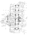
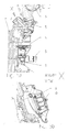
- FIG. 1 and 2 show an exhaust gas turbocharger (ATL) console 5, which is fastened by means of a mounting flange 26 to the internal combustion engine 7.
- the ATL console 5 has two Abgas 1500flansche 1, which allow the exhaust gas flow from the exhaust pipe to the exhaust gas turbocharger 9.
- FIG. 1 the interfaces of the exhaust gas recirculation can be seen on the narrow exhaust pipes 2, 3 for operation with EGR cooler. In an application without EGR cooler, these interfaces could be with blind plugs be closed.
- the exhaust gas turbocharger is arranged by means of the ATL console 5 on the charge air line.
- the exhaust pipes 2, 3 are decoupled from the console with respect to component expansions and manufacturing and assembly tolerances.
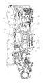
- FIG. 2 represents the solution with exhaust gas recirculation (EGR) cooler 21, which is installed at the same height with the narrow exhaust pipes for integrated pre-cooling and optimization of the EGR cooler length.
- the ATL console 5 is connected to the exhaust gas turbocharger 9 by means of an ATL flange 6. Within the ATL console 5, the two exhaust gas lines are brought together so that the exhaust gas flow ATL console 5 leaves via ATL flange 6 in the direction of the exhaust gas turbocharger 9 in order to drive the exhaust gas turbocharger 9 and then leave it as exhaust gas.
- EGR exhaust gas recirculation
- FIG. 3a is a precompletion of the front partial exhaust pipe 2 from FIG. 1 and in FIG. 3b The plug-in tubes 4, 8 of the front 2 and rear part of the exhaust pipe 3 from FIG. 1 shown.
- Figure 3c shows a Vorkompletttechnik of the rear partial exhaust pipe 3 from FIG. 1 with the plug-in tube 4, which is arranged between ATL console 5 and partial exhaust pipe 3 and the plug-in pipe 8, which is arranged between the partial exhaust pipe 3 and EGR cooler 21.
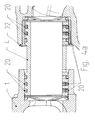
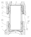
- FIGS. 4a . 4b . 4c show a Steck Sharing Museum 4 between ATL console 5 and partial exhaust pipe 2, 3.
- the plug pipe 4 or 8 is pressed into the corresponding receiving bore on the ATL console 5 or the EGR cooler 21 with the fit H7 / h6.
- the receiving bore may include a steel sleeve 22 in an alternative embodiment.
- FIG. 4b shown circumferential ring contact 20 seals against the environment as a circumferential connection.
- the Steck Glantz 4 and 8 is made of high temperature resistant steel to compensate for temperature differences of about 650 - 700 ° C.
- the thermal expansion coefficient of the plug-in tube 4 or 8 is adjusted so that the fit seals in each temperature range.
- This in FIG. 4b shown Steck Sharingrohr 4 and 8 is coated on the outside with a corrosion protection containing chromium carbide and MCrAlY particles.
- the exhaust pipes 2, 3 are decoupled from the console with respect to component expansions and manufacturing and assembly tolerances.
- the circumferential ring contact 20 seals as a peripheral connection against the environment and can be represented by one of the three connection options (Fey, Drahtgestrick, Parker Airduct).
- Fig. 4a a variant with lamellar rings is shown, which ensure the seal between the plug tube 4 and steel sleeve 22.
- Fig. 4b a variant is shown with a trained as a coupling piece piece pipe 4 with ring contacts 20, which contribute to the seal between male and 22 steel bushing.
- Fig. 4c a variant is shown in which the seal between the steel sleeve 22 and 4 Steck Suite Museum are represented by wire mesh, steel rings and corrugated springs.
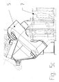
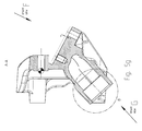
- FIGS. 5a, 5b . 5c . 5d . 5e, 5f and 5g show different representations of the arranged on the internal combustion engine 7 ATL console 5, wherein the exhaust gas turbocharger 9 on the internal combustion engine 7 opposite side (above) of the ATL console 5 is arranged.
- the ATL console 5 is connected by means of the ATL flange 6 with the only visible in Figure 5a exhaust gas turbocharger 9.
- the internal combustion engine 7 is in FIG. 5b only slightly to see, the exhaust gas turbocharger not at all.
- the ATL console 5 has an exhaust passage 10 in the console, which is framed by the ATL flange 6, as shown in FIG FIG. 5b you can see.
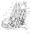
- FIG. 6 shows an ATL console 5, which is fastened by means of a mounting flange 26 to the internal combustion engine 7.
- the ATL console 5 has two Abgasschreib 1500flansche 1, which allow the return of the exhaust gas to the exhaust gas turbocharger 9.
- FIG. 1 the exhaust gas recirculation flanges 1 can be seen on the narrow exhaust pipes 2, 3 for operation with EGR cooler 21.
- the exhaust gas turbocharger 9 is arranged by means of the ATL console 5 on the charge air line.
- the exhaust pipes 2, 3 are decoupled from the console by means of Fey rings, in particular with respect to component expansions. This will be more detailed in the FIGS. 3a . 3b . 3c and 4a . 4b . 4c shown.
- the ATL console 5 of the exhaust gas turbocharger on the one hand holder of the exhaust gas turbocharger 9, on the other hand leads the ATL console 5, the exhaust gas of the exhaust pipes 2, 3 towards the exhaust gas turbocharger.
Landscapes
- Engineering & Computer Science (AREA)
- Chemical & Material Sciences (AREA)
- Combustion & Propulsion (AREA)
- Mechanical Engineering (AREA)
- General Engineering & Computer Science (AREA)
- Supercharger (AREA)
- Exhaust-Gas Circulating Devices (AREA)
Abstract
2. Die Erfindung betrifft eine Brennkraftmaschine mit einem Kurbelgehäuse, in dem eine Kurbelwelle drehbar gelagert ist, an der zumindest ein einen Kolben tragendes Pleuel angelenkt ist, wobei der Kolben in einem von einem Zylinderkopf abgedeckten Zylinder bewegbar ist, wobei in den Zylinderkopf Gaswechselventile eingebaut sind, die über Gaswechselkanäle mit einer Abgasleitung und einer Ladeluftleitung verbunden sind und wobei ein Abgasturbolader vorgesehen ist, der mittels einer Konsole an der Brennkraftmaschine befestigt ist und mit der Abgasleitung und der Ladeluftleitung verbunden ist.
Description
- Die Erfindung betrifft eine Vorrichtung zur Abgasführung.
- Derartige Vorrichtungen sind bekannt aus der
WO 2011/151379 A1 . Offenbart wird eine Brennkraftmaschine mit einem Einlasssystem, einem Auslasssystem und einem Abgasrückführsystem, sowie mit zumindest einem Abgasturbolader (ATL), mit einer Abgasturbine und einem Verdichter, wobei einer ersten Gruppe von Zylindern ein erster Einlassstrang und ein erster Auslassstrang und einer zweiten Gruppe von Zylindern ein zweiter Einlassstrang und ein zweiter Auslassstrang zugeordnet ist, wobei eine erste Abgasrückführleitung von einem ersten Abgasstrang stromaufwärts der Abgasturbine abzweigt und in einen ersten Einlassstrang stromabwärts des Verdichters einmündet, und wobei eine zweite Abgasrückführleitung von einem zweiten Abgasstrang stromaufwärts der Abgasturbine abzweigt und in einen zweiten Einlassstrang stromabwärts des Verdichters einmündet, wobei der erste Einlassstrang ein erstes Resonanzrohr und der zweite Einlassstrang ein zweites Resonanzrohr aufweist. Die Mündungsbereiche der ersten und zweiten Abgasrückführleitungen sind am Beginn der ersten bzw. der zweiten Resonanzrohre angeordnet. Daran ist nachteilig, dass die Verrohrung aufwendig und teuer ist, die Leitungswege unterschiedlich lang sind. - Weiter ist eine V-förmige Brennkraftmaschine aus der
DE 101 22 406 B4 bekannt, bei der der Ausgang des Kanals für den Schmiermittelrücklauf der Konsole und der Eingang des Kanals für den Schmiermittelrücklauf der Konsole achsversetzt zueinander angeordnet sind. - Ein Trägergehäuse für eine Brennkraftmaschine mit einem Motorblock mit einer V-Anordnung von Zylindern und mit einer Aufladegruppe wird in der
WO 2012/038037 A1 offenbart. Ein weiterer Nachteil bei Traktoren ist, dass sie einen sehr schmalen Bauraum haben, der unter anderem durch den erforderlichen engen Radeinschlag verursacht wird, seitlicher Bauraum am Motor ist deshalb schwer zugänglich. - Es ist die Aufgabe der vorliegenden Erfindung, die oben genannten Nachteile zu vermeiden und eine Brennkraftmaschine und ein Verfahren zum Betreiben derselben zu schaffen, die die künftigen Abgasregelungen bei vertretbaren Kosten einhält.
- Gelöst wird die Aufgabe durch eine Brennkraftmaschine mit einem Kurbelgehäuse, in dem eine Kurbelwelle drehbar gelagert ist, an der zumindest ein einen Kolben tragendes Pleuel angelenkt ist, wobei der Kolben in einem von einem Zylinderkopf abgedeckten Zylinder bewegbar ist, wobei in den Zylinderkopf Gaswechselventile eingebaut sind, die über Gaswechselkanäle mit einer wenigstens zweiteiligen Abgasleitung und einer Ladeluftleitung verbunden sind und wobei ein Abgasturbolader vorgesehen ist, der mittels einer Konsole an der Brennkraftmaschine befestigt ist und mit der Abgasleitung und der Ladeluftleitung verbunden ist, wobei die Konsole zwischen dem Abgasturbolader und der Brennkraftmaschine angeordnet ist und die Konsole das Abgas führt. Eine vorteilhafte Weiterbildung sieht vor, dass die Konsole am Zylinderkopf befestigt ist, was vorteilhaft ist, wenn es schmale Bauräume gibt.
- Weitere vorteilhafte Ausgestaltungen sind in den Unteransprüchen enthalten.
- Bevorzugte Ausführungsbeispiele der Erfindung sind in den Zeichnungen dargestellt und werden in der nachfolgenden Beschreibung näher erläutert, wobei sich gleiche Bezugszeichen auf gleiche oder ähnliche Bauteile beziehen. Es zeigen:
- Figur 1
- eine Seitenansicht der Brennkraftmaschine mit ATL-Konsole,
- Figur 2a
- eine Seitenansicht der Brennkraftmaschine mit ATL-Konsole und AGR-Kühler,
- Figur 2b
- eine Vorderansicht der Brennkraftmaschine mit ATL-Konsole und AGR-Kühler,
- Figur 3a
- eine Vorkomplettierung des vorderen Rohres aus
Figur 1 , - Figur 3b
- die Steckstückrohre des vorderen bzw. hinteren Rohres aus
Figur 1 , - Figur 3c
- eine Vorkomplettierung des hinteren Rohres aus
Figur 1 , - Figur 4a
- ein Steckstückrohr zwischen Konsole und Teilabgasleitungsrohr mit Lamellenringen,
- Figur 4b
- ein Steckstückrohr zwischen Konsole und Teilabgasleitung,
- Figur 4c
- ein Steckstückrohr zwischen Konsole und Teilabgasleitungsrohr mit Drehgestrick, Stahlringen und Wellfedern,
- Figuren 5a - 5g
- verschieden Darstellungen der ATL-Konsole,
- Figur 6
- eine Draufsicht auf die Brennkraftmaschine.
-
Figur 1 und2 zeigen eine Abgasturbolader (ATL)-Konsole 5, die mittels eines Befestigungsflansches 26 an der Brennkraftmaschine 7 befestigt ist. Die ATL-Konsole 5 weist zwei Abgasführflansche 1 auf, die den Abgasführstrom von der Abgasleitung zum Abgasturbolader 9 ermöglichen. InFigur 1 sind die Schnittstellen der Abgasrückführung an den schmalen Abgasleitungen 2, 3 für den Betrieb mit AGR-Kühler zu sehen. Bei einem Anwendungsfall ohne AGR-Kühler könnten diese Schnittstellen mit Blindstopfen verschlossen werden. Der Abgasturbolader ist mittels der ATL-Konsole 5 auf der Ladeluftleitung angeordnet. Die Abgasleitungen 2, 3 sind von der Konsole in Bezug auf Bauteildehnungen und Fertigungs- und Montagetoleranzen entkoppelt. Als Entkopplungssysteme können Lamellen-Ringe von "Fey", Steckstückverbindungen mit Drahtgestrickelementen oder auch ein Kupplungsstück wie bei der Verbindung des "Parker Airducts" vorgesehen werden. Detaillierter wird dies in denFiguren 3a ,3b ,3c und4a ,4b ,4c dargestellt. Die ATL-Konsole 5 des Abgasturboladers ist einerseits Halterung des Abgasturboladers 9, andererseits führt die ATL-Konsole 5 das Abgas der Abgasleitungen 2, 3 hin zum Abgasturbolader 9. -
Figur 2 stellt die Lösung mit Abgasrückführ (AGR)-Kühler 21 dar, der auf gleicher Höhe mit den schmalen Abgasleitungen zur integrierten Vorkühlung und Optimierung der AGR-Kühlerlänge verbaut ist. Die ATL-Konsole 5 ist mittels eines ATL-Flansches 6 mit dem Abgasturbolader 9 verbunden. Innerhalb der ATL-Konsole 5 werden die beiden Abgasstränge zusammengeführt, so dass der Abgasstrom ATL-Konsole 5 via ATL-Flansch 6 in Richtung Abgasturbolader 9 verlässt, um den Abgasturbolader 9 anzutreiben und diesen dann als Abgas zu verlassen. - In
Figur 3a wird eine Vorkomplettierung der vorderen Teil-Abgasleitung 2 ausFigur 1 und inFigur 3b ie Steckstückrohre 4, 8 der vorderen 2 bzw. hinteren Teil-Abgasleitung 3 ausFigur 1 gezeigt. -
Figur 3c zeigt eine Vorkomplettierung der hinteren Teil-Abgasleitung 3 ausFigur 1 mit dem Steckstückrohr 4, das zwischen ATL-Konsole 5 und Teilabgasleitungsrohr 3 angeordnet ist und dem Steckstückrohr 8, das zwischen Teilabgasleitungsrohr 3 und AGR-Kühler 21 angeordnet ist. -
Figuren 4a ,4b ,4c zeigen ein Steckstückrohr 4 zwischen ATL-Konsole 5 und Teilabgasleitungsrohr 2, 3. Das Steckstückrohr 4 bzw. 8 wird in die korrespondierende Aufnahmebohrung an der ATL-Konsole 5 oder dem AGR-Kühler 21 mit der Passung H7/h6 eingepresst. Die Aufnahmebohrung kann in einer alternativen Ausgestaltung eine Stahlbuchse 22 enthalten. - Der in
Figur 4b dargestellte umlaufende Ringkontakt 20 dichtet gegen die Umgebung als umlaufende Verbindung ab. InFigur 4a und4b erfolgt die Abdichtung mittels Flächenkontakt. Das Steckstückrohr 4 bzw. 8 besteht aus hochtemperaturbeständigem Stahl, um Temperaturdifferenzen von etwa 650 - 700°C auszugleichen. Der Wärmedehnungskoeffizient des Steckstückrohres 4 bzw. 8 ist so abgestimmt, dass die Passung in jedem Temperaturbereich abdichtet. Das inFigur 4b dargestellte Steckstückrohr 4 bzw. 8 ist außen beschichtet mit einem Korrosionsschutz, der Chromkarbid und MCrAlY-Partikel enthält. Die Abgasleitungen 2, 3 sind von der Konsole in Bezug auf Bauteildehnungen und Fertigungs- und Montagetoleranzen entkoppelt. Als Entkopplungssysteme können Lamellen-Ringe von "Fey", Steckstückverbindungen mit Drahtgestrickelementen oder auch ein Kupplungsstück wie bei der Verbindung des "Parker Airducts" vorgesehen werden. Der umlaufende Ringkontakt 20 dichtet als umlaufende Verbindung gegen die Umgebung ab und kann durch eine der drei Verbindungsmöglichkeiten (Fey, Drahtgestrick, Parker Airduct) dargestellt werden. - In
Fig. 4a wird eine Variante mit Lamellen-Ringen dargestellt, die die Dichtung zwischen Steckstückrohr 4 und Stahlbuchse 22 sicherstellen. - In
Fig. 4b wird eine Variante dargestellt mit einem als Kupplungsstück ausgebildeten Steckstückrohr 4 mit Ringkontakten 20, die zur Dichtung zwischen Steckstück und Stahlbuchse 22 beitragen. - In
Fig. 4c wird eine Variante dargestellt, bei der die Abdichtung zwischen Stahlbuchse 22 und Steckstückrohr 4 mittels Drahtgestrick, Stahlringen und Wellfedern dargestellt werden. - Die
Figuren 5a, 5b ,5c ,5d ,5e, 5f und5g zeigen verschieden Darstellungen der an der Brennkraftmaschine 7 angeordneten ATL-Konsole 5, wobei der Abgasturbolader 9 auf der der Brennkraftmaschine 7 gegenüberliegenden Seite (oberhalb) der ATL-Konsole 5 angeordnet ist. - Die ATL-Konsole 5 ist mittels des ATL-Flansches 6 mit dem lediglich in Figur 5a sichtbaren Abgasturbolader 9 verbunden. Die Brennkraftmaschine 7 ist in
Figur 5b nur ansatzweise zu sehen, der Abgasturbolader gar nicht. - Die ATL-Konsole 5 weist einen Abgaskanal 10 in der Konsole auf, der vom ATL-Flansch 6 umrahmt wird, wie dies in
Figur 5b zu sehen ist. -
Figur 6 zeigt eine ATL-Konsole 5, die mittels eines Befestigungsflansches 26 an der Brennkraftmaschine 7 befestigt ist. Die ATL-Konsole 5 weist zwei Abgasrückführflansche 1 auf, die die Rückführung des Abgases zum Abgasturbolader 9 ermöglichen. InFigur 1 sind die Abgasrückführflansche 1 an den schmalen Abgasleitungen 2, 3 für den Betrieb mit AGR-Kühler 21 zu sehen. Der Abgasturbolader 9 ist mittels der ATL-Konsole 5 auf der Ladeluftleitung angeordnet. Die Abgasleitungen 2, 3 sind von der Konsole mittels Fey-Ringe insbesondere in Bezug auf Bauteildehnungen entkoppelt. Detaillierter wird dies in denFiguren 3a ,3b ,3c und4a ,4b ,4c dargestellt. Die ATL-Konsole 5 des Abgasturboladers ist einerseits Halterung des Abgasturboladers 9, andererseits führt die ATL-Konsole 5 das Abgas der Abgasleitungen 2, 3 hin zum Abgasturbolader 9. -
- 1
- Abgasrückführflansch
- 2
- Teil-Abgasleitung
- 3
- Teil-Abgasleitung
- 4
- Steckstückrohr zwischen Konsole und Teilabgasleitungsrohr
- 5
- Abgasturbolader-Konsole
- 6
- Abgasturbolader-Flansch
- 7
- Brennkraftmaschine
- 8
- Steckstückrohr zwischen Teilabgasleitungsrohr und AGR-Kühler
- 9
- Abgasturbolader
- 10
- Abgaskanal in der Konsole
- 20
- Ringkontakt
- 21
- AGR-Kühler
- 22
- Stahlbuchse
- 26
- Befestigungsflansch
Claims (10)
- Brennkraftmaschine mit einem Kurbelgehäuse, in dem eine Kurbelwelle drehbar gelagert ist, an der zumindest ein einen Kolben tragendes Pleuel angelenkt ist, wobei der Kolben in einem von einem Zylinderkopf abgedeckten Zylinder bewegbar ist, wobei in den Zylinderkopf Gaswechselventile eingebaut sind, die über Gaswechselkanäle mit einer Abgasleitung und einer Ladeluftleitung verbunden sind und wobei ein Abgasturbolader vorgesehen ist, der mittels einer Konsole an der Brennkraftmaschine befestigt ist und mit der Abgasleitung und der Ladeluftleitung verbunden ist, dadurch gekennzeichnet, dass die ATL-Konsole (5) zwischen dem Abgasturbolader 9 und der Brennkraftmaschine angeordnet ist und dass die ATL-Konsole (5) das Abgas führt.
- Brennkraftmaschine nach Anspruch 1,
dadurch gekennzeichnet, dass die ATL-Konsole (5) am Zylinderkopf befestigt ist. - Brennkraftmaschine nach Anspruch 1 oder 2,
dadurch gekennzeichnet, dass die Abgasleitung (2) zweigeteilt ist. - Brennkraftmaschine nach einem oder mehreren der vorgenannten Ansprüche,
dadurch gekennzeichnet, dass die Verbindung zwischen Abgasleitung (2, 3) und ATL-Konsole (5) mittels wenigstens eines Steckstückrohrs (4) ausgeführt ist. - Brennkraftmaschine nach einem oder mehreren der vorgenannten Ansprüche,
dadurch gekennzeichnet, dass die Verbindung zwischen Abgasleitung (2, 3) und AGR mittels wenigstens eines Steckstückrohrs (8) ausgeführt ist. - Brennkraftmaschine nach einem oder mehreren der vorgenannten Ansprüche,
dadurch gekennzeichnet, dass sie einen Ladeluftkühler aufweist. - Brennkraftmaschine nach einem oder mehreren der vorgenannten Ansprüche,
dadurch gekennzeichnet, dass zur Abführung des Abgases im Abgastrakt wenigstens eine Leitung zur Abgasrückführung vorgesehen ist, die von der Abgasleitung abzweigt und einen AGR-Kühler (21) aufweist und in die Ansaugleitung des Ansaugtrakts mündet. - Brennkraftmaschine nach einem oder mehreren der vorgenannten Ansprüche,
dadurch gekennzeichnet, dass der wenigstens eine AGR-Kühler (21) im Wesentlichen an einer Brennkraftmaschinenlängsseite angeordnet ist. - Brennkraftmaschine nach einem oder mehreren der vorgenannten Ansprüche,
dadurch gekennzeichnet, dass zur Abführung des Abgases im Abgastrakt wenigstens eine Leitung zur Abgasrückführung vorgesehen ist, die von der Abgasleitung abzweigt und in die Ansaugleitung mündet, wobei in der Leitung zur Abgasrückführung wenigstens ein weiterer Verdichter zur Förderung der rückzuführenden Abgasmenge vorgesehen ist, wobei eine Bypassleitung unter Ausbildung einer Abzweigung stromaufwärts des Verdichters von der Rückführleitung abzweigt und unter Ausbildung einer Einmündung stromabwärts des Verdichters wieder in die Rückführleitung mündet. - Verfahren zum Betreiben einer Brennkraftmaschine,
dadurch gekennzeichnet, dass eine Brennkraftmaschine nach einem oder mehreren der vorgenannten Ansprüche zum Einsatz kommt.
Applications Claiming Priority (1)
| Application Number | Priority Date | Filing Date | Title |
|---|---|---|---|
| DE102014017974.5A DE102014017974A1 (de) | 2014-12-04 | 2014-12-04 | Vorrichtung zur Abgasführung |
Publications (3)
| Publication Number | Publication Date |
|---|---|
| EP3029296A2 true EP3029296A2 (de) | 2016-06-08 |
| EP3029296A3 EP3029296A3 (de) | 2016-06-22 |
| EP3029296B1 EP3029296B1 (de) | 2018-03-21 |
Family
ID=54476639
Family Applications (1)
| Application Number | Title | Priority Date | Filing Date |
|---|---|---|---|
| EP15003149.0A Active EP3029296B1 (de) | 2014-12-04 | 2015-11-03 | Vorrichtung zur abgasführung |
Country Status (2)
| Country | Link |
|---|---|
| EP (1) | EP3029296B1 (de) |
| DE (1) | DE102014017974A1 (de) |
Citations (3)
| Publication number | Priority date | Publication date | Assignee | Title |
|---|---|---|---|---|
| DE10122406B4 (de) | 2001-05-09 | 2004-05-27 | Mtu Friedrichshafen Gmbh | Brennkraftmaschine mit Aufladegruppe |
| WO2011151379A1 (de) | 2010-06-02 | 2011-12-08 | Avl List Gmbh | Brennkraftmaschine |
| WO2012038037A1 (de) | 2010-09-20 | 2012-03-29 | Mtu Friedrichshafen Gmbh | Trägergehäuse und brennkraftmaschine |
Family Cites Families (5)
| Publication number | Priority date | Publication date | Assignee | Title |
|---|---|---|---|---|
| US6164071A (en) * | 1997-09-08 | 2000-12-26 | Cummins Engine Company, Inc. | EGR delivery and control system using dedicated full authority compressor |
| US8235685B2 (en) * | 2008-08-12 | 2012-08-07 | GM Global Technology Operations LLC | Turbocharger mount with integrated exhaust and exhaust gas recirculation connections |
| CN102358171A (zh) * | 2011-08-05 | 2012-02-22 | 无锡开普动力有限公司 | 一种增压器排气管支撑装置 |
| GB2494144A (en) * | 2011-08-30 | 2013-03-06 | Gm Global Tech Operations Inc | Turbocharger to exhaust manifold connection |
| JP2013189921A (ja) * | 2012-03-14 | 2013-09-26 | Ihi Corp | 過給機 |
-
2014
- 2014-12-04 DE DE102014017974.5A patent/DE102014017974A1/de not_active Withdrawn
-
2015
- 2015-11-03 EP EP15003149.0A patent/EP3029296B1/de active Active
Patent Citations (3)
| Publication number | Priority date | Publication date | Assignee | Title |
|---|---|---|---|---|
| DE10122406B4 (de) | 2001-05-09 | 2004-05-27 | Mtu Friedrichshafen Gmbh | Brennkraftmaschine mit Aufladegruppe |
| WO2011151379A1 (de) | 2010-06-02 | 2011-12-08 | Avl List Gmbh | Brennkraftmaschine |
| WO2012038037A1 (de) | 2010-09-20 | 2012-03-29 | Mtu Friedrichshafen Gmbh | Trägergehäuse und brennkraftmaschine |
Also Published As
| Publication number | Publication date |
|---|---|
| EP3029296B1 (de) | 2018-03-21 |
| EP3029296A3 (de) | 2016-06-22 |
| DE102014017974A1 (de) | 2016-06-09 |
Similar Documents
| Publication | Publication Date | Title |
|---|---|---|
| DE102008047448B4 (de) | Abgasturbolader | |
| DE102014100739A1 (de) | Teilweise integrierter abgaskrümmer | |
| DE102016109770A1 (de) | Wassergekühlte Abgassammelleitung | |
| DE102006058102A1 (de) | Brennkraftmaschine mit Abgasturbolader | |
| DE112015006356B4 (de) | Abgaskrümmeranordnung, Verfahren zum Installieren eines Balgs in eine Abgaskrümmeranordnung sowie Verbrennungsmotorsystem | |
| DE102016208160A1 (de) | Turbine für einen Abgasturbolader mit zweiflutigem Turbinengehäuse und einer Ventil-Anordnung mit verbesserter Abströmung | |
| EP3029296B1 (de) | Vorrichtung zur abgasführung | |
| EP3523514B1 (de) | Vorrichtung zur entlüftung eines kurbelgehäuses einer verbrennungskraftmaschine | |
| DE102011018275A1 (de) | Rohrleitung für ein Kraftfahrzeug | |
| DE10339111B4 (de) | EGR-Leitung mit Doppeldichtungseinheit | |
| DE2945570A1 (de) | Turbolader-bypass-steuerung | |
| DE102018218886A1 (de) | Rücklaufleitung-Anordnung | |
| DE102013006302A1 (de) | Aufgeladene Brennkraftmaschine in Baukastenbauform und Baukastensysteme für solche Brennkraftmaschinen sowie Aufladungseinrichtungen | |
| EP2764219B1 (de) | Brennkraftmaschine sowie verfahren zum betreiben einer brennkraftmaschine | |
| DE10121498A1 (de) | Abgassystem für eine Brennkraftmaschine | |
| EP2848785A1 (de) | Abgasleitung einer Brennkraftmaschine | |
| DE102014216461A1 (de) | Brennkraftmaschine | |
| DE102016005852A1 (de) | Abgasrohr zum Führen von Abgas einer Verbrennungskraftmaschine, insbesondere für ein Kraftfahrzeug | |
| DE202014102265U1 (de) | Schlauch und System zur Schlauchklemmenregistrierung | |
| DE202015003497U1 (de) | Entlüftungssystem für Kurbelgehäuse und Tank | |
| DE112020006468B4 (de) | Abgassystem einer Verbrennungskraftmaschine | |
| DE102007054953A1 (de) | Luftgekühlter Abgasrückführkühler | |
| DE10130013A1 (de) | Abgasrückführanordnung | |
| DE102012025048A1 (de) | Verbrennungskraftmaschine für einen Kraftwagen | |
| DE102011010995A1 (de) | Steckrohrverbindung zwischen getrennten Lagergehäusen von zwei Abgasturboladern |
Legal Events
| Date | Code | Title | Description |
|---|---|---|---|
| PUAL | Search report despatched |
Free format text: ORIGINAL CODE: 0009013 |
|
| PUAI | Public reference made under article 153(3) epc to a published international application that has entered the european phase |
Free format text: ORIGINAL CODE: 0009012 |
|
| AK | Designated contracting states |
Kind code of ref document: A2 Designated state(s): AL AT BE BG CH CY CZ DE DK EE ES FI FR GB GR HR HU IE IS IT LI LT LU LV MC MK MT NL NO PL PT RO RS SE SI SK SM TR |
|
| AX | Request for extension of the european patent |
Extension state: BA ME |
|
| AK | Designated contracting states |
Kind code of ref document: A3 Designated state(s): AL AT BE BG CH CY CZ DE DK EE ES FI FR GB GR HR HU IE IS IT LI LT LU LV MC MK MT NL NO PL PT RO RS SE SI SK SM TR |
|
| AX | Request for extension of the european patent |
Extension state: BA ME |
|
| RIC1 | Information provided on ipc code assigned before grant |
Ipc: F02B 37/00 20060101ALI20160513BHEP Ipc: F02B 67/10 20060101AFI20160513BHEP |
|
| 17P | Request for examination filed |
Effective date: 20161216 |
|
| RBV | Designated contracting states (corrected) |
Designated state(s): AL AT BE BG CH CY CZ DE DK EE ES FI FR GB GR HR HU IE IS IT LI LT LU LV MC MK MT NL NO PL PT RO RS SE SI SK SM TR |
|
| 17Q | First examination report despatched |
Effective date: 20170215 |
|
| GRAP | Despatch of communication of intention to grant a patent |
Free format text: ORIGINAL CODE: EPIDOSNIGR1 |
|
| INTG | Intention to grant announced |
Effective date: 20171011 |
|
| GRAS | Grant fee paid |
Free format text: ORIGINAL CODE: EPIDOSNIGR3 |
|
| GRAA | (expected) grant |
Free format text: ORIGINAL CODE: 0009210 |
|
| AK | Designated contracting states |
Kind code of ref document: B1 Designated state(s): AL AT BE BG CH CY CZ DE DK EE ES FI FR GB GR HR HU IE IS IT LI LT LU LV MC MK MT NL NO PL PT RO RS SE SI SK SM TR |
|
| REG | Reference to a national code |
Ref country code: GB Ref legal event code: FG4D Free format text: NOT ENGLISH |
|
| REG | Reference to a national code |
Ref country code: CH Ref legal event code: EP |
|
| REG | Reference to a national code |
Ref country code: AT Ref legal event code: REF Ref document number: 981368 Country of ref document: AT Kind code of ref document: T Effective date: 20180415 |
|
| REG | Reference to a national code |
Ref country code: IE Ref legal event code: FG4D Free format text: LANGUAGE OF EP DOCUMENT: GERMAN |
|
| REG | Reference to a national code |
Ref country code: DE Ref legal event code: R096 Ref document number: 502015003491 Country of ref document: DE |
|
| REG | Reference to a national code |
Ref country code: NL Ref legal event code: MP Effective date: 20180321 |
|
| PG25 | Lapsed in a contracting state [announced via postgrant information from national office to epo] |
Ref country code: NO Free format text: LAPSE BECAUSE OF FAILURE TO SUBMIT A TRANSLATION OF THE DESCRIPTION OR TO PAY THE FEE WITHIN THE PRESCRIBED TIME-LIMIT Effective date: 20180621 Ref country code: FI Free format text: LAPSE BECAUSE OF FAILURE TO SUBMIT A TRANSLATION OF THE DESCRIPTION OR TO PAY THE FEE WITHIN THE PRESCRIBED TIME-LIMIT Effective date: 20180321 Ref country code: LT Free format text: LAPSE BECAUSE OF FAILURE TO SUBMIT A TRANSLATION OF THE DESCRIPTION OR TO PAY THE FEE WITHIN THE PRESCRIBED TIME-LIMIT Effective date: 20180321 Ref country code: CY Free format text: LAPSE BECAUSE OF FAILURE TO SUBMIT A TRANSLATION OF THE DESCRIPTION OR TO PAY THE FEE WITHIN THE PRESCRIBED TIME-LIMIT Effective date: 20180321 Ref country code: HR Free format text: LAPSE BECAUSE OF FAILURE TO SUBMIT A TRANSLATION OF THE DESCRIPTION OR TO PAY THE FEE WITHIN THE PRESCRIBED TIME-LIMIT Effective date: 20180321 |
|
| REG | Reference to a national code |
Ref country code: LT Ref legal event code: MG4D |
|
| PG25 | Lapsed in a contracting state [announced via postgrant information from national office to epo] |
Ref country code: RS Free format text: LAPSE BECAUSE OF FAILURE TO SUBMIT A TRANSLATION OF THE DESCRIPTION OR TO PAY THE FEE WITHIN THE PRESCRIBED TIME-LIMIT Effective date: 20180321 Ref country code: BG Free format text: LAPSE BECAUSE OF FAILURE TO SUBMIT A TRANSLATION OF THE DESCRIPTION OR TO PAY THE FEE WITHIN THE PRESCRIBED TIME-LIMIT Effective date: 20180621 Ref country code: SE Free format text: LAPSE BECAUSE OF FAILURE TO SUBMIT A TRANSLATION OF THE DESCRIPTION OR TO PAY THE FEE WITHIN THE PRESCRIBED TIME-LIMIT Effective date: 20180321 Ref country code: LV Free format text: LAPSE BECAUSE OF FAILURE TO SUBMIT A TRANSLATION OF THE DESCRIPTION OR TO PAY THE FEE WITHIN THE PRESCRIBED TIME-LIMIT Effective date: 20180321 Ref country code: GR Free format text: LAPSE BECAUSE OF FAILURE TO SUBMIT A TRANSLATION OF THE DESCRIPTION OR TO PAY THE FEE WITHIN THE PRESCRIBED TIME-LIMIT Effective date: 20180622 |
|
| PG25 | Lapsed in a contracting state [announced via postgrant information from national office to epo] |
Ref country code: MT Free format text: LAPSE BECAUSE OF FAILURE TO SUBMIT A TRANSLATION OF THE DESCRIPTION OR TO PAY THE FEE WITHIN THE PRESCRIBED TIME-LIMIT Effective date: 20180321 |
|
| PG25 | Lapsed in a contracting state [announced via postgrant information from national office to epo] |
Ref country code: PL Free format text: LAPSE BECAUSE OF FAILURE TO SUBMIT A TRANSLATION OF THE DESCRIPTION OR TO PAY THE FEE WITHIN THE PRESCRIBED TIME-LIMIT Effective date: 20180321 Ref country code: EE Free format text: LAPSE BECAUSE OF FAILURE TO SUBMIT A TRANSLATION OF THE DESCRIPTION OR TO PAY THE FEE WITHIN THE PRESCRIBED TIME-LIMIT Effective date: 20180321 Ref country code: ES Free format text: LAPSE BECAUSE OF FAILURE TO SUBMIT A TRANSLATION OF THE DESCRIPTION OR TO PAY THE FEE WITHIN THE PRESCRIBED TIME-LIMIT Effective date: 20180321 Ref country code: NL Free format text: LAPSE BECAUSE OF FAILURE TO SUBMIT A TRANSLATION OF THE DESCRIPTION OR TO PAY THE FEE WITHIN THE PRESCRIBED TIME-LIMIT Effective date: 20180321 Ref country code: RO Free format text: LAPSE BECAUSE OF FAILURE TO SUBMIT A TRANSLATION OF THE DESCRIPTION OR TO PAY THE FEE WITHIN THE PRESCRIBED TIME-LIMIT Effective date: 20180321 Ref country code: IT Free format text: LAPSE BECAUSE OF FAILURE TO SUBMIT A TRANSLATION OF THE DESCRIPTION OR TO PAY THE FEE WITHIN THE PRESCRIBED TIME-LIMIT Effective date: 20180321 Ref country code: AL Free format text: LAPSE BECAUSE OF FAILURE TO SUBMIT A TRANSLATION OF THE DESCRIPTION OR TO PAY THE FEE WITHIN THE PRESCRIBED TIME-LIMIT Effective date: 20180321 |
|
| PG25 | Lapsed in a contracting state [announced via postgrant information from national office to epo] |
Ref country code: SK Free format text: LAPSE BECAUSE OF FAILURE TO SUBMIT A TRANSLATION OF THE DESCRIPTION OR TO PAY THE FEE WITHIN THE PRESCRIBED TIME-LIMIT Effective date: 20180321 Ref country code: SM Free format text: LAPSE BECAUSE OF FAILURE TO SUBMIT A TRANSLATION OF THE DESCRIPTION OR TO PAY THE FEE WITHIN THE PRESCRIBED TIME-LIMIT Effective date: 20180321 Ref country code: CZ Free format text: LAPSE BECAUSE OF FAILURE TO SUBMIT A TRANSLATION OF THE DESCRIPTION OR TO PAY THE FEE WITHIN THE PRESCRIBED TIME-LIMIT Effective date: 20180321 |
|
| PG25 | Lapsed in a contracting state [announced via postgrant information from national office to epo] |
Ref country code: PT Free format text: LAPSE BECAUSE OF FAILURE TO SUBMIT A TRANSLATION OF THE DESCRIPTION OR TO PAY THE FEE WITHIN THE PRESCRIBED TIME-LIMIT Effective date: 20180723 |
|
| REG | Reference to a national code |
Ref country code: DE Ref legal event code: R097 Ref document number: 502015003491 Country of ref document: DE |
|
| PLBE | No opposition filed within time limit |
Free format text: ORIGINAL CODE: 0009261 |
|
| STAA | Information on the status of an ep patent application or granted ep patent |
Free format text: STATUS: NO OPPOSITION FILED WITHIN TIME LIMIT |
|
| PG25 | Lapsed in a contracting state [announced via postgrant information from national office to epo] |
Ref country code: DK Free format text: LAPSE BECAUSE OF FAILURE TO SUBMIT A TRANSLATION OF THE DESCRIPTION OR TO PAY THE FEE WITHIN THE PRESCRIBED TIME-LIMIT Effective date: 20180321 |
|
| 26N | No opposition filed |
Effective date: 20190102 |
|
| PG25 | Lapsed in a contracting state [announced via postgrant information from national office to epo] |
Ref country code: SI Free format text: LAPSE BECAUSE OF FAILURE TO SUBMIT A TRANSLATION OF THE DESCRIPTION OR TO PAY THE FEE WITHIN THE PRESCRIBED TIME-LIMIT Effective date: 20180321 |
|
| REG | Reference to a national code |
Ref country code: CH Ref legal event code: PL |
|
| PG25 | Lapsed in a contracting state [announced via postgrant information from national office to epo] |
Ref country code: LU Free format text: LAPSE BECAUSE OF NON-PAYMENT OF DUE FEES Effective date: 20181103 Ref country code: MC Free format text: LAPSE BECAUSE OF FAILURE TO SUBMIT A TRANSLATION OF THE DESCRIPTION OR TO PAY THE FEE WITHIN THE PRESCRIBED TIME-LIMIT Effective date: 20180321 |
|
| REG | Reference to a national code |
Ref country code: BE Ref legal event code: MM Effective date: 20181130 |
|
| REG | Reference to a national code |
Ref country code: IE Ref legal event code: MM4A |
|
| PG25 | Lapsed in a contracting state [announced via postgrant information from national office to epo] |
Ref country code: LI Free format text: LAPSE BECAUSE OF NON-PAYMENT OF DUE FEES Effective date: 20181130 Ref country code: CH Free format text: LAPSE BECAUSE OF NON-PAYMENT OF DUE FEES Effective date: 20181130 |
|
| PG25 | Lapsed in a contracting state [announced via postgrant information from national office to epo] |
Ref country code: IE Free format text: LAPSE BECAUSE OF NON-PAYMENT OF DUE FEES Effective date: 20181103 Ref country code: FR Free format text: LAPSE BECAUSE OF NON-PAYMENT OF DUE FEES Effective date: 20181130 |
|
| PG25 | Lapsed in a contracting state [announced via postgrant information from national office to epo] |
Ref country code: BE Free format text: LAPSE BECAUSE OF NON-PAYMENT OF DUE FEES Effective date: 20181130 |
|
| PG25 | Lapsed in a contracting state [announced via postgrant information from national office to epo] |
Ref country code: TR Free format text: LAPSE BECAUSE OF FAILURE TO SUBMIT A TRANSLATION OF THE DESCRIPTION OR TO PAY THE FEE WITHIN THE PRESCRIBED TIME-LIMIT Effective date: 20180321 |
|
| PG25 | Lapsed in a contracting state [announced via postgrant information from national office to epo] |
Ref country code: HU Free format text: LAPSE BECAUSE OF FAILURE TO SUBMIT A TRANSLATION OF THE DESCRIPTION OR TO PAY THE FEE WITHIN THE PRESCRIBED TIME-LIMIT; INVALID AB INITIO Effective date: 20151103 Ref country code: MK Free format text: LAPSE BECAUSE OF NON-PAYMENT OF DUE FEES Effective date: 20180321 |
|
| PG25 | Lapsed in a contracting state [announced via postgrant information from national office to epo] |
Ref country code: IS Free format text: LAPSE BECAUSE OF FAILURE TO SUBMIT A TRANSLATION OF THE DESCRIPTION OR TO PAY THE FEE WITHIN THE PRESCRIBED TIME-LIMIT Effective date: 20180721 |
|
| GBPC | Gb: european patent ceased through non-payment of renewal fee |
Effective date: 20191103 |
|
| PG25 | Lapsed in a contracting state [announced via postgrant information from national office to epo] |
Ref country code: GB Free format text: LAPSE BECAUSE OF NON-PAYMENT OF DUE FEES Effective date: 20191103 |
|
| REG | Reference to a national code |
Ref country code: AT Ref legal event code: MM01 Ref document number: 981368 Country of ref document: AT Kind code of ref document: T Effective date: 20201103 |
|
| PG25 | Lapsed in a contracting state [announced via postgrant information from national office to epo] |
Ref country code: AT Free format text: LAPSE BECAUSE OF NON-PAYMENT OF DUE FEES Effective date: 20201103 |
|
| PGFP | Annual fee paid to national office [announced via postgrant information from national office to epo] |
Ref country code: DE Payment date: 20251204 Year of fee payment: 11 |