EP3029227B1 - Fitting with adjustable clamping area - Google Patents
Fitting with adjustable clamping area Download PDFInfo
- Publication number
- EP3029227B1 EP3029227B1 EP14196240.7A EP14196240A EP3029227B1 EP 3029227 B1 EP3029227 B1 EP 3029227B1 EP 14196240 A EP14196240 A EP 14196240A EP 3029227 B1 EP3029227 B1 EP 3029227B1
- Authority
- EP
- European Patent Office
- Prior art keywords
- fitting
- elements
- door
- designed
- holding
- Prior art date
- Legal status (The legal status is an assumption and is not a legal conclusion. Google has not performed a legal analysis and makes no representation as to the accuracy of the status listed.)
- Active
Links
- 239000011521 glass Substances 0.000 claims description 58
- 239000000463 material Substances 0.000 claims description 12
- 230000000452 restraining effect Effects 0.000 claims 4
- 125000006850 spacer group Chemical group 0.000 description 26
- 239000002184 metal Substances 0.000 description 7
- 238000001746 injection moulding Methods 0.000 description 3
- 238000003754 machining Methods 0.000 description 3
- 238000010276 construction Methods 0.000 description 2
- 230000001419 dependent effect Effects 0.000 description 2
- 238000003780 insertion Methods 0.000 description 2
- 230000037431 insertion Effects 0.000 description 2
- 238000009434 installation Methods 0.000 description 2
- 229910001092 metal group alloy Inorganic materials 0.000 description 2
- 238000003801 milling Methods 0.000 description 2
- 241000591215 Acraea andromacha Species 0.000 description 1
- 230000015572 biosynthetic process Effects 0.000 description 1
- 230000008878 coupling Effects 0.000 description 1
- 238000010168 coupling process Methods 0.000 description 1
- 238000005859 coupling reaction Methods 0.000 description 1
- 238000013016 damping Methods 0.000 description 1
- 230000007423 decrease Effects 0.000 description 1
- 238000005553 drilling Methods 0.000 description 1
- 238000004519 manufacturing process Methods 0.000 description 1
- 239000003550 marker Substances 0.000 description 1
- 238000002360 preparation method Methods 0.000 description 1
- 230000002787 reinforcement Effects 0.000 description 1
- 239000000243 solution Substances 0.000 description 1
- 230000003068 static effect Effects 0.000 description 1
Images


Classifications
-
- E—FIXED CONSTRUCTIONS
- E05—LOCKS; KEYS; WINDOW OR DOOR FITTINGS; SAFES
- E05B—LOCKS; ACCESSORIES THEREFOR; HANDCUFFS
- E05B63/00—Locks or fastenings with special structural characteristics
- E05B63/0056—Locks with adjustable or exchangeable lock parts
- E05B63/006—Locks with adjustable or exchangeable lock parts for different door thicknesses
-
- E—FIXED CONSTRUCTIONS
- E05—LOCKS; KEYS; WINDOW OR DOOR FITTINGS; SAFES
- E05B—LOCKS; ACCESSORIES THEREFOR; HANDCUFFS
- E05B15/00—Other details of locks; Parts for engagement by bolts of fastening devices
- E05B15/02—Striking-plates; Keepers; Bolt staples; Escutcheons
- E05B15/0205—Striking-plates, keepers, staples
- E05B15/024—Striking-plates, keepers, staples adjustable
- E05B15/0245—Movable elements held by friction, cooperating teeth, or the like
-
- E—FIXED CONSTRUCTIONS
- E05—LOCKS; KEYS; WINDOW OR DOOR FITTINGS; SAFES
- E05B—LOCKS; ACCESSORIES THEREFOR; HANDCUFFS
- E05B65/00—Locks or fastenings for special use
- E05B65/0025—Locks or fastenings for special use for glass wings
-
- E—FIXED CONSTRUCTIONS
- E05—LOCKS; KEYS; WINDOW OR DOOR FITTINGS; SAFES
- E05B—LOCKS; ACCESSORIES THEREFOR; HANDCUFFS
- E05B15/00—Other details of locks; Parts for engagement by bolts of fastening devices
- E05B15/02—Striking-plates; Keepers; Bolt staples; Escutcheons
- E05B15/0205—Striking-plates, keepers, staples
- E05B15/024—Striking-plates, keepers, staples adjustable
- E05B2015/0275—Striking-plates, keepers, staples adjustable in two directions
-
- Y—GENERAL TAGGING OF NEW TECHNOLOGICAL DEVELOPMENTS; GENERAL TAGGING OF CROSS-SECTIONAL TECHNOLOGIES SPANNING OVER SEVERAL SECTIONS OF THE IPC; TECHNICAL SUBJECTS COVERED BY FORMER USPC CROSS-REFERENCE ART COLLECTIONS [XRACs] AND DIGESTS
- Y10—TECHNICAL SUBJECTS COVERED BY FORMER USPC
- Y10T—TECHNICAL SUBJECTS COVERED BY FORMER US CLASSIFICATION
- Y10T292/00—Closure fasteners
- Y10T292/62—Bolt casings
-
- Y—GENERAL TAGGING OF NEW TECHNOLOGICAL DEVELOPMENTS; GENERAL TAGGING OF CROSS-SECTIONAL TECHNOLOGIES SPANNING OVER SEVERAL SECTIONS OF THE IPC; TECHNICAL SUBJECTS COVERED BY FORMER USPC CROSS-REFERENCE ART COLLECTIONS [XRACs] AND DIGESTS
- Y10—TECHNICAL SUBJECTS COVERED BY FORMER USPC
- Y10T—TECHNICAL SUBJECTS COVERED BY FORMER US CLASSIFICATION
- Y10T292/00—Closure fasteners
- Y10T292/68—Keepers
- Y10T292/705—Adjustable
- Y10T292/707—Vertically
Definitions
- the present invention relates to a fitting with a lock function part according to the preamble of claim 1.
- Fitric fittings are mounted both on doors and windows and should have a uniform and visually advantageous appearance within a fitting system.
- the said fittings are installed on door elements, in particular on glass doors, wherein the fittings must be adapted to the respective sheet thicknesses or glass or material thicknesses of the door elements, in particular the glass door elements.
- the structure of the known fittings usually comprises two fitting elements, each having a contact portion for the door element, wherein between the contact portions and the door element, an intermediate layer is used, which at least partially corresponds to the contour of the contact sections. Outside the contact sections, the fitting elements within a section of the door element form a free space which serves, for example, to receive a lock insert.
- fitting elements also cover or cover elements, such as caps, which surround the fitting elements or are placed on this, move from both sides of the door element. Accordingly arises on both sides of the door element, namely between the surfaces of the door member and the cover or cover, automatically a gap. If you want to prevent this gap, the cover or Ab cover element must be replaced on both sides of the door element by a deeper drawn cover or cover, which then covers the gap formed by the reinforced intermediate layer.
- the object of the present invention to at least partially overcome the above-described disadvantages of the prior art.
- the fitting according to claim 1 with a lock function part, in particular lock insert or lock case or counter lock case, with a Einspann Scheme for a door element, in particular for a glass door element, comprising a first fitting element and a second fitting element, each having at least partially an abutment portion, one with the door element contactable intermediate layer comprises, wherein the fitting elements limit the clamping area, and wherein the lock function part has a third fitting element which is arranged between the fitting elements, includes the technical teaching that between the fitting elements, an adjustment mechanism is provided with the position alignment of the lock function part with respect Fitting elements is executable, wherein the adjustment mechanism is designed between the fitting elements such that a movement of the lock function part orthogonal to the longitudinal extent de R fitting elements for position alignment is feasible or a movement of the lock function part parallel to the longitudinal extension of the fitting elements for position alignment is feasible, wherein the adjustment mechanism has at least one arranged on the fitting element backdrop, along this slide the lock function part is movable via an adjustment.
- This solution has the advantage that while maintaining the function of the fitting by the adjustment mechanism, a position alignment of the lock function part is made possible within the fitting, wherein the distance between the fitting elements can be changed to the glass thickness of a clamped door element in the fitting, without affecting the fitting elements move away from the door element by a stronger intermediate layer. This means that the distance between the fitting elements and the door element clamped between the fitting elements in the clamping area remains constant, independent of the glass thickness or the door leaf thickness of the door element.
- the fitting elements encompassing frame or a cap, which is placed as a cover or cover on the fitting elements, always rests against the glass door element regardless of its glass thickness.
- a gap formation between the fitting elements and the door element, regardless of the door leaf or glass thickness of the door element can be prevented by the configuration of the fitting according to the invention with an adjustment mechanism that allows a position alignment of the lock function part.
- This also automatically means that the depth of the fitting according to the invention is always the same on both sides of the door element, regardless of the door leaf or glass thickness.
- the lock function part has a third fitting element, the function of the fitting can be variably adjusted.
- the third fitting element may be a striking plate, which is aligned in its positioning via the adjustment mechanism and which forms the lock function part designed as a counter-lock case.
- the fitting according to the invention can variably be adjusted to the door leaf or glass thickness of a door element clamped therein, the thickness of the intermediate layer between the fitting elements and the door element, ie in the clamping or clamping region of the fitting according to the invention, can be advantageously determined. is arranged, always stay constant. In this respect, regardless of the clamped with the fitting according to the invention door element with variable thickness, an always stable stability of the fitting can be ensured in an advantageous manner.
- the adjusting mechanism has an adjusting element or a holding element designed as an adjusting element, which is arranged between the fitting elements such that a movement of the lock operating part orthogonal to the longitudinal extension of the fitting elements for position alignment is feasible or a movement of the lock function part parallel to the longitudinal extension of the fitting elements for position alignment is feasible ,
- at least one fitting element and preferably both fitting elements have a free space in which the adjustment element or the holding element, which is a component of the adjustment mechanism, is movable.
- a free space is to be understood in the context of the application, for example, a recess, a slot or a groove extending in the longitudinal extent in at least one of the fitting elements.
- a free space but is also understood in the context of the present invention formed between the two fitting elements distance, which allows the adjustment or the holding element, which advantageously have a head part, a connecting part and optionally a foot, with the connecting part between the fitting elements move.
- designed as a recess clearance which extends in the longitudinal extension of the fitting elements, is used to store the holding element with its head part movable or the holding element via the head part non-positively and / or positively coupled with at least one fitting element.
- the holding element is designed as an L-profile with a head and a connecting part, preferably in the form of two substantially mutually orthogonal surfaces, wherein the head part in the designed as a groove, slot or recess space movably mounted in one of the fitting elements in the released state of the adjustment mechanism and in the fixing state of the adjustment mechanism acts in a clamping manner in the recess and the connecting part is in operative connection with the connecting element.
- both fitting elements have a free space configured as a groove, slot or recess
- the head part of the holding element or the holding element is configured advantageously as a T-shaped profile in order to movably support or clamp the holding element in both recesses of the fitting elements.
- the retaining element designed as a T-profile offers on both sides, ie at least in sections, a support surface in both free-spaces of the fitting elements designed as a groove, slot or recess, which provides a non-positive and / or positive connection between the Holding element and the fitting elements is used, that is, in the fixing state of the adjustment mechanism, the head part clampingly acts in two grooves, slots or recesses.
- the designed as an L-profile retaining element designed as a T-shaped retaining element clamps evenly on both sides of the corner fitting, namely on both fitting elements.
- the connecting element is also connected to the retaining element via a connecting part in the case of the holding element designed as a T-profile.
- the adjusting element has a head part, a connecting part and a foot part, wherein the adjusting element is connected to the third fitting element via the foot part via at least one fastening element.
- the head part and the connecting part are configured perpendicular to each other.
- the foot part is advantageously designed parallel to the head part and forms in a preferred manner with the head part and the connecting part a monolithic and / or one-piece component.
- the holding element and the connecting element which is in operative connection with the holding element via the connecting element are two interconnected components of the fitting.
- These interconnected components preferably form the adjustment mechanism, which is advantageously integrated on both components, namely on the holding element and on the connecting element, and which can be transferred between the released state and the fixing state, wherein in the released state, the holding element is displaceable on the fitting elements and fixed in the fixing state at least non-positively or positively on at least one fitting element.
- the adjusting mechanism formed on the holding element and on the connecting element serves to displace the holding element and the connecting element connected to the holding element relative to the fitting elements and in particular relative to the longitudinal extension of the fitting elements.
- the adjustment mechanism serves to position and fix the fitting, and in particular the connecting element designed as a lock function part, namely the retaining element via the adjustment mechanism to couple at least one of the fitting elements at least positively or positively.
- the holding element and the connecting element are particularly advantageous connected by at least one fastening element non-positively and / or positively.
- the fastener between the support member and the connecting element may be, for example, a screw, such. B. a grub screw act, which connects the holding element and the connecting element together.
- Particularly advantageous at least two fastening elements are provided, which connect the holding element with the connecting element.
- the non-positive and / or positive connection between the holding element and the connecting element, d. H. the transfer of the adjustment mechanism from the released state into the fixing state also advantageously serves to fix the retaining element to the fitting element.
- the fitting element preferably has a free space as a guide, for example in the form of a recess, a groove or a rail, on or in which the holding element is guided or is movably mounted.
- the free space in the fitting element is advantageously designed so that the holding element in the longitudinal extent of the fitting element is displaceable or feasible.
- the adjustment mechanism has at least one link arranged on the fitting element, on which the lock function part can be moved via the adjustment element.
- the backdrop preferably extends between the fitting elements, namely in the distance between the fitting elements.
- two mutually parallel scenes are arranged on the fitting, wherein the scenes are preferably formed on one or more preferably on both fitting elements and the lock function part via two adjusting elements in the two scenes is movable.
- the link preferably extends at least in sections between the fitting elements, ie at least to the extent that the adjustment even at the gate guide and is clamped when the door leaf thickness or the glass thickness of the clamped between the door elements between about 6 mm and 25 mm, preferably between 7 mm and 22 mm, and more preferably between 8 mm and 17 mm.
- the backdrop with at least one fitting element forms a common component.
- the link and the fitting element are preferably in one piece and / or formed as a monolithic component.
- a monolithic component is understood to be a component produced, for example, by injection molding from one or more different components.
- As a one-piece component but can also be understood a made of a material component which is milled out, for example, by machining a metal block from the metal block.
- a common component is preferably also to be understood that the link and the fitting element are designed as individual parts, which are provided as a common component, namely as a fitting element in a preassembled state with backdrop.
- the adjustment is preferably movably mounted in the backdrop and can be advantageously infinitely along the extension of the backdrop move in the free space, which is formed as a distance between the fitting elements.
- the position alignment of the lock function part can advantageously take place over the entire distance formed by the fitting elements as clearance.
- this embodiment of the fitting according to the invention supports a compact design and a uniform overall depth regardless of the material thickness of the clamped between the fitting elements door element.
- the gate has a free space in the form of a recess designed as a slot or a groove through which or in which the holding element is movable between the fitting elements.
- the holding element is advantageously configured in sections as an L-profile or T-shaped, preferably in the form of two substantially mutually orthogonal surfaces forming a head part and a connecting part, wherein the connecting part configured in the groove, slot or recess Free space in the scenery movably mounted in the released state of the adjustment mechanism and acts in the recess in the fixing state of the adjustment clamped.
- the adjusting element or the retaining element is advantageously fastened to the lock functional part and / or to the third fitting element.
- the fastening takes place either via the connecting part formed on the adjusting element or on the retaining element or on a foot part connected to the connecting part, advantageously the foot part, the connecting part and the head part of the adjusting or retaining element being a common, monolithic and / or or one-piece component are designed.
- a monolithic component in this case, for example, by injection molding of a or understood component made of several different components.
- As a one-piece component but can also be understood a made of a material component which is milled out, for example, by machining a metal block from the metal block.
- a common component is preferably also to be understood that the head part, the connecting part and / or the foot part are designed as individual parts, which are provided as a common component, namely as an adjustment or as a holding element in a preassembled state with backdrop.
- a fastener is preferably accessible from the outside accessible to a user, for example, on a designed as a striking plate third fitting element designed as a counter lock box lock function part. Since the third fitting element is in operative connection with the adjusting element or the holding element, which is guided between the first and the second fitting element in the gate, and the adjustment or the holding element is thus difficult to access, can be advantageous over the outside of the third fitting element accessible fasteners advantageously the adjustment mechanism can be operated.
- the holding element has at least one bore into which the fastening element at least partially engages in the fixing state, whereby an increased clamping between the retaining element and the recess acts.
- the fastener In the detached state, the fastener preferably engages less far into the bore or is spaced from the bore, so that the clamping is less or the clamping is almost canceled.
- the fastener is accessible from the outside, for example, on the strike plate
- the third fitting element has at least one passage through which the fastening element extends to the bore, and which is advantageously designed as an internal threaded bore.
- the adjusting element or the retaining element is moved in the opposite direction to the propulsion of the fastening element with propulsion of the fastening element.
- the adjustment or holding element guided in the recess of the slotted guide, reaches the recess for non-positive engagement.
- the third fitting element and the lock function part as a monolithic and / or one-piece component designed.
- a monolithic component a component produced, for example, by injection molding from one or more different components should also be understood here.
- a one-piece component can also be understood a component made of a material which is milled out of the block of material, for example by machining a block of material, for example a metal block.
- a common component is preferably also to be understood that the fitting element and the lock function part are individual parts that are provided as a common component in a preassembled state.
- the holding element in the region of the bearing surface of the connecting part preferably has a profile, which may be, for example, a corrugation.
- the profile of the support surface is designed so that the clamping or the friction between the holding element and the recess next to a frictional connection ensures a positive connection.
- the fitting element arranged between the first and the second fitting element has at least one recess, which is designed for the passage and / or engagement of a functional element of a lock.
- a functional element of a lock can be understood, for example, a bolt which engages in the recess of the fitting element, which is arranged in a fitting according to the invention, designed as a counter lock box and the clamping For example, a double-leaf glass door is used.
- a lock insert is received in the fitting according to the invention in the receiving area between the fitting elements, which is designed for example as a one-piece component with the arranged between the first and the second fitting element fitting element, as a functional element which engages through the recess of the fitting element, preferably a bolt to understand.
- a functional element is also understood, for example, a mounting module, which passes through the fitting element, namely through the recess in order to mount a bolt or, for example, a closing latch.
- the adjustment as already described designed as a holding element.
- the holding element is preferably designed as an L-profile with a head and a connecting part, preferably in the form of two substantially mutually orthogonal surfaces, wherein the head part in the designed as a groove, slot or recess space in one of the fitting elements in the released state the adjustment mechanism movably mounted and acts in the fixing state of the adjustment mechanism clamped in the recess.
- both fitting elements have a free space configured as a groove, slot or recess
- the head part of the holding element or the holding element is configured advantageously as a T-shaped profile in order to movably support or clamp the holding element in both recesses of the fitting elements.
- the retaining element designed as a T-profile offers on both sides, ie at least in sections, free surfaces of the fitting elements designed as a groove, slot or recess, a supporting surface which is at least partially positive and / or positive positive connection between the holding element and the fitting elements is used, ie the head part clamped in two grooves, slots or recesses acts in the fixing state of the adjustment mechanism.
- the designed as an L-profile retaining element designed as a T-shaped retaining element clamps evenly on both sides of the corner fitting, namely on both fitting elements.
- the retaining element designed as an L-profile with the holding element designed as a T-profile, a more stable force and / or positive connection, ie an improved clamping between the retaining element and the fitting elements, can be achieved.
- the designed as a T-shaped head part has the advantage that upon rotation of the holding member, the out of the space of one of the fitting elements turned-out surface is screwed into the free space of the other fitting element on the other side.
- the connecting element is advantageously connected to the retaining element also in the case of the retaining element configured as a T-profile via a connecting part.
- both sides configured bearing surfaces of the adjusting element configured as a holding element as a T-profile have the further advantage that the adjusting element is not only displaceable parallel to the fitting elements, but also between the fitting elements, ie displaceable or displaceable on the one or the other fitting element is.
- the adjusting element is not only displaceable parallel to the fitting elements, but also between the fitting elements, ie displaceable or displaceable on the one or the other fitting element is.
- the fitting according to the invention to glass door elements or door elements with different thickness can be arranged in an advantageous manner between the fitting elements, namely outside of the contact sections, adapted to the glass thickness exchangeable spacer element as an abutment to the contact sections and between the first and the second fitting element clamped door element is configured.
- the door leaf thickness or glass or material thickness of the door element spacers can be ensured with the same fitting consistent stability, regardless of whether, for example, a glass door element with 8 mm glass thickness or a glass door element with 20 mm glass thickness in the clamping between the fitting elements is clamped, since according to the invention the intermediate layer and in particular the thickness of the intermediate layer always remains the same.
- the spacer element is at least one of its ends in a configured on one of the fitting elements holding force and / or form-fitting, in particular form-fitting, held. With its other end, which is not held in the holder, then the spacer element is supported in a preferred manner on the opposite fitting element or engages in this in a holder.
- fitting elements In the holder, designed in one or both fitting elements may be, it is preferably a recess, for example, a hole to a blind hole or a cutout whose contour, ie the shape, preferably the outer contour of the spacer element is adjusted.
- the spacer element designed as a square element for example in the form of a square bar
- the bore or the cutout is advantageously designed as a square hole or square milling in which the four-edged spacer element at least form-fitting can be arranged, that is included in this.
- the spacer can also be configured in the form of a round rod or, for example, in the form of a hexagonal rod, in which case the bore or the cutout is advantageously adapted to the shape of the round rod or the shape of the hexagonal rod.
- the design of the spacer element as a round rod, square or hexagon should not be limiting, but all contours of the spacer element are conceivable, the outer contour in the bore or cutout in the fitting element can be displayed in order to accommodate the spacer element at least positively.
- the fitting elements which serves for example for the arrangement of a covering or cover element, such as a cap.
- the frame preferably has an edge encompassing the fitting elements, the edge of which rests, at least in sections, flush against a door element clamped in the clamping area.
- the edge of the frame covers at least in sections the fitting element arranged between the first and the second fitting element, wherein the overlapping of the frame is dependent on the door element clamped between the first and the second fitting element.
- the over-coverage of the edge of the fitting elements encompassing frame over the arranged between the first and the second fitting element fitting element is greater than when between the fitting elements in Clamping a glass door element with, for example, a glass thickness of 20 mm is clamped.
- the edges of the frame elements encompassing the frame are relatively moved away from each other, ie moved in the opposite direction over the arranged between the first and the second fitting element fitting.
- the following terms are not intended to be limiting as follows:
- “backdrop” is to be understood a guide on which the adjusting element or the holding element is displaceably guided between the fitting elements or in the fitting elements.
- the backdrop is used to the fitting element, which is arranged between the first and the second fitting element, via the holding element non-positively and / or positively connected to the first and / or the connect the second fitting element and the third fitting element.
- the backdrop on a configured as a recess space in the form of a groove, groove, groove, a shoulder, a rail or a projection.
- a scenery within the meaning of the present invention can also be understood as a slot formed between two elements, wherein the two elements are designed orthogonal to the longitudinal extension of the fitting elements, and the slot is formed by the spacing of the elements to each other, in which the holding element is feasible ,
- the gate locking means may be provided which cause a latching of the retaining element and thus allow a default of the fitting with respect to its positioning on the door element or serve to preset the fitting to a specific glass thickness. But it can also be configured only latching and / or stopping options on normalized positions of the fitting.
- a “holding element” is to be understood as a component which is displaceable essentially parallel to the fitting elements and which serves, in particular, for displacing the connecting element operatively connected to the holding element parallel to the fitting elements.
- the retaining element can be configured as a single-surface or multi-surface body.
- the retaining element also from one or a plurality of interconnected struts or otherwise, such. B. as an angle, be configured. Only limiting the type and design of the retaining element is the space between the fitting elements available space, which is formed by the distance of the fitting elements to each other.
- a connecting element which is in operative connection with the holding element.
- the connecting element should have a recess which serves for the passage or engagement of a bolt.
- the fitting element configured as a connecting element can be configured in one piece and / or as a monolithic component with the retaining element.
- the fitting element designed as a connecting element is suitable for an adjustable fitting designed as a counter-lock box.
- spacer is to be understood a spacer element and preferably at least two or more spacer elements.
- the spacer element or the spacer elements can be mutually positively and / or positively, and in particular positively received in brackets on the fitting elements and are based on the other fitting element.
- the spacer elements can be taken only in brackets only on a fitting element and then based on the opposite fitting element or engage in this in brackets.
- a "fitting” is in particular a door fitting. This can be attached to a door element via a clamp. Under a door element in particular the door leaf itself is to be understood. However, it is also possible to provide the static door element of an entire door system with a fitting device according to the invention.
- a fitting device for example, in addition to the swivel module of a door system, ie the door leaf, it may also be a skylight, a stationary module or a sliding module of the door system.
- classic door leaves of the Fitting according to the invention are also used in other disk-shaped components, for example in glass showcases, railing glazing and shower cubicles.
- the fitting according to the invention is used in particular for door elements in glass construction or partial glass construction.
- the fitting according to the invention also a simplified production of this door element or a simplified preparation of the door element can be carried out on the use of the fitting.
- the clamping or the clamping of the door element by the fitting according to the invention can take place on the vertical or horizontal edge of the door element or on its vertices or particularly preferably in the Mitteilteil the vertical edge of the door element, which is opposite to the pivot point applied to the vertical edge.
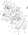
- FIG. 1 shows a fitting 1 according to the invention with a designed as a lock insert 7 lock function part, for illustrative purposes, the rear frame 19 which engages around the fitting element 4 and attachable to the rear frame 19 end cap 22 and the adjoining cover member 23 for inserting a profile cylinder, as in Fig. 6 shown in Fig. 1 not shown.
- the fitting 1 comprises a clamping area 2 (for example in FIG Fig. 2 illustrated) for a door element and has a first fitting element 3 and a second fitting element 4, which each have at least partially an abutment portion 6.1, which includes a voltage applied to the door element intermediate layer 5.
- the lock insert 7.1 is in this case designed in one piece with a third fitting element 8, which is arranged between the fitting elements 3 and 4 and can be connected to these.
- the connection between the third fitting element 8 and the fitting elements 3 and 4 via adjustment elements 9 with a head part 9.1, a connecting part 9.2 and a foot 9.3.
- the adjusting elements 9 are arranged on the connecting part 9.2 slidable in guidings 13 or feasible, which are configured on the fitting element 4.
- the scenes 13 extend between the fitting elements 3 and 4 at least in sections via the free space 6, which is designed as a receiving region between the fitting elements 3 and 4, or via the distance formed between the fitting elements 3 and 4.
- the fitting element 8 via the gate 13 with the fitting element 4 force and / or positively coupled or connectable.
- the Ein-adjusting elements 9 are inserted with the connecting part 9.2 in the slot (slot) designed backdrop 13 and attached to the headboard 9.1 by means of fasteners 11, which are here designed as screws.
- the fastening elements 11 engage through bushings 10 of the fitting element 8 into a respective bore 12 formed in the foot part 9.3 of the adjusting elements 9.
- the bore 12 is preferably designed as an internally threaded bore into which the fastening elements 11 configured as screws engage in a force-locking and / or form-fitting manner , By screwing or tightening the fasteners 11, the adjusting elements 9 are pulled in the direction of the fitting element 8 and jamming in the gate 13. D. h., That on the adjusting elements 9, the fitting element 8 non-positively and / or positively with the fitting element 4, namely in the the fitting element 4 designed backdrop 13 is connected. Since the adjusting elements 9 are displaceably guided or mounted in the slot 13 of the fitting element 4, the fitting elements 3 and 4 of the glass thickness of a door element can be adapted to each other, without the thickness of the intermediate layer 5 having to be changed.
- the material thickness of the intermediate layer 5 always remains constant, so that the distance between the fitting elements 3 and 4 to the door element, and thus the flush Connection of the fitting elements 3 and 4 encompassing frame 19, in particular the flush connection of the edge 20 designed on the edge 21 is maintained on the door element, regardless of the glass thickness of the door element.
- adjusting elements 9 is also connected to the fitting element 8 lock insert 7.1 if necessary, and as far as the installation situation of the fitting 1 according to the invention on a door element, in particular a glass door element allowed, centered to the door leaf thickness of the door element and preferably centered to the glass thickness of the glass door element , In this way, preferably a homogeneous appearance between the lock insert 7.1 and the door panels used for the door element and in particular the glass panes used for the glass door element can be adjusted.
- a lower rosette 24 is attached or attached, the present, as well as the fitting elements 3 and 4 have a cutout in the form of a profile cylinder, the cut-out designed for the lock insert 7.1 a profile cylinder is adjusted.
- the lower rosette 24 engages through the frame 19 and through the end cap 22 and is gripped on the connection cap 22 by a cover element 23, in the present case by a rosette. Also designed as a rosette cover 23 has a cutout for a profile cylinder.
- the length of the profile cylinder is to be selected or adjusted to the length of the door leaf thickness of the door element, in particular to the glass thickness of the clamped between the fitting elements 3 and 4 glass door element.
- the fitting element 8 has a recess 15 for carrying out a functional element of the lock insert 7.1 designed as a mounting module 27, on which, for example, a bolt can be mounted.
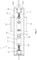
- FIG. 2 shows the in FIG. 1 shown components of a fitting 1 according to the invention in an assembled state in a front view.
- the fitting element 8 is designed in one piece with the lock insert 7 designed as a lock function part 7, which is not visible here due to the representation behind the fitting element 8.
- the fastening elements 11, which connect the fitting element 8 with the adjusting elements 9, are arranged accessible to a user from the outside.
- the fastening elements 11 designed as screws bear their screw head in an end or stop position on the fitting element 8, as a result of which the adjustment elements 9 are at least positively coupled in the scenes 13 of the fitting element 4.
- a mark A configured on the link 13 can be seen.
- the frame 19 overlaps on both sides at least in sections, here in the illustration above and below the fitting element 8. If the clamping area 2 is increased, ie widened the distance between the fitting elements 3 and 4 , thus, the arranged on both sides of the fitting elements 3 and 4 frame 19, each encompass the fitting elements 3 and 4, spaced from each other and thereby reduces the sections covering the edge 20 of the frame 19 on the fitting element 8, so that larger expectant clamping area 2 and a larger area of the fitting element 8 released. By the spacing of the frame 19 with the fitting elements 3 and 4 while a larger area of the mark A is released.
- FIG. 3 is the structure of a fitting 1, as already in the FIG. 1 shown, shown.
- fitting 1 not for receiving a profile cylinder, but for receiving a round cylinder in the fitting 1.
- the cover 23, namely the rosette which rests on the end caps 22, replaced. All other components remain as in the embodiment of the fitting 1 for receiving a profile cylinder, as in FIG. 1 shown, received.
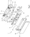
- FIG. 4 is designed as a counter lock box lock function part in a fitting 1 according to the invention.
- a fitting element 8 designed as a plate or striking plate with a recess 15 is arranged between the fitting elements 3 and 4.
- the recess 15 serves, for example, to perform a bolt when clamped to a glass wing door element or to receive the bolt between the fitting elements in the space formed by the glass cutout and by the fitting elements 6 of the designed as a counter lock box fitting 1.
- it requires for the design of the fitting 1 as a counter lock case no other fitting elements 3 and 4 in comparison to the in FIG. 1 and 3
- Only the end caps 22 differ from those in the FIGS. 1 and 3 shown fittings 1, namely the fact that they have no window and attached to the frame 19 end caps 22, the fitting elements 3 and 4 cover full-surface.
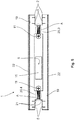
- FIG. 5 shows the configured as a counter lock case fitting 1 FIG. 4 in the assembled state.
- the recess 15 allows a view into the free space 6 designed as a receiving area between the fitting elements 3 and 4.
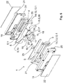
- FIG. 6 shows a fitting 1 according to the invention, which is designed as a corner fitting with a trained as a counter lock box lock function part.
- the fitting elements 3 and 4 are each encompassed by a frame 19, to each of which an end cap 22 is attached. Since the fitting elements 3 and 4 are preferably made of a metal, a metal alloy or also, for example, a plastic metal alloy, an abutment section 6.1, which serves to abut a door element on the fitting elements 3 and 4, comprises an intermediate layer 5 for each fitting element 3 and 4. Since the door element is preferably a glass door element, serves the intermediate layer 5 on the one hand, to prevent a system of metal on glass. On the other hand, the intermediate layers 5 support the damping properties of the fitting 1 according to the invention.
- a holder 25 is provided in each case, which serve for the arrangement, ie for the insertion of exchangeable spacer elements 18 and 18.1.
- the holder 25 is a recess in the form of a blind hole, which serves for the at least positive reception or arrangement of the spacer element 18.
- the holder 25 shown for the fitting element 3 for the spacer element 18.1 is designed as a separate component which engages, for example, in a bore, in particular in a ausgestaltetes on the fitting element blind hole 3 or in this is inserted.
- the holder 25 of the fitting element 3 also has, like the holder 25 of the fitting element 4, a recess which serves for the insertion or for the positive connection with the exchangeable spacer element 18 or 18.1.
- the fitting element 8 is designed as a connecting element 17, which is operatively connected to the holding element 16 and together form an adjusting mechanism, which from a fixing state in a dissolved Condition and vice versa is feasible.
- the connecting element 17 via two Adjustment or fastening elements 11 non-positively and / or positively connected to the support member 16.
- the holding element 16, which is in operative connection as the connecting element 17, is guided in the fitting element 3 and the fitting element 4 in a slotted guide 13, which is configured as a free space 13. 1 in the form of a recess 14, here as a groove.
- the recess 14 or the backdrop 13 configured as a free space 13 is configured parallel to the longitudinal extent of the fitting elements 3 and 4.
- the fitting element 8 configured with the retaining element 16 as a connecting element 17 is advantageously displaceable parallel to the longitudinal extension of the fitting elements with the adjusting element 9 designed as a retaining element 16. Accordingly, the fitting element 8 is also perpendicular to the longitudinal extension of the fitting elements in the space formed as a free space 6 between the fitting elements 3 and 4 movable.
- the fitting element 8, in particular its recess 15, can be adjusted to a latch engaging therein.
- the connecting element 17 is fixed in its position by means of at least non-positive with fitting elements 3 and 4 to the fitting elements 3 and 4 via the holding element 16.
- connection 9 For force and / or positive connection between the designed as a connecting element 17 fitting element 8 and configured as a holding member 16 adjustment 9 serve, as described, fasteners 11 and advantageously screws, which designed by in the fitting element 8, 17 bushings 10 in the form of Holes 12 are performed.
- the passages 10 or holes 12 are advantageously designed as internally threaded holes into which the fasteners 11, after performing through the bushings 10 form fit and / or non-positively engage.
- the holding element 16 and the connecting element 17 are in the present case designed as two interconnected components which comprise a fastening mechanism or the adjusting mechanism, which is presently integrated in both components, namely in the holding element 16 and the connecting element 17.
- a fastening mechanism or the adjusting mechanism which is presently integrated in both components, namely in the holding element 16 and the connecting element 17.
- pin 28 are configured on the connecting part.
- the pins 28 each have a bore 12 through which engage the fasteners 11 which are guided in the bushings 10, and thereby the fitting element 8, namely here, as shown, the connecting element 17 with the holding element 16 force and / or connect positively.
- the head part 16. 1 of the holding element 16 which is perpendicular to the connecting part 16. 2 has at least one and in each case, to the left and right of the connecting part 16. 2, a bearing surface which serves to fix the holding element 16 in the connecting link 3 and 4 as groove 13 or .
- the support surface of the head part 16.1 a corrugation, for example, a diamond-shaped corrugation, which engages in a configured in the scenes 13 corrugation, so that between the Holding element 16 and the fitting elements 3 and 4 in addition to the non-positive connection and a positive connection in the fixing state of the setting or fastening mechanism is formed.
- This embodiment of the support member 16 is of course also in the FIGS. 1 to 5 illustrated embodiments, but in particular then guided in the link 13 connecting part 16.2 of the support member 16, for example, has a corrugation.
- the maximum glass thickness of the clamped in the fitting 1 door element and thus the setting of the clamping area 2 on the sheet thickness of a door member by the bearing surface of the head part 16.2 of the support member 16 is limited, as these, as described above, is guided in the designed as recesses 14 scenes 13 of the fitting elements 3 and 4 and with the recesses 14 via the fastening elements 11, which connect the holding member 16 with the connecting element 17 designed as a fitting element 8, non-positively and / or positively coupled.
- FIG. 7 shows the fitting 1 according to the invention FIG. 6 in assembled state in a frontal view.
- a connecting element 17 fitting element 8 which has a recess 15 for receiving a bolt between the Be-stop elements 3 and 4 with the support member 16 at least partially, here in the figure to the left and to the right, ie displaceable parallel to the fitting elements 3 and 4.
- the fitting 1 embodied here as a counter-lock box is clamped, for example, to a vertical edge of a door element, the recess 15 that is configured in the fitting element 8, 17 can be adjusted in height-variable manner to the engagement of a bolt via the displaceability of the retaining element 16 and the fitting element 8, 17 operatively connected thereto ,
- a counter lock box which is adjustable, ie adjustable in height here in particular on the vertical edge of a door.
- FIG. 8 shows a detailed view of the section A of FIGS. 1 to 5 .
- the detail view A is the designed on the backdrop 13 marker.
- the marking shows indications in the millimeter range, and here preferably information on standardized glass door thicknesses.
- the fitting 1 according to the invention can thus be preset to the known door leaf thicknesses, in particular glass thicknesses of glass door elements.
Description
Die vorliegende Erfindung betrifft einen Beschlag mit einem Schlossfunktionsteil nach dem Oberbegriff von Anspruch 1.The present invention relates to a fitting with a lock function part according to the preamble of
Gattungsbildende Beschläge werden sowohl an Türen als auch an Fenstern montiert und sollen innerhalb eines Beschlagsystems ein einheitliches und optisch vorteilhaftes Erscheinungsbild aufweisen. Insbesondere werden die genannten Beschläge an Türelementen, insbesondere an Glas-türen verbaut, wobei die Beschläge an die jeweiligen Blattstärken bzw. Glas- oder Materialstärken der Türelemente insbesondere der Glastürelemente angepasst werden müssen. Der Aufbau der bekannten Beschläge umfasst zumeist zwei Beschlagelemente, die jeweils einen Anlageabschnitt für das Türelement aufweisen, wobei zwischen den Anlageabschnitten und dem Türelement eine Zwischenlage eingesetzt ist, die zumindest bereichsweise der Kontur der Anlageabschnitte entspricht. Außerhalb der Anlageabschnitte bilden die Beschlagelemente innerhalb eines Ausschnitts des Türelements einen Freiraum, der beispielsweise dazu dient, einen Schlosseinsatz aufzunehmen. Um jedoch Türelemente, insbesondere Glastürelemente verschiedener Stärken, zwischen den bekannten Beschlagelementen aufnehmen zu können, d. h. diese in den Einspannbereich, der durch die Beschlagelemente ausgestaltet ist, einspannen zu können, sind diese so dimensioniert, dass sie in einem Auslieferungszustand, d. h. in einer Ausgangsstellung, lediglich ein Türelement mit einer bestimmten Glasstärke aufnehmen können. Möchte man jedoch ein Glastürelement mit einer anderen Glasstärke aufnehmen, muss bei den bekannten Beschlägen die Zwischenlage verstärkt werden, die zwischen den Beschlagelementen und dem Türelement liegt, um die Differenz der Glasstärke auszugleichen. Dabei ist nachteilig, dass durch die Verstärkung der Zwischenlagen die beidseitig an dem Türelement anliegenden Beschlagelemente von dem Türelement abrücken. Mit den Beschlagelementen rücken auch Deckel- oder Abdeckelemente, wie beispielsweise Kappen, die die Beschlagelemente umgreifen bzw. auf diese aufgesetzt sind, beidseitig von dem Türelement ab. Entsprechend entsteht beidseitig des Türelements, nämlich zwischen den Flächen des Türelements und dem Deckel- bzw. Abdeckelement, automatisch ein Spalt. Möchte man diese Spaltbildung verhindern, muss das Deckel- bzw. Ab-deckelement beidseitig des Türelements durch ein tiefergezogenes Deckel- bzw. Abdeckelement ausgetauscht werden, welches dann den von der verstärkten Zwischenlage gebildeten Spalt überdeckt. Dies bedeutet zum einen, dass die bekannten Beschläge neben unterschiedlich starken Zwischenlagen mit unterschiedlichen Deckel- bzw. Abdeckelementen ausgeliefert werden müssen, um diese an unterschiedlich starke Glastürelemente bzw. Türblattstärken anpassen zu können, und zum anderen ist nachteilhaft, dass die Bautiefe der bekannten Beschläge beidseitig des Türelements vergrößert wird. Zudem ist nicht auszuschließen, dass bei stark ausgebildeten Zwischenlagen die Klemmung des Beschlages an dem Türelement so stark verringert wird, dass dessen Belastbarkeit bzw. dessen Stabilität darunter leidet.Generic fittings are mounted both on doors and windows and should have a uniform and visually advantageous appearance within a fitting system. In particular, the said fittings are installed on door elements, in particular on glass doors, wherein the fittings must be adapted to the respective sheet thicknesses or glass or material thicknesses of the door elements, in particular the glass door elements. The structure of the known fittings usually comprises two fitting elements, each having a contact portion for the door element, wherein between the contact portions and the door element, an intermediate layer is used, which at least partially corresponds to the contour of the contact sections. Outside the contact sections, the fitting elements within a section of the door element form a free space which serves, for example, to receive a lock insert. However, in order to be able to receive door elements, in particular glass door elements of different thicknesses, between the known fitting elements, ie to be able to clamp them in the clamping area, which is configured by the fitting elements, these are dimensioned such that in a delivery state, ie in a starting position, can only accommodate a door element with a certain glass thickness. However, if you want to record a glass door element with a different glass thickness, the intermediate layer must be reinforced in the known fittings, which between the Fitting elements and the door element is located to compensate for the difference in the glass thickness. It is disadvantageous that move away by the reinforcement of the intermediate layers on both sides of the door element fitting elements of the door element. With the fitting elements also cover or cover elements, such as caps, which surround the fitting elements or are placed on this, move from both sides of the door element. Accordingly arises on both sides of the door element, namely between the surfaces of the door member and the cover or cover, automatically a gap. If you want to prevent this gap, the cover or Ab cover element must be replaced on both sides of the door element by a deeper drawn cover or cover, which then covers the gap formed by the reinforced intermediate layer. This means, on the one hand, that the known fittings, in addition to different thicknesses of liners, must be delivered with different cover or cover elements in order to be able to adapt them to glass door elements or door leaf thicknesses having different thicknesses, and, secondly, it is disadvantageous that the overall depth of the known fittings is double-sided of the door element is increased. In addition, it can not be ruled out that in strongly formed intermediate layers, the clamping of the fitting on the door element is so greatly reduced that its capacity or its stability suffers.
Es ist daher die Aufgabe der vorliegenden Erfindung, die voranstehend beschriebenen Nachteile des Standes der Technik zumindest teilweise zu beheben. Insbesondere ist es die Aufgabe der vorliegenden Erfindung, einen Beschlag zur Verfügung zu stellen, der eine erweiterte Einstellmöglichkeit, nämlich die Einstellung auf verschiedene Türelemente mit unterschiedlichen Türblattstärken, insbesondere mit unterschiedlichen Glasstärken erlaubt.It is therefore the object of the present invention to at least partially overcome the above-described disadvantages of the prior art. In particular, it is the object of the present invention to provide a fitting which allows an extended setting possibility, namely the adjustment to different door elements with different door leaf thicknesses, in particular with different glass thicknesses.
Die voranstehende Aufgabe wird durch einen Beschlag mit den Merkmalen des Anspruchs 1 gelöst. Weitere Vorteile, Merkmale und Details der Erfindung ergeben sich aus den Unteransprüchen, der Beschreibung und den Zeichnungen.The above object is achieved by a fitting with the features of
Der Beschlag gemäß Anspruch 1 mit einem Schlossfunktionsteil, insbesondere Schlosseinsatz oder Schlosskasten oder Gegenschlosskasten, mit einem Einspannbereich für ein Türelement, insbesondere für ein Glastürelement, aufweisend ein erstes Beschlagelement und ein zweites Beschlagelement, welche jeweils zumindest bereichsweise einen Anlageabschnitt aufweisen, der eine mit dem Türelement kontaktierbare Zwischenlage umfasst, wobei die Beschlagelemente den Einspannbereich begrenzen, und wobei das Schlossfunktionsteil ein drittes Beschlagelement aufweist, das zwischen den Beschlagelementen angeordnet ist, schließt die technische Lehre ein, dass zwischen den Beschlagelementen ein Einstellmechanismus vorgesehen ist, mit dem eine Positionsausrichtung des Schlossfunktionsteils bezüglich der Beschlagelemente ausführbar ist, wobei der Einstellmechanismus derart zwischen den Beschlagelementen ausgeführt ist, dass eine Bewegung des Schlossfunktionsteils orthogonal zur Längserstreckung der Beschlagelemente zur Positionsausrichtung durchführbar ist oder eine Bewegung des Schlossfunktionsteils parallel zur Längserstreckung der Beschlagelemente zur Positionsausrichtung durchführbar ist, wobei der Einstellmechanismus mindestens eine am Beschlagelement angeordnete Kulisse aufweist, entlang dieser Kulisse das Schlossfunktionsteil über ein Einstellelement bewegbar ist. Diese Lösung bietet den Vorteil, dass unter Aufrechterhaltung der Funktion des Beschlages durch den Einstellmechanismus, eine Positionsausrichtung des Schlossfunktionsteils innerhalb des Beschlages ermöglicht wird, wobei der Abstand der Beschlagelemente auf die Glasstärke eines in dem Beschlag eingespannten Türelements verändert werden kann, ohne dass dabei die Beschlagelemente durch eine stärker werdende Zwischenlage von dem Türelement abrücken. D. h., dass der Abstand der Beschlagelemente zu dem zwischen den Beschlagelementen in dem Einspannbereich eingespannten Türelement unabhängig von der Glasstärke bzw. der Türblattstärke des Türelements immer konstant bleibt.The fitting according to
Daraus ergibt sich der Vorteil, dass ein beispielsweise jeweils die Beschlagelemente umgreifender Rahmen oder eine Kappe, die als Deckel- bzw. Abdeckelement auf die Beschlagelemente aufgesetzt wird, immer an dem Glastürelement unabhängig von dessen Glasstärke anliegt. Insofern kann durch die Ausgestaltung des erfindungsgemäßen Beschlages mit einem Einstellmechanismus, der eine Positionsausrichtung des Schlossfunktionsteils ermöglicht, eine Spaltbildung zwischen den Beschlagelementen und dem Türelement, unabhängig von der Türblatt- bzw. Glasstärke des Türelements unterbunden werden. Das bedeutet auch automatisch, dass beidseitig des Türelements die Bautiefe des erfindungsgemäßen Beschlages unabhängig von der Türblatt- bzw. Glasstärke immer gleich ist. Da das Schlossfunktionsteil ein drittes Beschlagelement aufweist, kann die Funktion des Beschlages variabel angepasst werden. So kann beispielsweise das dritte Beschlagelement ein Schließblech sein, welches über den Einstellmechanismus in seiner Positionierung ausgerichtet wird und welches das als Gegenschlosskasten ausgestaltete Schlossfunktionsteil bildet.This results in the advantage that a, for example, the fitting elements encompassing frame or a cap, which is placed as a cover or cover on the fitting elements, always rests against the glass door element regardless of its glass thickness. In this respect, a gap formation between the fitting elements and the door element, regardless of the door leaf or glass thickness of the door element can be prevented by the configuration of the fitting according to the invention with an adjustment mechanism that allows a position alignment of the lock function part. This also automatically means that the depth of the fitting according to the invention is always the same on both sides of the door element, regardless of the door leaf or glass thickness. Since the lock function part has a third fitting element, the function of the fitting can be variably adjusted. For example, the third fitting element may be a striking plate, which is aligned in its positioning via the adjustment mechanism and which forms the lock function part designed as a counter-lock case.
Da über den Einstellmechanismus der erfindungsgemäße Beschlag variabel an die Türblatt- bzw. Glasstärke eines darin geklemmten Türelements einstellbar ist, kann in vorteilhafter Weise die Stärke der Zwischenlage, die zwischen den Beschlagelementen und dem Türelement, d. h. im Klemm- bzw. Einspannbereich des erfindungsgemäßen Beschlages, angeordnet ist, immer konstant bleiben. Insofern kann in vorteilhafter Weise, unabhängig von dem mit dem erfindungsgemäßen Beschlag geklemmten Türelement mit variabler Stärke, eine immer gleichbleibende Stabilität des Beschlages gewährleistet werden. Erfindungsgemäß weist der Einstellmechanismus ein Einstellelement oder ein als Einstellelement ausgeführtes Halteelement auf, dass derart zwischen den Beschlagelementen angeordnet ist, dass eine Bewegung des Schlossfunktionsteils orthogonal zur Längserstreckung der Beschlagelemente zur Positionsausrichtung durchführbar ist oder eine Bewegung des Schlossfunktionsteils parallel zur Längserstreckung der Beschlagelemente zur Positionsausrichtung durchführbar ist. Um eine Positionsausrichtung des Schlossfunktionsteils parallel zur Längserstreckung der Beschlagelemente durchzuführen, weist zumindest ein Beschlagelement und in bevorzugter Weise beide Beschlagelemente einen Freiraum auf, in dem das Einstellelement oder das Halteelement, welches ein Bauteil des Einstellmechanismus ist, bewegbar ist. Als Freiraum soll im Sinne der Anmeldung beispielsweise eine Ausnehmung, ein Schlitz oder eine Nut verstanden werden, die in Längserstreckung in zumindest einem der Beschlagelemente verläuft. Als Freiraum wird aber auch im Sinne der vorliegenden Erfindung ein zwischen den beiden Beschlagelementen gebildeter Abstand verstanden, der es ermöglicht das Einstellelement oder das Halteelement, welche vorteilhaft ein Kopfteil, ein Verbindungsteil und optional ein Fußteil aufweisen, mit dem Verbindungsteil zwischen den Beschlag-elementen zu bewegen. Im Gegensatz dazu dient der als Ausnehmung ausgestaltete Freiraum, der in Längserstreckung der Beschlagelemente verläuft, dazu, um das Halteelement mit seinem Kopfteil beweglich zu lagern bzw. das Halteelement über das Kopfteil kraft- und/oder formschlüssig mit zumindest einem Beschlagelement zu koppeln.Since the fitting according to the invention can variably be adjusted to the door leaf or glass thickness of a door element clamped therein, the thickness of the intermediate layer between the fitting elements and the door element, ie in the clamping or clamping region of the fitting according to the invention, can be advantageously determined. is arranged, always stay constant. In this respect, regardless of the clamped with the fitting according to the invention door element with variable thickness, an always stable stability of the fitting can be ensured in an advantageous manner. According to the invention, the adjusting mechanism has an adjusting element or a holding element designed as an adjusting element, which is arranged between the fitting elements such that a movement of the lock operating part orthogonal to the longitudinal extension of the fitting elements for position alignment is feasible or a movement of the lock function part parallel to the longitudinal extension of the fitting elements for position alignment is feasible , In order to perform a positional alignment of the lock function part parallel to the longitudinal extension of the fitting elements, at least one fitting element and preferably both fitting elements have a free space in which the adjustment element or the holding element, which is a component of the adjustment mechanism, is movable. As a free space is to be understood in the context of the application, for example, a recess, a slot or a groove extending in the longitudinal extent in at least one of the fitting elements. As a free space but is also understood in the context of the present invention formed between the two fitting elements distance, which allows the adjustment or the holding element, which advantageously have a head part, a connecting part and optionally a foot, with the connecting part between the fitting elements move. In contrast, designed as a recess clearance, which extends in the longitudinal extension of the fitting elements, is used to store the holding element with its head part movable or the holding element via the head part non-positively and / or positively coupled with at least one fitting element.
In vorteilhafter Weise ist das Halteelement als L-Profil mit einem Kopf- und einem Verbindungsteil ausgestaltet, vorzugsweise in Form von zwei im Wesentlichen orthogonal zueinander stehenden Flächen, wobei der Kopfteil in dem als Nut, Schlitz oder Ausnehmung ausgestalteten Freiraum in einem der Beschlagelemente im gelösten Zustand des Einstellmechanismus beweglich gelagert und im Fixierungszustand des Einstellmechanismus klemmend in der Ausnehmung wirkt und das Verbindungsteil in Wirkverbindung mit dem Verbindungselement steht. Weisen jeweils beide Beschlagelemente einen als Nut, Schlitz oder Ausnehmung ausgestalteten Freiraum auf, ist das Kopfteil des Halteelements bzw. das Halteelement in vorteilhafter Weise als T-Profil ausgestaltet, um das Halteelement in beiden Ausnehmungen der Beschlagelemente beweglich zu lagern bzw. zu klemmen. Durch Überführung des Einstellmechanismus aus seinem gelösten Zustand in den Fixierungszustand bietet das als T-Profil ausgestaltete Halteelement beidseitig, d. h. in beiden als Nut, Schlitz oder Ausnehmung ausgestalteten Freiräumen der Beschlagelemente zumindest abschnittsweise eine Auflagefläche, die zur kraft- und/oder formschlüssigen Verbindung zwischen dem Halteelement und den Beschlagelementen dient, d. h. im Fixierungszustand des Einstellmechanismus das Kopfteil klemmend in beiden Nuten, Schlitzen oder Ausnehmungen wirkt. Im Gegensatz zu dem als L-Profil ausgestalteten Halteelement klemmt das als T-Profil ausgestaltete Halteelement gleichmäßig auf beiden Seiten des Eckbeschlags, nämlich an beiden Beschlagelementen. Dadurch kann im Gegensatz zu dem als L-Profil ausgestalteten Halteelement mit dem als T-Profil ausgestalteten Halteelement ein stabilerer Kraft- und/oder Formschluss, d. h. eine verbesserte Klemmung zwischen dem Halteelement und den Beschlagelementen erreicht werden. Wie auch bereits für das als L-Profil ausgestaltete Halteelement beschrieben, wird auch bei dem als T-Profil ausgestalteten Halteelement über ein Verbindungsteil das Verbindungselement mit dem Halteelement verbunden.Advantageously, the holding element is designed as an L-profile with a head and a connecting part, preferably in the form of two substantially mutually orthogonal surfaces, wherein the head part in the designed as a groove, slot or recess space movably mounted in one of the fitting elements in the released state of the adjustment mechanism and in the fixing state of the adjustment mechanism acts in a clamping manner in the recess and the connecting part is in operative connection with the connecting element. If in each case both fitting elements have a free space configured as a groove, slot or recess, the head part of the holding element or the holding element is configured advantageously as a T-shaped profile in order to movably support or clamp the holding element in both recesses of the fitting elements. By transferring the adjustment mechanism from its released state into the fixing state, the retaining element designed as a T-profile offers on both sides, ie at least in sections, a support surface in both free-spaces of the fitting elements designed as a groove, slot or recess, which provides a non-positive and / or positive connection between the Holding element and the fitting elements is used, that is, in the fixing state of the adjustment mechanism, the head part clampingly acts in two grooves, slots or recesses. In contrast to the designed as an L-profile retaining element designed as a T-shaped retaining element clamps evenly on both sides of the corner fitting, namely on both fitting elements. As a result, in contrast to the retaining element designed as an L-profile with the holding element designed as a T-profile, a more stable force and / or positive connection, ie an improved clamping between the retaining element and the fitting elements, can be achieved. As has already been described for the retaining element designed as an L-profile, the connecting element is also connected to the retaining element via a connecting part in the case of the holding element designed as a T-profile.
In bevorzugter Weise weist das Einstellelement ein Kopfteil, ein Verbindungsteil und ein Fußteil auf, wobei über zumindest ein Befestigungselement das Einstellelement über das Fußteil mit dem dritten Beschlagelement verbunden wird. Dabei sind vorteilhaft das Kopfteil und das Verbindungsteil senkrecht zueinander ausgestaltet. Dagegen ist vorteilhaft das Fußteil parallel zu dem Kopfteil ausgestaltet und bildet in bevorzugter Weise mit dem Kopfteil und dem Verbindungsteil ein monolithisches und/oder einstückiges Bauteil.In a preferred manner, the adjusting element has a head part, a connecting part and a foot part, wherein the adjusting element is connected to the third fitting element via the foot part via at least one fastening element. Advantageously, the head part and the connecting part are configured perpendicular to each other. In contrast, the foot part is advantageously designed parallel to the head part and forms in a preferred manner with the head part and the connecting part a monolithic and / or one-piece component.
In besonders vorteilhafter Weise handelt es sich bei dem Halteelement und dem mit dem Halteelement über das Verbindungsteil in Wirkverbindung stehende Verbindungselement, das beispielsweise als Schlossfunktionsteil in Form eines Gegenschlosskastens ausgestaltet ist, um zwei miteinander verbundene Bauteile des Beschlages. Diese miteinander verbundenen Bauteile bilden bevorzugt den Einstellmechanismus, der in vorteilhafter Weise an beiden Bauteilen, nämlich am Halteelement sowie am Verbindungselement integriert ist, und der zwischen dem gelösten Zustand und dem Fixierungszustand überführbar ist, wobei im gelösten Zustand das Halteelement an den Beschlagelementen verschiebbar ist und im Fixierungszustand zumindest kraft- oder formschlüssig an zumindest einem Beschlagelement befestigt ist. Demzufolge dient der am Halteelement und am Verbindungselement ausgebildete Einstellmechanismus dazu, das Halteelement und das mit dem Halteelement verbundene Verbindungselement relativ zu den Beschlagelementen und insbesondere relativ zu der Längserstreckung der Beschlagelemente zu verschieben. Darüber hinaus dient der Einstellmechanismus dazu, den Beschlag und insbesondere das als Schlossfunktionsteil ausgestaltete Verbindungselement zu positionieren und zu fixieren, nämlich das Halteelement über den Einstellmechanismus an zumindest einem der Beschlagelemente zumindest kraftschlüssig oder formschlüssig zu koppeln.In a particularly advantageous manner, the holding element and the connecting element which is in operative connection with the holding element via the connecting element, which is designed, for example, as a lock operating part in the form of a counter-lock box, are two interconnected components of the fitting. These interconnected components preferably form the adjustment mechanism, which is advantageously integrated on both components, namely on the holding element and on the connecting element, and which can be transferred between the released state and the fixing state, wherein in the released state, the holding element is displaceable on the fitting elements and fixed in the fixing state at least non-positively or positively on at least one fitting element. Accordingly, the adjusting mechanism formed on the holding element and on the connecting element serves to displace the holding element and the connecting element connected to the holding element relative to the fitting elements and in particular relative to the longitudinal extension of the fitting elements. In addition, the adjustment mechanism serves to position and fix the fitting, and in particular the connecting element designed as a lock function part, namely the retaining element via the adjustment mechanism to couple at least one of the fitting elements at least positively or positively.
Um eine Wirkverbindung zwischen dem Halteelement und dem Verbindungselement herzustellen, d. h. um eine Variante des erfindungsgemäßen Einstellmechanismus auszubilden, sind das Halteelement und das Verbindungselement besonders vorteilhaft über zumindest ein Befestigungselement kraft- und/oder formschlüssig miteinander verbunden. Bei dem Befestigungselement zwischen dem Halteelement und dem Verbindungselement kann es sich beispielsweise um eine Schraube, wie z. B. eine Madenschraube, handeln, die das Halteelement und das Verbindungselement miteinander verbindet. Besonders vorteilhaft sind wenigstens zwei Befestigungselemente vorgesehen, die das Halteelement mit dem Verbindungselement verbinden. Die kraft- und/oder formschlüssige Verbindung zwischen dem Halteelement und dem Verbindungselement, d. h. die Überführung des Einstellmechanismus aus dem gelösten Zustand in den Fixierungszustand dient zudem in vorteilhafter Weise dazu, das Halteelement an dem Beschlagelement festzulegen. Dazu weist das Beschlagelement bevorzugt einen Freiraum als Führung auf, beispielsweise in Form einer Ausnehmung, einer Nut oder einer Schiene, an bzw. in denen das Halteelement geführt wird bzw. beweglich gelagert ist. Der Freiraum in dem Beschlagelement ist dabei vorteilhaft so ausgestaltet, dass das Halteelement in Längserstreckung des Beschlagelements verschiebbar bzw. führbar ist.In order to establish an operative connection between the retaining element and the connecting element, d. H. In order to form a variant of the adjustment mechanism according to the invention, the holding element and the connecting element are particularly advantageous connected by at least one fastening element non-positively and / or positively. In the fastener between the support member and the connecting element may be, for example, a screw, such. B. a grub screw act, which connects the holding element and the connecting element together. Particularly advantageous at least two fastening elements are provided, which connect the holding element with the connecting element. The non-positive and / or positive connection between the holding element and the connecting element, d. H. the transfer of the adjustment mechanism from the released state into the fixing state also advantageously serves to fix the retaining element to the fitting element. For this purpose, the fitting element preferably has a free space as a guide, for example in the form of a recess, a groove or a rail, on or in which the holding element is guided or is movably mounted. The free space in the fitting element is advantageously designed so that the holding element in the longitudinal extent of the fitting element is displaceable or feasible.
Um eine Bewegung des Schlossfunktionsteils orthogonal zur Längserstreckung der Beschlagelemente durchzuführen, weist erfindungsgemäß der Einstellmechanismus mindestens eine am Beschlagelement angeordnete Kulisse auf, an der das Schlossfunktionsteil über das Einstellelement bewegbar ist. Die Kulisse erstreckt sich dabei bevorzugt zwischen den Beschlagelementen, nämlich in den Abstand zwischen den Beschlagelementen. In bevorzugter Weise sind zwei parallel zueinander liegende Kulissen an dem Beschlag angeordnet, wobei die Kulissen bevorzugt an einem oder noch bevorzugter an beiden Beschlagelementen ausgebildet sind und das Schlossfunktionsteil über zwei Einstellelemente in den beiden Kulissen bewegbar ist. In vorteilhafter Weise erstreckt sich die Kulisse bevorzugt zumindest abschnittsweise zwischen den Beschlagelementen, d. h. zumindest soweit, dass das Einstellelement auch noch dann an der Kulisse führ- und klemmbar ist, wenn die Türblattstärke bzw. die Glasstärke des zwischen den Beschlagelementen eingespannten Türelements zwischen ungefähr 6 mm und 25 mm, bevorzugt zwischen 7 mm und 22 mm, und noch bevorzugter zwischen 8 mm und 17 mm liegt.In order to carry out a movement of the lock function part orthogonal to the longitudinal extent of the fitting elements, according to the invention the adjustment mechanism has at least one link arranged on the fitting element, on which the lock function part can be moved via the adjustment element. The The backdrop preferably extends between the fitting elements, namely in the distance between the fitting elements. Preferably, two mutually parallel scenes are arranged on the fitting, wherein the scenes are preferably formed on one or more preferably on both fitting elements and the lock function part via two adjusting elements in the two scenes is movable. Advantageously, the link preferably extends at least in sections between the fitting elements, ie at least to the extent that the adjustment even at the gate guide and is clamped when the door leaf thickness or the glass thickness of the clamped between the door elements between about 6 mm and 25 mm, preferably between 7 mm and 22 mm, and more preferably between 8 mm and 17 mm.
Vorteilhaft bildet die Kulisse mit mindestens einem Beschlagelement ein gemeinsames Bauteil. Dabei sind die Kulisse und das Beschlagelement bevorzugt einstückig und/oder als ein monolithisches Bauteil ausgebildet. Als monolithisches Bauteil soll dabei ein beispielsweise im Spritzgussverfahren aus einer oder mehreren verschiedenen Komponenten hergestelltes Bauteil verstanden werden. Als einstückiges Bauteil kann aber auch ein aus einem Material hergestelltes Bauteil verstanden werden, das beispielsweise durch Bearbeitung eines Metallblocks aus dem Metallblock herausgefräst wird. Ein gemeinsames Bauteil ist vorzugsweise auch so zu verstehen, dass die Kulisse und das Beschlagelement als Einzelteile ausgestaltet sind, die als gemeinsames Bauteil, nämlich als Beschlagelement in einem vormontierten Zustand mit Kulisse bereitgestellt werden.Advantageously, the backdrop with at least one fitting element forms a common component. The link and the fitting element are preferably in one piece and / or formed as a monolithic component. In this case, a monolithic component is understood to be a component produced, for example, by injection molding from one or more different components. As a one-piece component but can also be understood a made of a material component which is milled out, for example, by machining a metal block from the metal block. A common component is preferably also to be understood that the link and the fitting element are designed as individual parts, which are provided as a common component, namely as a fitting element in a preassembled state with backdrop.
Das Einstellelement ist bevorzugt beweglich in der Kulisse gelagert und lässt sich vorteilhafterweise stufenlos entlang der Erstreckung der Kulisse in dem Freiraum bewegen, der als Abstand zwischen den Beschlagelementen ausgebildet ist. In vorteilhafter Weise kann dabei die Positionsausrichtung des Schlossfunktionsteils über den gesamten durch die Beschlag-elemente als Freiraum gebildeten Abstand erfolgen. Insbesondere unterstützt diese Ausgestaltung des erfindungsgemäßen Beschlages eine kompakte Bauweise und eine einheitliche Bautiefe unabhängig von der Materialstärke des zwischen den Beschlagelementen geklemmten Türelements.The adjustment is preferably movably mounted in the backdrop and can be advantageously infinitely along the extension of the backdrop move in the free space, which is formed as a distance between the fitting elements. In this case, the position alignment of the lock function part can advantageously take place over the entire distance formed by the fitting elements as clearance. In particular, this embodiment of the fitting according to the invention supports a compact design and a uniform overall depth regardless of the material thickness of the clamped between the fitting elements door element.
In vorteilhafter Weise weist die Kulisse einen Freiraum in Form einer als Schlitz oder einer Nut ausgestalteten Ausnehmung auf, durch den oder in dem das Halteelement beweglich zwischen den Beschlagelementen ist. Dabei ist in vorteilhafter Weise das Halteelement abschnittsweise als L-Profil oder als T- ausgestaltet, vorzugsweise in Form von zwei im Wesentlichen orthogonal zueinander stehenden Flächen, die ein Kopfteil und ein Verbindungsteils bilden, wobei das Verbindungsteil in dem als Nut, Schlitz oder Ausnehmung ausgestalteten Freiraum in der Kulisse im gelösten Zustand des Einstellmechanismus beweglich gelagert und im Fixierungszustand des Einstellmechanismus klemmend in der Ausnehmung wirkt.Advantageously, the gate has a free space in the form of a recess designed as a slot or a groove through which or in which the holding element is movable between the fitting elements. In this case, the holding element is advantageously configured in sections as an L-profile or T-shaped, preferably in the form of two substantially mutually orthogonal surfaces forming a head part and a connecting part, wherein the connecting part configured in the groove, slot or recess Free space in the scenery movably mounted in the released state of the adjustment mechanism and acts in the recess in the fixing state of the adjustment clamped.
Vorteilhaft ist das Einstellelement oder das Halteelement am Schlossfunktionsteil und/oder an dem dritten Beschlagelement befestigt. Die Befestigung erfolgt entweder über das an dem Einstellelement oder an dem Halteelement ausgebildete Verbindungsteil oder an einem mit dem Verbindungsteil verbundenen Fußteil, wobei in vorteilhafter Weise das Fußteil, das Verbindungsteil und das Kopfteil des Einstell- bzw. des Halteelements als ein gemeinsames, monolithisches und/oder einstückiges Bauteil ausgestaltet sind. Als monolithisches Bauteil soll auch hierbei ein beispielsweise im Spritzgussverfahren aus einer oder mehreren verschiedenen Komponenten hergestelltes Bauteil verstanden werden. Als einstückiges Bauteil kann aber auch ein aus einem Material hergestelltes Bauteil verstanden werden, das beispielsweise durch Bearbeitung eines Metallblocks aus dem Metallblock herausgefräst wird. Ein gemeinsames Bauteil ist vorzugsweise auch so zu verstehen, dass das Kopfteil, das Verbindungsteil und/oder das Fußteil als Einzelteile ausgestaltet sind, die als gemeinsames Bauteil, nämlich als Einstellelement bzw. als Halteelement in einem vormontierten Zustand mit Kulisse bereitgestellt werden.The adjusting element or the retaining element is advantageously fastened to the lock functional part and / or to the third fitting element. The fastening takes place either via the connecting part formed on the adjusting element or on the retaining element or on a foot part connected to the connecting part, advantageously the foot part, the connecting part and the head part of the adjusting or retaining element being a common, monolithic and / or or one-piece component are designed. As a monolithic component in this case, for example, by injection molding of a or understood component made of several different components. As a one-piece component but can also be understood a made of a material component which is milled out, for example, by machining a metal block from the metal block. A common component is preferably also to be understood that the head part, the connecting part and / or the foot part are designed as individual parts, which are provided as a common component, namely as an adjustment or as a holding element in a preassembled state with backdrop.
Zur Einstellung des Einstellmechanismus, insbesondere zur Überführung des Einstellmechanismus aus dem gelösten Zustand in den Fixierungszustand und umgekehrt, ist ein Befestigungselement bevorzugt von außen zugänglich für einen Benutzer angeordnet, beispielsweise an einem als Schließblech ausgestalteten dritten Beschlagelement für ein als Gegenschlosskasten ausgestaltetes Schlossfunktionsteil. Da das dritte Beschlag-element in Wirkverbindung mit dem Einstellelement oder dem Halteelement steht, das zwischen dem ersten und dem zweiten Beschlagelement in der Kulisse geführt wird, und das Einstellelement oder das Halteelement damit schwer zugänglich ist, kann vorteilhaft über die von außen am dritten Beschlagelement zugänglichen Befestigungselemente vorteilhaft der Einstellmechanismus bedient werden.To set the adjustment mechanism, in particular for the transfer of the adjustment mechanism from the released state to the fixed state and vice versa, a fastener is preferably accessible from the outside accessible to a user, for example, on a designed as a striking plate third fitting element designed as a counter lock box lock function part. Since the third fitting element is in operative connection with the adjusting element or the holding element, which is guided between the first and the second fitting element in the gate, and the adjustment or the holding element is thus difficult to access, can be advantageous over the outside of the third fitting element accessible fasteners advantageously the adjustment mechanism can be operated.
Damit das als Halteelement ausgestaltete Einstellelement eine Hubbewegung durch die vorzugsweise von außen zugänglich für den Benutzer angeordneten Befestigungselemente durchführen kann, und um den Einstellmechanismus integriert am Halteelement auszubilden, weist das Halteelement wenigstens eine Bohrung auf, in die das Befestigungselement im Fixierungszustand zumindest teilweise eingreift, wodurch eine erhöhte Klemmung zwischen dem Halteelement und der Ausnehmung wirkt. Im losgelösten Zustand greift das Befestigungselement vorzugsweise weniger weit in die Bohrung ein oder befindet sich beabstandet zur Bohrung, so dass die Klemmung geringer ist oder die Klemmung nahezu aufgehoben ist.So that the adjusting element designed as a holding element can perform a lifting movement through the fastening elements, which are preferably accessible to the user from outside, and to form the adjusting mechanism integrally on the holding element, the holding element has at least one bore into which the fastening element at least partially engages in the fixing state, whereby an increased clamping between the retaining element and the recess acts. In the detached state, the fastener preferably engages less far into the bore or is spaced from the bore, so that the clamping is less or the clamping is almost canceled.
Damit das Befestigungselement von außen beispielsweise am Schließblech zugänglich ist, weist das dritte Beschlagelement wenigstens eine Durchführung auf, durch die das Befestigungselement sich bis zur Bohrung erstreckt, und die vorteilhaft als Innengewindebohrung ausgestaltet ist.Thus, the fastener is accessible from the outside, for example, on the strike plate, the third fitting element has at least one passage through which the fastening element extends to the bore, and which is advantageously designed as an internal threaded bore.
Da das Innengewinde der Durchführung als Widerlager für das Befestigungselement dient, das vorzugsweise eine Schraube ist, wird das Einstellelement oder das Halteelement mit Vortrieb des Befestigungselements in entgegengesetzter Richtung zum Vortrieb des Befestigungselements bewegt. Dabei gelangt insbesondere das in der Ausnehmung der Kulisse geführte Einstell- bzw. Halteelement zur kraftschlüssigen Anlage an die Ausnehmung. Durch Anziehen des Befestigungselements gelangt dabei der Kopf, hier bevorzugt der Schraubenkopf, zur Anlage an die in dem dritten Beschlagelement ausgestaltete Durchführung, wodurch das Einstell- bzw. Halteelement relativ zu dem dritten Beschlagelement hin bewegt wird bzw. das Einstell- oder das Halteelement relativ zu der Kulisse bewegt wird. Durch die Bewegung des Einstell- bzw. Halteelements relativ zu der Kulisse wird das Einstell- bzw. Halteelement in bevorzugter Weise kraft- und/oder formschlüssig mit der Kulisse gekoppelt.Since the internal thread of the bushing serves as an abutment for the fastening element, which is preferably a screw, the adjusting element or the retaining element is moved in the opposite direction to the propulsion of the fastening element with propulsion of the fastening element. In particular, the adjustment or holding element, guided in the recess of the slotted guide, reaches the recess for non-positive engagement. By tightening the fastener while the head, here preferably the screw head, comes to rest against the configured in the third fitting element implementation, whereby the adjusting or holding element is moved relative to the third fitting element or the setting or the holding element relative to the backdrop is moved. Due to the movement of the adjusting or holding element relative to the backdrop, the adjusting or holding element is coupled in a preferred manner non-positively and / or positively with the backdrop.
In vorteilhafter Weise sind das dritte Beschlagelement und das Schlossfunktionsteil als ein monolithisches und/oder einstückiges Bauteil ausgestaltet. Als monolithisches Bauteil soll auch hier ein beispielsweise im Spritzgussverfahren aus einer oder mehreren verschiedenen Komponenten hergestelltes Bauteil verstanden werden. Als einstückiges Bauteil kann auch ein aus einem Material hergestelltes Bauteil verstanden werden, das beispielsweise durch Bearbeitung eines Materialblocks, beispielsweise ein Metallblock, aus dem Materialblock herausgefräst wird. Ein gemeinsames Bauteil ist vorzugsweise auch so zu verstehen, dass das Beschlagelement und das Schlossfunktionsteil Einzelteile sind, die als gemeinsames Bauteil in einem vormontierten Zustand bereitgestellt werden.Advantageously, the third fitting element and the lock function part as a monolithic and / or one-piece component designed. As a monolithic component, a component produced, for example, by injection molding from one or more different components should also be understood here. As a one-piece component can also be understood a component made of a material which is milled out of the block of material, for example by machining a block of material, for example a metal block. A common component is preferably also to be understood that the fitting element and the lock function part are individual parts that are provided as a common component in a preassembled state.
Um die Klemmung, d. h. die Reibung zwischen dem Halteelement, hier insbesondere der Auflagefläche des Halteelements und dem als Ausnehmung ausgestalteten Freiraum, hier insbesondere der Kulisse, zu erhöhen, weist das Halteelement im Bereich der Auflagefläche des Verbindungsteils bevorzugt ein Profil auf, welches beispielsweise eine Riffelung sein kann. Das Profil der Auflagefläche ist dabei so ausgestaltet, dass die Klemmung bzw. die Reibung zwischen dem Halteelement und der Ausnehmung neben einem Kraftschluss einen Formschluss gewährleistet.To the clamping, d. H. the friction between the holding element, here in particular the bearing surface of the holding element and the space designed as a recess, in particular the link, to increase, the holding element in the region of the bearing surface of the connecting part preferably has a profile, which may be, for example, a corrugation. The profile of the support surface is designed so that the clamping or the friction between the holding element and the recess next to a frictional connection ensures a positive connection.
Für die Verwendung des erfindungsgemäßen Beschlages zur Aufnahme eines Schlosseinsatzes oder als Gegenschlosskasten weist das zwischen dem ersten und dem zweiten Beschlagelement angeordnete Beschlagelement zumindest eine Aussparung auf, die zum Durchgriff und/oder Eingriff eines Funktionselementes eines Schlosses ausgestaltet ist. Als Funktionselement eines Schlosses kann dabei beispielsweise ein Riegel verstanden werden, der in die Aussparung des Beschlagelementes greift, welches in einem erfindungsgemäßen Beschlag angeordnet ist, der als Gegenschlosskasten ausgestaltet und der zur Klemmung an beispielsweise einer zweiflügligen Glastür dient. Wenn ein Schlosseinsatz in dem erfindungsgemäßen Beschlag im Aufnahmebereich zwischen den Beschlagelementen aufgenommen ist, welcher beispielsweise als einstückiges Bauteil mit dem zwischen dem ersten und dem zweiten Beschlagelement angeordneten Beschlagelement ausgestaltet ist, ist als Funktionselement, welches durch die Aussparung des Beschlagelementes hindurchgreift, vorzugsweise ein Riegel zu verstehen. Als Funktionselement ist aber auch beispielsweise ein Montagemodul zu verstehen, das durch das Beschlagelement, nämlich durch die Aussparung hindurchgreift, um daran einen Riegel oder beispielsweise auch eine Schließfalle zu montieren.For the use of the fitting according to the invention for receiving a lock insert or as a counter-lock case, the fitting element arranged between the first and the second fitting element has at least one recess, which is designed for the passage and / or engagement of a functional element of a lock. As a functional element of a lock can be understood, for example, a bolt which engages in the recess of the fitting element, which is arranged in a fitting according to the invention, designed as a counter lock box and the clamping For example, a double-leaf glass door is used. When a lock insert is received in the fitting according to the invention in the receiving area between the fitting elements, which is designed for example as a one-piece component with the arranged between the first and the second fitting element fitting element, as a functional element which engages through the recess of the fitting element, preferably a bolt to understand. As a functional element, however, is also understood, for example, a mounting module, which passes through the fitting element, namely through the recess in order to mount a bolt or, for example, a closing latch.
Vorteilhaft ist das Einstellelement wie bereits beschrieben als Halteelement ausgestaltet. Dabei ist das Halteelement vorzugsweise als L-Profil mit einem Kopf- und einem Verbindungsteil ausgestaltet, vorzugsweise in Form von zwei im Wesentlichen orthogonal zueinander stehenden Flächen, wobei das Kopfteil in dem als Nut, Schlitz oder Ausnehmung ausgestalteten Freiraum in einem der Beschlagelemente im gelösten Zustand des Einstellmechanismus beweglich gelagert und im Fixierungszustand des Einstellmechanismus klemmend in der Ausnehmung wirkt. Weisen jeweils beide Beschlagelemente einen als Nut, Schlitz oder Ausnehmung ausgestalteten Freiraum auf, ist das Kopfteil des Halteelements bzw. das Halteelement in vorteilhafter Weise als T-Profil ausgestaltet, um das Halteelement in beiden Ausnehmungen der Beschlagelemente beweglich zu lagern bzw. zu klemmen. Durch Überführung des Einstellmechanismus aus seinem gelösten Zustand in den Fixierungszustand bietet das als T-Profil ausgestaltete Halteelement beidseitig, d. h. in beiden als Nut, Schlitz oder Ausnehmung ausgestalteten Freiräumen der Beschlagelemente zumindest abschnittsweise eine Auflagefläche, die zur kraft- und/oder formschlüssigen Verbindung zwischen dem Halteelement und den Beschlagelementen dient, d. h. im Fixierungszustand des Einstellmechanismus das Kopfteil klemmend in beiden Nuten, Schlitzen oder Ausnehmungen wirkt. Im Gegensatz zu dem als L-Profil ausgestalteten Halteelement klemmt das als T-Profil ausgestaltete Halteelement gleichmäßig auf beiden Seiten des Eckbeschlags, nämlich an beiden Beschlagelementen. Dadurch kann im Gegensatz zu dem als L-Profil ausgestalteten Halteelement mit dem als T-Profil ausgestalteten Halteelement ein stabilerer Kraft- und/oder Formschluss, d. h. eine verbesserte Klemmung zwischen dem Halteelement und den Beschlagelementen erreicht werden. Zudem hat das als T-Profil ausgestaltete Kopfteil den Vorteil, dass bei einer Drehung des Halteelements die aus dem Freiraum eines der Beschlagelemente herausgedrehte Fläche auf der anderen Seite in den Freiraum des anderen Beschlagelementes hineingedreht wird. Wie auch bereits für das als L-Profil ausgestaltete Halteelement beschrieben, wird auch bei dem als T-Profil ausgestalteten Halteelement vorteilhaft über ein Verbindungsteil das Verbindungselement mit dem Halteelement verbunden. Zudem haben beidseitig ausgestaltete Auflageflächen des als Halteelement ausgestalteten Einstellelements als T-Profil den weiteren Vorteil, dass das Ein-stellelement nicht nur parallel zu den Beschlagelementen verschiebbar ist, sondern auch zwischen den Beschlagelementen, d. h. zum einen oder zum anderen Beschlagelement hin verschiebbar bzw. verlagerbar ist. Dadurch kann über das als Halteelement ausgestaltete Einstellelement nicht nur der Beschlag in seiner Höhe und auf die Glasstärke, sondern auch beispielsweise auf einen Ebenenversatz zwischen dem als Gegenschlosskasten ausgestalteten erfindungsgemäßen Beschlag und beispielsweise einem in die Aussparung des Beschlagelementes einführbaren Riegels eingestellt werden. Zudem kann ein Winkelversatz zwischen dem Riegel und dem als Gegenschlosskasten ausgestalteten erfindungsgemäßen Beschlag durch die vorteilhafte Ausgestaltung des als Halteelement ausgestalteten Einstellelements ausgeglichen bzw. eingestellt werden.Advantageously, the adjustment as already described designed as a holding element. In this case, the holding element is preferably designed as an L-profile with a head and a connecting part, preferably in the form of two substantially mutually orthogonal surfaces, wherein the head part in the designed as a groove, slot or recess space in one of the fitting elements in the released state the adjustment mechanism movably mounted and acts in the fixing state of the adjustment mechanism clamped in the recess. If in each case both fitting elements have a free space configured as a groove, slot or recess, the head part of the holding element or the holding element is configured advantageously as a T-shaped profile in order to movably support or clamp the holding element in both recesses of the fitting elements. By transferring the adjustment mechanism from its released state into the fixation state, the retaining element designed as a T-profile offers on both sides, ie at least in sections, free surfaces of the fitting elements designed as a groove, slot or recess, a supporting surface which is at least partially positive and / or positive positive connection between the holding element and the fitting elements is used, ie the head part clamped in two grooves, slots or recesses acts in the fixing state of the adjustment mechanism. In contrast to the designed as an L-profile retaining element designed as a T-shaped retaining element clamps evenly on both sides of the corner fitting, namely on both fitting elements. As a result, in contrast to the retaining element designed as an L-profile with the holding element designed as a T-profile, a more stable force and / or positive connection, ie an improved clamping between the retaining element and the fitting elements, can be achieved. In addition, the designed as a T-shaped head part has the advantage that upon rotation of the holding member, the out of the space of one of the fitting elements turned-out surface is screwed into the free space of the other fitting element on the other side. As has already been described for the retaining element designed as an L-profile, the connecting element is advantageously connected to the retaining element also in the case of the retaining element configured as a T-profile via a connecting part. In addition, both sides configured bearing surfaces of the adjusting element configured as a holding element as a T-profile have the further advantage that the adjusting element is not only displaceable parallel to the fitting elements, but also between the fitting elements, ie displaceable or displaceable on the one or the other fitting element is. As a result, not only the fitting in its height and the glass thickness, but also, for example, to a plane offset between the invention designed as a counter lock case fitting and, for example, an insertable into the recess of the fitting element bolt can be adjusted via the configured as a holding element adjustment. In addition, an angular offset between the bolt and the as Counter lock box designed fitting according to the invention can be compensated or adjusted by the advantageous embodiment of the setting element designed as a holding element.
Zur Einstellung des erfindungsgemäßen Beschlages an Glastürelemente oder Türelemente mit unterschiedlicher Stärke kann in vorteilhafter Weise zwischen den Beschlagelementen, nämlich außerhalb der Anlageabschnitte, ein an die Glasstärke angepasstes austauschbares Distanzelement angeordnet werden, das als Gegenlager zu den Anlageabschnitten und dem zwischen dem ersten und dem zweiten Beschlagelement eingespannten Türelement ausgestaltet ist. Durch die an die Türblattstärke bzw. Glas- oder Materialstärke des Türelements anpassbaren Distanzelemente kann mit einem und demselben Beschlag eine gleichbleibende Stabilität gewährleistet werden, unabhängig davon, ob beispielsweise ein Glastür-element mit 8 mm Glasstärke oder ein Glastürelement mit 20 mm Glasstärke im Einspannbereich zwischen den Beschlagelementen eingespannt ist, da erfindungsgemäß die Zwischenlage und insbesondere die Stärke der Zwischenlage immer gleich bleibt. Um dabei nicht nur punktuell über nur ein Distanzelement ein Gegenlager zu den Anlageabschnitten und dem zwischen den Beschlagelementen eingespannten Türelement auszubilden, ist es vorteilhaft, wenigstens ein zweites Distanzelement anzuordnen, welches in etwa parallel zu dem ersten Distanzelement liegt. In vorteilhafter Weise ist dabei das Distanzelement zumindest über eines seiner Enden in einer an einem der Beschlagelemente ausgestalteten Halterung kraft- und/oder formschlüssig, insbesondere formschlüssig, gehalten. Mit seinem anderen Ende, welches nicht in der Halterung gehalten ist, stützt sich dann das Distanzelement in bevorzugter Weise an dem gegenüberliegenden Beschlagelement ab oder greift in dieses in eine Halterung ein. Bei der Halterung, die in einem oder in beiden Beschlagelementen ausgestaltet sein kann, handelt es sich bevorzugt um eine Aussparung, beispielsweise um eine Bohrung, um ein Sackloch oder um eine Ausfräsung, deren Kontur, d. h. deren Form, bevorzugt der Außenkontur des Distanzelementes angepasst ist. Ist beispielsweise das Distanzelement als Vierkantelement ausgestaltet, beispielsweise in Form eines Vierkantstabes, ist die Bohrung bzw. die Ausfräsung vorteilhaft als Vierkantloch oder Vier-kantausfräsung ausgestaltet, in der das vierkantige Distanzelement zumindest formschlüssig anordenbar, d. h. in dieser aufgenommen wird. Natürlich kann das Distanzelement auch in Form eines Rundstabes oder beispielsweise auch in Form eines Sechskantstabes ausgestaltet sein, wobei dann die Bohrung bzw. die Ausfräsung in vorteilhafter Weise der Form des Rundstabes bzw. der Form des Sechskantstabes angepasst ist. Dabei soll die Ausgestaltung des Distanzelements als Rundstab, Vierkant oder Sechskant nicht einschränkend sein, vielmehr sind sämtliche Konturen des Distanzelementes denkbar, deren Außenkontur in der Bohrung bzw. Ausfräsung in dem Beschlagelement darstellbar ist, um das Distanzelement zumindest formschlüssig darin aufnehmen zu können.To set the fitting according to the invention to glass door elements or door elements with different thickness can be arranged in an advantageous manner between the fitting elements, namely outside of the contact sections, adapted to the glass thickness exchangeable spacer element as an abutment to the contact sections and between the first and the second fitting element clamped door element is configured. By adaptable to the door leaf thickness or glass or material thickness of the door element spacers can be ensured with the same fitting consistent stability, regardless of whether, for example, a glass door element with 8 mm glass thickness or a glass door element with 20 mm glass thickness in the clamping between the fitting elements is clamped, since according to the invention the intermediate layer and in particular the thickness of the intermediate layer always remains the same. In order to form not only selectively about only one spacer element an abutment to the abutment sections and the clamped between the fitting elements door element, it is advantageous to arrange at least a second spacer element which is approximately parallel to the first spacer element. In an advantageous manner, the spacer element is at least one of its ends in a configured on one of the fitting elements holding force and / or form-fitting, in particular form-fitting, held. With its other end, which is not held in the holder, then the spacer element is supported in a preferred manner on the opposite fitting element or engages in this in a holder. In the holder, designed in one or both fitting elements may be, it is preferably a recess, for example, a hole to a blind hole or a cutout whose contour, ie the shape, preferably the outer contour of the spacer element is adjusted. For example, if the spacer element designed as a square element, for example in the form of a square bar, the bore or the cutout is advantageously designed as a square hole or square milling in which the four-edged spacer element at least form-fitting can be arranged, that is included in this. Of course, the spacer can also be configured in the form of a round rod or, for example, in the form of a hexagonal rod, in which case the bore or the cutout is advantageously adapted to the shape of the round rod or the shape of the hexagonal rod. In this case, the design of the spacer element as a round rod, square or hexagon should not be limiting, but all contours of the spacer element are conceivable, the outer contour in the bore or cutout in the fitting element can be displayed in order to accommodate the spacer element at least positively.
In bevorzugter Weise kann auf die Beschlagelemente ein zumindest diese abschnittsweise umgreifender Rahmen aufgesetzt werden, der beispielsweise zur Anordnung eines Abdeck- bzw. Deckelelements, wie beispielsweise einer Kappe, dient. Der Rahmen weist in bevorzugter Weise einen die Beschlagelemente umgreifenden Rand auf, dessen Kante zumindest abschnittsweise bündig an einem im Einspannbereich eingespannten Türelement anliegt. Zudem überdeckt der Rand des Rahmens zumindest abschnittsweise das zwischen dem ersten und dem zweiten Beschlagelement angeordnete Beschlagelement, wobei die Überdeckung des Rahmens in Abhängigkeit zu dem zwischen dem ersten und dem zweiten Beschlagelement eingespannten Türelement steht. Ist beispielsweise ein Türelement mit 8 mm Glasstärke in dem Einspannbereich zwischen dem ersten und dem zweiten Beschlagelement eingespannt, ist die Über-deckung des Randes des die Beschlagelementen umgreifenden Rahmens über den zwischen dem ersten und dem zweiten Beschlagelement angeordneten Beschlagelement größer, als wenn zwischen den Beschlagelementen im Einspannbereich ein Glastürelement mit beispielsweise einer Glasstärke von 20 mm eingespannt ist. In diesem Fall, nämlich bei einem Glastürelement mit 20 mm Glasstärke, werden die Ränder der die Beschlagelemente umgreifenden Rahmen relativ voneinander wegbewegt, d. h. in entgegengesetzter Richtung über das zwischen dem ersten und dem zweiten Beschlagelement angeordnete Beschlagelement bewegt. Das bedeutet, dass bei gleichbleibendem Abstand zwischen den Beschlagelementen und dem darin eingespannten Türelement sich der Abstand der Ränder des die Beschlagelemente umgreifenden Rahmens entsprechend der Glasstärke des in dem Einspannbereich zwischen den Beschlagelementen eingespannten Türelements verändert. Dabei vergrößert oder verkleinert sich die Beabstandung der Ränder der Rahmen vorteilhaft proportional zu der Veränderung des Abstands der Beschlagelemente zueinander.In a preferred manner, at least these sections enclosing frame can be placed on the fitting elements, which serves for example for the arrangement of a covering or cover element, such as a cap. The frame preferably has an edge encompassing the fitting elements, the edge of which rests, at least in sections, flush against a door element clamped in the clamping area. In addition, the edge of the frame covers at least in sections the fitting element arranged between the first and the second fitting element, wherein the overlapping of the frame is dependent on the door element clamped between the first and the second fitting element. is For example, a door element with 8 mm glass thickness clamped in the Einspannbereich between the first and the second fitting element, the over-coverage of the edge of the fitting elements encompassing frame over the arranged between the first and the second fitting element fitting element is greater than when between the fitting elements in Clamping a glass door element with, for example, a glass thickness of 20 mm is clamped. In this case, namely in a glass door element with 20 mm glass thickness, the edges of the frame elements encompassing the frame are relatively moved away from each other, ie moved in the opposite direction over the arranged between the first and the second fitting element fitting. This means that, with a constant distance between the fitting elements and the door element clamped therein, the distance of the edges of the frame embracing the frame changes according to the glass thickness of the clamped in the clamping between the fitting elements door element. In this case, the spacing of the edges of the frame increases or decreases advantageously in proportion to the change in the distance of the fitting elements from each other.
In der vorliegenden Anmeldung sollen die nachfolgenden Begriffe nicht einschränkend wie folgt verstanden werden:
Als "Kulisse" soll eine Führung verstanden werden, an der das Einstellelement bzw. das Halteelement verschiebbar zwischen den Beschlagelementen oder in den Beschlagelementen geführt wird. Zudem dient die Kulisse dazu, das Beschlagelement, welches zwischen dem ersten und dem zweiten Beschlagelement angeordnet ist, über das Halteelement kraft- und/oder formschlüssig mit dem ersten und/oder dem zweiten Beschlagelement und dem dritten Beschlagelement zu verbinden. Dabei weist die Kulisse einen als Ausnehmung ausgestalteten Freiraum in Form einer Nut, Riefe, Rille, eines Absatzes, einer Schiene oder eines Vorsprungs auf. Eine Kulisse im Sinne der vorliegenden Erfindung kann auch als ein zwischen zwei Elementen gebildeter Slot verstanden werden, wobei die zwei Elemente orthogonal zu der Längserstreckung der Beschlagelemente ausgestaltet sind, und der Slot durch die Beabstandung der Elemente zueinander gebildet ist, in dem das Halteelement führbar ist. Natürlich können entlang der Kulisse Rastmittel vorgesehen sein, die ein Einrasten des Halteelements bewirken und somit eine Voreinstellung des Beschlages bezüglich seiner Positionierung an dem Türelement ermöglichen oder die zur Voreinstellung des Beschlages auf eine bestimmte Glasstärke dienen. Es können aber auch nur Einrast- und/oder Stoppmöglichkeiten auf normierte Positionen des Beschlages ausgestaltet sein.In the present application, the following terms are not intended to be limiting as follows:
As "backdrop" is to be understood a guide on which the adjusting element or the holding element is displaceably guided between the fitting elements or in the fitting elements. In addition, the backdrop is used to the fitting element, which is arranged between the first and the second fitting element, via the holding element non-positively and / or positively connected to the first and / or the connect the second fitting element and the third fitting element. In this case, the backdrop on a configured as a recess space in the form of a groove, groove, groove, a shoulder, a rail or a projection. A scenery within the meaning of the present invention can also be understood as a slot formed between two elements, wherein the two elements are designed orthogonal to the longitudinal extension of the fitting elements, and the slot is formed by the spacing of the elements to each other, in which the holding element is feasible , Of course, along the gate locking means may be provided which cause a latching of the retaining element and thus allow a default of the fitting with respect to its positioning on the door element or serve to preset the fitting to a specific glass thickness. But it can also be configured only latching and / or stopping options on normalized positions of the fitting.
Als "Halteelement" soll ein sich im Wesentlichen parallel zu den Beschlagelementen verschiebbares Bauteil verstanden werden, welches insbesondere dazu dient, das mit dem Halteelement wirkverbundene Verbindungselement parallel zu den Beschlagelementen zu verschieben. Dabei kann das Halteelement als ein einflächiger oder mehrflächiger Körper ausgestaltet sein. Natürlich kann das Halteelement auch aus einer oder
mehreren miteinander verbundenen Streben oder anderweitig, wie z. B. als Winkelstück, ausgestaltet sein. Lediglich begrenzend für die Art und Bauform des Halteelements ist der zwischen den Beschlagelementen zur Verfügung stehende Freiraum, der durch den Abstand der Beschlagelemente zueinander gebildet ist.A "holding element" is to be understood as a component which is displaceable essentially parallel to the fitting elements and which serves, in particular, for displacing the connecting element operatively connected to the holding element parallel to the fitting elements. In this case, the retaining element can be configured as a single-surface or multi-surface body. Of course, the retaining element also from one or
a plurality of interconnected struts or otherwise, such. B. as an angle, be configured. Only limiting the type and design of the retaining element is the space between the fitting elements available space, which is formed by the distance of the fitting elements to each other.
Als "drittes Beschlagelement, das zwischen dem ersten und dem zweiten Beschlagelement angeordnet ist" soll unter anderem ein Verbindungselement verstanden werden, welches in Wirkverbindung mit dem Halteelement steht. Das Verbindungselement soll dabei eine Aussparung aufweisen, die zum Durchgriff bzw. Eingriff eines Riegels dient. Das als Verbindungselement ausgestaltete Beschlagelement kann dabei ein-stückig und/oder als ein monolithisches Bauteil mit dem Halteelement ausgestaltet sein. Insbesondere eignet sich das als Verbindungselement ausgestaltete Beschlagelement für einen einstellbaren Beschlag, der als Gegenschlosskasten ausgestaltet ist.As a "third fitting element, which is arranged between the first and the second fitting element" should be understood inter alia a connecting element, which is in operative connection with the holding element. The connecting element should have a recess which serves for the passage or engagement of a bolt. The fitting element configured as a connecting element can be configured in one piece and / or as a monolithic component with the retaining element. In particular, the fitting element designed as a connecting element is suitable for an adjustable fitting designed as a counter-lock box.
Als "Distanzelement" soll ein Distanzelement und in bevorzugter Weise wenigstens zwei oder mehrere Distanzelemente verstanden werden. Das Distanzelement bzw. die Distanzelemente können dabei wechselseitig kraft- und/oder formschlüssig, und insbesondere formschlüssig in Halterungen an den Beschlagelementen aufgenommen werden und stützen sich an dem anderen Beschlagelement ab. Natürlich können die Distanz-elemente auch nur in Halterungen nur an einem Beschlagelement aufgenommen werden und stützen sich dann an dem gegenüberliegenden Beschlagelement ab oder greifen in dieses in Halterungen ein.As a "spacer" is to be understood a spacer element and preferably at least two or more spacer elements. The spacer element or the spacer elements can be mutually positively and / or positively, and in particular positively received in brackets on the fitting elements and are based on the other fitting element. Of course, the spacer elements can be taken only in brackets only on a fitting element and then based on the opposite fitting element or engage in this in brackets.
Bei einem "Beschlag" handelt es sich im Sinne der vorliegenden Erfindung insbesondere um einen Türbeschlag. Dieser kann an einem Türelement über eine Klemmung befestigt werden. Unter einem Türelement ist insbesondere das Türblatt selbst zu verstehen. Jedoch ist es auch möglich, das statische Türelement eines gesamten Türsystems mit einer erfindungsgemäßen Beschlagvorrichtung zu versehen. Zum Beispiel kann es sich neben dem Schwenkmodul eines Türsystems, also dem Türblatt, auch um ein Oberlicht, ein feststehendes Modul oder ein Schiebemodul des Türsystems handeln. Neben klassischen Türblättern kann der erfindungsgemäße Beschlag auch bei anderen scheibenförmigen Bauelementen, zum Beispiel bei Glasvitrinen, Geländerverglasungen und Duschkabinen zum Einsatz kommen. Der erfindungsgemäße Beschlag wird insbesondere für Türelemente in Glasbauweise oder Teilglasbauweise eingesetzt. Dementsprechend kann durch den erfindungsgemäßen Beschlag auch eine vereinfachte Herstellung dieses Türelements bzw. eine vereinfachte Vorbereitung des Türelements auf die Verwendung des Beschlages durchgeführt werden. Die Klemmung bzw. die Einspannung des Türelements durch den erfindungsgemäßen Beschlag kann dabei an der vertikalen oder horizontalen Kante des Türelements erfolgen bzw. auf dessen Eckpunkten oder besonders bevorzugt im Mitteilteil der vertikalen Kante des Türelements, die der am Drehpunkt anliegenden vertikalen Kante gegenüberliegt.In the context of the present invention, a "fitting" is in particular a door fitting. This can be attached to a door element via a clamp. Under a door element in particular the door leaf itself is to be understood. However, it is also possible to provide the static door element of an entire door system with a fitting device according to the invention. For example, in addition to the swivel module of a door system, ie the door leaf, it may also be a skylight, a stationary module or a sliding module of the door system. In addition to classic door leaves of the Fitting according to the invention are also used in other disk-shaped components, for example in glass showcases, railing glazing and shower cubicles. The fitting according to the invention is used in particular for door elements in glass construction or partial glass construction. Accordingly, by the fitting according to the invention also a simplified production of this door element or a simplified preparation of the door element can be carried out on the use of the fitting. The clamping or the clamping of the door element by the fitting according to the invention can take place on the vertical or horizontal edge of the door element or on its vertices or particularly preferably in the Mitteilteil the vertical edge of the door element, which is opposite to the pivot point applied to the vertical edge.
Weitere, die Erfindung verbessernde Maßnahmen werden nachstehend gemeinsam mit der Beschreibung von bevorzugten Ausführungsbeispielen der Erfindung anhand der Figuren näher dargestellt. Dabei können die in den Ansprüchen und in der Beschreibung erwähnten Merkmale jeweils einzeln für sich oder in beliebiger Kombination erfindungswesentlich sein.Further measures improving the invention will be described in more detail below together with the description of preferred embodiments of the invention with reference to the figures. The features mentioned in the claims and in the description may each be essential to the invention individually or in any desired combination.
Es zeigen:
- Fig. 1
- einen erfindungsgemäßen Beschlag mit einem als Schlosseinsatz ausgestalteten Schlossfunktionsteil für einen Profilzylinder in einer Explosionsansicht,
- Fig. 2
- den
Beschlag aus Figur 1 im montierten Zustand in Frontalansicht, - Fig. 3
- den
Beschlag aus Figur 1 mit einem modifizierten Abdeckelement zum Einbau eines Rundzylinders in einer Explosionsansicht, - Fig. 4
- einen erfindungsgemäßen Beschlag, der als Gegenschlosskasten ausgestaltet ist, in einer Explosionsansicht,
- Fig. 5
- den
Beschlag aus Figur 4 im montierten Zustand in Frontalansicht, - Fig. 6
- einen modifizierten Eckbeschlag der als erfindungsgemäßer Beschlag ausgestaltet ist,
- Fig. 7
- den
Beschlag aus Figur 6 im montierten Zustand in Frontalansicht und - Fig. 8
- eine Detailansicht des Ausschnittes A der
Figuren 1bis 5
- Fig. 1
- a fitting according to the invention with a designed as a lock insert lock function part for a profile cylinder in an exploded view,
- Fig. 2
- the fitting out
FIG. 1 in assembled state in front view, - Fig. 3
- the fitting out
FIG. 1 with a modified cover element for installation of a round cylinder in an exploded view, - Fig. 4
- a fitting according to the invention, which is designed as a counter lock box, in an exploded view,
- Fig. 5
- the fitting out
FIG. 4 in assembled state in front view, - Fig. 6
- a modified corner fitting designed as a fitting according to the invention,
- Fig. 7
- the fitting out
FIG. 6 in assembled state in frontal view and - Fig. 8
- a detailed view of the section A of
FIGS. 1 to 5 ,
In den unterschiedlichen Figuren sind gleiche Teile stets mit denselben Bezugszeichen versehen, weshalb diese in der Regel auch nur einmal beschrieben werden.In the different figures, the same parts are always provided with the same reference numerals, which is why they are usually described only once.
Über die Einstellelemente 9 ist zudem der mit dem Beschlagelement 8 verbundene Schlosseinsatz 7.1 bei Bedarf, und soweit es die Einbausituation des erfindungsgemäßen Beschlages 1 an einem Türelement, insbesondere einem Glastürelement erlaubt, mittig zu der Türblattstärke des Türelements und bevorzugt mittig zu der Glasstärke des Glastürelements ausrichtbar. Auf diese Weise kann in bevorzugter Weise ein homogenes Erscheinungsbild zwischen dem Schlosseinsatz 7.1 und den für das Türelement verwendeten Türblättern und insbesondere den für das Glastürelement verwendeten Glasscheiben eingestellt werden.About the adjusting
An den Beschlagelementen 3 und 4 ist an der dem Aufnahmebereich 6 abgewandten Seite eine Unterrosette 24 aufsteckbar bzw. daran befestigt, die vorliegend, wie auch die Beschlagelemente 3 und 4 einen Ausschnitt in Form eines Profilzylinders aufweisen, der dem in dem Schlosseinsatz 7.1 ausgestalteten Ausschnitt für einen Profilzylinder angepasst ist. Die Unterrosette 24 greift durch den Rahmen 19 und durch die Abschlusskappe 22 und wird auf der Anschlusskappe 22 von einem Abdeckelement 23, vorliegend von einer Rosette umgriffen. Auch das als Rosette ausgestaltete Abdeckelement 23 weist dabei einen Ausschnitt für einen Profilzylinder auf. Die Länge des hier nicht dargestellten Profilzylinders ist an die Länge der Türblattstärke des Türelements, hier insbesondere an die Glasstärke des zwischen den Beschlagelementen 3 und 4 eingespannten Glastürelements auszuwählen bzw. anzupassen. Zur Abstützung der Unterrosette 24 an dem Profilzylinder dienen vorliegend in Form von Madenschrauben ausgestaltete Gewindestifte 25.1, die in eine als Innengewindebohrung ausgestaltete Bohrung 26.1 der Unterrosette 24 greifen und an dem hier nicht dargestellten Profilzylinder zur Anlage gelangen. Vorliegend weist das Beschlagelement 8 eine Aussparung 15 zum Durchführen eines als Montagemodul 27 ausgestalteten Funktionselementes des Schlosseinsatzes 7.1 auf, an dem beispielsweise ein Riegel montierbar ist.At the
In
In
Zur kraft und/oder formschlüssigen Verbindung zwischen dem als Verbindungselement 17 ausgestalteten Beschlagelement 8 und dem als Halteelement 16 ausgestalteten Einstellelement 9 dienen, wie beschrieben, Befestigungselemente 11 und in vorteilhafter Weise Schrauben, die durch in dem Beschlagelement 8, 17 ausgestalteten Durchführungen 10 in Form von Bohrungen 12 geführt werden. Die Durchführungen 10 oder Bohrungen 12 sind in vorteilhafter Weise als Innengewindebohrungen ausgeführt, in die die Befestigungselemente 11, nach dem Durchführen durch die Durchführungen 10 form- und/oder kraftschlüssig greifen.For force and / or positive connection between the designed as a connecting element 17 fitting element 8 and configured as a holding member 16
Das Halteelement 16 und das Verbindungselement 17 sind vorliegend als zwei miteinander verbundene Bauteile ausgestaltet, die einen Befestigungsmechanismus bzw. den Einstellmechanismus umfassen, der vorliegend in beiden Bauteilen, nämlich in dem Halteelement 16 und dem Verbindungselement 17 integriert ist. Zur Überführung des Einstell- bzw. Befestigungsmechanismus aus dem gelösten Zustand, bei dem das Halteelement 16 in der Längserstreckung der Beschlagelemente 3 und 4 in der als Ausnehmung 14 ausgestalteten Kulisse 13 verschiebbar ist, in den Fixierungszustand, werden die Befestigungselemente 11, die das Halteelement 16 über das Verbindungsteil 16.2 mit dem Verbindungselement 17 verbinden, in die Durchführungen 10 eingeschraubt. Beim Einschrauben der Befestigungselemente 11 in das Verbindungsteil 16.2 des Halteelementes 16 verklemmt dabei zumindest abschnittsweise der Kopfteil 16.1 des Halteelements 16 zumindest kraftschlüssig in der als Ausnehmung 14 in Form einer Nut oder eines Schlitzes ausgestalteten Kulisse 13 an den Beschlagelementen 3 und 4. Im Fixierungszustand des Einstell- bzw. Befestigungsmechanismus wird somit die Verschiebbarkeit des Halteelements 16 und des mit dem Halteelement 16 wirkverbundenen Verbindungselements 17 durch Festlegung des Halteelements 16 an den Beschlagelementen 3 und 4 unterbunden.The holding element 16 and the connecting element 17 are in the present case designed as two interconnected components which comprise a fastening mechanism or the adjusting mechanism, which is presently integrated in both components, namely in the holding element 16 and the connecting element 17. For the transfer of the setting or fastening mechanism from the released state in which the holding element 16 in the longitudinal extent of the
Vorliegend sind an dem Verbindungsteil 16.2 Zapfen 28 ausgestaltet. Die Zapfen 28 weisen jeweils eine Bohrung 12 auf, durch die die Befestigungselemente 11 greifen, die in den Durchführungen 10 geführt sind, und dadurch das Beschlagelement 8, nämlich hier, wie dargestellt, das Verbindungselement 17 mit dem Halteelement 16 kraft- und/oder formschlüssig verbinden. Das zu dem Verbindungsteil 16.2 senkrecht liegende Kopfteil 16.1 des Halteelements 16 weist zumindest eine und vorliegend jeweils links und rechts von dem Verbindungsteil 16.2 eine Auflagefläche auf, die dazu dient, das Halteelement 16 in der in den Beschlagelementen 3 und 4 als Nut ausgestalteten Kulisse 13 bzw. Ausnehmung 14 zu führen und daran zumindest kraftschlüssig zu koppeln. Um die kraftschlüssige Kopplung zwischen dem Kopfteil 16.1 und der als Ausnehmung 14 ausgestalteten Kulisse 13 zu unterstützen, kann die Auflagefläche des Kopfteils 16.1 eine Riffelung, beispielsweise eine rautenförmige Riffelung, aufweisen, die in eine in den Kulissen 13 ausgestaltete Riffelung greift, so dass zwischen dem Halteelement 16 und den Beschlagelementen 3 und 4 neben der kraftschlüssigen Verbindung auch eine formschlüssige Verbindung im Fixierungszustand des Einstell- bzw. Befestigungsmechanismus ausgebildet wird. Diese Ausgestaltung des Halteelements 16 ist natürlich auch auf die in den
Bei der in der
- 11
- Beschlagfitting
- 22
- Einspannbereichclamping
- 33
- Beschlagelementfitting element
- 44
- Beschlagelementfitting element
- 55
- Zwischenlageliner
- 66
- Freiraum/Aufnahmebereich zwischen 3 und 4Free space / recording area between 3 and 4
- 6.16.1
- Anlageabschnittcontact section
- 77
- SchlossfunktionsteilCastle functional part
- 7.17.1
- Schlosseinsatzlock insert
- 88th
- Beschlagelementfitting element
- 99
- Einstellelementadjustment
- 9.19.1
- Kopfteil zu 9Headboard to 9
- 9.29.2
- Verbindungsteil zu 9Connecting part to 9
- 9.39.3
- Fußteil zu 9Foot part to 9
- 1010
- Durchführungexecution
- 1111
- Befestigungsmittelfastener
- 1212
- Bohrung/FräsungDrilling / milling
- 1313
- Kulissescenery
- 13.113.1
- Freiraum in Längserstreckung in 3 und/oder 4Free space in longitudinal extension in 3 and / or 4
- 1414
- Ausnehmung als Freiraum 13.1Recess as a free space 13.1
- 1515
- Aussparungrecess
- 1616
- Halteelement als Einstellelement 9Retaining element as adjustment 9th
- 16.116.1
- Kopfteil zu 16Headboard to 16
- 16.216.2
- Verbindungsteil zu 16Connecting part to 16
- 1717
- Verbindungselement als Beschlagelement 8Connecting element as a fitting element 8
- 1818
- Distanzelementspacer
- 18.118.1
- Distanzelementspacer
- 1919
- Rahmenframe
- 2020
- Rand zu 19 mit 21Edge to 19 with 21
- 2121
- Kante von 20 zu 19Edge from 20 to 19
- 2222
- Abschlusskappeend cap
- 2323
- Abdeckelement/RosetteCover / Rosette
- 2424
- Unterrosetteunder rosette
- 2525
- Halterung zu 18 und 18.1Holder for 18 and 18.1
- 25.125.1
- GewindestiftSet screw
- 2626
- Aussparung in 17Recess in 17
- 26.126.1
- Bohrung für 25.1 in 24Bore for 25.1 in 24
- 2727
- Montagemodul für FunktionselementMounting module for functional element
- 2828
- Zapfenspigot
- AA
- Detailansicht Markierung auf 13Detail view Marking on 13
Claims (14)
- A fitting (1) having a functional lock part (7), in particular a lock insert (7.1) or lock casing or a strike plate, having a restraining area (2) for a door element, in particular for a glass door element, including a first fitting element (3) and a second fitting element (4), which each include at least sectionwise a locating portion (6.1), which comprises an intermediate layer (5) able to contact the door element, wherein the fitting elements (3, 4) delimit the restraining area (2), the functional lock part (7) includes a third fitting element (8), which is disposed between the fitting elements (3, 4),
characterized in
that an adjusting mechanism is provided between the fitting elements (3, 4), by means of which a position alignment of the functional lock part (7) may be performed with regard to the fitting elements (3, 4),
wherein the adjusting mechanism is embodied between the fitting elements (3, 4) in such a way that a movement of the functional lock part (7) may be performed orthogonally to the longitudinal extension of the fitting elements (3, 4) for the purpose of the position alignment, or a movement of the functional lock part (7) may be performed parallel to the longitudinal extension of the fitting elements (3, 4) for the purpose of the position alignment, wherein the adjusting mechanism includes at least one coulisse (13) disposed at the fitting element (3, 4), the functional lock part (7) being movable along said coulisse (13) via an adjusting element (9). - The fitting (1) according to claim 1,
characterized in
that the fitting elements (3, 4) are adapted such that different material thicknesses of the door element may be inserted into the restraining area (2), in particular without having to modify the material thickness of the intermediate layer (5). - The fitting (1) according to any of the preceding claims,
characterized in
that the coulisse (13) forms a common structural component with at least one fitting element (3, 4), in particular in that the coulisse (13) and the fitting element (3, 4) are integral and/or form one monolithic structural component. - The fitting (1) according to any of the preceding claims,
characterized in
that the adjusting element (9) is configured as a holding element (16), which connects the functional lock part (7) to at least one fitting element (3, 4), and the holding element (16) is supported to be displaceable in the coulisse (13). - The fitting (1) according to any of the preceding claims,
characterized in
that the coulisse (13) includes a recess (14) as a free space (13.1) in the shape of a slot or a groove, through which or in which the adjusting element (9) and/or the holding element (16) are/is movable. - The fitting (1) according to any of the preceding claims,
characterized in
that the adjusting element (9) and/or the holding element (16) are/is attached to the functional lock part (7) and/or to the third fitting element (8). - The fitting (1) according to any of the preceding claims,
characterized in
that the coulisse (13) is configured as a recess (14) in at least one of the fitting elements (3, 4). - The fitting (1) according to any of the preceding claims,
characterized in
that the third fitting element (8) and the functional lock part (7) are configured as a monolithic and/or integral structural component. - The fitting (1) according to any of the preceding claims,
characterized in
that the third fitting element (8) includes at least one cavity (15) for the passage and/or the engagement of a functional element of a lock. - The fitting (1) according to any of the preceding claims,
characterized in
that the holding element (16) is in operative connection with a third fitting element (8), which is configured as a connecting element (17), at which a cavity (15) is configured for the engagement of the functional element, in particular of a dead bolt. - The fitting (1) according to any of the preceding claims,
characterized in
that the adjusting element (9) and the holding element (16) include a head part (9.1, 16.1), a connecting part (9.2, 16.2) and optionally a foot part (9.3), wherein the connecting element (17) is connected to the connecting part (16.2) via at least one attaching element (11), and wherein in particular the head part (9.1, 16.1) and the connecting part (9.2, 16.2) are aligned vertically to each other, and the foot part (9.3) parallel to the head part (9.1) and/or form a monolithic and/or integral structural component. - The fitting (1) according to any of the preceding claims,
characterized in
that the holding element (16) is movable via the connecting part (16.2) along the longitudinal extension of the fitting element (3, 4) in a free space (6) in a first direction of movement, wherein the free space (6) is configured in such a way with regard to the holding element (16) that the holding element (16) is movable into a second direction of movement orthogonally to the first direction of movement. - The fitting (1) according to any of the preceding claims,
characterized in
that at least one exchangeable distancing element (18, 18.1) is disposed between the fitting elements (3, 4) outside the locating portions (6.1), wherein in particular the distancing element (18, 18.1) forms a counter-bearing to the locating portions (6.1) and the door element, which is restrained in the restraining area (2). - The fitting (1) according to any of the preceding claims,
characterized in
that the adjusting mechanism comprises the adjusting element (9) and/or the holding element (16).
Priority Applications (4)
| Application Number | Priority Date | Filing Date | Title |
|---|---|---|---|
| EP14196240.7A EP3029227B2 (en) | 2014-12-04 | 2014-12-04 | Fitting with adjustable clamping area |
| ES14196240T ES2684991T5 (en) | 2014-12-04 | 2014-12-04 | Hardware with adjustable clamping area |
| CN201510324524.0A CN105672816B (en) | 2014-12-04 | 2015-06-12 | Coating member with adjustable clamping region |
| US14/946,079 US11306504B2 (en) | 2014-12-04 | 2015-11-19 | Fitting with adjustable restraining area |
Applications Claiming Priority (1)
| Application Number | Priority Date | Filing Date | Title |
|---|---|---|---|
| EP14196240.7A EP3029227B2 (en) | 2014-12-04 | 2014-12-04 | Fitting with adjustable clamping area |
Publications (3)
| Publication Number | Publication Date |
|---|---|
| EP3029227A1 EP3029227A1 (en) | 2016-06-08 |
| EP3029227B1 true EP3029227B1 (en) | 2018-05-09 |
| EP3029227B2 EP3029227B2 (en) | 2022-05-18 |
Family
ID=52103206
Family Applications (1)
| Application Number | Title | Priority Date | Filing Date |
|---|---|---|---|
| EP14196240.7A Active EP3029227B2 (en) | 2014-12-04 | 2014-12-04 | Fitting with adjustable clamping area |
Country Status (4)
| Country | Link |
|---|---|
| US (1) | US11306504B2 (en) |
| EP (1) | EP3029227B2 (en) |
| CN (1) | CN105672816B (en) |
| ES (1) | ES2684991T5 (en) |
Families Citing this family (2)
| Publication number | Priority date | Publication date | Assignee | Title |
|---|---|---|---|---|
| ES2567927B1 (en) * | 2014-09-26 | 2017-01-31 | Ojmar, S.A. | LOCK WITH IMPROVED LOOP SYSTEM |
| US11248398B2 (en) * | 2018-01-23 | 2022-02-15 | Hanchett Entry Systems, Inc. | Patch lock assembly |
Citations (16)
| Publication number | Priority date | Publication date | Assignee | Title |
|---|---|---|---|---|
| US887817A (en) | 1906-04-10 | 1908-05-19 | Henry Francis Keil | Lock. |
| US2178132A (en) | 1938-08-13 | 1939-10-31 | Norman F Anderson | Lock |
| GB937563A (en) | 1961-09-08 | 1963-09-25 | Walter Rowley Ltd | Means for mounting fastenings in glass doors and the like |
| US3702549A (en) | 1970-10-22 | 1972-11-14 | George B Solovieff | High security door lock |
| DE2205092A1 (en) | 1972-02-03 | 1973-08-16 | Berchtold Ag | DOOR LOCK WITH LATCH |
| DE2541026B1 (en) | 1975-09-15 | 1977-01-20 | Schlechtendahl & Soehne Wilh | Pivot mounting for all-glass door - uses clamping plates with bolted-on inset piece which prevents incorrect stresses on bolts |
| US4171836A (en) | 1978-05-10 | 1979-10-23 | Lst Corporation | Security strike plate assembly |
| DE2903635A1 (en) | 1979-01-31 | 1980-08-14 | Westfaelisches Metallwerk | Door lock assembly unit - has escutcheon and lock as entity in door recess fixed by screws |
| EP0220363B1 (en) | 1985-10-25 | 1989-06-07 | SOCIETA' ITALIANA PROGETTI S.r.l. | Fitting for a plate glass wing, especially for doors, windows, skylights and show cases |
| DE4300810A1 (en) | 1993-01-14 | 1994-07-21 | Italiana Progetti | Lock with bolt for door entirely of glass |
| DE9402472U1 (en) | 1994-02-15 | 1995-06-14 | Italiana Progetti | Locking fitting and note fitting for all-glass sliding door leaves or rolling wall elements |
| US6381909B1 (en) | 2000-09-13 | 2002-05-07 | Shou-Hsing Liao | Corner transom fitting for frameless tempered glass door |
| DE202005015457U1 (en) | 2005-09-26 | 2007-02-15 | Krimmel, Maria | Complete glass door and lock e.g. for complete glass door, has complete glass door frame having guard, latch provided with door handle and or latch plate with door lock or with closing metal device |
| US20080093520A1 (en) | 2006-10-19 | 2008-04-24 | Door & Window Hardware Co. | Frameless glass door clamp |
| EP2163716A2 (en) | 2008-09-12 | 2010-03-17 | Raumplus Gmbh & Co. Kg | Lock for a sliding door |
| DE102009022803A1 (en) | 2009-05-27 | 2010-12-02 | Dorma Gmbh + Co. Kg | Door furniture for assembly at door leaf, has support bridge which is designed to connect door bracket with door closing or opening shaft, or hinge or lock |
Family Cites Families (30)
| Publication number | Priority date | Publication date | Assignee | Title |
|---|---|---|---|---|
| US365152A (en) * | 1887-06-21 | simson | ||
| US839556A (en) * | 1906-03-22 | 1906-12-25 | Morris Harris | Lock-strike. |
| US1250650A (en) * | 1917-08-16 | 1917-12-18 | Campbell Jobes | Lock-strike. |
| US2153080A (en) * | 1937-02-26 | 1939-04-04 | Flora Mfg Company Inc | Adjustable lock strike |
| US2572428A (en) * | 1948-09-28 | 1951-10-23 | James W Anstine | Adjustable lock keeper |
| US2952150A (en) * | 1956-07-23 | 1960-09-13 | Matzkin Harry | Glass door locking construction |
| US3107113A (en) * | 1961-05-17 | 1963-10-15 | Sconzo Thomas George | Adjustable door latch assembly |
| FR1500507A (en) * | 1966-03-11 | 1967-11-03 | Vetreria Di Vernante Spa | Lock and handle assembly for tempered glass doors and the like |
| GB1247848A (en) * | 1967-11-15 | 1971-09-29 | Tonks Birmingham Ltd | Door or panel fittings |
| CH599437A5 (en) * | 1975-10-06 | 1978-05-31 | Schliesstech Anst | Misalignment correcting lock bolt abutment |
| US4456290A (en) * | 1983-01-03 | 1984-06-26 | Brite-Vue Glass Systems, Inc. | Mounting hardware assembly for glass door cutouts |
| EP0209845A3 (en) * | 1985-07-18 | 1987-07-29 | Hans Joachim Solbach | Mounting for doors made completely of glass or the like |
| US4873853A (en) * | 1989-03-23 | 1989-10-17 | Best Lock Corporation | Escutcheon assembly |
| US5322333A (en) † | 1992-10-16 | 1994-06-21 | Emhart Inc. | Cylindrical lockset |
| GB2282842A (en) * | 1993-10-13 | 1995-04-19 | Shieh Jin Ren | Adjustable door bolt. |
| US5533368A (en) † | 1995-03-06 | 1996-07-09 | Schlage Lock Company | Means for, and a method of, adjusting a cylindrical lockset for door thickness-sizing |
| US6058746A (en) * | 1998-08-07 | 2000-05-09 | Emhart Inc. | Adjustable interconnected lock |
| CN2440101Y (en) * | 2000-07-21 | 2001-07-25 | 好信有限公司 | Upper-wrap-angle of framefree glass door |
| KR100487073B1 (en) * | 2001-10-16 | 2005-05-03 | 가부시키가이샤 니프코 | Glass holder and method of mounting the same |
| CN2727352Y (en) * | 2004-07-16 | 2005-09-21 | 张鸿联 | Glass door structure |
| US7588272B2 (en) * | 2005-01-07 | 2009-09-15 | National Manufacturing Co. | Door handle assembly |
| TW200815654A (en) * | 2006-09-21 | 2008-04-01 | Door & Amp Window Hardware Co | Locking device for frameless glass door |
| US7971394B1 (en) * | 2007-01-19 | 2011-07-05 | Michael T Dowling | Adjustable lock height door |
| US20100050707A1 (en) * | 2008-08-29 | 2010-03-04 | Shou-Hsing Liao | Frameless glass door lock |
| CH700306A1 (en) * | 2009-01-22 | 2010-07-30 | Pilz Auslandsbeteiligungen Gmb | Locking device. |
| DE102009022802A1 (en) † | 2009-05-27 | 2010-12-02 | Dorma Gmbh + Co. Kg | Pivoting angle tolerance compensation hinge for swing door, has two connecting elements, where one of two connecting elements is formed with door closing or opening shaft for connection in torque-proof manner |
| CN201546561U (en) * | 2009-10-13 | 2010-08-11 | 邹忠 | Mounting hydraulic automatic control clip of glass door leaf |
| WO2013124806A1 (en) * | 2012-02-22 | 2013-08-29 | Jose Teixeira Mao-Cheia | Glass panel clamp |
| EP3029240A1 (en) * | 2014-12-04 | 2016-06-08 | DORMA Deutschland GmbH | Corner fitting with variably adjustable clamping range |
| EP3029238B1 (en) * | 2014-12-04 | 2021-09-08 | dormakaba Deutschland GmbH | Corner fitting with adjustable clamping area |
-
2014
- 2014-12-04 EP EP14196240.7A patent/EP3029227B2/en active Active
- 2014-12-04 ES ES14196240T patent/ES2684991T5/en active Active
-
2015
- 2015-06-12 CN CN201510324524.0A patent/CN105672816B/en active Active
- 2015-11-19 US US14/946,079 patent/US11306504B2/en active Active
Patent Citations (16)
| Publication number | Priority date | Publication date | Assignee | Title |
|---|---|---|---|---|
| US887817A (en) | 1906-04-10 | 1908-05-19 | Henry Francis Keil | Lock. |
| US2178132A (en) | 1938-08-13 | 1939-10-31 | Norman F Anderson | Lock |
| GB937563A (en) | 1961-09-08 | 1963-09-25 | Walter Rowley Ltd | Means for mounting fastenings in glass doors and the like |
| US3702549A (en) | 1970-10-22 | 1972-11-14 | George B Solovieff | High security door lock |
| DE2205092A1 (en) | 1972-02-03 | 1973-08-16 | Berchtold Ag | DOOR LOCK WITH LATCH |
| DE2541026B1 (en) | 1975-09-15 | 1977-01-20 | Schlechtendahl & Soehne Wilh | Pivot mounting for all-glass door - uses clamping plates with bolted-on inset piece which prevents incorrect stresses on bolts |
| US4171836A (en) | 1978-05-10 | 1979-10-23 | Lst Corporation | Security strike plate assembly |
| DE2903635A1 (en) | 1979-01-31 | 1980-08-14 | Westfaelisches Metallwerk | Door lock assembly unit - has escutcheon and lock as entity in door recess fixed by screws |
| EP0220363B1 (en) | 1985-10-25 | 1989-06-07 | SOCIETA' ITALIANA PROGETTI S.r.l. | Fitting for a plate glass wing, especially for doors, windows, skylights and show cases |
| DE4300810A1 (en) | 1993-01-14 | 1994-07-21 | Italiana Progetti | Lock with bolt for door entirely of glass |
| DE9402472U1 (en) | 1994-02-15 | 1995-06-14 | Italiana Progetti | Locking fitting and note fitting for all-glass sliding door leaves or rolling wall elements |
| US6381909B1 (en) | 2000-09-13 | 2002-05-07 | Shou-Hsing Liao | Corner transom fitting for frameless tempered glass door |
| DE202005015457U1 (en) | 2005-09-26 | 2007-02-15 | Krimmel, Maria | Complete glass door and lock e.g. for complete glass door, has complete glass door frame having guard, latch provided with door handle and or latch plate with door lock or with closing metal device |
| US20080093520A1 (en) | 2006-10-19 | 2008-04-24 | Door & Window Hardware Co. | Frameless glass door clamp |
| EP2163716A2 (en) | 2008-09-12 | 2010-03-17 | Raumplus Gmbh & Co. Kg | Lock for a sliding door |
| DE102009022803A1 (en) | 2009-05-27 | 2010-12-02 | Dorma Gmbh + Co. Kg | Door furniture for assembly at door leaf, has support bridge which is designed to connect door bracket with door closing or opening shaft, or hinge or lock |
Also Published As
| Publication number | Publication date |
|---|---|
| CN105672816B (en) | 2019-10-01 |
| EP3029227A1 (en) | 2016-06-08 |
| US20160194899A1 (en) | 2016-07-07 |
| ES2684991T3 (en) | 2018-10-05 |
| ES2684991T5 (en) | 2022-10-11 |
| EP3029227B2 (en) | 2022-05-18 |
| US11306504B2 (en) | 2022-04-19 |
| CN105672816A (en) | 2016-06-15 |
Similar Documents
| Publication | Publication Date | Title |
|---|---|---|
| AT394081B (en) | ADJUSTABLE DOOR AND WINDOW TAPE | |
| EP2715021B1 (en) | Hinge | |
| EP1606485B1 (en) | Fitting | |
| EP3102759B1 (en) | Fitting for an at least liftable and slidable window or door leaf | |
| DE102007028218B3 (en) | Hinge for door or window, has lateral hinge part with plate-shaped section which is adjusted in imaginary plane perpendicular to plane of plate-shaped section against retaining piece | |
| EP2366857B1 (en) | Mounting arrangement for a sliding door | |
| DE10106218C1 (en) | Mounting, for hanging shutter at window opening, has a mounting strip at the frame for each hinge pin, held in place by a clamping screw through a holding plate with adjustment movements for a correct hanging | |
| EP2503084B1 (en) | Adjustable hinge | |
| EP2213825B1 (en) | Frame beam of a frame for doors or gates with an attachment device | |
| EP3029227B1 (en) | Fitting with adjustable clamping area | |
| EP1659246A1 (en) | Hinge for shutters | |
| EP2113624B1 (en) | Door or window securing device | |
| DE202007011076U1 (en) | Band arrangement with guide profile | |
| DE202012105001U1 (en) | door system | |
| EP3029240A1 (en) | Corner fitting with variably adjustable clamping range | |
| EP1560996B1 (en) | Mounting arrangement for glass doors | |
| DE102008036151A1 (en) | Hinge strap with a substructure for attachment to a door leaf | |
| EP3029236B1 (en) | Adjustable corner fitting with retaining element | |
| EP0844348A1 (en) | Hinge for doors or windows | |
| DE102012111547B3 (en) | hinge | |
| DE102007025857A1 (en) | Hinge for doors or windows | |
| EP1038486B1 (en) | Kit for shower partitions | |
| DE202017105083U1 (en) | Door hinge with wing stabilization | |
| EP3029234B1 (en) | Adjustable corner fitting | |
| DE19918283B4 (en) | Door or window hinge |
Legal Events
| Date | Code | Title | Description |
|---|---|---|---|
| PUAI | Public reference made under article 153(3) epc to a published international application that has entered the european phase |
Free format text: ORIGINAL CODE: 0009012 |
|
| AK | Designated contracting states |
Kind code of ref document: A1 Designated state(s): AL AT BE BG CH CY CZ DE DK EE ES FI FR GB GR HR HU IE IS IT LI LT LU LV MC MK MT NL NO PL PT RO RS SE SI SK SM TR |
|
| AX | Request for extension of the european patent |
Extension state: BA ME |
|
| STAA | Information on the status of an ep patent application or granted ep patent |
Free format text: STATUS: REQUEST FOR EXAMINATION WAS MADE |
|
| 17P | Request for examination filed |
Effective date: 20161207 |
|
| RAP1 | Party data changed (applicant data changed or rights of an application transferred) |
Owner name: DORMAKABA DEUTSCHLAND GMBH |
|
| RBV | Designated contracting states (corrected) |
Designated state(s): AL AT BE BG CH CY CZ DE DK EE ES FI FR GB GR HR HU IE IS IT LI LT LU LV MC MK MT NL NO PL PT RO RS SE SI SK SM TR |
|
| GRAP | Despatch of communication of intention to grant a patent |
Free format text: ORIGINAL CODE: EPIDOSNIGR1 |
|
| STAA | Information on the status of an ep patent application or granted ep patent |
Free format text: STATUS: GRANT OF PATENT IS INTENDED |
|
| INTG | Intention to grant announced |
Effective date: 20171129 |
|
| GRAS | Grant fee paid |
Free format text: ORIGINAL CODE: EPIDOSNIGR3 |
|
| GRAA | (expected) grant |
Free format text: ORIGINAL CODE: 0009210 |
|
| STAA | Information on the status of an ep patent application or granted ep patent |
Free format text: STATUS: THE PATENT HAS BEEN GRANTED |
|
| AK | Designated contracting states |
Kind code of ref document: B1 Designated state(s): AL AT BE BG CH CY CZ DE DK EE ES FI FR GB GR HR HU IE IS IT LI LT LU LV MC MK MT NL NO PL PT RO RS SE SI SK SM TR |
|
| REG | Reference to a national code |
Ref country code: GB Ref legal event code: FG4D Free format text: NOT ENGLISH |
|
| REG | Reference to a national code |
Ref country code: CH Ref legal event code: EP Ref country code: AT Ref legal event code: REF Ref document number: 997700 Country of ref document: AT Kind code of ref document: T Effective date: 20180515 |
|
| REG | Reference to a national code |
Ref country code: IE Ref legal event code: FG4D Free format text: LANGUAGE OF EP DOCUMENT: GERMAN |
|
| REG | Reference to a national code |
Ref country code: DE Ref legal event code: R096 Ref document number: 502014008202 Country of ref document: DE |
|
| REG | Reference to a national code |
Ref country code: CH Ref legal event code: NV Representative=s name: RENTSCH PARTNER AG, CH |
|
| REG | Reference to a national code |
Ref country code: NL Ref legal event code: MP Effective date: 20180509 |
|
| REG | Reference to a national code |
Ref country code: LT Ref legal event code: MG4D |
|
| REG | Reference to a national code |
Ref country code: ES Ref legal event code: FG2A Ref document number: 2684991 Country of ref document: ES Kind code of ref document: T3 Effective date: 20181005 |
|
| PG25 | Lapsed in a contracting state [announced via postgrant information from national office to epo] |
Ref country code: SE Free format text: LAPSE BECAUSE OF FAILURE TO SUBMIT A TRANSLATION OF THE DESCRIPTION OR TO PAY THE FEE WITHIN THE PRESCRIBED TIME-LIMIT Effective date: 20180509 Ref country code: FI Free format text: LAPSE BECAUSE OF FAILURE TO SUBMIT A TRANSLATION OF THE DESCRIPTION OR TO PAY THE FEE WITHIN THE PRESCRIBED TIME-LIMIT Effective date: 20180509 Ref country code: NO Free format text: LAPSE BECAUSE OF FAILURE TO SUBMIT A TRANSLATION OF THE DESCRIPTION OR TO PAY THE FEE WITHIN THE PRESCRIBED TIME-LIMIT Effective date: 20180809 Ref country code: BG Free format text: LAPSE BECAUSE OF FAILURE TO SUBMIT A TRANSLATION OF THE DESCRIPTION OR TO PAY THE FEE WITHIN THE PRESCRIBED TIME-LIMIT Effective date: 20180809 Ref country code: LT Free format text: LAPSE BECAUSE OF FAILURE TO SUBMIT A TRANSLATION OF THE DESCRIPTION OR TO PAY THE FEE WITHIN THE PRESCRIBED TIME-LIMIT Effective date: 20180509 |
|
| PG25 | Lapsed in a contracting state [announced via postgrant information from national office to epo] |
Ref country code: HR Free format text: LAPSE BECAUSE OF FAILURE TO SUBMIT A TRANSLATION OF THE DESCRIPTION OR TO PAY THE FEE WITHIN THE PRESCRIBED TIME-LIMIT Effective date: 20180509 Ref country code: NL Free format text: LAPSE BECAUSE OF FAILURE TO SUBMIT A TRANSLATION OF THE DESCRIPTION OR TO PAY THE FEE WITHIN THE PRESCRIBED TIME-LIMIT Effective date: 20180509 Ref country code: LV Free format text: LAPSE BECAUSE OF FAILURE TO SUBMIT A TRANSLATION OF THE DESCRIPTION OR TO PAY THE FEE WITHIN THE PRESCRIBED TIME-LIMIT Effective date: 20180509 Ref country code: GR Free format text: LAPSE BECAUSE OF FAILURE TO SUBMIT A TRANSLATION OF THE DESCRIPTION OR TO PAY THE FEE WITHIN THE PRESCRIBED TIME-LIMIT Effective date: 20180810 Ref country code: RS Free format text: LAPSE BECAUSE OF FAILURE TO SUBMIT A TRANSLATION OF THE DESCRIPTION OR TO PAY THE FEE WITHIN THE PRESCRIBED TIME-LIMIT Effective date: 20180509 |
|
| PG25 | Lapsed in a contracting state [announced via postgrant information from national office to epo] |
Ref country code: CZ Free format text: LAPSE BECAUSE OF FAILURE TO SUBMIT A TRANSLATION OF THE DESCRIPTION OR TO PAY THE FEE WITHIN THE PRESCRIBED TIME-LIMIT Effective date: 20180509 Ref country code: RO Free format text: LAPSE BECAUSE OF FAILURE TO SUBMIT A TRANSLATION OF THE DESCRIPTION OR TO PAY THE FEE WITHIN THE PRESCRIBED TIME-LIMIT Effective date: 20180509 Ref country code: EE Free format text: LAPSE BECAUSE OF FAILURE TO SUBMIT A TRANSLATION OF THE DESCRIPTION OR TO PAY THE FEE WITHIN THE PRESCRIBED TIME-LIMIT Effective date: 20180509 Ref country code: PL Free format text: LAPSE BECAUSE OF FAILURE TO SUBMIT A TRANSLATION OF THE DESCRIPTION OR TO PAY THE FEE WITHIN THE PRESCRIBED TIME-LIMIT Effective date: 20180509 Ref country code: DK Free format text: LAPSE BECAUSE OF FAILURE TO SUBMIT A TRANSLATION OF THE DESCRIPTION OR TO PAY THE FEE WITHIN THE PRESCRIBED TIME-LIMIT Effective date: 20180509 Ref country code: SK Free format text: LAPSE BECAUSE OF FAILURE TO SUBMIT A TRANSLATION OF THE DESCRIPTION OR TO PAY THE FEE WITHIN THE PRESCRIBED TIME-LIMIT Effective date: 20180509 |
|
| REG | Reference to a national code |
Ref country code: DE Ref legal event code: R026 Ref document number: 502014008202 Country of ref document: DE |
|
| PLBI | Opposition filed |
Free format text: ORIGINAL CODE: 0009260 |
|
| PG25 | Lapsed in a contracting state [announced via postgrant information from national office to epo] |
Ref country code: SM Free format text: LAPSE BECAUSE OF FAILURE TO SUBMIT A TRANSLATION OF THE DESCRIPTION OR TO PAY THE FEE WITHIN THE PRESCRIBED TIME-LIMIT Effective date: 20180509 |
|
| PLAX | Notice of opposition and request to file observation + time limit sent |
Free format text: ORIGINAL CODE: EPIDOSNOBS2 |
|
| 26 | Opposition filed |
Opponent name: GEZE GMBH Effective date: 20190211 |
|
| PG25 | Lapsed in a contracting state [announced via postgrant information from national office to epo] |
Ref country code: SI Free format text: LAPSE BECAUSE OF FAILURE TO SUBMIT A TRANSLATION OF THE DESCRIPTION OR TO PAY THE FEE WITHIN THE PRESCRIBED TIME-LIMIT Effective date: 20180509 |
|
| PLBB | Reply of patent proprietor to notice(s) of opposition received |
Free format text: ORIGINAL CODE: EPIDOSNOBS3 |
|
| GBPC | Gb: european patent ceased through non-payment of renewal fee |
Effective date: 20181204 |
|
| PG25 | Lapsed in a contracting state [announced via postgrant information from national office to epo] |
Ref country code: MC Free format text: LAPSE BECAUSE OF FAILURE TO SUBMIT A TRANSLATION OF THE DESCRIPTION OR TO PAY THE FEE WITHIN THE PRESCRIBED TIME-LIMIT Effective date: 20180509 Ref country code: LU Free format text: LAPSE BECAUSE OF NON-PAYMENT OF DUE FEES Effective date: 20181204 |
|
| REG | Reference to a national code |
Ref country code: IE Ref legal event code: MM4A |
|
| REG | Reference to a national code |
Ref country code: BE Ref legal event code: MM Effective date: 20181231 |
|
| PG25 | Lapsed in a contracting state [announced via postgrant information from national office to epo] |
Ref country code: IE Free format text: LAPSE BECAUSE OF NON-PAYMENT OF DUE FEES Effective date: 20181204 |
|
| PG25 | Lapsed in a contracting state [announced via postgrant information from national office to epo] |
Ref country code: AL Free format text: LAPSE BECAUSE OF FAILURE TO SUBMIT A TRANSLATION OF THE DESCRIPTION OR TO PAY THE FEE WITHIN THE PRESCRIBED TIME-LIMIT Effective date: 20180509 Ref country code: BE Free format text: LAPSE BECAUSE OF NON-PAYMENT OF DUE FEES Effective date: 20181231 |
|
| PG25 | Lapsed in a contracting state [announced via postgrant information from national office to epo] |
Ref country code: GB Free format text: LAPSE BECAUSE OF NON-PAYMENT OF DUE FEES Effective date: 20181204 |
|
| PG25 | Lapsed in a contracting state [announced via postgrant information from national office to epo] |
Ref country code: MT Free format text: LAPSE BECAUSE OF FAILURE TO SUBMIT A TRANSLATION OF THE DESCRIPTION OR TO PAY THE FEE WITHIN THE PRESCRIBED TIME-LIMIT Effective date: 20180509 |
|
| PG25 | Lapsed in a contracting state [announced via postgrant information from national office to epo] |
Ref country code: TR Free format text: LAPSE BECAUSE OF FAILURE TO SUBMIT A TRANSLATION OF THE DESCRIPTION OR TO PAY THE FEE WITHIN THE PRESCRIBED TIME-LIMIT Effective date: 20180509 |
|
| PG25 | Lapsed in a contracting state [announced via postgrant information from national office to epo] |
Ref country code: PT Free format text: LAPSE BECAUSE OF FAILURE TO SUBMIT A TRANSLATION OF THE DESCRIPTION OR TO PAY THE FEE WITHIN THE PRESCRIBED TIME-LIMIT Effective date: 20180509 |
|
| PG25 | Lapsed in a contracting state [announced via postgrant information from national office to epo] |
Ref country code: CY Free format text: LAPSE BECAUSE OF FAILURE TO SUBMIT A TRANSLATION OF THE DESCRIPTION OR TO PAY THE FEE WITHIN THE PRESCRIBED TIME-LIMIT Effective date: 20180509 Ref country code: MK Free format text: LAPSE BECAUSE OF NON-PAYMENT OF DUE FEES Effective date: 20180509 Ref country code: HU Free format text: LAPSE BECAUSE OF FAILURE TO SUBMIT A TRANSLATION OF THE DESCRIPTION OR TO PAY THE FEE WITHIN THE PRESCRIBED TIME-LIMIT; INVALID AB INITIO Effective date: 20141204 |
|
| PG25 | Lapsed in a contracting state [announced via postgrant information from national office to epo] |
Ref country code: IS Free format text: LAPSE BECAUSE OF FAILURE TO SUBMIT A TRANSLATION OF THE DESCRIPTION OR TO PAY THE FEE WITHIN THE PRESCRIBED TIME-LIMIT Effective date: 20180909 |
|
| REG | Reference to a national code |
Ref country code: DE Ref legal event code: R081 Ref document number: 502014008202 Country of ref document: DE Owner name: DORMA-GLAS GMBH, DE Free format text: FORMER OWNER: DORMAKABA DEUTSCHLAND GMBH, 58256 ENNEPETAL, DE |
|
| REG | Reference to a national code |
Ref country code: ES Ref legal event code: PC2A Owner name: DORMA-GLAS GMBH Effective date: 20220303 |
|
| PUAH | Patent maintained in amended form |
Free format text: ORIGINAL CODE: 0009272 |
|
| REG | Reference to a national code |
Ref country code: AT Ref legal event code: PC Ref document number: 997700 Country of ref document: AT Kind code of ref document: T Owner name: DORMA-GLAS GMBH, DE Effective date: 20220216 |
|
| STAA | Information on the status of an ep patent application or granted ep patent |
Free format text: STATUS: PATENT MAINTAINED AS AMENDED |
|
| RAP2 | Party data changed (patent owner data changed or rights of a patent transferred) |
Owner name: DORMA-GLAS GMBH |
|
| 27A | Patent maintained in amended form |
Effective date: 20220518 |
|
| AK | Designated contracting states |
Kind code of ref document: B2 Designated state(s): AL AT BE BG CH CY CZ DE DK EE ES FI FR GB GR HR HU IE IS IT LI LT LU LV MC MK MT NL NO PL PT RO RS SE SI SK SM TR |
|
| REG | Reference to a national code |
Ref country code: DE Ref legal event code: R102 Ref document number: 502014008202 Country of ref document: DE |
|
| REG | Reference to a national code |
Ref country code: ES Ref legal event code: DC2A Ref document number: 2684991 Country of ref document: ES Kind code of ref document: T5 Effective date: 20221011 |
|
| PGFP | Annual fee paid to national office [announced via postgrant information from national office to epo] |
Ref country code: ES Payment date: 20230227 Year of fee payment: 9 Ref country code: CH Payment date: 20221213 Year of fee payment: 9 |
|
| PGFP | Annual fee paid to national office [announced via postgrant information from national office to epo] |
Ref country code: IT Payment date: 20231228 Year of fee payment: 10 Ref country code: FR Payment date: 20231221 Year of fee payment: 10 Ref country code: DE Payment date: 20231214 Year of fee payment: 10 Ref country code: AT Payment date: 20231221 Year of fee payment: 10 |
|
| PGFP | Annual fee paid to national office [announced via postgrant information from national office to epo] |
Ref country code: ES Payment date: 20240129 Year of fee payment: 10 |