EP3028896A1 - Beleuchtungsvorrichtung für ein kraftfahrzeug, kraftfahrzeug mit einer beleuchtungsvorrichtung und verfahren zum betreiben einer beleuchtungsvorrichtung - Google Patents
Beleuchtungsvorrichtung für ein kraftfahrzeug, kraftfahrzeug mit einer beleuchtungsvorrichtung und verfahren zum betreiben einer beleuchtungsvorrichtung Download PDFInfo
- Publication number
- EP3028896A1 EP3028896A1 EP15003338.9A EP15003338A EP3028896A1 EP 3028896 A1 EP3028896 A1 EP 3028896A1 EP 15003338 A EP15003338 A EP 15003338A EP 3028896 A1 EP3028896 A1 EP 3028896A1
- Authority
- EP
- European Patent Office
- Prior art keywords
- optical component
- light
- motor vehicle
- illumination
- lighting device
- Prior art date
- Legal status (The legal status is an assumption and is not a legal conclusion. Google has not performed a legal analysis and makes no representation as to the accuracy of the status listed.)
- Granted
Links
Images


Classifications
-
- F—MECHANICAL ENGINEERING; LIGHTING; HEATING; WEAPONS; BLASTING
- F21—LIGHTING
- F21S—NON-PORTABLE LIGHTING DEVICES; SYSTEMS THEREOF; VEHICLE LIGHTING DEVICES SPECIALLY ADAPTED FOR VEHICLE EXTERIORS
- F21S41/00—Illuminating devices specially adapted for vehicle exteriors, e.g. headlamps
- F21S41/60—Illuminating devices specially adapted for vehicle exteriors, e.g. headlamps characterised by a variable light distribution
- F21S41/63—Illuminating devices specially adapted for vehicle exteriors, e.g. headlamps characterised by a variable light distribution by acting on refractors, filters or transparent cover plates
- F21S41/635—Illuminating devices specially adapted for vehicle exteriors, e.g. headlamps characterised by a variable light distribution by acting on refractors, filters or transparent cover plates by moving refractors, filters or transparent cover plates
-
- B—PERFORMING OPERATIONS; TRANSPORTING
- B60—VEHICLES IN GENERAL
- B60Q—ARRANGEMENT OF SIGNALLING OR LIGHTING DEVICES, THE MOUNTING OR SUPPORTING THEREOF OR CIRCUITS THEREFOR, FOR VEHICLES IN GENERAL
- B60Q1/00—Arrangement of optical signalling or lighting devices, the mounting or supporting thereof or circuits therefor
- B60Q1/02—Arrangement of optical signalling or lighting devices, the mounting or supporting thereof or circuits therefor the devices being primarily intended to illuminate the way ahead or to illuminate other areas of way or environments
- B60Q1/04—Arrangement of optical signalling or lighting devices, the mounting or supporting thereof or circuits therefor the devices being primarily intended to illuminate the way ahead or to illuminate other areas of way or environments the devices being headlights
- B60Q1/06—Arrangement of optical signalling or lighting devices, the mounting or supporting thereof or circuits therefor the devices being primarily intended to illuminate the way ahead or to illuminate other areas of way or environments the devices being headlights adjustable, e.g. remotely-controlled from inside vehicle
- B60Q1/08—Arrangement of optical signalling or lighting devices, the mounting or supporting thereof or circuits therefor the devices being primarily intended to illuminate the way ahead or to illuminate other areas of way or environments the devices being headlights adjustable, e.g. remotely-controlled from inside vehicle automatically
- B60Q1/085—Arrangement of optical signalling or lighting devices, the mounting or supporting thereof or circuits therefor the devices being primarily intended to illuminate the way ahead or to illuminate other areas of way or environments the devices being headlights adjustable, e.g. remotely-controlled from inside vehicle automatically due to special conditions, e.g. adverse weather, type of road, badly illuminated road signs or potential dangers
-
- B—PERFORMING OPERATIONS; TRANSPORTING
- B60—VEHICLES IN GENERAL
- B60Q—ARRANGEMENT OF SIGNALLING OR LIGHTING DEVICES, THE MOUNTING OR SUPPORTING THEREOF OR CIRCUITS THEREFOR, FOR VEHICLES IN GENERAL
- B60Q1/00—Arrangement of optical signalling or lighting devices, the mounting or supporting thereof or circuits therefor
- B60Q1/02—Arrangement of optical signalling or lighting devices, the mounting or supporting thereof or circuits therefor the devices being primarily intended to illuminate the way ahead or to illuminate other areas of way or environments
- B60Q1/04—Arrangement of optical signalling or lighting devices, the mounting or supporting thereof or circuits therefor the devices being primarily intended to illuminate the way ahead or to illuminate other areas of way or environments the devices being headlights
- B60Q1/06—Arrangement of optical signalling or lighting devices, the mounting or supporting thereof or circuits therefor the devices being primarily intended to illuminate the way ahead or to illuminate other areas of way or environments the devices being headlights adjustable, e.g. remotely-controlled from inside vehicle
- B60Q1/08—Arrangement of optical signalling or lighting devices, the mounting or supporting thereof or circuits therefor the devices being primarily intended to illuminate the way ahead or to illuminate other areas of way or environments the devices being headlights adjustable, e.g. remotely-controlled from inside vehicle automatically
- B60Q1/12—Arrangement of optical signalling or lighting devices, the mounting or supporting thereof or circuits therefor the devices being primarily intended to illuminate the way ahead or to illuminate other areas of way or environments the devices being headlights adjustable, e.g. remotely-controlled from inside vehicle automatically due to steering position
-
- F—MECHANICAL ENGINEERING; LIGHTING; HEATING; WEAPONS; BLASTING
- F21—LIGHTING
- F21S—NON-PORTABLE LIGHTING DEVICES; SYSTEMS THEREOF; VEHICLE LIGHTING DEVICES SPECIALLY ADAPTED FOR VEHICLE EXTERIORS
- F21S41/00—Illuminating devices specially adapted for vehicle exteriors, e.g. headlamps
- F21S41/10—Illuminating devices specially adapted for vehicle exteriors, e.g. headlamps characterised by the light source
- F21S41/14—Illuminating devices specially adapted for vehicle exteriors, e.g. headlamps characterised by the light source characterised by the type of light source
- F21S41/141—Light emitting diodes [LED]
- F21S41/143—Light emitting diodes [LED] the main emission direction of the LED being parallel to the optical axis of the illuminating device
-
- F—MECHANICAL ENGINEERING; LIGHTING; HEATING; WEAPONS; BLASTING
- F21—LIGHTING
- F21S—NON-PORTABLE LIGHTING DEVICES; SYSTEMS THEREOF; VEHICLE LIGHTING DEVICES SPECIALLY ADAPTED FOR VEHICLE EXTERIORS
- F21S41/00—Illuminating devices specially adapted for vehicle exteriors, e.g. headlamps
- F21S41/10—Illuminating devices specially adapted for vehicle exteriors, e.g. headlamps characterised by the light source
- F21S41/14—Illuminating devices specially adapted for vehicle exteriors, e.g. headlamps characterised by the light source characterised by the type of light source
- F21S41/141—Light emitting diodes [LED]
- F21S41/151—Light emitting diodes [LED] arranged in one or more lines
-
- F—MECHANICAL ENGINEERING; LIGHTING; HEATING; WEAPONS; BLASTING
- F21—LIGHTING
- F21S—NON-PORTABLE LIGHTING DEVICES; SYSTEMS THEREOF; VEHICLE LIGHTING DEVICES SPECIALLY ADAPTED FOR VEHICLE EXTERIORS
- F21S41/00—Illuminating devices specially adapted for vehicle exteriors, e.g. headlamps
- F21S41/10—Illuminating devices specially adapted for vehicle exteriors, e.g. headlamps characterised by the light source
- F21S41/14—Illuminating devices specially adapted for vehicle exteriors, e.g. headlamps characterised by the light source characterised by the type of light source
- F21S41/16—Laser light sources
-
- B—PERFORMING OPERATIONS; TRANSPORTING
- B60—VEHICLES IN GENERAL
- B60Q—ARRANGEMENT OF SIGNALLING OR LIGHTING DEVICES, THE MOUNTING OR SUPPORTING THEREOF OR CIRCUITS THEREFOR, FOR VEHICLES IN GENERAL
- B60Q2300/00—Indexing codes for automatically adjustable headlamps or automatically dimmable headlamps
- B60Q2300/05—Special features for controlling or switching of the light beam
- B60Q2300/056—Special anti-blinding beams, e.g. a standard beam is chopped or moved in order not to blind
Definitions
- the invention relates to a lighting device for a motor vehicle and a method for operating a lighting device specified in the preambles of claims 1 and 8 kind. Furthermore, the invention relates to a motor vehicle with a lighting device specified in claim 6.
- adaptive headlamps are well known in the art.
- their illumination intensity and illumination direction can be adapted to a driving state of the relevant motor vehicle and / or to a traffic situation of the motor vehicle, so that a roadway is optimally illuminated.
- a light module which has a reflector and a corresponding light source is pivoted by means of a movable frame. The pivoting of the light module takes place for example via a stepper motor.
- objects can be left out, deliberately illuminated or illuminated adaptively by shifting a light centroid.
- the first-mentioned variant makes it necessary that relatively large masses must be moved, for example, the above-mentioned reflector, a lens, corresponding bulbs, support frames and the like. This requires a great deal of mechanical effort, particularly strong stepper motors, sometimes results in relatively large gaps, In addition, a movement of the corresponding photograph always appears sluggish.
- large optical systems are unavoidable due to the necessity of multiple segments, which require a correspondingly large space.
- the DE 103 21 564 A1 shows a motor vehicle headlamp, wherein a curvature of a light exit surface of the motor vehicle headlight is changed, as a result, a beam path of an LED is changed by the light exit surface. This achieves defocusing of the light emitted by the LED.
- the DE 197 37 653 A1 shows a mirror surface having a plurality of micromirrors which is illuminated by a xenon light source. By switching, ie by switching on or off, the micromirror, the light distribution can be changed. Different light functions such as a high beam, a low beam, a fog light and the like can be achieved with only one light source.
- the DE 10 2008 022 7965 A1 shows a vehicle headlamp, which has a laser as the light source.
- the laser is aimed at a light modulator.
- the light modulator has at least one mirror, which can be pivoted at least about a mirror axis. As a result, the emission characteristic of the light source can be changed.
- the DE 10 2012 224 345 A1 shows a vehicle headlamp, which includes a semiconductor light source and a position adjustable by means of a piezoelectric lens. As a result, a light emission pattern of the vehicle headlight can be varied without the need to adjust the semiconductor light source and a cooling device connected thereto.
- the DE 100 05 795 A1 shows a headlight having a lens and a light emitter.
- the lens can be moved by means of an actuator, as a result of which a cone of light is pivoted.
- the DE 20 2007 018 181 U1 shows a headlamp with at least one light source.
- the headlamp includes a lens which is rotatably mounted about an approximately vertical axis. As a result, a light distribution on the roadway can be pivoted horizontally.
- the DE 196 25 923 A1 shows a vehicle headlamp with a light source and a lens.
- the lens can be moved vertically and horizontally to adjust respective angles of incidence of a luminous flux distribution.
- the DE 10 2009 035 743 A1 shows a light module for a motor vehicle headlight.
- the light module comprises a light source and a lens.
- the entire light module can be pivoted about a vertical axis of rotation.
- the DE 10 2007 049 361 A1 shows a vehicle headlamp with a light source and a lens which is pivotable about a substantially vertical axis to realize a cornering light function.
- the US 2010/0061090 A1 shows a lighting system with multiple light sources and multiple lenses.
- the lenses are translationally displaceable, whereby respective light beams can be pivoted.
- the DE 10 2013 003 959 A1 shows a method for operating a headlamp system of a motor vehicle. As soon as a movement of a person in the direction of travel in front of the motor vehicle is detected, at least one headlight of the headlight system is pivoted about a vertical axis.
- the EP 2 128 521 A shows a pivotable vehicle headlight.
- the vehicle headlight can be pivoted so that a beam of light is directed to a pedestrian.
- the illumination device according to the invention for a motor vehicle comprises at least one adaptive illumination unit which has an immovably arranged illumination source and at least one optical component arranged at least partially in a beam path of the illumination source and an adjustment device which is designed to move the optical component.
- the lighting device according to the invention is characterized in that the adjusting device comprises a micromechanical actuator, wherein the optical component is arranged and designed such that from a movement of the optical component by means of the micromechanical actuator, a pivoting of a producible by means of the illumination source in cooperation with the optical component Light cone results.
- the optical component is according to the invention a lens.
- the optical component can also be an attachment optics or another imaging system.
- a movement of the optical component causes a change in alignment and / or positioning of the optical component with respect to the illumination source.
- a refraction or diffraction of at least a part of the beam path of the illumination source passing through the optical component is correspondingly changed, which results in the pivoting of the light cone.
- the optical component is preferably arranged and configured such that the dimensions of the light cone change as little as possible when the light cone is pivoted, ie the light cone as such remains essentially unchanged with respect to its shape and only its orientation can be changed.
- the execution of a movable light cone is thus in other words via a micromechanics in the form of the micromechanical actuator having adjusting.
- the illumination source is static and does not need to be moved.
- the optical component arranged in the emission direction of the illumination unit in front of the illumination unit or else further optical components can be moved in such a way that the image of the light cone can be changed adaptively. As a result, no large masses need to be moved and there are no large optical Components required to provide an adaptive cone of light.
- the optical component is mounted pivotably about an axis and the micromechanical actuator is designed to pivot the optical component about the axis.
- the light cone can be pivoted about the vehicle's vertical axis and / or about the vehicle transverse axis when the illumination device is arranged in the motor vehicle as intended.
- a translational mobility of the optical component relative to the immovable, that is rigidly arranged, optical component is also possible. As a result, a focusing or defocusing of the illumination source can be achieved.
- the micromechanical actuator is a piezoelectric actuator.
- the micromechanical actuator can also be an electrostatic actuator, for example in the form of an electrostatic torsion structure.
- the micromechanical actuator can also comprise a shape memory alloy or an electro-thermo-mechanical converter by means of which the optical component can be moved.
- all actuators can serve as the micromechanical actuator of the adjusting device, which find application in microsystem technology.
- the micromechanical actuator thus has a very small design, so that the entire lighting device can be made compact.
- a further advantageous embodiment of the invention provides that the illumination source is a laser.
- the laser By the laser, a substantially point-shaped illumination source can be provided, which has a very small diameter.
- very small deflections of the optical component are sufficient in order to bring about relatively large deflections or pivoting movements of the light cone.
- Smallest movements of the optical component of, for example, 0.1 mm are sufficient to pivot the cone of light by about 5 °.
- the actuator and the optical system can be designed accordingly.
- a punctiform illumination source a laser is particularly advantageous, since it has a very high luminance.
- a further advantageous embodiment of the invention provides that the illumination device is designed to provide a basic light distribution with a low beam function and / or a high beam function, wherein the light cone of the basic light distribution that can be generated by the illumination source in cooperation with the optical component is at least partially overlayable.
- the low-beam and / or high-beam function can be implemented, for example, by means of xenon headlamps, LED headlights, a laser light based headlight or halogen headlights.
- the use of an LED headlight to provide the basic light distribution, when using a laser as the illumination source, has the advantage that the light colors in LED headlights and lasers can be made relatively similar.
- the light cone which can be generated by means of the illumination source in cooperation with the optical component can serve, for example, as supplementary illumination for the high beam function, but can also serve as supplementary illumination for the low beam function.
- the light cone can be superimposed on a basic light distribution, whereby, for example, an illuminance in a central region of the basic light distribution can be increased.
- the superimposition of the light cone can also serve for the visual representation of individual light sources, in particular for the representation or better experience of superimposed additional light functions.
- a harmonization of further light distributions such as, for example, a partial high-beam, can be achieved by superposition of the light cone.
- the movable light beam itself can also serve, for example, as a partial high-beam light with a vertical light-dark boundary. For example, this may partially increase the illuminance, in particular adjacent to objects recessed by the basic light distribution. If the movable light beam itself is used as a partial high-beam light, this increases the areas of use of the partial high-beam light, since the movable light cone is particularly easy to pivot and thus adjustable to different driving situations. Furthermore, the movable cone of light in the form of a partial high-beam light can also contribute to the visual clarification and experience of the partial high beam.
- the light cone which can be generated by means of the illumination source in cooperation with the optical component for the adaptive illumination of a road course for example in curves or as another topology compensation.
- the adaptive illumination of the road course is preferably carried out in the form of a partial high-beam, whereby the usability and visibility of this partial high-beam also increased and the visual clarity and experience of the partial high-beam is enhanced.
- the motor vehicle according to the invention comprises the lighting device according to the invention or an advantageous embodiment of the lighting device according to the invention.
- the lighting device has two of the lighting units, wherein one of the lighting units is arranged in a left headlight module of the motor vehicle and one of the lighting units in a right headlight module of the motor vehicle.
- an optical component which is arranged at least partially in a beam path of an illumination source of at least one adaptive lighting unit and designed as a lens, is moved by means of an adjusting device.
- the adjusting device comprises a micromechanical actuator by means of which the optical component is moved such that a light cone generated in cooperation with the optical component is pivoted by means of the illumination source, the optical component being mounted pivotably about an axis is and the optical component is pivoted about the axis by means of the micromechanical actuator.
- Advantageous embodiments of the lighting device according to the invention are to be regarded as advantageous embodiments of the method according to the invention, wherein the lighting device has in particular means for performing the method steps.
- the micromechanical actuator is actuated for moving the optical component as a function of a detected traffic situation of the motor vehicle.
- the optical component can be moved adaptively by means of the micromechanical actuator as a function of a detected traffic situation, so that the light cone which can be generated by the illumination source in cooperation with the optical component can be pivoted as a function of a respectively detected traffic situation of the motor vehicle.
- a vehicle situation for example a loading state and a resulting pivoting or inclination of the motor vehicle about its vehicle transverse axis, are taken into account. As a result, optimum illumination of a roadway in any vehicle condition and in any traffic situation can be ensured.
- the vehicle includes appropriately designed sensors, which are designed to permanently detect the current driving state, such as cornering, turning, loading conditions of the motor vehicle and the current traffic situation, such as darkness, heavy rain, other road users and the like.
- An appropriately designed control unit evaluates the individual information and adjusts the illumination of the road by a corresponding control of the micromechanical actuator, which in turn actuates or moves the optical component in accordance with the control signals.
- a motor vehicle 10 with a lighting device 12 is in a schematic plan view in Fig. 1 shown.
- the lighting device 12 comprises a left headlight module 14 and a right headlight module 16.
- the headlight modules 14, 16 each include an adaptive lighting unit 18, 20.
- the headlight modules 14, 16 each comprise further lighting units 22, which are adapted to a basic light distribution with a To provide low beam function and a high beam function.
- FIG. 2 For example, one of the two adaptive lighting units 18 is shown in a schematic perspective view.
- the lighting unit 20 (not illustrated here), which is arranged in the right-hand headlight module 16, has essentially the same structure as the adaptive lighting unit 18 shown schematically here.
- the adaptive illumination unit 18 comprises an immovably arranged illumination source 24, which in the present case is designed as a laser. Furthermore, the illumination unit 18 has an optical component 28 arranged in a beam path 26 of the illumination source 24 and also a light source Adjustment device 30 which is adapted to move the optical component 28.
- the adjusting device 30 has in the present case a piezoelectric actuator, wherein the optical component 28 is arranged and designed such that from a movement of the optical component 28 by means of the piezoelectric actuator 30, a pivoting of one by means of the illumination source 24 in cooperation with the optical component 28th producible light cone 32 results.
- the adjusting device 30 may include, for example, an electrostatic actuator, a shape memory alloy or an electro-thermo-mechanical converter, by means of which the optical component 28 is movable.
- an electrostatic actuator for example, a shape memory alloy or an electro-thermo-mechanical converter, by means of which the optical component 28 is movable.
- all actuators can be used as a micromechanical actuator, which find application in microsystems technology.
- the optical component 28 is a lens by means of which the beam path 26 of the illumination source 24 is differently refracted or diffracted relative to the illumination source 24, depending on the orientation and / or positioning of the optical component 28.
- the optical component 28 is pivotable about an axis 34 or rotatable, the piezoelectric actuator of the adjusting device 30 being designed to pivot or rotate the optical component 28 about the axis 34.
- the piezoelectric actuator can be designed, for example, in the form of a microbending element, with a piezoelectric material being applied, for example, to a piezoelectrically inactive material. Both the piezoelectric material and the piezoelectrically inactive material are clamped in the form of a beam clamping. If an electrical voltage is applied or applied to the piezoelectric material, a change in length of the piezoelectric material caused by a transverse effect is converted by the rigid inactive material into a curvature of the entire arrangement. As a result, a simple pivoting of the optical component 28 about the axis 34 can take place. Essentially, however, all micromechanical actuators that are used in microsystems technology can be used for the adjusting device 30 are used for pivoting the optical component 28.
- the lighting unit 18 is arranged such that the light cone 32 can be pivoted about the vehicle vertical axis z.
- the light cone 32 can be pivoted from the perspective of a vehicle occupant to the left and right.
- the optical component 28 it is also possible for the optical component 28 to be arranged and configured in such a way that the light cone 32 can be pivoted about the vehicle transverse axis y when the adaptive illumination unit 18 or the entire illumination device 12 in the motor vehicle 10 is arranged as intended. In other words, the light cone 32 can thus be pivoted up and down from the perspective of a vehicle occupant.
- the illumination unit 18 may also be designed such that a translational mobility of the optical component 28 relative to the immovable, ie rigidly arranged, optical component 28 is possible.
- a focusing or defocusing of the illumination source 24 can also be achieved.
- the headlight modules 14, 16 further comprise lighting units 22, which are adapted to provide a basic light distribution with a low beam function and a high beam function.
- the further lighting units 22 can be implemented, for example, as xenon headlamps, LED headlamps, headlights based on laser light or else as halogen headlamps, by means of which the dipped beam function and the high beam function can be provided.
- a first possible embodiment of a superimposed by the light cone 32 basic light distribution 36 is shown schematically.
- the basic light distribution 36 which has a dipped beam and / or a high beam, is generated or provided by means of the illumination units 22.
- the means of the two adaptive lighting units 18, 22nd generated light cone 32 is superimposed on the basic light distribution 36, which contributes to increasing the illuminance in a central region of the basic light distribution 36.
- a roadway 38 in a long-range area can be illuminated more intensively.
- Fig. 4 is a further possible application of the adaptive lighting units 18, 20 shown schematically.
- the basic light distribution 36 is provided or generated by means of the illumination units 22.
- the basic light distribution 36 has a recess 40 exactly where a preceding vehicle 42 is located.
- the two adaptive illumination units 18, 20 are controlled in such a way that the two light cones 32a and 32b result.
- the light cones 32a, 32b are thus used as a kind of partial high beam with a vertical light-dark boundary. This serves, in particular, to increase the illuminance adjacent to the preceding vehicle 42 recessed by the basic light distribution 36.
- Fig. 5 is another application for the adaptive lighting units 18, 20 shown schematically.
- the basic light distribution 36 is provided by means of the illumination units 22.
- the movable light cone 32 of the lighting units 18, 22 serve here for adaptive illumination of the roadway 38 in curves as topology compensation.
- the two adaptive illumination units 18, 22 are used in the present case as a kind of partial high-beam light, by means of which in particular curves can be illuminated particularly well.
Landscapes
- Engineering & Computer Science (AREA)
- General Engineering & Computer Science (AREA)
- Physics & Mathematics (AREA)
- Optics & Photonics (AREA)
- Microelectronics & Electronic Packaging (AREA)
- Mechanical Engineering (AREA)
- Non-Portable Lighting Devices Or Systems Thereof (AREA)
- Lighting Device Outwards From Vehicle And Optical Signal (AREA)
Abstract
Description
- Die Erfindung betrifft eine Beleuchtungsvorrichtung für ein Kraftfahrzeug sowie ein Verfahren zum Betreiben einer Beleuchtungsvorrichtung der in den Oberbegriffen der Patentansprüche 1 und 8 angegebenen Art. Des Weiteren betrifft die Erfindung ein Kraftfahrzeug mit einer Beleuchtungsvorrichtung der im Patentanspruch 6 angegebenen Art.
- Adaptive Scheinwerfer als solche sind aus dem allgemeinen Stand der Technik bekannt. Bei adaptiven Scheinwerfern kann deren Beleuchtungsintensität und Beleuchtungsrichtung an einen Fahrzustand des betreffenden Kraftfahrzeugs und/oder an eine Verkehrssituation des Kraftfahrzeugs angepasst werden, so dass eine Fahrbahn optimal ausgeleuchtet wird. Um eine adaptive Lichtverteilung zu ermöglichen wird beispielsweise ein Lichtmodul, welches einen Reflektor und eine entsprechende Lichtquelle aufweist, mittels eines beweglichen Rahmens verschwenkt. Die Verschwenkung des Lichtmoduls erfolgt beispielsweise über einen Schrittmotor. Alternativ ist es auch bekannt, ein Lichtbild durch einzelne Segmente zu erzeugen. Diese Segmente können mehrere Lichtquellen und diesen zugeordnete Reflektoren und/oder Linsen aufweisen. Durch Dimmung einzelner Lichtquellen, beispielsweise einzelner LEDs oder Laser, werden Segmente mit unterschiedlicher Helligkeit erzeugt. Somit können Objekte ausgespart, gezielt angeleuchtet oder über Verschiebung eines Lichtschwerpunktes adaptiv ausgeleuchtet werden.
- Die zuerst genannte Variante macht es erforderlich, dass relativ große Massen bewegt werden müssen, beispielsweise der vorstehend genannte Reflektor, eine Linse, entsprechende Leuchtmittel, Tragrahmen und dergleichen. Dies erfordert einen großen mechanischen Aufwand, besonders stark ausgelegte Schrittmotoren, hat zum Teil relativ große Spaltmaße zur Folge, wobei zudem eine Bewegung des entsprechenden Lichtbilds stets träge erscheint. Bei der zweitgenannten Alternative sind aufgrund der Erforderlichkeit mehrerer Segmente große optische Systeme unvermeidbar, die einen entsprechend großen Bauraum erforderlich machen.
- Die
DE 103 21 564 A1 zeigt einen Kraftfahrzeugscheinwerfer, wobei eine Krümmung einer Lichtaustrittsfläche des Kraftfahrzeugscheinwerfers verändert wird, infolgedessen ein Strahlengang einer LED durch die Lichtaustrittsfläche verändert wird. Dadurch wird eine Defokussierung des von der LED emittierten Lichts erreicht. - Die
DE 197 37 653 A1 zeigt eine mehrere Mikrospiegel aufweisende Spiegelfläche, welche von einer Lichtquelle in Form eines Xenonlichts beleuchtet wird. Durch Umschalten, also durch Zu- oder Wegschalten, der Mikrospiegel kann die Lichtverteilung verändert werden. Unterschiedliche Lichtfunktionen, wie ein Fernlicht, ein Abblendlicht, ein Nebellicht und dergleichen können mit nur einer Lichtquelle erzielt werden. - Die
DE 10 2008 022 7965 A1 - Die
DE 10 2012 224 345 A1 zeigt einen Fahrzeugscheinwerfer, welcher eine Halbleiterlichtquelle und eine mittels eines Piezoaktors positionsverstellbare Linse umfasst. Dadurch kann ein Lichtabstrahlmuster des Fahrzeugscheinwerfers variiert werden, ohne dass die Halbleiterlichtquelle und eine damit verbundene Kühleinrichtung mitverstellt werden müssen. - Die
DE 100 05 795 A1 zeigt einen Scheinwerfer, der eine Linse und einen Lichtemitter aufweist. Die Linse kann mittels eines Aktors verschoben werden, infolgedessen ein Lichtkegel verschwenkt wird. - Die
DE 20 2007 018 181 U1 zeigt einen Scheinwerfer mit zumindest einer Lichtquelle. Zur Bereitstellung einer dynamischen Kurvenlichtfunktion umfasst der Scheinwerfer eine Linse, die um eine annähernd vertikale Achse drehbar gelagert ist. Dadurch kann eine Lichtverteilung auf der Fahrbahn horizontal verschwenkt werden. - Die
DE 196 25 923 A1 zeigt einen Fahrzeugscheinwerfer mit einer Lichtquelle und einer Linse. Die Linse kann vertikal und horizontal verschoben werden, um jeweilige Einstellwinkel einer Lichtstromverteilung zu justieren. - Die
DE 10 2009 035 743 A1 zeigt ein Lichtmodul für einen Kraftfahrzeugscheinwerfer. Das Lichtmodul umfasst eine Lichtquelle und eine Linse. Zur Realisierung einer Kurvenlichtfunktion kann das gesamte Lichtmodul um eine vertikale Drehachse verschwenkt werden. Alternativ kann es auch vorgesehen sein, dass zur Realisierung der Kurvenlichtfunktion nur die Linse verschwenkbar ausgebildet ist. - Die
DE 10 2007 049 361 A1 zeigt einen Fahrzeugscheinwerfer mit einer Lichtquelle und einer Linse, welche zur Realisierung einer Kurvenlichtfunktion um eine im Wesentlichen vertikale Achse verschwenkbar ist. - Die
US 2010/0061090 A1 zeigt ein Beleuchtungssystem mit mehreren Lichtquellen und mehreren Linsen. Die Linsen sind translatorisch verschiebbar, wodurch jeweilige Lichtstrahlen verschwenkt werden können. - Die
DE 10 2013 003 959 A1 zeigt ein Verfahren zum Betreiben eines Scheinwerfersystems eines Kraftfahrzeugs. Sobald eine Bewegung einer Person in Fahrtrichtung vor dem Kraftfahrzeug erfasst wird, wird zumindest ein Scheinwerfer des Scheinwerfersystems um einer vertikale Achse verschwenkt. - Die
EP 2 128 521 A zeigt einen verschwenkbaren Fahrzeugscheinwerfer. Der Fahrzeugscheinwerfer kann derart verschwenkt werden, dass ein Lichtkegel auf einen Fußgänger gerichtet wird. - Es ist die Aufgabe der vorliegenden Erfindung, eine vereinfachte Anpassung eines Leuchtbildes einer Beleuchtungsvorrichtung eines Kraftfahrzeugs zu ermöglichen.
- Diese Aufgabe wird durch eine Beleuchtungsvorrichtung für ein Kraftfahrzeug, ein Kraftfahrzeug mit einer Beleuchtungsvorrichtung und durch ein Verfahren zum Betreiben einer Beleuchtungsvorrichtung mit den Merkmalen der unabhängigen Patentansprüche gelöst. Vorteilhafte Ausgestaltungen mit zweckmäßigen und nicht trivialen Weiterbildungen der Erfindung sind in den abhängigen Ansprüchen angegeben.
- Die erfindungsgemäße Beleuchtungsvorrichtung für ein Kraftfahrzeug umfasst zumindest eine adaptive Beleuchtungseinheit, welche eine unbeweglich angeordnete Beleuchtungsquelle und wenigstens ein zumindest teilweise in einem Strahlengang der Beleuchtungsquelle angeordnetes optisches Bauelement sowie eine Verstelleinrichtung aufweist, welche dazu ausgebildet ist, das optische Bauelement zu bewegen. Die erfindungsgemäße Beleuchtungsvorrichtung zeichnet sich dadurch aus, dass die Verstelleinrichtung einen mikromechanischen Aktor umfasst, wobei das optische Bauelement derart angeordnet und ausgebildet ist, dass aus einer Bewegung des optischen Bauelements mittels des mikromechanischen Aktors eine Verschwenkung eines mittels der Beleuchtungsquelle in Zusammenwirken mit dem optischen Bauelement erzeugbaren Lichtkegels resultiert.
- Das optische Bauelement ist erfindungsgemäß eine Linse. Bei dem optischen Bauelement kann es sich auch um eine Vorsatzoptik oder ein anderes abbildendes System handeln. Eine Bewegung des optischen Bauelements bewirkt eine Änderung einer Ausrichtung und/oder Positionierung des optischen Bauelements gegenüber der Beleuchtungsquelle. In Folge dessen wird eine Brechung bzw. Beugung von zumindest einem Teil des durch das optische Bauelement hindurchtretenden Strahlengangs der Beleuchtungsquelle entsprechend verändert, was in der Verschwenkung des Lichtkegels resultiert. Das optische Bauelement ist vorzugsweise derart angeordnet und ausgebildet, dass die Abmaße des Lichtkegels sich bei einer Verschwenkung des Lichtkegels möglichst wenig verändern, also der Lichtkegel als solcher bezüglich seiner Form im Wesentlichen unverändert bleibt und nur seine Ausrichtung veränderbar ist.
- Die Ausführung eines beweglichen Lichtkegels erfolgt also mit anderen Worten über eine Mikromechanik in Form der den mikromechanischen Aktor aufweisenden Verstelleinrichtung. Die Beleuchtungsquelle als solche ist hierbei statisch und muss nicht bewegt werden. Das in Abstrahlrichtung der Beleuchtungseinheit vor der Beleuchtungseinheit angeordnete optische Bauelement oder auch weitere optische Bauelemente können so bewegt werden, dass die Abbildung des Lichtkegels adaptiv verändert werden kann. Dadurch müssen keine großen Massen bewegt werden und es sind keine großen optischen Bauelemente erforderlich, um einen adaptiven Lichtkegel bereitzustellen.
- Erfindungsgemäß ist es zudem vorgesehen, dass das optische Bauelement um eine Achse verschwenkbar gelagert und der mikromechanische Aktor dazu ausgebildet ist, das optische Bauelement um die Achse zu verschwenken. Dadurch ist der Lichtkegel bei bestimmungsgemäßer Anordnung der Beleuchtungsvorrichtung im Kraftfahrzeug um die Fahrzeughochachse und/oder um die Fahrzeugquerachse verschwenkbar. Eine translatorische Bewegbarkeit des optischen Bauelements relativ zu dem unbeweglichen, also starr angeordneten, optischen Bauelement ist auch möglich. Dadurch kann eine Fokussierung oder Defokussierung der Beleuchtungsquelle erzielt werden.
- Vorzugsweise ist der mikromechanische Aktor ein piezoelektrischer Aktor. Der mikromechanische Aktor kann auch ein elektrostatischer Aktor, zum Beispiel in Form einer elektrostatischen Torsionsstruktur, sein. Der mikromechanische Aktor kann beispielsweise auch eine Formgedächtnislegierung oder einen elektro-thermo-mechanischen Wandler umfassen, mittels welchen das optische Bauelement bewegbar ist. Im Wesentlichen können sämtliche Aktoren als der mikromechanische Aktor der Verstelleinrichtung dienen, die in der Mikrosystemtechnik Anwendung finden. Der mikromechanische Aktor weist also eine sehr geringe Bauform auf, so dass die gesamte Beleuchtungsvorrichtung kompakt ausgebildet werden kann.
- Eine weitere vorteilhafte Ausführungsform der Erfindung sieht vor, dass die Beleuchtungsquelle ein Laser ist. Durch den Laser kann eine im Wesentlichen punktförmige Beleuchtungsquelle bereitgestellt werden, die einen sehr geringen Durchmesser aufweist. Dadurch reichen sehr geringe Auslenkungen des optischen Bauelements aus, um relativ große Auslenkungen bzw. Schwenkbewegungen des Lichtkegels zu bewirken. Kleinste Bewegungen des optischen Bauelements von beispielsweise 0,1 mm reichen aus, um den Lichtkegel um ca. 5° zu verschwenken. Um größere Schwenkbereiche, wie z.B. 15 bis 25° um eine vorgegebene Neutrallage zu erreichen, können die Aktuatorik und das optische System entsprechend ausgelegt sein. Als punktförmige Beleuchtungsquelle ist insbesondere ein Laser sehr vorteilhaft, da dieser eine sehr hohe Leuchtdichte aufweist. Alternativ ist es aber auch möglich, eine oder mehrere LEDs oder Hochleistungs-LEDs als die Beleuchtungsquelle einzusetzen.
- Eine weitere vorteilhafte Ausführungsform der Erfindung sieht vor, dass die Beleuchtungsvorrichtung dazu ausgebildet ist, eine Grundlichtverteilung mit einer Abblendlichtfunktion und/oder einer Fernlichtfunktion bereitzustellen, wobei der mittels der Beleuchtungsquelle im Zusammenwirken mit dem optischen Bauelement erzeugbare Lichtkegel der Grundlichtverteilung zumindest teilweise überlagerbar ist. Die Abblendlicht- und/oder Fernlichtfunktion kann zum Beispiel mittels Xenonscheinwerfern, LED-Scheinwerfern, einem auf Laserlicht basierenden Scheinwerfer oder auch mittels Halogenscheinwerfern realisiert sein. Die Verwendung eines LED-Scheinwerfers zur Bereitstellung der Grundlichtverteilung bringt, wenn als die Beleuchtungsquelle ein Laser eingesetzt wird, den Vorteil mit sich, dass die Lichtfarben bei LED-Scheinwerfern und Lasern relativ ähnlich ausgebildet werden können. Der mittels der Beleuchtungsquelle im Zusammenwirken mit dem optischen Bauelement erzeugbare Lichtkegel kann beispielsweise als ergänzende Beleuchtung für die Fernlichtfunktion dienen, kann aber auch als ergänzende Beleuchtung für die Abblendlichtfunktion dienen. Grundsätzlich kann also der Lichtkegel einer Grundlichtverteilung überlagert werden, wodurch beispielsweise eine Beleuchtungsstärke in einem Zentralbereich der Grundlichtverteilung erhöht werden kann. Die Überlagerung des Lichtkegels kann auch zur visuellen Darstellung einzelner Lichtquellen, insbesondere zur Darstellung bzw. besseren Erlebbarkeit von überlagerten zusätzlichen Lichtfunktionen dienen. Des Weiteren kann durch eine Überlagerung des Lichtkegels eine Harmonisierung weiterer Lichtverteilungen, wie zum Beispiel eines Teilfernlichts, erzielt werden. Der bewegliche Lichtkegel selbst kann beispielsweise auch als Teilfernlicht mit einer vertikalen Hell-Dunkel-Grenze dienen. Beispielsweise kann dadurch partiell die Beleuchtungsstärke erhöht werden, insbesondere angrenzend an durch die Grundlichtverteilung ausgesparte Objekte. Falls der bewegliche Lichtkegel selbst als Teilfernlicht eingesetzt wird, erhöht dies die Einsatzbereiche des Teilfernlichts, da der bewegliche Lichtkegel besonders einfach verschwenkbar und somit auf unterschiedliche Fahrsituationen einstellbar ist. Des Weiteren kann der bewegliche Lichtkegel in Form eines Teilfernlichts auch zur visuellen Verdeutlichung und Erlebbarkeit des Teilfernlichts beitragen. Darüber hinaus ist es auch möglich, den mittels der Beleuchtungsquelle im Zusammenwirken mit dem optischen Bauelement erzeugbaren Lichtkegel zur adaptiven Ausleuchtung eines Fahrbahnverlaufs zu verwenden, beispielsweise in Kurven oder als sonstigen Topologieausgleich. Die adaptive Ausleuchtung des Fahrbahnverlaufs erfolgt dabei vorzugsweise in Form eines Teilfernlichts, wodurch die Nutzbarkeit und Sichtbarkeit dieses Teilfernlichts ebenfalls erhöht und die visuelle Verdeutlichung und Erlebbarkeit des Teilfernlichts verstärkt wird.
- Das erfindungsgemäße Kraftfahrzeug umfasst die erfindungsgemäße Beleuchtungsvorrichtung oder eine vorteilhafte Ausführungsform der erfindungsgemäßen Beleuchtungsvorrichtung.
- In vorteilhafter Ausgestaltung des Kraftfahrzeugs ist es vorgesehen, dass die Beleuchtungsvorrichtung zwei der Beleuchtungseinheiten aufweist, wobei eine der Beleuchtungseinheiten in einem linken Scheinwerfermodul des Kraftfahrzeugs und eine der Beleuchtungseinheiten in einem rechten Scheinwerfermodul des Kraftfahrzeugs angeordnet ist.
- Bei dem erfindungsgemäßen Verfahren zum Betreiben einer Beleuchtungsvorrichtung eines Kraftfahrzeugs wird ein zumindest teilweise in einem Strahlengang einer Beleuchtungsquelle von zumindest einer adaptiven Beleuchtungseinheit angeordnetes, als Linse ausgebildetes optisches Bauelement mittels einer Verstelleinrichtung bewegt. Das erfindungsgemäße Verfahren zeichnet sich dadurch aus, dass die Verstelleinrichtung einen mikromechanischen Aktor umfasst, mittels welchem das optische Bauelement derart bewegt wird, dass ein mittels der Beleuchtungsquelle im Zusammenwirken mit dem optischen Bauelement erzeugter Lichtkegel verschwenkt wird, wobei das optische Bauelement um eine Achse verschwenkbar gelagert ist und das optische Bauelement mittels des mikromechanischen Aktors um die Achse verschwenkt wird. Vorteilhafte Ausgestaltungen der erfindungsgemäßen Beleuchtungsvorrichtung sind als vorteilhafte Ausgestaltungen des erfindungsgemäßen Verfahrens anzusehen, wobei die Beleuchtungsvorrichtung insbesondere Mittel zur Durchführung der Verfahrensschritte aufweist.
- In vorteilhafter Ausgestaltung des erfindungsgemäßen Verfahrens ist es vorgesehen, dass der mikromechanische Aktor zum Bewegen des optischen Bauelements in Abhängigkeit von einer erfassten Verkehrssituation des Kraftfahrzeugs angesteuert wird. Mit anderen Worten kann das optische Bauelement adaptiv mittels des mikromechanischen Aktors in Abhängigkeit von einer erfassten Verkehrssituation bewegt werden, so dass der mittels der Beleuchtungsquelle im Zusammenwirken mit dem optischen Bauelement erzeugbare Lichtkegel in Abhängigkeit von einer jeweils erfassten Verkehrssituation des Kraftfahrzeugs verschwenkt werden kann. Zusätzlich kann bei der Verschenkung des Lichtkegels auch eine Fahrzeugsituation, beispielsweise ein Beladungszustand und eine daraus resultierende Verschwenkung bzw. Neigung des Kraftfahrzeugs um seine Fahrzeugquerachse, berücksichtigt werden. Dadurch kann eine optimale Ausleuchtung einer Fahrbahn in jedem Fahrzeugzustand und in jeder Verkehrssituation gewährleistet werden. Beispielsweise umfasst das Fahrzeug entsprechend ausgelegte Sensoren, welche dazu ausgebildet sind, permanent den aktuellen Fahrzustand, wie beispielsweise Kurvenfahrten, Abbiegevorgänge, Beladungszustände des Kraftfahrzeugs sowie die aktuelle Verkehrssituation, beispielsweise Dunkelheit, Starkregen, andere Verkehrsteilnehmer und dergleichen, zu erfassen. Ein entsprechend ausgebildetes Steuergerät wertet die einzelnen Informationen aus und passt die Ausleuchtung der Straße durch eine entsprechende Ansteuerung des mikromechanischen Aktors an, welcher das optische Bauelement wiederum entsprechend den Steuersignalen betätigt bzw. bewegt.
- Weitere Vorteile, Merkmale und Einzelheiten der Erfindung ergeben sich aus der nachfolgenden Beschreibung bevorzugter Ausführungsbeispiele sowie anhand der Zeichnung. Die vorstehend in der Beschreibug genannten Merkmale und Merkmalskombinationen sowie die nachfolgend in der Figurenbeschreibung genannten und/oder in den Figuren alleine gezeigten Merkmale und Merkmalskombinationen sind nicht nur in der jeweils angegebenen Kombination, sondern auch in anderen Kombinationen oder in Alleinstellung verwendbar, ohne den Rahmen der Erfindung zu verlassen.
- Die Zeichnung zeigt in:
- Fig. 1
- eine schematische Draufsicht eines Kraftfahrzeugs, welches eine Beleuchtungsvorrichtung mit einem linken Scheinwerfermodul und einem rechten Scheinwerfermodul umfasst, wobei jeweilige adaptive Beleuchtungseinheiten in dem linken und rechten Scheinwerfermodul des Kraftfahrzeugs angeordnet sind;
- Fig. 2
- eine schematische Perspektivansicht auf eine der adaptiven Beleuchtungseinheiten, welche eine unbeweglich angeordnete Beleuchtungsquelle und ein in einem Strahlengang der Beleuchtungsquelle angeordnetes optisches Bauelement sowie eine Verstelleinrichtung umfasst, welche dazu ausgebildet ist, das optische Bauelement zu bewegen;
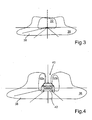
- Fig. 3
- eine schematische Darstellung, in welcher eine Grundlichtverteilung und ein der Grundlichtverteilung überlagerter Lichtkegel gezeigt sind;
- Fig. 4
- eine schematische Darstellung einer weiteren Grundlichtverteilung, wobei zwei Lichtkegel schematisch dargestellt sind, mittels welchen eine Beleuchtungsstärke angrenzend zu einem von der Grundlichtverteilung ausgesparten Fahrzeug dargestellt ist; und in
- Fig. 5
- eine weitere schematische Darstellung einer Grundlichtverteilung, wobei eine adaptive Ausleuchtung eines Fahrbahnverlaufs mittels eines Lichtkegels erfolgt.
- In den Figuren werden gleiche oder funktionsgleiche Elemente mit gleichen Bezugszeichen versehen.
- Ein Kraftfahrzeug 10 mit einer Beleuchtungsvorrichtung 12 ist in einer schematischen Draufsicht in
Fig. 1 gezeigt. Die Beleuchtungsvorrichtung 12 umfasst ein linkes Scheinwerfermodul 14 und ein rechtes Scheinwerfermodul 16. Die Scheinwerfermodule 14, 16 umfassen jeweils eine adaptive Beleuchtungseinheit 18, 20. Des Weiteren umfassen die Scheinwerfermodule 14, 16 jeweils weitere Beleuchtungseinheiten 22, welche dazu ausgebildet sind, eine Grundlichtverteilung mit einer Abblendlichtfunktion und einer Fernlichtfunktion bereitzustellen. - In
Fig. 2 ist einer der beiden adaptiven Beleuchtungseinheiten 18 in einer schematischen Perspektivansicht gezeigt. Die hier nicht dargestellte Beleuchtungseinheit 20, welche im rechten Scheinwerfermodul 16 angeordnet ist, ist im Wesentlichen genauso aufgebaut wie die hier schematisch gezeigte adaptive Beleuchtungseinheit 18. - Die adaptive Beleuchtungseinheit 18 umfasst eine unbeweglich angeordnete Beleuchtungsquelle 24, welche vorliegend als Laser ausgebildet ist. Des Weiteren weist die Beleuchtungseinheit 18 ein in einem Strahlengang 26 der Beleuchtungsquelle 24 angeordnetes optisches Bauelement 28 sowie eine Verstelleinrichtung 30 auf, welche dazu ausgebildet ist, das optische Bauelement 28 zu bewegen.
- Die Verstelleinrichtung 30 weist im vorliegenden Fall einen piezoelektrischen Aktor auf, wobei das optische Bauelement 28 derart angeordnet und ausgebildet ist, dass aus einer Bewegung des optischen Bauelements 28 mittels des piezoelektrischen Aktors 30 eine Verschwenkung eines mittels der Beleuchtungsquelle 24 im Zusammenwirken mit dem optischen Bauelement 28 erzeugbaren Lichtkegels 32 resultiert.
- Statt des piezoelektrischen Aktors kann die Verstelleinrichtung 30 beispielsweise einen elektrostatischen Aktor, eine Formgedächtnislegierung oder auch einen elektro-thermo-mechanischen Wandler umfassen, mittels welchen das optische Bauelement 28 bewegbar ist. Im Wesentlichen können sämtliche Aktoren als ein mikromechanischer Aktor eingesetzt werden, die in der Mikrosystemtechnik Anwendung finden.
- Im vorliegenden Fall handelt es sich bei dem optischen Bauelement 28 um eine Linse, mittels welcher der Strahlengang 26 der Beleuchtungsquelle 24 je nach Ausrichtung und/oder Positionierung des optischen Bauelements 28 gegenüber der Beleuchtungsquelle 24 unterschiedlich gebrochen bzw. gebeugt wird.
- Das optische Bauelement 28 ist in der vorliegend gezeigten Ausführungsform um eine Achse 34 verschwenkbar bzw. verdrehbar gelagert, wobei der piezoelektrische Aktor der Verstelleinrichtung 30 dazu ausgebildet ist, das optische Bauelement 28 um die Achse 34 zu verschwenken bzw. zu verdrehen. Der piezoelektrische Aktor kann beispielsweise in Form eines Mikrobiegeelements ausgebildet sein, wobei ein Piezomaterial beispielsweise auf ein piezoelektrisch inaktives Material aufgebracht ist. Sowohl das Piezomaterial als auch das piezoelektrisch inaktive Material sind in Form einer Balkeneinspannung eingespannt. Wird eine elektrische Spannung auf das Piezomaterial aufgebracht bzw. an dieses angelegt, wird eine durch einen Quereffekt verursachte Längenänderung des Piezomaterials durch das starre inaktive Material in eine Verkrümmung der gesamten Anordnung umgewandelt. Dadurch kann eine einfache Verschwenkung des optischen Bauelements 28 um die Achse 34 erfolgen. Im Wesentlichen können aber sämtliche mikromechanischen Aktoren, die Anwendung in der Mikrosystemtechnik finden, für die Verstelleinrichtung 30 zum Verschwenken des optischen Bauelements 28 eingesetzt werden.
- In dem vorliegend gezeigten Ausführungsbeispiel ist die Beleuchtungseinheit 18 derart angeordnet, dass der Lichtkegel 32 um die Fahrzeughochachse z verschwenkt werden kann. Mit anderen Worten kann der Lichtkegel 32 aus Sicht eines Fahrzeuginsassen nach links und rechts verschwenkt werden. Alternativ ist es auch möglich, dass das optische Bauelement 28 derart angeordnet und ausgebildet ist, dass der Lichtkegel 32 bei bestimmungsgemäßer Anordnung der adaptiven Beleuchtungseinheit 18 bzw. der gesamten Beleuchtungsvorrichtung 12 im Kraftfahrzeug 10 um die Fahrzeugquerachse y verschwenkbar ist. Mit anderen Worten kann der Leuchtkegel 32 also aus Sicht eines Fahrzeuginsassen nach oben und nach unten verschwenkt werden.
- Abweichend von der in
Fig. 2 dargestellten Ausführungsform der Beleuchtungseinheit 18 kann diese auch derart ausgebildet sein, dass eine translatorische Bewegbarkeit des optischen Bauelements 28 relativ zu dem unbeweglichen, also starr angeordneten, optischen Bauelement 28 möglich ist. Dadurch kann statt einer Verschwenkung des Lichtkegels 32 auch eine Fokussierung oder Defokussierung der Beleuchtungsquelle 24 erzielt werden. Wie bereits in Zusammenhang mit derFig. 1 erwähnt, umfassen die Scheinwerfermodule 14, 16 noch weitere Beleuchtungseinheiten 22, welche dazu ausgebildet sind, eine Grundlichtverteilung mit einer Abblendlichtfunktion und einer Fernlichtfunktion bereitzustellen. Mittels der Beleuchtungsquellen 24 der adaptiven Beleuchtungseinheiten 18, 20 im Zusammenwirken mit den jeweiligen optischen Bauelementen 28 erzeugbare Lichtkegel 32 sind dabei der Grundlichtverteilung überlagerbar. - Die weiteren Beleuchtungseinheiten 22 können zum Beispiel als Xenonscheinwerfer, LED-Scheinwerfer, auf Laserlicht basierende Scheinwerfer oder auch als Halogenscheinwerfer realisiert sein, mittels welchen die Abblendlichtfunktion und Fernlichtfunktion bereitgestellt werden kann.
- In
Fig. 3 ist eine erste mögliche Ausführungsform einer von dem Lichtkegel 32 überlagerten Grundlichtverteilung 36 schematisch dargestellt. Wie bereits erläutert, wird mittels der Beleuchtungseinheiten 22 die Grundlichtverteilung 36, welche ein Abblendlicht und/oder ein Fernlicht aufweist, erzeugt bzw. bereitgestellt. Der mittels der beiden adaptiven Beleuchtungseinheiten 18, 22 erzeugte Lichtkegel 32 wird dabei der Grundlichtverteilung 36 überlagert, was zur Erhöhung der Beleuchtungsstärke in einem Zentralbereich der Grundlichtverteilung 36 beiträgt. Dadurch kann beispielsweise eine Fahrbahn 38 in einem Fernbereich verstärkt ausgeleuchtet werden. - In
Fig. 4 ist eine weitere Einsatzmöglichkeit der adaptiven Beleuchtungseinheiten 18, 20 schematisch dargestellt. Wiederum wird mittels der Beleuchtungseinheiten 22 die Grundlichtverteilung 36 bereitgestellt bzw. erzeugt. Im vorliegenden Fall weist die Grundlichtverteilung 36 eine Aussparung 40 genau dort auf, wo sich ein vorausfahrendes Fahrzeug 42 befindet. Die beiden adaptiven Beleuchtungseinheiten 18, 20 werden dabei derart angesteuert, dass sich die beiden Lichtkegel 32a und 32b ergeben. Die Lichtkegel 32a, 32b werden somit als eine Art Teilfernlicht mit einer vertikalen Hell-Dunkel-Grenze eingesetzt. Dies dient insbesondere zur Erhöhung der Beleuchtungsstärke angrenzend an das durch die Grundlichtverteilung 36 ausgesparten vorausfahrenden Fahrzeugs 42. - In
Fig. 5 ist ein weiterer Anwendungsfall für die adaptiven Beleuchtungseinheiten 18, 20 schematisch dargestellt. Wiederum wird mittels der Beleuchtungseinheiten 22 die Grundlichtverteilung 36 bereitgestellt. Die beweglichen Lichtkegel 32 der Beleuchtungseinheiten 18, 22 dienen hierbei zur adaptiven Ausleuchtung der Fahrbahn 38 in Kurven als Topologieausgleich. Die beiden adaptiven Beleuchtungseinheiten 18, 22 werden im vorliegenden Fall als eine Art Teilfernlicht eingesetzt, mittels welchen insbesondere Kurvenverläufe besonders gut ausgeleuchtet werden können.
Claims (11)
- Beleuchtungsvorrichtung (12) für ein Kraftfahrzeug (10), mit zumindest einer adaptiven Beleuchtungseinheit (18, 20), welche eine unbeweglich angeordnete Beleuchtungsquelle (24) und wenigstens ein zumindest teilweise in einem Strahlengang (26) der Beleuchtungsquelle (24) angeordnetes, als Linse ausgebildetes optisches Bauelement (28) sowie eine Verstelleinrichtung (30) umfasst, welche dazu ausgebildet ist, das optische Bauelement (28) zu bewegen, wobei
die Verstelleinrichtung (30) einen mikromechanischen Aktor umfasst, wobei das optische Bauelement (28) derart angeordnet und ausgebildet ist, dass aus einer Bewegung des optischen Bauelements (28) mittels des mikromechanischen Aktors eine Verschwenkung eines mittels der Beleuchtungsquelle (24) im Zusammenwirken mit dem optischen Bauelement (28) erzeugbaren Lichtkegels (32, 32a, 32b) resultiert, wobei das optische Bauelement (28) um eine Achse (34) verschwenkbar gelagert und der mikromechanische Aktor dazu ausgebildet ist, das optische Bauelement (28) um die Achse (34) zu verschwenken. - Beleuchtungsvorrichtung (12) nach Anspruch 1,
dadurch gekennzeichnet, dass
der mikromechanische Aktor ein piezoelektrischer Aktor ist. - Beleuchtungsvorrichtung (12) nach Anspruch 1 oder 2,
dadurch gekennzeichnet, dass
die Beleuchtungsquelle (24) ein Laser, eine LED oder eine Hochleistungs-LED ist. - Beleuchtungsvorrichtung (12) nach einem der vorhergehenden Ansprüche,
dadurch gekennzeichnet, dass
die Beleuchtungsvorrichtung (12) dazu ausgebildet ist, eine Grundlichtverteilung (36) mit einer Abblendlichtfunktion und/oder einer Fernlichtfunktion, einer Teilfernlichtfunktion oder Markierungslichtfunktion bereitzustellen, wobei der mittels der Beleuchtungsquelle (24) im Zusammenwirken mit dem optischen Bauelement (28) erzeugbare Lichtkegel (32, 32a, 32b) der Grundlichtverteilung (36) zumindest teilweise überlagerbar ist. - Kraftfahrzeug (10) mit einer Beleuchtungsvorrichtung (12) nach einem der vorhergehenden Ansprüche.
- Kraftfahrzeug (10) nach Anspruch 5,
dadurch gekennzeichnet, dass
die Beleuchtungsvorrichtung (12) zwei der adaptiven Beleuchtungseinheiten (18, 20) aufweist, wobei eine der adaptiven Beleuchtungseinheiten (18) in einem linken Scheinwerfermodul (14) des Kraftfahrzeugs (10) und eine der adaptiven Beleuchtungseinheiten (20) in einem rechten Scheinwerfermodul (16) des Kraftfahrzeugs (10) angeordnet ist. - Verfahren zum Betreiben einer Beleuchtungsvorrichtung (12) eines Kraftfahrzeugs (10), bei welchem ein zumindest teilweise in einem Strahlengang (26) einer Beleuchtungsquelle (24) von zumindest einer adaptiven Beleuchtungseinheit (18, 20) angeordnetes, als Linse ausgebildetes optisches Bauelement (28) mittels einer Verstelleinrichtung (30) bewegt wird, wobei
die Verstelleinrichtung (30) einen mikromechanischen Aktor umfasst, mittels welchem das optische Bauelement (28) derart bewegt wird, dass ein mittels der Beleuchtungsquelle (24) im Zusammenwirken mit dem optischen Bauelement (28) erzeugter Lichtkegel (32, 32a, 32b) verschwenkt wird, wobei das optische Bauelement (28) um eine Achse (34) verschwenkbar gelagert ist und das optische Bauelement (28) mittels des mikromechanischen Aktors um die Achse (34) verschwenkt wird. - Verfahren nach Anspruch 7,
dadurch gekennzeichnet, dass
der mikromechanische Aktor zum Bewegen des optischen Bauelements (28) in Abhängigkeit von einer erfassten Verkehrssituation des Kraftfahrzeugs (10) angesteuert wird. - Verfahren nach Anspruch 7 oder 8,
dadurch gekennzeichnet, dass
der Lichtkegel (32) derart verschwenkt wird, dass eine von der Beleuchtungsvorrichtung (12) bereitgestellte Grundlichtverteilung (36) zur Erhöhung der Lichtstärke von dem Lichtkegel (32) überlagert wird. - Verfahren nach einem der Ansprüche 7 bis 9,
dadurch gekennzeichnet, dass
der Lichtkegel (32a, 32b) derart verschwenkt wird, dass ein Objekt, insbesondere ein anderer Verkehrsteilnehmer (42), ausgeblendet wird. - Verfahren nach einem der Ansprüche 7 bis 10,
dadurch gekennzeichnet, dass
der Lichtkegel (32) derart verschwenkt wird, dass eine Fahrbahn (38) adaptiv ausgeleuchtet wird.
Applications Claiming Priority (1)
| Application Number | Priority Date | Filing Date | Title |
|---|---|---|---|
| DE102014017978.8A DE102014017978A1 (de) | 2014-12-04 | 2014-12-04 | Beleuchtungsvorrichtung für ein Kraftfahrzeug, Kraftfahrzeug mit einer Beleuchtungsvorrichtung und Verfahren zum Betreiben einer Beleuchtungsvorrichtung |
Publications (2)
| Publication Number | Publication Date |
|---|---|
| EP3028896A1 true EP3028896A1 (de) | 2016-06-08 |
| EP3028896B1 EP3028896B1 (de) | 2020-09-16 |
Family
ID=54705346
Family Applications (1)
| Application Number | Title | Priority Date | Filing Date |
|---|---|---|---|
| EP15003338.9A Active EP3028896B1 (de) | 2014-12-04 | 2015-11-21 | Beleuchtungsvorrichtung für ein kraftfahrzeug, kraftfahrzeug mit einer beleuchtungsvorrichtung und verfahren zum betreiben einer beleuchtungsvorrichtung |
Country Status (2)
| Country | Link |
|---|---|
| EP (1) | EP3028896B1 (de) |
| DE (1) | DE102014017978A1 (de) |
Families Citing this family (1)
| Publication number | Priority date | Publication date | Assignee | Title |
|---|---|---|---|---|
| DE102017214407A1 (de) * | 2017-08-18 | 2019-02-21 | Osram Gmbh | Beleuchtungssystem und scheinwerfer |
Citations (21)
| Publication number | Priority date | Publication date | Assignee | Title |
|---|---|---|---|---|
| DE19625923A1 (de) | 1996-06-28 | 1998-01-08 | Hella Kg Hueck & Co | Scheinwerfer für Fahrzeuge |
| DE19737653A1 (de) | 1997-08-29 | 1999-03-04 | Patent Treuhand Ges Fuer Elektrische Gluehlampen Mbh | Beleuchtungseinrichtung für Fahrzeuge und Betriebsverfahren für eine derartige Beleuchtungseinrichtung |
| DE10005795A1 (de) | 2000-02-10 | 2001-08-23 | Inst Mikrotechnik Mainz Gmbh | Steuerbarer Scheinwerfer |
| DE10321564A1 (de) | 2003-05-14 | 2004-12-16 | Audi Ag | Kraftfahrzeugscheinwerfer |
| JP2006179246A (ja) * | 2004-12-21 | 2006-07-06 | Ichikoh Ind Ltd | 車両用前照灯ユニット |
| JP2008010265A (ja) * | 2006-06-28 | 2008-01-17 | Ichikoh Ind Ltd | 車両用前照灯 |
| DE102007049361A1 (de) | 2006-10-23 | 2008-05-08 | Zizala Lichtsysteme Gmbh | Optikelement für einen Fahrzeugscheinwerfer |
| DE202007018181U1 (de) | 2007-12-31 | 2008-05-08 | Automotive Lighting Reutlingen Gmbh | Projektionsmodul mit dynamischer Kurvenlichtfunktion |
| JP2009206015A (ja) * | 2008-02-29 | 2009-09-10 | Nissan Motor Co Ltd | 車両用前照灯装置 |
| DE102008022795A1 (de) | 2008-05-08 | 2009-11-12 | Osram Opto Semiconductors Gmbh | Kfz-Scheinwerfer |
| EP2128521A1 (de) | 2008-05-27 | 2009-12-02 | Valeo Vision | Kraftfahrzeugscheinwerfer, der in der Lage ist, einen schwenkbaren Lichtstrahl abzugeben |
| US20100061090A1 (en) | 2005-07-13 | 2010-03-11 | Koninklijke Philips Electronics, N.V. | Illumination system |
| DE102009035743A1 (de) | 2009-08-01 | 2011-02-17 | Automotive Lighting Reutlingen Gmbh | Lichtmodul für einen Kraftfahrzeugscheinwerfer |
| US20120026746A1 (en) * | 2009-01-05 | 2012-02-02 | Koninklijke Philips Electronics N.V. | Lighting assembly and automotive headlamp arrangement |
| EP2434204A2 (de) * | 2010-09-27 | 2012-03-28 | Audi AG | Scheinwerfer für ein Kraftfahrzeug und Kraftfahrzeug |
| WO2012098142A1 (fr) * | 2011-01-20 | 2012-07-26 | Valeo Vision | Module de projection d'un faisceau |
| DE102012205435A1 (de) * | 2012-04-03 | 2013-10-10 | Bayerische Motoren Werke Aktiengesellschaft | Beleuchtungsvorrichtung für ein Kraftfahrzeug |
| DE102013003959A1 (de) | 2012-06-26 | 2014-01-02 | Volkswagen Ag | Verfahren zum Betreiben eines Scheinwerfersystems in einem Fahrzeug und dazugehöriges Scheinwerfersystem |
| GB2504330A (en) * | 2012-07-26 | 2014-01-29 | Sharp Kk | Headlight system incorporating adaptive beam function |
| EP2719942A1 (de) * | 2011-06-08 | 2014-04-16 | Koito Manufacturing Co., Ltd. | Optische einheit |
| DE102012224345A1 (de) | 2012-12-21 | 2014-06-26 | Osram Gmbh | Fahrzeug-Leuchtvorrichtung |
-
2014
- 2014-12-04 DE DE102014017978.8A patent/DE102014017978A1/de not_active Ceased
-
2015
- 2015-11-21 EP EP15003338.9A patent/EP3028896B1/de active Active
Patent Citations (21)
| Publication number | Priority date | Publication date | Assignee | Title |
|---|---|---|---|---|
| DE19625923A1 (de) | 1996-06-28 | 1998-01-08 | Hella Kg Hueck & Co | Scheinwerfer für Fahrzeuge |
| DE19737653A1 (de) | 1997-08-29 | 1999-03-04 | Patent Treuhand Ges Fuer Elektrische Gluehlampen Mbh | Beleuchtungseinrichtung für Fahrzeuge und Betriebsverfahren für eine derartige Beleuchtungseinrichtung |
| DE10005795A1 (de) | 2000-02-10 | 2001-08-23 | Inst Mikrotechnik Mainz Gmbh | Steuerbarer Scheinwerfer |
| DE10321564A1 (de) | 2003-05-14 | 2004-12-16 | Audi Ag | Kraftfahrzeugscheinwerfer |
| JP2006179246A (ja) * | 2004-12-21 | 2006-07-06 | Ichikoh Ind Ltd | 車両用前照灯ユニット |
| US20100061090A1 (en) | 2005-07-13 | 2010-03-11 | Koninklijke Philips Electronics, N.V. | Illumination system |
| JP2008010265A (ja) * | 2006-06-28 | 2008-01-17 | Ichikoh Ind Ltd | 車両用前照灯 |
| DE102007049361A1 (de) | 2006-10-23 | 2008-05-08 | Zizala Lichtsysteme Gmbh | Optikelement für einen Fahrzeugscheinwerfer |
| DE202007018181U1 (de) | 2007-12-31 | 2008-05-08 | Automotive Lighting Reutlingen Gmbh | Projektionsmodul mit dynamischer Kurvenlichtfunktion |
| JP2009206015A (ja) * | 2008-02-29 | 2009-09-10 | Nissan Motor Co Ltd | 車両用前照灯装置 |
| DE102008022795A1 (de) | 2008-05-08 | 2009-11-12 | Osram Opto Semiconductors Gmbh | Kfz-Scheinwerfer |
| EP2128521A1 (de) | 2008-05-27 | 2009-12-02 | Valeo Vision | Kraftfahrzeugscheinwerfer, der in der Lage ist, einen schwenkbaren Lichtstrahl abzugeben |
| US20120026746A1 (en) * | 2009-01-05 | 2012-02-02 | Koninklijke Philips Electronics N.V. | Lighting assembly and automotive headlamp arrangement |
| DE102009035743A1 (de) | 2009-08-01 | 2011-02-17 | Automotive Lighting Reutlingen Gmbh | Lichtmodul für einen Kraftfahrzeugscheinwerfer |
| EP2434204A2 (de) * | 2010-09-27 | 2012-03-28 | Audi AG | Scheinwerfer für ein Kraftfahrzeug und Kraftfahrzeug |
| WO2012098142A1 (fr) * | 2011-01-20 | 2012-07-26 | Valeo Vision | Module de projection d'un faisceau |
| EP2719942A1 (de) * | 2011-06-08 | 2014-04-16 | Koito Manufacturing Co., Ltd. | Optische einheit |
| DE102012205435A1 (de) * | 2012-04-03 | 2013-10-10 | Bayerische Motoren Werke Aktiengesellschaft | Beleuchtungsvorrichtung für ein Kraftfahrzeug |
| DE102013003959A1 (de) | 2012-06-26 | 2014-01-02 | Volkswagen Ag | Verfahren zum Betreiben eines Scheinwerfersystems in einem Fahrzeug und dazugehöriges Scheinwerfersystem |
| GB2504330A (en) * | 2012-07-26 | 2014-01-29 | Sharp Kk | Headlight system incorporating adaptive beam function |
| DE102012224345A1 (de) | 2012-12-21 | 2014-06-26 | Osram Gmbh | Fahrzeug-Leuchtvorrichtung |
Also Published As
| Publication number | Publication date |
|---|---|
| DE102014017978A1 (de) | 2016-06-09 |
| EP3028896B1 (de) | 2020-09-16 |
Similar Documents
| Publication | Publication Date | Title |
|---|---|---|
| DE102018008760B4 (de) | Fahrzeugscheinwerfer mit einer Lichtquelle | |
| DE102017129254B4 (de) | Fahrzeugscheinwerfer | |
| DE102009057219B4 (de) | Vorrichtung zur Steuerung eines Fahrlichts eines Fahrzeugs | |
| EP3033248B1 (de) | Verfahren zum steuern einer scheinwerferanordnung für ein fahrzeug und scheinwerferanordnung | |
| EP3092438B1 (de) | Leuchtvorrichtung mit mikrospiegeln für ein kraftfahrzeug und verfahren zur steuerung der leuchtvorrichtung | |
| WO2009112125A1 (de) | Verfahren zur fahrlichtsteuerung eines fahrzeugs | |
| EP0937942A2 (de) | Scheinwerfer für Fahrzeuge nach dem Projektionsprinzip | |
| DE202010018458U1 (de) | Optische Vorrichtung für Kraftfahrzeug | |
| DE102010048659A1 (de) | Beleuchtungseinrichtung eines Kraftfahrzeugs | |
| EP1826476B1 (de) | Beleuchtungsvorrichtung für ein Fahrzeug | |
| DE102009033910A1 (de) | Beleuchtungseinrichtung für ein Kraftfahrzeug | |
| DE19961942A1 (de) | Scheinwerferanlage für Fahrzeuge zur Erzeugung von Lichtbündeln mit unterschiedlicher Charakteristik | |
| EP3548336B1 (de) | Ändern eines helligkeitsgradienten eines scheinwerfers durch dimmen von leuchtpunkten | |
| DE102007048717A1 (de) | Vorrichtung und Verfahren zum Reduzieren der Lichtblendung eines Fahrers eines Kraftfahrzeugs | |
| DE102011012742B4 (de) | Projektionsmodul für einen Fahrzeugscheinwerfer und Fahrzeugscheinwerfer | |
| DE102015203887A1 (de) | Beleuchtungsvorrichtung | |
| WO2016070962A1 (de) | Scheinwerfer für ein kraftfahrzeug und verfahren zum betreiben eines scheinwerfers | |
| DE102010062278B4 (de) | Kraftfahrzeugscheinwerfer mit einem Projektionslichtmodul und einem Mehrpunkt-Blendenstellmechanismus | |
| WO2023285343A1 (de) | Scheinwerfer für ein fahrzeug | |
| DE102019118981B4 (de) | Optische Vorrichtung, Scheinwerfer, Fahrzeug und Verfahren | |
| DE102007022245A1 (de) | Scheinwerfer für Fahrzeuge | |
| EP3028896B1 (de) | Beleuchtungsvorrichtung für ein kraftfahrzeug, kraftfahrzeug mit einer beleuchtungsvorrichtung und verfahren zum betreiben einer beleuchtungsvorrichtung | |
| EP0923695B2 (de) | Scheinwerferanlage für fahrzeuge für abblendlicht und fernlicht | |
| DE102004063836A1 (de) | Scheinwerfersteuerung | |
| EP2977263B1 (de) | Verfahren zum betreiben eines kraftwagens mit einem scheinwerfer, kraftwagen sowie scheinwerfer |
Legal Events
| Date | Code | Title | Description |
|---|---|---|---|
| PUAI | Public reference made under article 153(3) epc to a published international application that has entered the european phase |
Free format text: ORIGINAL CODE: 0009012 |
|
| AK | Designated contracting states |
Kind code of ref document: A1 Designated state(s): AL AT BE BG CH CY CZ DE DK EE ES FI FR GB GR HR HU IE IS IT LI LT LU LV MC MK MT NL NO PL PT RO RS SE SI SK SM TR |
|
| AX | Request for extension of the european patent |
Extension state: BA ME |
|
| STAA | Information on the status of an ep patent application or granted ep patent |
Free format text: STATUS: REQUEST FOR EXAMINATION WAS MADE |
|
| 17P | Request for examination filed |
Effective date: 20161208 |
|
| RBV | Designated contracting states (corrected) |
Designated state(s): AL AT BE BG CH CY CZ DE DK EE ES FI FR GB GR HR HU IE IS IT LI LT LU LV MC MK MT NL NO PL PT RO RS SE SI SK SM TR |
|
| STAA | Information on the status of an ep patent application or granted ep patent |
Free format text: STATUS: EXAMINATION IS IN PROGRESS |
|
| 17Q | First examination report despatched |
Effective date: 20200123 |
|
| GRAP | Despatch of communication of intention to grant a patent |
Free format text: ORIGINAL CODE: EPIDOSNIGR1 |
|
| STAA | Information on the status of an ep patent application or granted ep patent |
Free format text: STATUS: GRANT OF PATENT IS INTENDED |
|
| RIC1 | Information provided on ipc code assigned before grant |
Ipc: F21S 41/16 20180101ALI20200603BHEP Ipc: F21S 41/63 20180101ALI20200603BHEP Ipc: F21S 41/143 20180101ALI20200603BHEP Ipc: B60Q 1/12 20060101ALI20200603BHEP Ipc: B60Q 1/08 20060101AFI20200603BHEP Ipc: F21S 41/151 20180101ALI20200603BHEP |
|
| INTG | Intention to grant announced |
Effective date: 20200624 |
|
| GRAS | Grant fee paid |
Free format text: ORIGINAL CODE: EPIDOSNIGR3 |
|
| GRAA | (expected) grant |
Free format text: ORIGINAL CODE: 0009210 |
|
| STAA | Information on the status of an ep patent application or granted ep patent |
Free format text: STATUS: THE PATENT HAS BEEN GRANTED |
|
| AK | Designated contracting states |
Kind code of ref document: B1 Designated state(s): AL AT BE BG CH CY CZ DE DK EE ES FI FR GB GR HR HU IE IS IT LI LT LU LV MC MK MT NL NO PL PT RO RS SE SI SK SM TR |
|
| REG | Reference to a national code |
Ref country code: GB Ref legal event code: FG4D Free format text: NOT ENGLISH |
|
| REG | Reference to a national code |
Ref country code: CH Ref legal event code: EP |
|
| REG | Reference to a national code |
Ref country code: DE Ref legal event code: R096 Ref document number: 502015013451 Country of ref document: DE |
|
| REG | Reference to a national code |
Ref country code: IE Ref legal event code: FG4D Free format text: LANGUAGE OF EP DOCUMENT: GERMAN |
|
| REG | Reference to a national code |
Ref country code: AT Ref legal event code: REF Ref document number: 1313882 Country of ref document: AT Kind code of ref document: T Effective date: 20201015 |
|
| PG25 | Lapsed in a contracting state [announced via postgrant information from national office to epo] |
Ref country code: NO Free format text: LAPSE BECAUSE OF FAILURE TO SUBMIT A TRANSLATION OF THE DESCRIPTION OR TO PAY THE FEE WITHIN THE PRESCRIBED TIME-LIMIT Effective date: 20201216 Ref country code: SE Free format text: LAPSE BECAUSE OF FAILURE TO SUBMIT A TRANSLATION OF THE DESCRIPTION OR TO PAY THE FEE WITHIN THE PRESCRIBED TIME-LIMIT Effective date: 20200916 Ref country code: GR Free format text: LAPSE BECAUSE OF FAILURE TO SUBMIT A TRANSLATION OF THE DESCRIPTION OR TO PAY THE FEE WITHIN THE PRESCRIBED TIME-LIMIT Effective date: 20201217 Ref country code: BG Free format text: LAPSE BECAUSE OF FAILURE TO SUBMIT A TRANSLATION OF THE DESCRIPTION OR TO PAY THE FEE WITHIN THE PRESCRIBED TIME-LIMIT Effective date: 20201216 Ref country code: FI Free format text: LAPSE BECAUSE OF FAILURE TO SUBMIT A TRANSLATION OF THE DESCRIPTION OR TO PAY THE FEE WITHIN THE PRESCRIBED TIME-LIMIT Effective date: 20200916 Ref country code: HR Free format text: LAPSE BECAUSE OF FAILURE TO SUBMIT A TRANSLATION OF THE DESCRIPTION OR TO PAY THE FEE WITHIN THE PRESCRIBED TIME-LIMIT Effective date: 20200916 |
|
| REG | Reference to a national code |
Ref country code: NL Ref legal event code: MP Effective date: 20200916 |
|
| PG25 | Lapsed in a contracting state [announced via postgrant information from national office to epo] |
Ref country code: LV Free format text: LAPSE BECAUSE OF FAILURE TO SUBMIT A TRANSLATION OF THE DESCRIPTION OR TO PAY THE FEE WITHIN THE PRESCRIBED TIME-LIMIT Effective date: 20200916 Ref country code: RS Free format text: LAPSE BECAUSE OF FAILURE TO SUBMIT A TRANSLATION OF THE DESCRIPTION OR TO PAY THE FEE WITHIN THE PRESCRIBED TIME-LIMIT Effective date: 20200916 |
|
| REG | Reference to a national code |
Ref country code: LT Ref legal event code: MG4D |
|
| PG25 | Lapsed in a contracting state [announced via postgrant information from national office to epo] |
Ref country code: EE Free format text: LAPSE BECAUSE OF FAILURE TO SUBMIT A TRANSLATION OF THE DESCRIPTION OR TO PAY THE FEE WITHIN THE PRESCRIBED TIME-LIMIT Effective date: 20200916 Ref country code: SM Free format text: LAPSE BECAUSE OF FAILURE TO SUBMIT A TRANSLATION OF THE DESCRIPTION OR TO PAY THE FEE WITHIN THE PRESCRIBED TIME-LIMIT Effective date: 20200916 Ref country code: RO Free format text: LAPSE BECAUSE OF FAILURE TO SUBMIT A TRANSLATION OF THE DESCRIPTION OR TO PAY THE FEE WITHIN THE PRESCRIBED TIME-LIMIT Effective date: 20200916 Ref country code: NL Free format text: LAPSE BECAUSE OF FAILURE TO SUBMIT A TRANSLATION OF THE DESCRIPTION OR TO PAY THE FEE WITHIN THE PRESCRIBED TIME-LIMIT Effective date: 20200916 Ref country code: LT Free format text: LAPSE BECAUSE OF FAILURE TO SUBMIT A TRANSLATION OF THE DESCRIPTION OR TO PAY THE FEE WITHIN THE PRESCRIBED TIME-LIMIT Effective date: 20200916 Ref country code: PT Free format text: LAPSE BECAUSE OF FAILURE TO SUBMIT A TRANSLATION OF THE DESCRIPTION OR TO PAY THE FEE WITHIN THE PRESCRIBED TIME-LIMIT Effective date: 20210118 Ref country code: CZ Free format text: LAPSE BECAUSE OF FAILURE TO SUBMIT A TRANSLATION OF THE DESCRIPTION OR TO PAY THE FEE WITHIN THE PRESCRIBED TIME-LIMIT Effective date: 20200916 |
|
| PG25 | Lapsed in a contracting state [announced via postgrant information from national office to epo] |
Ref country code: ES Free format text: LAPSE BECAUSE OF FAILURE TO SUBMIT A TRANSLATION OF THE DESCRIPTION OR TO PAY THE FEE WITHIN THE PRESCRIBED TIME-LIMIT Effective date: 20200916 Ref country code: AL Free format text: LAPSE BECAUSE OF FAILURE TO SUBMIT A TRANSLATION OF THE DESCRIPTION OR TO PAY THE FEE WITHIN THE PRESCRIBED TIME-LIMIT Effective date: 20200916 Ref country code: IS Free format text: LAPSE BECAUSE OF FAILURE TO SUBMIT A TRANSLATION OF THE DESCRIPTION OR TO PAY THE FEE WITHIN THE PRESCRIBED TIME-LIMIT Effective date: 20210116 Ref country code: PL Free format text: LAPSE BECAUSE OF FAILURE TO SUBMIT A TRANSLATION OF THE DESCRIPTION OR TO PAY THE FEE WITHIN THE PRESCRIBED TIME-LIMIT Effective date: 20200916 |
|
| REG | Reference to a national code |
Ref country code: DE Ref legal event code: R097 Ref document number: 502015013451 Country of ref document: DE |
|
| PG25 | Lapsed in a contracting state [announced via postgrant information from national office to epo] |
Ref country code: SK Free format text: LAPSE BECAUSE OF FAILURE TO SUBMIT A TRANSLATION OF THE DESCRIPTION OR TO PAY THE FEE WITHIN THE PRESCRIBED TIME-LIMIT Effective date: 20200916 Ref country code: MC Free format text: LAPSE BECAUSE OF FAILURE TO SUBMIT A TRANSLATION OF THE DESCRIPTION OR TO PAY THE FEE WITHIN THE PRESCRIBED TIME-LIMIT Effective date: 20200916 |
|
| REG | Reference to a national code |
Ref country code: CH Ref legal event code: PL |
|
| PLBE | No opposition filed within time limit |
Free format text: ORIGINAL CODE: 0009261 |
|
| STAA | Information on the status of an ep patent application or granted ep patent |
Free format text: STATUS: NO OPPOSITION FILED WITHIN TIME LIMIT |
|
| PG25 | Lapsed in a contracting state [announced via postgrant information from national office to epo] |
Ref country code: LU Free format text: LAPSE BECAUSE OF NON-PAYMENT OF DUE FEES Effective date: 20201121 |
|
| REG | Reference to a national code |
Ref country code: BE Ref legal event code: MM Effective date: 20201130 |
|
| 26N | No opposition filed |
Effective date: 20210617 |
|
| PG25 | Lapsed in a contracting state [announced via postgrant information from national office to epo] |
Ref country code: LI Free format text: LAPSE BECAUSE OF NON-PAYMENT OF DUE FEES Effective date: 20201130 Ref country code: SI Free format text: LAPSE BECAUSE OF FAILURE TO SUBMIT A TRANSLATION OF THE DESCRIPTION OR TO PAY THE FEE WITHIN THE PRESCRIBED TIME-LIMIT Effective date: 20200916 Ref country code: DK Free format text: LAPSE BECAUSE OF FAILURE TO SUBMIT A TRANSLATION OF THE DESCRIPTION OR TO PAY THE FEE WITHIN THE PRESCRIBED TIME-LIMIT Effective date: 20200916 Ref country code: CH Free format text: LAPSE BECAUSE OF NON-PAYMENT OF DUE FEES Effective date: 20201130 |
|
| PG25 | Lapsed in a contracting state [announced via postgrant information from national office to epo] |
Ref country code: IE Free format text: LAPSE BECAUSE OF NON-PAYMENT OF DUE FEES Effective date: 20201121 Ref country code: IT Free format text: LAPSE BECAUSE OF FAILURE TO SUBMIT A TRANSLATION OF THE DESCRIPTION OR TO PAY THE FEE WITHIN THE PRESCRIBED TIME-LIMIT Effective date: 20200916 |
|
| REG | Reference to a national code |
Ref country code: AT Ref legal event code: MM01 Ref document number: 1313882 Country of ref document: AT Kind code of ref document: T Effective date: 20201121 |
|
| PG25 | Lapsed in a contracting state [announced via postgrant information from national office to epo] |
Ref country code: AT Free format text: LAPSE BECAUSE OF NON-PAYMENT OF DUE FEES Effective date: 20201121 |
|
| PG25 | Lapsed in a contracting state [announced via postgrant information from national office to epo] |
Ref country code: TR Free format text: LAPSE BECAUSE OF FAILURE TO SUBMIT A TRANSLATION OF THE DESCRIPTION OR TO PAY THE FEE WITHIN THE PRESCRIBED TIME-LIMIT Effective date: 20200916 Ref country code: MT Free format text: LAPSE BECAUSE OF FAILURE TO SUBMIT A TRANSLATION OF THE DESCRIPTION OR TO PAY THE FEE WITHIN THE PRESCRIBED TIME-LIMIT Effective date: 20200916 Ref country code: CY Free format text: LAPSE BECAUSE OF FAILURE TO SUBMIT A TRANSLATION OF THE DESCRIPTION OR TO PAY THE FEE WITHIN THE PRESCRIBED TIME-LIMIT Effective date: 20200916 |
|
| PG25 | Lapsed in a contracting state [announced via postgrant information from national office to epo] |
Ref country code: MK Free format text: LAPSE BECAUSE OF FAILURE TO SUBMIT A TRANSLATION OF THE DESCRIPTION OR TO PAY THE FEE WITHIN THE PRESCRIBED TIME-LIMIT Effective date: 20200916 |
|
| PG25 | Lapsed in a contracting state [announced via postgrant information from national office to epo] |
Ref country code: BE Free format text: LAPSE BECAUSE OF NON-PAYMENT OF DUE FEES Effective date: 20201130 |
|
| P01 | Opt-out of the competence of the unified patent court (upc) registered |
Effective date: 20230530 |
|
| PGFP | Annual fee paid to national office [announced via postgrant information from national office to epo] |
Ref country code: GB Payment date: 20231123 Year of fee payment: 9 |
|
| PGFP | Annual fee paid to national office [announced via postgrant information from national office to epo] |
Ref country code: FR Payment date: 20231127 Year of fee payment: 9 Ref country code: DE Payment date: 20231130 Year of fee payment: 9 |
|
| REG | Reference to a national code |
Ref country code: DE Ref legal event code: R119 Ref document number: 502015013451 Country of ref document: DE |
|
| GBPC | Gb: european patent ceased through non-payment of renewal fee |
Effective date: 20241121 |
|
| PG25 | Lapsed in a contracting state [announced via postgrant information from national office to epo] |
Ref country code: DE Free format text: LAPSE BECAUSE OF NON-PAYMENT OF DUE FEES Effective date: 20250603 |
|
| PG25 | Lapsed in a contracting state [announced via postgrant information from national office to epo] |
Ref country code: GB Free format text: LAPSE BECAUSE OF NON-PAYMENT OF DUE FEES Effective date: 20241121 |
|
| PG25 | Lapsed in a contracting state [announced via postgrant information from national office to epo] |
Ref country code: FR Free format text: LAPSE BECAUSE OF NON-PAYMENT OF DUE FEES Effective date: 20241130 |