EP3028684B1 - Verschlussentlüftungsfilter und montageverfahren - Google Patents
Verschlussentlüftungsfilter und montageverfahren Download PDFInfo
- Publication number
- EP3028684B1 EP3028684B1 EP16150548.2A EP16150548A EP3028684B1 EP 3028684 B1 EP3028684 B1 EP 3028684B1 EP 16150548 A EP16150548 A EP 16150548A EP 3028684 B1 EP3028684 B1 EP 3028684B1
- Authority
- EP
- European Patent Office
- Prior art keywords
- layer
- filter assembly
- filter
- adhesive
- bag
- Prior art date
- Legal status (The legal status is an assumption and is not a legal conclusion. Google has not performed a legal analysis and makes no representation as to the accuracy of the status listed.)
- Active
Links
Images


Classifications
-
- A—HUMAN NECESSITIES
- A61—MEDICAL OR VETERINARY SCIENCE; HYGIENE
- A61F—FILTERS IMPLANTABLE INTO BLOOD VESSELS; PROSTHESES; DEVICES PROVIDING PATENCY TO, OR PREVENTING COLLAPSING OF, TUBULAR STRUCTURES OF THE BODY, e.g. STENTS; ORTHOPAEDIC, NURSING OR CONTRACEPTIVE DEVICES; FOMENTATION; TREATMENT OR PROTECTION OF EYES OR EARS; BANDAGES, DRESSINGS OR ABSORBENT PADS; FIRST-AID KITS
- A61F5/00—Orthopaedic methods or devices for non-surgical treatment of bones or joints; Nursing devices ; Anti-rape devices
- A61F5/44—Devices worn by the patient for reception of urine, faeces, catamenial or other discharge; Colostomy devices
- A61F5/441—Devices worn by the patient for reception of urine, faeces, catamenial or other discharge; Colostomy devices having venting or deodorant means, e.g. filters ; having antiseptic means, e.g. bacterial barriers
-
- A—HUMAN NECESSITIES
- A61—MEDICAL OR VETERINARY SCIENCE; HYGIENE
- A61F—FILTERS IMPLANTABLE INTO BLOOD VESSELS; PROSTHESES; DEVICES PROVIDING PATENCY TO, OR PREVENTING COLLAPSING OF, TUBULAR STRUCTURES OF THE BODY, e.g. STENTS; ORTHOPAEDIC, NURSING OR CONTRACEPTIVE DEVICES; FOMENTATION; TREATMENT OR PROTECTION OF EYES OR EARS; BANDAGES, DRESSINGS OR ABSORBENT PADS; FIRST-AID KITS
- A61F5/00—Orthopaedic methods or devices for non-surgical treatment of bones or joints; Nursing devices ; Anti-rape devices
- A61F5/44—Devices worn by the patient for reception of urine, faeces, catamenial or other discharge; Colostomy devices
- A61F5/4404—Details or parts
- A61F5/4405—Valves or valve arrangements specially adapted therefor ; Fluid inlets or outlets
-
- A—HUMAN NECESSITIES
- A61—MEDICAL OR VETERINARY SCIENCE; HYGIENE
- A61F—FILTERS IMPLANTABLE INTO BLOOD VESSELS; PROSTHESES; DEVICES PROVIDING PATENCY TO, OR PREVENTING COLLAPSING OF, TUBULAR STRUCTURES OF THE BODY, e.g. STENTS; ORTHOPAEDIC, NURSING OR CONTRACEPTIVE DEVICES; FOMENTATION; TREATMENT OR PROTECTION OF EYES OR EARS; BANDAGES, DRESSINGS OR ABSORBENT PADS; FIRST-AID KITS
- A61F5/00—Orthopaedic methods or devices for non-surgical treatment of bones or joints; Nursing devices ; Anti-rape devices
- A61F5/44—Devices worn by the patient for reception of urine, faeces, catamenial or other discharge; Colostomy devices
- A61F5/445—Colostomy, ileostomy or urethrostomy devices
-
- B—PERFORMING OPERATIONS; TRANSPORTING
- B01—PHYSICAL OR CHEMICAL PROCESSES OR APPARATUS IN GENERAL
- B01D—SEPARATION
- B01D39/00—Filtering material for liquid or gaseous fluids
- B01D39/14—Other self-supporting filtering material ; Other filtering material
- B01D39/16—Other self-supporting filtering material ; Other filtering material of organic material, e.g. synthetic fibres
- B01D39/1692—Other shaped material, e.g. perforated or porous sheets
-
- B—PERFORMING OPERATIONS; TRANSPORTING
- B01—PHYSICAL OR CHEMICAL PROCESSES OR APPARATUS IN GENERAL
- B01D—SEPARATION
- B01D46/00—Filters or filtering processes specially modified for separating dispersed particles from gases or vapours
- B01D46/0027—Filters or filtering processes specially modified for separating dispersed particles from gases or vapours with additional separating or treating functions
- B01D46/0036—Filters or filtering processes specially modified for separating dispersed particles from gases or vapours with additional separating or treating functions by adsorption or absorption
-
- B—PERFORMING OPERATIONS; TRANSPORTING
- B01—PHYSICAL OR CHEMICAL PROCESSES OR APPARATUS IN GENERAL
- B01D—SEPARATION
- B01D46/00—Filters or filtering processes specially modified for separating dispersed particles from gases or vapours
- B01D46/02—Particle separators, e.g. dust precipitators, having hollow filters made of flexible material
-
- B—PERFORMING OPERATIONS; TRANSPORTING
- B65—CONVEYING; PACKING; STORING; HANDLING THIN OR FILAMENTARY MATERIAL
- B65D—CONTAINERS FOR STORAGE OR TRANSPORT OF ARTICLES OR MATERIALS, e.g. BAGS, BARRELS, BOTTLES, BOXES, CANS, CARTONS, CRATES, DRUMS, JARS, TANKS, HOPPERS, FORWARDING CONTAINERS; ACCESSORIES, CLOSURES, OR FITTINGS THEREFOR; PACKAGING ELEMENTS; PACKAGES
- B65D33/00—Details of, or accessories for, sacks or bags
- B65D33/01—Ventilation or drainage of bags
-
- B—PERFORMING OPERATIONS; TRANSPORTING
- B65—CONVEYING; PACKING; STORING; HANDLING THIN OR FILAMENTARY MATERIAL
- B65D—CONTAINERS FOR STORAGE OR TRANSPORT OF ARTICLES OR MATERIALS, e.g. BAGS, BARRELS, BOTTLES, BOXES, CANS, CARTONS, CRATES, DRUMS, JARS, TANKS, HOPPERS, FORWARDING CONTAINERS; ACCESSORIES, CLOSURES, OR FITTINGS THEREFOR; PACKAGING ELEMENTS; PACKAGES
- B65D47/00—Closures with filling and discharging, or with discharging, devices
- B65D47/04—Closures with discharging devices other than pumps
- B65D47/32—Closures with discharging devices other than pumps with means for venting
-
- B—PERFORMING OPERATIONS; TRANSPORTING
- B65—CONVEYING; PACKING; STORING; HANDLING THIN OR FILAMENTARY MATERIAL
- B65D—CONTAINERS FOR STORAGE OR TRANSPORT OF ARTICLES OR MATERIALS, e.g. BAGS, BARRELS, BOTTLES, BOXES, CANS, CARTONS, CRATES, DRUMS, JARS, TANKS, HOPPERS, FORWARDING CONTAINERS; ACCESSORIES, CLOSURES, OR FITTINGS THEREFOR; PACKAGING ELEMENTS; PACKAGES
- B65D51/00—Closures not otherwise provided for
- B65D51/16—Closures not otherwise provided for with means for venting air or gas
- B65D51/1605—Closures not otherwise provided for with means for venting air or gas whereby the interior of the container is maintained in permanent gaseous communication with the exterior
- B65D51/1616—Closures not otherwise provided for with means for venting air or gas whereby the interior of the container is maintained in permanent gaseous communication with the exterior by means of a filter
-
- B—PERFORMING OPERATIONS; TRANSPORTING
- B01—PHYSICAL OR CHEMICAL PROCESSES OR APPARATUS IN GENERAL
- B01D—SEPARATION
- B01D2239/00—Aspects relating to filtering material for liquid or gaseous fluids
- B01D2239/02—Types of fibres, filaments or particles, self-supporting or supported materials
- B01D2239/025—Types of fibres, filaments or particles, self-supporting or supported materials comprising nanofibres
-
- B—PERFORMING OPERATIONS; TRANSPORTING
- B01—PHYSICAL OR CHEMICAL PROCESSES OR APPARATUS IN GENERAL
- B01D—SEPARATION
- B01D2239/00—Aspects relating to filtering material for liquid or gaseous fluids
- B01D2239/04—Additives and treatments of the filtering material
- B01D2239/0407—Additives and treatments of the filtering material comprising particulate additives, e.g. adsorbents
-
- B—PERFORMING OPERATIONS; TRANSPORTING
- B01—PHYSICAL OR CHEMICAL PROCESSES OR APPARATUS IN GENERAL
- B01D—SEPARATION
- B01D2239/00—Aspects relating to filtering material for liquid or gaseous fluids
- B01D2239/04—Additives and treatments of the filtering material
- B01D2239/0414—Surface modifiers, e.g. comprising ion exchange groups
-
- B—PERFORMING OPERATIONS; TRANSPORTING
- B01—PHYSICAL OR CHEMICAL PROCESSES OR APPARATUS IN GENERAL
- B01D—SEPARATION
- B01D2239/00—Aspects relating to filtering material for liquid or gaseous fluids
- B01D2239/04—Additives and treatments of the filtering material
- B01D2239/045—Deodorising additives
-
- B—PERFORMING OPERATIONS; TRANSPORTING
- B01—PHYSICAL OR CHEMICAL PROCESSES OR APPARATUS IN GENERAL
- B01D—SEPARATION
- B01D2239/00—Aspects relating to filtering material for liquid or gaseous fluids
- B01D2239/04—Additives and treatments of the filtering material
- B01D2239/0464—Impregnants
-
- B—PERFORMING OPERATIONS; TRANSPORTING
- B01—PHYSICAL OR CHEMICAL PROCESSES OR APPARATUS IN GENERAL
- B01D—SEPARATION
- B01D2239/00—Aspects relating to filtering material for liquid or gaseous fluids
- B01D2239/04—Additives and treatments of the filtering material
- B01D2239/0471—Surface coating material
- B01D2239/0478—Surface coating material on a layer of the filter
-
- B—PERFORMING OPERATIONS; TRANSPORTING
- B01—PHYSICAL OR CHEMICAL PROCESSES OR APPARATUS IN GENERAL
- B01D—SEPARATION
- B01D2239/00—Aspects relating to filtering material for liquid or gaseous fluids
- B01D2239/04—Additives and treatments of the filtering material
- B01D2239/0471—Surface coating material
- B01D2239/0485—Surface coating material on particles
-
- B—PERFORMING OPERATIONS; TRANSPORTING
- B01—PHYSICAL OR CHEMICAL PROCESSES OR APPARATUS IN GENERAL
- B01D—SEPARATION
- B01D2239/00—Aspects relating to filtering material for liquid or gaseous fluids
- B01D2239/06—Filter cloth, e.g. knitted, woven non-woven; self-supported material
- B01D2239/0604—Arrangement of the fibres in the filtering material
- B01D2239/0618—Non-woven
-
- B—PERFORMING OPERATIONS; TRANSPORTING
- B01—PHYSICAL OR CHEMICAL PROCESSES OR APPARATUS IN GENERAL
- B01D—SEPARATION
- B01D2239/00—Aspects relating to filtering material for liquid or gaseous fluids
- B01D2239/06—Filter cloth, e.g. knitted, woven non-woven; self-supported material
- B01D2239/0604—Arrangement of the fibres in the filtering material
- B01D2239/0622—Melt-blown
-
- B—PERFORMING OPERATIONS; TRANSPORTING
- B01—PHYSICAL OR CHEMICAL PROCESSES OR APPARATUS IN GENERAL
- B01D—SEPARATION
- B01D2239/00—Aspects relating to filtering material for liquid or gaseous fluids
- B01D2239/06—Filter cloth, e.g. knitted, woven non-woven; self-supported material
- B01D2239/0604—Arrangement of the fibres in the filtering material
- B01D2239/0631—Electro-spun
-
- B—PERFORMING OPERATIONS; TRANSPORTING
- B01—PHYSICAL OR CHEMICAL PROCESSES OR APPARATUS IN GENERAL
- B01D—SEPARATION
- B01D2239/00—Aspects relating to filtering material for liquid or gaseous fluids
- B01D2239/06—Filter cloth, e.g. knitted, woven non-woven; self-supported material
- B01D2239/065—More than one layer present in the filtering material
- B01D2239/0654—Support layers
-
- B—PERFORMING OPERATIONS; TRANSPORTING
- B01—PHYSICAL OR CHEMICAL PROCESSES OR APPARATUS IN GENERAL
- B01D—SEPARATION
- B01D2239/00—Aspects relating to filtering material for liquid or gaseous fluids
- B01D2239/06—Filter cloth, e.g. knitted, woven non-woven; self-supported material
- B01D2239/065—More than one layer present in the filtering material
- B01D2239/0668—The layers being joined by heat or melt-bonding
-
- B—PERFORMING OPERATIONS; TRANSPORTING
- B01—PHYSICAL OR CHEMICAL PROCESSES OR APPARATUS IN GENERAL
- B01D—SEPARATION
- B01D2239/00—Aspects relating to filtering material for liquid or gaseous fluids
- B01D2239/06—Filter cloth, e.g. knitted, woven non-woven; self-supported material
- B01D2239/065—More than one layer present in the filtering material
- B01D2239/0672—The layers being joined by welding
-
- B—PERFORMING OPERATIONS; TRANSPORTING
- B01—PHYSICAL OR CHEMICAL PROCESSES OR APPARATUS IN GENERAL
- B01D—SEPARATION
- B01D2239/00—Aspects relating to filtering material for liquid or gaseous fluids
- B01D2239/06—Filter cloth, e.g. knitted, woven non-woven; self-supported material
- B01D2239/065—More than one layer present in the filtering material
- B01D2239/0681—The layers being joined by gluing
-
- B—PERFORMING OPERATIONS; TRANSPORTING
- B01—PHYSICAL OR CHEMICAL PROCESSES OR APPARATUS IN GENERAL
- B01D—SEPARATION
- B01D2239/00—Aspects relating to filtering material for liquid or gaseous fluids
- B01D2239/12—Special parameters characterising the filtering material
- B01D2239/1291—Other parameters
Definitions
- the present invention relates to absorbent breather filters for enclosures, such as bags, and more particularly ostomy bags, and more particularly, to ventilation filters and assemblies for ostomy bags.
- An ostomy (also referred to as a colostomy, ileostomy or urostomy) is a type of surgery required when a person loses normal bladder or bowel function due to birth defect, disease, injury or other disorder. Cancer patients account for about 80 percent of ostomies. Following an ostomy, bodily waste needs to be expelled through a stoma (surgical opening) on the abdominal wall and into a special appliance called an ostomy bag.
- stoma surgical opening
- these wastes can contain significant amounts of gases, such as amines, ammonia, and mercaptains. These gases can inflate the ostomy bag, creating concern or discomfort for the patient, and compromise the seal between the skin and the bag itself.
- gases such as amines, ammonia, and mercaptains.
- ostomy bags have been provided with deodorizing gas filters so that flatus gases can be vented from the bag to reduce or prevent ballooning and, at the same time, to deodorize the escaping gases.
- deodorizing gas filters so that flatus gases can be vented from the bag to reduce or prevent ballooning and, at the same time, to deodorize the escaping gases.
- this internally-mounted filter is hydrophobic and may also be oleophobic.
- Ostomy bag filters may be of the axial flow type, as shown in FIG. 1 , or more commonly the so-called radial flow type or lateral flow type, as shown in FIG. 2 .
- the air to be filtered flows in a straight path from a first side 104 to a second side 106, directly or axially though the filter media 108.
- the term lateral flow or radial flow means that the gases flow along the plane of a relatively flat filter, as shown in filter 200 of FIG. 2 .
- the gases flow from a first side 204 to a second side 206 by entering the filter media 208 at its outer edge 210 and flowing toward a center 212 of the filter media.
- Filter layers can also be configured so that the gas flows from one end of a filter media to another end, or in many different types of flow paths.
- a filter of the radial or lateral flow type is most common because it allows for the construction of a low-profile filter that also provides an extended flow path for deodorizing the flatus gases.
- US 5074851A shows a filter with a layer of non-woven material, a layer of hot melt adhesive, a filter of carbon-impregnated polyurethane open cell foam, a further layer of hot-melt adhesive, and a layer of non-woven fabric.
- US 5306264 shows a filter having a filter layer of polyurethane foam with activated carbon sandwiched between an adhesive cover layer and a microporous cover layer.
- WO2007030703A2 discloses an ostomy bag where ostomy bag vent comprises a base impermeable layer attached to ostomy bag by pressure sensitive adhesive or thermal bonding.
- An adsorbent layer is adjacent to base impermeable layer and forms a gas-tight seal therebetween.
- second impermeable layer formed generally of a film of impermeable material such as polypropylene.
- a media layer is attached about the perimeter of base impermeable layer and over second impermeable layer: media layer does not prevent the passage of gases.
- US 4490145 shows a pouch with a deodorizing filter element affixed to the outside of outer pouch wall.
- the filter element consists of a polymeric film cover that can be welded or adhesively attached to the outside of outer pouch wall and an insert of gas deodorizing material.
- Outer pouch wall includes an aperture that provides entry into the deodorizing filter element and film cover includes an aperture 25 for venting of the deodorized gas to the atmosphere.
- a filter assembly for an enclosure in accordance with the present invention is defined in independent claim 1.
- a method for attaching the filter assembly to an enclosure is defined in independent claim 13.
- Preferred embodiments are defined in the dependent claims.
- a filter assembly including, a filter layer or adsorbent layer of adsorbent particles substantially uniformly dispersed in a fine fiber web, plus at least one outer gas permeable film layer, which will be referred to as a first layer.
- the first layer is heat sealable and is microporous in some embodiments.
- the filter assembly has a low profile and is capable of selective gas adsorption, absorption, catalysis, or combination of each. This type of filter assembly can be placed over a vent as a vent assembly and is often referred to as an Adsorbent Breather Filter (ABF).
- ABSF Adsorbent Breather Filter
- ABF's are most commonly used to seal a breather hole in liquid tight enclosures. Vented ostomy bags, where liquid and solid phase materials are trapped while select gases are allowed to escape, is an example where the filter assembly described herein is particularly useful. ABF's are also commonly used in sensor and electronic enclosures where the focus is on keeping solids and liquids outside the enclosure while allowing select gas phase fluid to enter for cooling and/or sensing purposes.
- the filter assembly can be used with many different types of enclosures, both flexible and rigid.
- the enclosure is a bag, which is a flexible enclosure made mostly of plastic.
- the filter assembly is particularly useful in the context of its use with an ostomy bag, so it will be described herein in that context for convenience.
- the filter assembly has two sides: a bag side or enclosure side to be sealed to an ostomy bag or other enclosure, and an outer side opposite from the bag side.
- the enclosure side of the filter assembly will be referred to as the bag side herein, and the filter assembly will generally be discussed in the context of an enclosure bag, specifically, an ostomy bag, although the concepts herein are equally applicable to other types of enclosures.
- adhesive is present in an adhesive zone which has an outer perimeter. Surrounding the outer perimeter of the adhesive zone, the filter is heat-sealable to the ostomy bag.
- the bag side of the filter has a weld zone where the filter can be heat-sealed to the ostomy bag.
- the weld area completely surrounds the adhesive zone. In some embodiments, the weld area is adjacent to the adhesive area along the entire outer perimeter of the adhesive zone. In some embodiments, the weld zone partially overlaps the adhesive zone along the outer adhesive perimeter.
- the adhesive is a pressure sensitive adhesive.
- an ostomy bag filter assembly is provided on a release liner.
- the filter assembly is placed over a vent opening in an ostomy bag that is configured to contain bodily waste products.
- the filter is removed from the release liner to reveal the adhesive zone on the bag side of the filter.
- the filter is then placed on the ostomy bag over the vent opening, so that the bag side of the filter and the adhesive zone contacts the bag surrounding the vent opening.
- some pressure is used when placing the filter on the bag, so that the adhesive is activated to secure the filter to the bag, forming a preliminary seal.
- a permanent seal is formed between the filter and the bag.
- the permanent seal may be formed by heat sealing.
- the adhesive holds the filter in the correct position during the assembly process.
- the heat sealing may be accomplished by many different techniques, including the application of heat, the application of radio-frequency waves, the application of ultrasonic waves, or other techniques.
- the bag side of the ostomy filter is adhered to an interior surface of the ostomy bag over a vent opening in the bag. In another embodiment, the bag side of the ostomy filter is adhered to an exterior surface of the ostomy bag over a vent opening in the bag.
- Embodiments of the adsorbent layer described herein typically incorporate an activated carbon and fiber matrix consisting of finely divided activated carbon particles constrained by fine fibers, such as electrospun polymeric fine fibers.
- the activated carbon and fiber matrix is then laminated and/or encapsulated by various micro-porous and/or nonporous films to create a highly effective and low profile ostomy vent capable of selective gas adsorption, catalysis, or combination of each.
- the first layer of the filter assembly is gas permeable.
- the first layer is also microporous.
- microporous refers to a material containing pores with diameters of about 2 microns or less than 2 microns.
- the first layer is also liquid impermeable.
- the first layer includes expanded polytetrafluoroethylene (ePTFE).
- ePTFE expanded polytetrafluoroethylene
- the first layer is a laminate including an ePTFE layer and a scrim layer.
- the first layer has a thickness of at least 0.5 mils (0.013 mm) in one embodiment, and at most 35 mils (0.9 mm) in one embodiment.
- the ostomy filter can further include a second layer that is gas permeable, in some embodiments.
- the first layer can be positioned on an outer face of the adsorbent layer and the second layer can be positioned on a bag face of the adsorbent layer.
- the first and second layers are coextensive over the filter assembly in one embodiment.
- the second layer is coextensive with at least the adsorbent layer.
- the filter assembly may be sealed to the ostomy bag at a continuous outer periphery region that contains the adsorbent layer around its full periphery circumference.
- the reactive or adsorptive particles are held together or interspersed with fibers.
- the combination of particles and fibers results in a material that offers several advantages: increased diffusion; allowing for the use of smaller particles, thereby increasing the external surface area and hence the reaction rate; and increased permeation into the reactive layer.
- the low pressure drop and high efficiency of the particle and fiber construction allows the filter to be constructed with airflow through the face of the filter media in an axial configuration.
- the flexibility and thin profile of the activated carbon and fiber matrix based filter allow the ostomy product to conform more closely to the patient's body.
- the filter described herein comprises, in certain embodiments, at least one outer sealable liquid impermeable, gas permeable microporous film layer; plus an inner filter layer of adsorbent particles substantially uniformly dispersed in a fine fiber web.
- the filter further also includes a second outer porous cover layer.
- the reactive or adsorptive particles can be held together or interspersed with fibers.
- the combination of particles and fibers results in a material that offers several advantages: increased diffusion; allowing for the use of smaller particles, thereby increasing the external surface area and hence the reaction rate; and increased permeation into the reactive layer.
- the carbon particle loading level is between 100 and 500 g/m 2 , in certain implementations the carbon particle loading level is between 150 and 400 g/m 2 , while in other implementations the carbon particle loading level is between 200 and 300 g/m 2 .
- the carbon particle loading is at least 50 g/m 2 , commonly more than 100 g/m 2 , and optionally more than 200 g/m 2 .
- the adsorbent layer having adsorbent particles substantially uniformly dispersed in the fine fiber will often have a thickness of less than 5 mm, optionally less than 3 mm, and desirably less than 2 mm. In one embodiment, the adsorbent layer has a thickness of at least 0.01 mm. In one embodiment, the adsorbent layer has a thickness of not more than 10 mm. The adsorbent layer can have a thickness that is at least 10 mil (0.25 mm). In one embodiment, the adsorbent layer has a thickness that is at most about 250 mil (6.35 mm). In one embodiment, the adsorbent layer is about 50 mil (1.27 mm) thick.
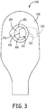
- FIG. 3 is a top view of an ostomy bag 250 having a filter assembly 300 in accordance with one embodiment.
- the ostomy bag 250 includes a stoma opening 252 into an interior 254 of the bag.
- the opening 252 is surrounded by a flange 256, which is where the ostomy bag will be connected to the user's stoma.
- the bag 250 also defines a vent opening 260.
- the filter 300 is secured to an interior side of the ostomy bag 250, so that the filter covers the vent opening 260.
- the outline of the filter 300 is visible through the stoma opening 252, and is shown in dashed lines where it is hidden by a top layer of the ostomy bag.
- the filter 300 has a bag side that is secured to the bag, and an outer side, which is opposite to the bag side.
- the outer side 302 is visible in FIG. 3 through the stoma opening, as well as in FIG. 5
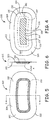
- FIG. 4 is a plan view of the bag side 304 of the filter 300.
- FIG. 6 is a cross-sectional view of the filter 300 along line 6-6 in FIG. 5 .
- the filter includes an adsorbent layer 310, a first layer 320 and an adhesive layer 330.
- the first layer 320 has an outer perimeter 322, an outer side 324 and a bag side 326.
- the adhesive layer 330 has an outer adhesive perimeter 332 and an inner adhesive perimeter 334, as well as an outer side 338 and a bag side 340.
- the inner perimeter 334 defines an exit window 336, through which gases will exit from the ostomy bag.
- An outer perimeter 312 of the adsorbent layer is shown in dashed lines through the adhesive layer.
- the bag side 314 of the filter layer or adsorbent layer 310 is visible in FIG. 4 through the exit window 336.
- the bag side 304 of the filter 300 includes two areas that are important for the attachment process: an adhesive zone 350 and a weld area 360.
- the adhesive zone 350 is defined on the bag side 340 of the adhesive layer 330.
- the adhesive zone includes pressure sensitive adhesive in one embodiment.
- the adhesive layer 330 is a pressure sensitive tape.
- a pressure sensitive double-sided tape that is suitable for the filter assembly described herein is 3M 9495 LE, Double Sided Tape available from 3M of St. Paul, Minnesota.
- the weld area 360 completely surrounds the adhesive zone. In one embodiment, the weld area is adjacent to the adhesive zone along the outer adhesive perimeter 332. In one embodiment, the weld area is continuously adjacent to, but not overlapping, the adhesive zone. In the embodiment of FIGS. 4-7 , the weld area both completely surrounds the adhesive zone, and partially overlaps the adhesive zone along the outer adhesive perimeter 332.
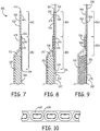
- FIG. 7 is a cross-sectional view of the filter 300, enlarged to show Detail A in FIG. 6 , and showing the adsorbent layer 310, the first layer 320 and the adhesive layer 330.
- the adhesive layer 330 includes a pressure-sensitive adhesive on both the outer side 338 and the bag side 340. The adhesive on the bag side of the adhesive layer is used to secure the adsorbent layer to the assembly and to secure the first layer to the assembly.
- the width of the adhesive zone is at least 1.5 mm in one embodiment, and at least 2 mm in another embodiment. In one example, the adhesive zone is 6 mm wide, and in another, 8 mm wide. In one embodiment, the width of the adhesive zone is at most 15 mm wide, and in another, 20 mm wide.
- the dimensions of the first layer, and therefore of the outer perimeter of the overall filter assembly can vary based on the size of the enclosure that is being vented, based on the size of the vent opening and many other factors.
- the first layer has a width of at least 5 mm, at least 10 mm, and at least 15 mm. In one embodiment, the first layer has a width of 23 mm, and in another 20 mm. In one embodiment, the width of the first layer is at most 30 mm, and in another, at most 40 mm. In various embodiments, the first layer has a length of at least 10 mm, at least 20 mm, and at least 20 mm. In one embodiment, the first layer has a width of 35 mm, and in another 38 mm.
- the width of the first layer is at most 45 mm, and in another, at most 50 mm.
- the first layer has a thickness of at least 0.5 mils (0.013 mm) in one embodiment, and at most 35 mils (0.9 mm) in one embodiment.
- FIG. 8 is a cross-sectional view similar to FIG. 7 , but showing the filter 300 welded to a bag 250.
- the vent opening 260 is present in the bag 250, and is positioned to align with the exit window 336 of the adhesive layer 330.
- An inner adhesive perimeter 334 surrounds and defines an exit window 336, from which gases exit the filter assembly.
- the adhesive zone 350 overlaps an outer perimeter 312 of the adsorbent layer 310. As a result, the adhesive zone 350 prevents the bypass of the adsorbent layer 310 during use.
- adhesive is also present on an outer side 338 of the adhesive layer 330. This adhesive area secures the adsorbent layer to the first layer, and can prevent bypass of the adsorbent layer.
- FIG. 9 is a cross-sectional view similar to FIG. 8 , but showing a second embodiment of a filter assembly 500 having a second gas permeable layer 501, which is also liquid impermeable.
- the filter assembly 500 has a bag side 504 and an outer side 502.
- the filter assembly also includes an adsorbent layer 510, a first layer 520 and an adhesive layer 530.
- the adsorbent layer 510 is sandwiched between the first layer 520 and the second layer 501.
- the adhesive layer 530 is present between the second layer 501 and the adsorbent layer 510, so that an adhesive zone 550 is present on the bag side 504 of the filter assembly 500.
- the filter assembly 500 also defines a weld zone 560 where the filter assembly 500 is welded to the bag.
- the second layer of the filter assembly is also microporous and liquid impermeable.
- the second layer includes expanded polytetrafluoroethylene (PTFE).
- the second layer is a laminate including a PTFE layer and a scrim layer.
- the second layer has a thickness of at least 0.1 mil (0.0025 mm) in one embodiment, and at most 15 mil (0.38 mm) in one embodiment.
- the second layer has a thickness of at least 0.5 mils (0.013 mm) in one embodiment, and at most 5 mil (0.13 mm) in one embodiment.
- the inclusion of the second layer can serve to prevent liquid from entering the ostomy bag or other enclosure. This can be especially useful if the user wears the bag while showering, bathing or engaged in similar activities.
- a filter assembly without a second layer can be provided with a different method of protection against liquid entering the bag.
- the user can be provided with a sealing sticker that is liquid impermeable to place over the vent opening while engaged in such activities.
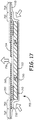
- FIG. 17 is a cross-sectional view of a filter assembly 700 positioned on an enclosure wall 250, where the filter assembly has a lateral flow path through a filter layer or adsorbent layer 710.
- the filter assembly 700 includes a first layer 720 and an adhesive layer 730.
- An adhesive zone 750 is defined by the adhesive layer 730.
- a weld zone 760 is defined outside of the adhesive zone 750 and surrounding the adhesive zone 740, where the first layer can be sealed to the enclosure wall 250.
- the enclosure wall 250 defines a vent opening 260.
- the first barrier layer 722 is positioned on an outer side of the adsorbent layer 710, so that gas cannot enter along that side of the adsorbent layer 710. Instead, gas must enter along a perimeter edge of the adsorbent layer 710, and flow laterally toward the center of the adsorbent layer.
- the second barrier layer 724 defines an exit opening 736 near the center of the filter assembly, through which gas can flow to exit the filter assembly.
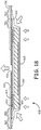
- FIG. 18 is a cross-sectional view of a filter assembly 800 positioned on an enclosure wall 250 having an exit opening 260, where the filter assembly permits air flow in both axial and lateral paths through a filter layer or adsorbent layer 810.
- the filter assembly 800 includes a first layer 820 and an adhesive layer 830.
- An adhesive zone 850 is defined by the adhesive layer.
- a weld zone 860 is defined outside of the adhesive zone 850 and surrounding the adhesive zone 850, where the first layer can be sealed to the enclosure wall 250.
- Two gas impermeable barriers 822, 824 are used to guide the gases toward a lateral flow path, but also permit a more axial flow path.
- the first barrier layer 822 is positioned on a central portion of an outer side of the adsorbent layer 810, so that gas can enter only along a perimeter edge of the adsorbent layer 810, or along an outer portion of the outer side of the adsorbent layer. The gases then flow laterally or axially and laterally toward the center of the adsorbent layer.
- the second barrier layer 824 defines an exit opening 836 through which gas can flow.
- FIGS. are not drawn to scale, in order to illustrate the various layers more clearly.
- the barrier layers of FIGS. 17 and 18 are relatively thin compared to the rest of the layers in the assembly.
- An example of a barrier film for use as a first barrier layer and a second barrier layer in the embodiments of FIGS. 17 and 18 is a film of polyethylene terephthalate (PET) having a thickness of at least 0.5 mil (0.013 mm).
- PET film has a thickness of not more than 2 mil (0.05 mm), 3 mil (0.76 mm), and 5 mil (0.13 mm).
- FIG. 10 is a top view of a release liner 600 with multiple filter assemblies 610 positioned on the release liner. An adhesive zone on the side of the filter assemblies that is contacting the release liners holds the filter assemblies to the release liner.
- an ostomy bag 250 ( FIG. 3 ) is provided, where the ostomy bag is configured to contain bodily waste products.
- the ostomy bag includes a stoma opening 252, an interior surface 254, an exterior surface 255 and a vent opening 260.
- a filter assembly such as filter assembly 300 or 500, is provided on a release liner 600.
- the filter assembly has a bag side and an outer side opposite from the bag side.
- the bag side of the filter includes an adhesive zone in which adhesive is present, where the adhesive zone has an outer perimeter.
- the adhesive zone may also have an inner perimeter that surrounds an exit window for gases from the ostomy bag.
- the filter assembly also includes a weld area that at least partially surrounds the adhesive zone, where the filter assembly is heat sealable to the bag.
- the filter assembly is removed from the release liner to reveal the adhesive zone on the bag side of the filter.
- the filter is then placed on the ostomy bag over the vent opening, so that the bag side of the filter and the adhesive zone contacts the bag surrounding the vent opening.
- some pressure is used when placing the filter on the bag, so that the adhesive is activated to secure the filter to the bag, forming a preliminary seal.
- a permanent seal is formed between the filter and the bag.
- the permanent seal may be formed by heat sealing.
- the adhesive holds the filter in the correct position during the assembly process, and then the heat seal creates the permanent seal to prevent gaseous or liquid by-pass of the filter assembly.
- the heat seal is accomplished by applying heat to the first layer, so that it creates a bond with the bag material.
- the bag side of the ostomy filter is adhered to an interior surface 254 of the ostomy bag over a vent opening in the bag. In another embodiment, the bag side of the ostomy filter is adhered to an exterior surface 255 of the ostomy bag over a vent opening in the bag.
- the embodiments of the present invention allow for a convenient and efficient assembly method with a highly reliable seal between the bag and the filter assembly.
- One of the most convenient ways of connecting an ostomy filter to an ostomy bag would be to use only a pressure-sensitive adhesive to create the seal between the bag and the filter. With only pressure-sensitive adhesive and no heat seal, there is no need for the equipment that is used to create the seal.
- ostomy bags are typically made with materials having a low surface energy, such as ethylene vinyl acetate (EVA) plastic, because the low surface energy of the material makes it easy to completely empty the bag when necessary. But the low surface energy of the bag material causes concern that the pressure-sensitive adhesive seal will not be reliable. Any leakage at the filter assembly would be unacceptable.
- EVA ethylene vinyl acetate
- the adhesive provides a seal around the adsorbent layer, while the heat seal provides a further safeguard against solid or liquid leakage. Since the adhesive is providing a seal around the adsorbent layer, there are fewer constraints on the shape and size of the heat welded area, so these embodiments also allow greater design freedom for different part shapes and sizes.
- the adsorbent layer or filter media described herein utilizes a fiber matrix into which activated carbon particles or fibers are incorporated.
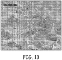
- FIGS. 11 to 13 scanning electron micrographs (SEM's) of electrospun polymeric fine fibers are shown. These fine fibers are also referred to as nanofibers. No additional binders or other non-active materials are generally needed to construct the activated carbon and fiber matrix. As the micrographs depict, binding the particles with fine fiber minimizes void space, resulting in a near optimal adsorption capacity per given volume while providing the tortuous path necessary for the gases to diffuse.
- the soft, strong, and flexible nature of the fine fiber makes the activated carbon and fiber matrix an ideal structure for use as a wearable adsorbent / absorbent.
- a fiber matrix that can be used is described in Published PCT Patent Application WO2007/095363 .
- the fiber has a diameter of about 0.001 to about 2 microns, 0.001 to about 1 micron, 0.001 to about 0.5 micron, or 0.001 to about 5 microns,
- a variety of techniques can be used for the manufacture of small diameter fine fibers.
- One method involves passing polymeric material through a fine capillary or opening either as a melted material or in a solution that is subsequently evaporated.
- Fibers can also be formed by using "spinnerets" typical for the manufacture of synthetic fiber such as nylon.
- Electrostatic spinning is often the method of choice for forming the fine fiber nonwoven webs of the invention.
- Such techniques involve the use of a hypodermic needle, nozzle, capillary or movable emitter. These structures provide liquid solutions of the polymer that are then attracted to a collection zone by a high voltage electrostatic field. As the materials are pulled from the emitter and accelerate through the electrostatic zone, the fiber becomes very thin and can be formed in a fiber structure by solvent evaporation.
- meltblown fibers typically useable according to the present invention are an air laid continuous extrusion of fibers joined to each other to form a sheet of layer of filter material.
- the adsorbent particles of the present invention can be substantially uniformly dispersed in the fine fiber web.
- Plastics such as polypropylene, polystyrene, and polyester may be used.
- particles are incorporated into the fine fiber nonwovens generally by feeding the particles into a flow of polymer solution using a volumetric screw feeder with an auger.
- a deflocculator to divide agglomerated particles.
- the particles are then deposited along with the polymer solution and become entangled within the fine fiber network as it forms upon drying of the polymer solution.
- the particles are activated carbon.
- Various embodiments allow use of a web comprising fine fiber and reactive, adsorptive or absorptive, inert or chemically modified particulates.
- Chemical modification is in the form of chemical or thermal treatment of the polymers, fibers and/or particulates or in the form of chemical impregnation of the particulates. It also includes mixing impregnates within the fiber/particulate web. Fluid passing through the web (typically a gas) interacts with the chemically- or thermally-modified web constituents.
- the active particulates can react with, absorb, or adsorb a portion of the fluid. It can allow selective chemical reactions of particular compounds or species in the fluid with other compounds or species attracted to or trapped on the surface.
- the surface of the particulates can also play the role of a catalyst through providing active sites that catalytically alter the material that passes through the web.
- the particulates may be impregnated with a single or several impregnates, such as impregnation of activated carbon with sodium hydroxide alone for H 2 S removal or impregnation of a mixture of sodium hydroxide and potassium iodide.
- This latter composition has a higher adsorption capacity and efficiency for removal of H 2 S than activated carbon impregnated with sodium hydroxide.
- the potassium iodide enhances the action of the sodium hydroxide catalytically or synergistically. Potassium iodide plays the role of oxidant which promotes oxidation of H 2 S to sulfur.
- the concepts taught herein can be applied as ostomy bag filters for H 2 S removal where the web with its constituents in this invention will provide the conditions required for ostomy bag filters such as low flow, low pressure drop, high H 2 S capacity.
- Other usable impregnates include citric acid, potassium hydroxide, potassium carbonate, sodium carbonate, potassium bicarbonate, sodium bicarbonate, and/or moisture, among others. Those compounds can be either impregnated on the particulates or mixed with the web constituents.
- a few examples of impregnates on activated carbons and their applications include: Activated carbons impregnated with potassium carbonate for the removal of acid gases (HCl, HF, SO 2 , H 2 S, NO 2 ); activated carbons impregnated with potassium iodide for the removal of H 2 S and PH 3 ; activated carbons impregnated with iron oxide for the removal of H 2 S and mercaptan; and activated carbons impregnated with potassium permanganate for the removal of H 2 S from oxygen-lacking gases.
- the use of a combination of particulates with different impregnates within the web for different applications is also appropriate in certain implementations. For example, it is possible to use of a mixture of two activated carbons.
- Water can be stored on the carbon surface or within the web through pre- humidification or through the use of impregnates or additional adsorbents that attract water vapor to their surfaces during the application.
- adsorbents can be used to cover the desired ranges of humidity and they include molecular sieves, activated alumina, silica gel and activated carbons. These adsorbent can be further modified by oxidation, heating, or impregnation. Impregnation is commonly done with alkali metals sulfate, citric acid, alkali metals carbonates, alkali metals bicarbonates, lithium and sodium chlorides, calcium chloride, and/or a mixture thereof.
- water adsorbent particles that will be capable of picking up water at low humidity or storing it. These water adsorbent particles can release some of their humidity in dry conditions. The presence of the released water can then enhance H 2 S removal in dry conditions.
- Imparting reactive activity to the particles and web after forming the fibrous web and structure can be accomplished using various different coating processes. For example, spray coating, dip coating, aerosol deposition, chemical vapor deposition, and vacuum coating.
- a final step can involve a drying process that may, or may not, include thermal treatments, gas purging, or vacuum methods.
- the chemistry of the walls of the first layer can be made to adsorb acidic, basic, and organic and water vapors, as well as several specific classes of compounds including reactive carbonyl compounds, such as formaldehyde, acetaldehyde and acetone.
- the reactive materials can be held together with adhesive or fibers to encapsulate, or simply hold, the particles. Also, additional scrim materials can be attached to hold the reactive material in place and minimize shedding of particles.
- the reactive material can also be sandwiched between layers of scrim. The scrim can help to produce the channels or space between the layers. This can be accomplished with a high loft scrim material that gives the proper spacing as well as ability to hold all the reactive particles in the media.
- a functional layer can be a coating or a separately formed layer of material.
- microporous layers, foam layers, expanded polytetrafluoroethylene layers, water repellent layers or coatings, odor masking layers or coatings, or a combination thereof may be provided on one or both sides of the nonwoven fine fiber composite webs of the invention.
- Such additional layers can add additional functionality to the web when that functionality is not practical to build into the web as it is formed. For example, for providing adhesion of the web onto a substrate, it may be desirable not to provide a fluorochemical coating to the web. But where oil repellency is desirable in the application, fluorochemicals provide the requisite protection.
- H 2 S breakthrough times were used to measure filter life based upon British Standard BS 7127 Part 101 and/or ASTM D5160-95, both of which are gas-phase adsorption tests of activated carbon.
- Pressure drop testing generally involved testing pressure drop across a media. In conducting the pressure drop test, a 1 square inch piece of media was tested at an airflow of about 500 cc/min and the pressure drop from one side of the media to the other was measured.
- Table 1 below provides H 2 S breakthrough times for a filter with activated carbon and fiber matrix constructed in accordance with the concepts described herein, in comparison to a selection of commercially available products. As previously described, it is desirable to have extended H 2 S breakthrough time and minimal pressure drop due to airflow.
- Comparative Media 1 was an activated carbon with a mean particle size of about 300 micron, ball hardness of 97, less than 20 percent by weight impregnate, web thickness of 1.7 mm and carbon basis weight of 400 gm/m 2 .
- Comparative Media 2 was obtained from an ostomy pouch sold with product number 411491 by ConvaTec, which has a headquarters location in Princeton, NJ.
- Comparative Media 3 was obtained from a Coloplast ostomy pouch with product number 14357, sold by Coloplast Corp. of Minneapolis, MN.
- Comparative Media 4 was obtained from an ostomy pouch number 18193 sold by Hollister Incorporated of Libertyville, IL. H 2 S tests were conducted on parts without any preconditioning beyond ambient conditions of RH or temperature.
- Table 2 provides pressure drop results for the filter media constructed with activated carbon and fiber matrix and the same comparative medias described with reference to Table 1. It is desirable to have a low pressure drop to reduce or eliminate ostomy bag ballooning. Pressure drop was measured (in-wg) at 500 cc/min of air flow. Table 2 Media Pressure drop (inches water gauge) Activated carbon and fiber matrix 260 g/m 2 2 Comparative Media 1 1 Comparative Media 2 11 Comparative Media 3 32 Comparative Media 4 5
- Table 3 presents the construction details of the above mentioned test samples.
- Table 3 activated carbon and fiber matrix 260 g/m 2 Shape Round Gas Flow Axial, (Through Face of Media) Material Described in U.S. Published Patent Application 2007/707761 Inlet Inside Face of Filter Outlet Outside Face of Filter Comparative Media 1 Shape Round Gas Flow Laterally through media Material Carbon with Binder between two Scrims Inlet Outside Perimeter Outlet Center Comparative Media 2 Shape Round Gas Flow Laterally through media Material Carbon on foam Inlet Outside Perimeter Outlet Center Comparative Media 3 Shape Crescent Gas Flow Laterally through media Material Carbon on Foam Inlet Right End Outlet Left End Comparative Media 4 Shape Crescent Gas Flow Laterally through media Material Carbon and Felt Inlet Perimeter Outlet Outside Face
- a nonwoven fine fiber composite web made in accordance with the description herein was produced using carbon particles impregnated with potassium iodine and potassium carbonate and elastomeric polyurethane.
- the polyurethane was obtained from Lubrizol Corporation (of Cleveland, OH) as was identified as SP-80A-150 and a lot # CD7NRAZ7Z.
- the polyurethane elastomer was dissolved in ethyl alcohol at 60 °C by vigorous stirring for 5-6 hours until the solids were completely dissolved, followed by cooling to 25 °C overnight.
- the solids content of the solution was 13.5 % by weight and the viscosity of the resulting solution was around 200 cP as measured using a Brookfield viscometer.
- This polymer solution was electrospun. During the electrospinning, carbon powder (209C Kina carbon, 80x200 mesh size, available from Calgon Carbon Corporation of Columbus, OH) was constantly weighed and fed at a steady feed rate into the flow of polymer solution using a volumetric screw feeder with an auger. The flow rate was metered to provide about 130 g/m 2 of carbon powder into the finished composite web.
- the particles were then fed into a deflocculator, which imparted sufficient momentum to the particles enabling them to deposit onto the collector. This was accomplished using compressed air at the deflocculator. In this manner, the particles and fibers were deposited simultaneously, creating an intermixed composite. A total of 130 g/m 2 of carbon powder were incorporated inside the fine fiber composite and the polyurethane fibers weighed about 7 g/m 2 .
- Example 2 In the same manner as described in Example 1, another nonwoven fine fiber composite web was generated using the same fine fiber materials and particles, but with a higher particle loading rate. A total of 260 g/m 2 of carbon powder were incorporated inside the fine fiber composite and the polyurethane fibers weighed about 14 g/m 2 .
- Example 2 In the same manner as described in Example 1, another nonwoven fine fiber composite web was generated using the same fine fiber materials and particles. A total of 390 g/m 2 of carbon powder were incorporated inside the fine fiber composite and the polyurethane fibers weighed about 21 g/m 2 .
- Example 2 The sample generated in Example 2 was calendared to the extent that a thickness reduction of 33 percent was achieved in the sample.
- the calendaring was achieved by pressing the fine fiber composite matrix between a roller and a hard surface to reduce thickness.
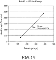
- H 2 S breakthrough performance of Examples 1-4 above are shown in FIG. 14 .
- the influence of basis weight on H 2 S performance is demonstrated, showing an increase in breakthrough performance observed with increasing basis weight of fine fiber composite matrices.
- the 260 gm/m 2 fine fiber composite matrices there was no observed lack of influence on H 2 S performance from calendaring.
- FIG. 15 demonstrates the influence of test gas relative humidity on two basis weights of activated carbon and fiber matrix. As is apparent from FIG. 15 , the breakthrough time increased with both materials as relative humidity increased.
- Table 4 shows a comparison between activated carbon and fiber matrix media compared to a non impregnated activated carbon based media. Airflow was set at 500 cc/min using an H 2 S challenge concentration at 25 ppm H 2 S and 35 percent relative humidity. The breakthrough time was measured at the point the concentration of H 2 S reached 2ppm Table 4 Media Breakthrough time (minutes) activated carbon and fiber matrix 130 g/m 2 260 Non impregnated media 5
- Activated carbon and fiber matrix media contain various proportions of activated carbon.
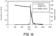
- FIG. 16 shows the thermal analysis of activated carbon and fiber matrix media. The sample was heated to 600 °C in N 2 atmosphere at a rate of 10 °C/min then maintained at an isothermal for 30 minutes followed by heating in air to 1000 °C at 10°C/min. Analysis of the data shows that 90 percent of the tested activated carbon and fiber matrix media is composed of activated carbon while 7 percent of the weight is web based and the rest are ash and inorganic residue.
- the web in activated carbon and fiber matrix media does not block the pores and the surface area of the particles.
- the porous structure as well as the surface area of the activated carbon and fiber matrix media in Example 12 was measured using nitrogen adsorption isotherms.
- the structural parameters of the activated carbon and fiber matrix material were compared to those of the constituent activated carbon.
- a variety of benefits are realized through the use of activated carbon and fiber matrix-based adsorbent breather filter for use with an ostomy bag.
- This configuration provides a structure that allows the use of carbon particles less than 150 micron in one dimension.
- the small carbon particle size provides greater exposure of the activated carbon to the contaminant intended to be adsorbed, which produces a higher efficiency filter per given volume.
- the small amount of fine fiber used as a binder allows for a larger percentage of the utilized space to be occupied by adsorbent allowing for near optimal capacity.
- Binders utilized in standard carbon filter construction can block 30 to 50 percent of the activated carbon adsorption sites. An activated carbon and fiber matrix does not require use of a binder.
- the adsorbent layer is substantially free of any binder.
- the adsorbent layer can contain 2% or less binder material by weight.
- a filter constructed in this fashion has a lower space requirement and hence can lead to reduced product size and cost.
- axial flow through thin filter layers can result in minimizing pressure drop.
- the simplified filter construction can eliminate extra film layers meant to promote radial flow.
- a wide variety of filter profiles such as round, crescent, rectangular, etc. can be accomplished.
- the low pressure drop and high efficiency allow the filter to be constructed with airflow through the face of the filter media which also allows an expanded polytetrafluoroethylene (ePTFE) filter media to be added to the top (outer or inlet), and if desired, to the bottom (bag or exit), side of the filter.
- ePTFE expanded polytetrafluoroethylene
- the value of this construction is that the ePTFE can be added without the extra penalty of pressure drop due to a small filter area that a radial flow design would create.
- the flexibility and thin profile of the activated carbon and fiber matrix based filter will allow the ostomy product to conform more closely to the patient's body.
- Example 12 As a further analysis to support Example 12, a H 2 S breakthrough comparison of media made in accordance with the present invention was performed to analyze any negative influence of the fine fibers.
- This test analyzed the H 2 S performance of a 22mm diameter 390 g/m 2 activated carbon-containing the fine fiber web described by this invention in comparison with a loose fill constructed to the same dimensions and using an equivalent amount of the same activated carbon.
- the results in Table 6 demonstrate that there was no improvement in the part without the fine fiber.
- the loose fill part H 2 S time was lower than the 390 g/m 2 activated carbon-containing fine fiber.
Landscapes
- Health & Medical Sciences (AREA)
- Engineering & Computer Science (AREA)
- Chemical & Material Sciences (AREA)
- Chemical Kinetics & Catalysis (AREA)
- Biomedical Technology (AREA)
- Epidemiology (AREA)
- Nursing (AREA)
- Orthopedic Medicine & Surgery (AREA)
- Heart & Thoracic Surgery (AREA)
- Vascular Medicine (AREA)
- Life Sciences & Earth Sciences (AREA)
- Animal Behavior & Ethology (AREA)
- General Health & Medical Sciences (AREA)
- Public Health (AREA)
- Veterinary Medicine (AREA)
- Mechanical Engineering (AREA)
- Orthopedics, Nursing, And Contraception (AREA)
Claims (15)
- Filteranordnung (300; 500; 700; 800) für eine Umhüllung (250), umfassend:eine Umhüllung-Seite (304, 504) und eine äußere Seite (302; 502), welche der Umhüllung-Seite entgegengesetzt ist;eine erste Schicht (320; 520; 720; 820), welche an der äußeren Seite der Filteranordnung Gas-durchlässig positioniert ist; undeine adsorbierende Schicht (310; 510; 710; 810), wobei die adsorbierende Schicht adsorbierende Partikel und ein Gittermaterial umfasst, welches die adsorbierenden Partikel an Ort und Stelle hält, wobei die erste Schicht (320; 520; 720; 820) an einer äußeren Fläche der adsorbierenden Schicht positioniert ist; undwobei die Umhüllung-Seite der Filteranordnung umfasst:eine adhäsive Zone (350; 550; 750; 850), in welcher ein Adhäsiv vorhanden ist, welches einen äußeren Adhäsiv-Umfang (332) und einen inneren Adhäsiv-Umfang (334) aufweist, welches einen Austritt-Fenster-Abschnitt (336) definiert, welcher vollständig von der adhäsiven Zone (350; 550; 750, 850) umgeben ist;einen Schweißbereich (360; 560; 760; 860), welcher vollständig von der adhäsiven Zone (350; 550; 750; 850) umgeben ist, wobei die erste Schicht (320; 520; 720; 820) der Filteranordnung (300; 500; 700; 800) auf ein Material, welches Kunststoff umfasst, an dem Schweißbereich (360; 560; 760; 860) Wärme-abdichtbar ist;wobei die adsorbierende Schicht (310; 510; 710; 810) die adsorbierenden Partikel in einem feinen Fasernetz verteilt umfasst.
- Filteranordnung (300, 500, 700, 800) nach Anspruch 1, wobei das Adhäsiv ein Druck-sensitives Adhäsiv ist.
- Filteranordnung (300, 500, 700, 800) nach Anspruch 1 oder 2, wobei die erste Schicht (320, 520, 720, 820) microporös ist.
- Filteranordnung (300, 500, 700, 800) nach einem vorhergehenden Anspruch, wobei die erste Schicht (320, 520, 720, 820) Flüssigkeit-undurchlässig ist.
- Filteranordnung (300, 500, 700, 800) nach Anspruch 1, wobei die Schicht aktivierten Kohlenstoffs und des feinen Faser-Gitters im Wesentlichen frei von einem Binder-Material ist.
- Filteranordnung (300, 500, 700, 800) nach Anspruch 1, wobei die adsorbierende Schicht (310, 510, 710, 810) etwa 1 bis 30 Gewichtsprozent feine Faser mit einem Faser-Durchmesser von etwa 0,001 bis 5 µm und 70 bis 99 Gewichtsprozent adsorbierende Partikel umfasst.
- Filteranordnung (300, 500, 700, 800) nach Anspruch 1, wobei die erste Schicht (320, 520, 720, 820) ein Laminat eines expandierten PTFE und eine Gitterschicht umfasst.
- Filteranordnung (500) nach Anspruch 1, ferner umfassend eine zweite Schicht (501), welche Gas-durchlässig ist, wobei die adsorbierende Schicht (510) zwischen der ersten Schicht (520) und der zweiten Schicht (501) eingefasst ist; wobei optional die zweite Schicht (501) Flüssigkeit-undurchlässig ist.
- Filteranordnung (500) nach Anspruch 1, wobei der Schweißbereich (360; 560; 760; 860) der adhäsiven Zone (350; 550; 750; 850) entlang des gesamten äußeren Umfangs der adhäsiven Zone benachbart ist, oder wobei der Schweißbereich (360; 560; 760; 860) teilweise die adhäsive Zone (350; 550; 750; 850) entlang des äußeren Umfangs der adhäsiven Zone überlappt.
- Kombination, umfassend den Filter nach einem vorhergehenden Anspruch, welcher an einer Umhüllung (250) angebracht ist, umfassend Kunststoff.
- Kombination nach Anspruch 10, wobei die Umhüllung (250) ein flexibler Beutel ist.
- Kombination nach Anspruch 10, wobei die Umhüllung (250) ein Stoma-Beutel ist.
- Verfahren zum Anbringen einer Filteranordnung (300; 500; 700; 800) nach einem der Ansprüche 1 bis 9 an einem Umhüllung-Beutel (250), umfassend Kunststoff, über einer Belüftung-Öffnung (260) in dem Umhüllung-Beutel, umfassend:Bereitstellen eines Umhüllung-Beutels (250), welcher eine Belüftung-Öffnung (260) umfasst; undBereitstellen einer Filteranordnung (300; 500; 700; 800) nach einem der Ansprüche 1 bis 9 an einer Löse-Auskleidung,Entfernen der Filteranordnung (300) von der Löse-Auskleidung, um die adhäsive Zone (350; 550; 750; 850) freizulegen;Platzieren der Filteranordnung (300; 500; 700; 800) an dem Umhüllung-Beutel (250) über der Belüftung-Öffnung (260); undnach dem Platzieren des Filters (300; 500; 700; 800) an dem Umhüllung-Beutel (250), Bilden einer permanenten Dichtung zwischen der Filteranordnung (300; 500; 700; 800) und dem Umhüllung-Beutel (250).
- Verfahren nach Anspruch 13, wobei das Adhäsiv ein Druck-sensitives ist, so dass der Schritt des Platzierens der Filteranordnung (300; 500; 700; 800) an dem Umhüllung-Beutel (250) das Adhäsiv aktiviert, um eine vorläufige Dichtung zu bilden.
- Verfahren nach Anspruch 13 oder 14, wobei die permanente Dichtung in der Schweißzone durch Wärme-Abdichtung gebildet wird.
Applications Claiming Priority (4)
| Application Number | Priority Date | Filing Date | Title |
|---|---|---|---|
| US4124408P | 2008-04-01 | 2008-04-01 | |
| US12/414,951 US8979811B2 (en) | 2008-04-01 | 2009-03-31 | Enclosure ventilation filter and assembly method |
| PCT/US2009/039148 WO2009146076A2 (en) | 2008-04-01 | 2009-04-01 | Enclosure ventilation filter and assembly method |
| EP09755439.8A EP2274068B1 (de) | 2008-04-01 | 2009-04-01 | Verschlussentlüftungsfilter und verfahren zu seiner herstellung |
Related Parent Applications (1)
| Application Number | Title | Priority Date | Filing Date |
|---|---|---|---|
| EP09755439.8A Division EP2274068B1 (de) | 2008-04-01 | 2009-04-01 | Verschlussentlüftungsfilter und verfahren zu seiner herstellung |
Publications (2)
| Publication Number | Publication Date |
|---|---|
| EP3028684A1 EP3028684A1 (de) | 2016-06-08 |
| EP3028684B1 true EP3028684B1 (de) | 2020-09-16 |
Family
ID=41118281
Family Applications (2)
| Application Number | Title | Priority Date | Filing Date |
|---|---|---|---|
| EP16150548.2A Active EP3028684B1 (de) | 2008-04-01 | 2009-04-01 | Verschlussentlüftungsfilter und montageverfahren |
| EP09755439.8A Active EP2274068B1 (de) | 2008-04-01 | 2009-04-01 | Verschlussentlüftungsfilter und verfahren zu seiner herstellung |
Family Applications After (1)
| Application Number | Title | Priority Date | Filing Date |
|---|---|---|---|
| EP09755439.8A Active EP2274068B1 (de) | 2008-04-01 | 2009-04-01 | Verschlussentlüftungsfilter und verfahren zu seiner herstellung |
Country Status (4)
| Country | Link |
|---|---|
| US (1) | US8979811B2 (de) |
| EP (2) | EP3028684B1 (de) |
| CN (1) | CN101990455B (de) |
| WO (1) | WO2009146076A2 (de) |
Families Citing this family (91)
| Publication number | Priority date | Publication date | Assignee | Title |
|---|---|---|---|---|
| WO2008134334A1 (en) | 2007-04-24 | 2008-11-06 | Bristol-Myers Squibb Company | Closure system for a drainable pouch |
| BRPI0812404A2 (pt) | 2007-06-12 | 2014-12-02 | Convatec Technologies Inc | Dispositivo de ostomia |
| US8361044B2 (en) * | 2008-03-14 | 2013-01-29 | Mary Marshall Enterprises, Inc. | Methods and devices for concealing and securing a urine collection bag |
| US9078760B2 (en) | 2008-03-14 | 2015-07-14 | Mary L. Marshall Enterprises, Inc. | Devices for concealing a urine collection bag and that provide access to monitor and manipulate a urine collection bag therein |
| US10646370B2 (en) * | 2008-04-01 | 2020-05-12 | Donaldson Company, Inc. | Enclosure ventilation filter and assembly method |
| AU2009316291B2 (en) | 2008-11-19 | 2015-09-17 | Convatec Technologies Inc. | Ostomy pouch appliance |
| AU2010270603B2 (en) | 2009-07-07 | 2015-05-07 | Convatec Technologies Inc. | Pressure sensitive silicone adhesives with amphiphilic copolymers |
| CN102470304B (zh) | 2009-07-22 | 2016-01-20 | 唐纳森公司 | 使用ptfe膜以及碳网片用于hepa效率以及气味控制的过滤介质构造 |
| AU2010292291B2 (en) | 2009-09-11 | 2016-06-09 | Convatec Technologies Inc. | Controlled discharge ostomy appliance and shield therefor |
| EP2575704B1 (de) * | 2010-06-04 | 2016-09-14 | Coloplast A/S | Ostomiebeutel mit filterkonstruktion |
| EP2582337A2 (de) * | 2010-06-16 | 2013-04-24 | ISKIA GmbH & Co. KG | Vorrichtung zur wundbehandlung und wundabdeckpflaster |
| WO2012044910A1 (en) * | 2010-09-30 | 2012-04-05 | Convatec Technologies Inc. | Ostomy pouch with filtering system |
| US10285847B2 (en) * | 2011-09-29 | 2019-05-14 | Convatec Technologies Inc. | Ostomy pouch with filtering system |
| US8776832B2 (en) * | 2010-12-09 | 2014-07-15 | Donaldson Company, Inc. | Valve for electronic enclosure |
| US9999536B2 (en) * | 2010-12-27 | 2018-06-19 | Benson Turtleneck Barrier Llc | Ostomy barrier seal |
| CN102744036B (zh) * | 2011-04-18 | 2014-07-09 | 香港科技大学 | 复合吸附剂材料及其制备方法和应用 |
| GB201115160D0 (en) | 2011-09-02 | 2011-10-19 | Trio Healthcare Ltd | Discharge solidifier and malodour control |
| USD761955S1 (en) | 2012-05-29 | 2016-07-19 | Mary L. Marshall | Urinary bag cover and support |
| US9317068B2 (en) | 2012-09-24 | 2016-04-19 | Donaldson Company, Inc. | Venting assembly and microporous membrane composite |
| JP6121174B2 (ja) * | 2013-01-22 | 2017-04-26 | 株式会社ディスコ | 梱包材 |
| GB201317667D0 (en) * | 2013-10-07 | 2013-11-20 | Welland Medical Ltd | Support film |
| CN103638746B (zh) * | 2013-12-17 | 2015-06-03 | 佛山市斯乐普特种材料有限公司 | 高效低阻纺粘非织造滤料、及其生产设备和制造方法 |
| GB2549060B (en) * | 2014-01-22 | 2020-09-23 | Welland Medical Ltd | Ostomy bag filter with adhesive webbing |
| US10531977B2 (en) | 2014-04-17 | 2020-01-14 | Coloplast A/S | Thermoresponsive skin barrier appliances |
| WO2015164832A1 (en) | 2014-04-24 | 2015-10-29 | Convatec Technologies Inc. | Ostomy pouch filter system |
| CN107530594A (zh) * | 2015-04-07 | 2018-01-02 | 唐纳森公司 | 用于电子器件外壳的再循环过滤器 |
| US20170007439A1 (en) * | 2015-07-10 | 2017-01-12 | Thomas J. Boksan | Ostomy Appliance Collar |
| CN108026496B (zh) * | 2015-10-01 | 2022-07-26 | 思拓凡瑞典有限公司 | 过滤器保持装置 |
| EP3362010B1 (de) | 2015-10-14 | 2023-09-20 | ConvaTec Technologies Inc. | Medizinische vorrichtung mit einem öffnungssystem |
| US11141100B2 (en) | 2015-12-23 | 2021-10-12 | Coloplast A/S | Moisture assessment system and method for wound care |
| US10464285B2 (en) * | 2016-01-29 | 2019-11-05 | Panasonic Intellectual Property Management Co., Ltd. | Laminate and manufacturing method thereof |
| GB201609954D0 (en) * | 2016-06-07 | 2016-07-20 | Monty Stephanie | A dressing |
| JP6955878B2 (ja) * | 2017-03-17 | 2021-10-27 | 東洋アルミエコープロダクツ株式会社 | フィルター |
| JP6955879B2 (ja) * | 2017-03-17 | 2021-10-27 | 東洋アルミエコープロダクツ株式会社 | フィルター及びフィルター構造体 |
| GB201715388D0 (en) * | 2017-09-22 | 2017-11-08 | Salts Healthcare Ltd | An ostomy appliance |
| US10849781B2 (en) * | 2017-12-22 | 2020-12-01 | Coloplast A/S | Base plate for an ostomy appliance |
| AU2018391393B2 (en) * | 2017-12-22 | 2024-08-22 | Coloplast A/S | Coupling part with a hinge for an ostomy base plate and sensor assembly part |
| EP4074291A1 (de) | 2017-12-22 | 2022-10-19 | Coloplast A/S | Grundplatte für eine stomavorrichtung |
| JP7282781B2 (ja) * | 2017-12-22 | 2023-05-29 | コロプラスト アクティーゼルスカブ | 角度範囲漏出検出機能を備えるオストミー装具 |
| LT3727227T (lt) * | 2017-12-22 | 2023-07-25 | Coloplast A/S | Ostomijos prietaiso pagrindo plokštė ir pagrindo plokštės jutiklių montavimo dalis ir pagrindo plokštės ir jutiklių montavimo dalies gamybos būdas |
| WO2019120425A1 (en) | 2017-12-22 | 2019-06-27 | Coloplast A/S | Ostomy appliance system, monitor device, and method of monitoring an ostomy appliance |
| WO2019120443A1 (en) * | 2017-12-22 | 2019-06-27 | Coloplast A/S | Sensor assembly part and a base plate for an ostomy appliance and a method for manufacturing a base plate or a sensor assembly part |
| WO2019120434A1 (en) | 2017-12-22 | 2019-06-27 | Coloplast A/S | Processing schemes for an ostomy system, monitor device for an ostomy appliance and related methods |
| EP3996106B1 (de) | 2017-12-22 | 2025-10-22 | Coloplast A/S | Überwachungsvorrichtung eines stomasystems und zugehöriges verfahren zum betrieb einer überwachungsvorrichtung |
| US11471318B2 (en) | 2017-12-22 | 2022-10-18 | Coloplast A/S | Data collection schemes for a medical appliance and related methods |
| US11627891B2 (en) | 2017-12-22 | 2023-04-18 | Coloplast A/S | Calibration methods for medical appliance tools |
| EP3727245B1 (de) | 2017-12-22 | 2025-04-30 | Coloplast A/S | Datenübertragungsschemata für ein stomasystem, überwachungsvorrichtung für eine stomavorrichtung und zugehörige verfahren |
| US11590015B2 (en) * | 2017-12-22 | 2023-02-28 | Coloplast A/S | Sensor assembly part and a base plate for a medical appliance and a method for manufacturing a sensor assembly part and a base plate |
| WO2019120445A1 (en) | 2017-12-22 | 2019-06-27 | Coloplast A/S | Base plate and sensor assembly of an ostomy system having a leakage sensor |
| DK3727240T4 (da) | 2017-12-22 | 2025-03-24 | Coloplast As | Hjælpeanordninger til et stomisystem og tilhørende fremgangsmåder til kommunikering af funktionstilstand |
| US11918506B2 (en) | 2017-12-22 | 2024-03-05 | Coloplast A/S | Medical appliance with selective sensor points and related methods |
| US10500084B2 (en) | 2017-12-22 | 2019-12-10 | Coloplast A/S | Accessory devices of an ostomy system, and related methods for communicating leakage state |
| US10799385B2 (en) | 2017-12-22 | 2020-10-13 | Coloplast A/S | Ostomy appliance with layered base plate |
| EP3727226B1 (de) | 2017-12-22 | 2024-08-21 | Coloplast A/S | Stomavorrichtung und überwachungsvorrichtung mit winkelleckdetektion |
| US11998473B2 (en) | 2017-12-22 | 2024-06-04 | Coloplast A/S | Tools and methods for cutting holes in a medical appliance |
| EP4595934A3 (de) | 2017-12-22 | 2025-11-05 | Coloplast A/S | Überwachungsvorrichtung für ein stomasystem mit einem verbinder zur verbindung mit einer grundplatte und einer zubehörvorrichtung |
| WO2019120442A1 (en) | 2017-12-22 | 2019-06-27 | Coloplast A/S | Sensor assembly part and a base plate for an ostomy appliance and a device for connecting to a base plate or a sensor assembly part |
| EP4275663A3 (de) | 2017-12-22 | 2024-01-17 | Coloplast A/S | Feuchtigkeitsdetektierende grundplatte für eine stomavorrichtung und system zur bestimmung der feuchtigkeitsausbreitung in einer grundplatte und/oder einem sensorbauteil |
| EP3727222B1 (de) | 2017-12-22 | 2024-05-08 | Coloplast A/S | Sensorbauteil für künstlichen darmausgang und verfahren zur herstellung eines sensorbauteils |
| CN111447896B (zh) | 2017-12-22 | 2023-03-28 | 科洛普拉斯特公司 | 用于造口术器具的底板、用于造口术器具的监测装置和系统 |
| WO2019120451A1 (en) * | 2017-12-22 | 2019-06-27 | Coloplast A/S | Base plate and a sensor assembly part for an ostomy appliance and a method for manufacturing a base plate and sensor assembly part |
| EP3755282B1 (de) | 2018-02-20 | 2024-05-08 | Coloplast A/S | Sensorbauteil und grundplatte für eine stomavorrichtung und vorrichtung zur verbindung mit einer grundplatte und/oder einem sensorbauteil |
| EP3755286B1 (de) | 2018-02-20 | 2025-04-30 | Coloplast A/S | Zubehörgeräte für ein stomasystem und zugehörige verfahren zum wechseln einer stomavorrichtung auf der grundlage eines zukünftigen betriebszustands |
| EP3755283B1 (de) | 2018-02-20 | 2024-05-01 | Coloplast A/S | Sensorbaugruppenteil und eine grundplatte und ein stomabeutel für eine stomavorrichtung und vorrichtung zum anschluss an eine grundplatte und/oder ein sensorbaugruppenteil |
| EP3764960B1 (de) | 2018-03-15 | 2023-12-06 | Coloplast A/S | Vorrichtung und verfahren zur bestimmung der tragezeit eines stomas basierend auf standortdaten |
| WO2019174698A1 (en) | 2018-03-15 | 2019-09-19 | Coloplast A/S | Methods of configuring ostomy notifications and related accessory devices |
| LT3764956T (lt) | 2018-03-15 | 2022-08-10 | Coloplast A/S | Ostomijos prietaiso likusio nusidėvėjimo laiko valdymo būdai ir susiję papildomi įtaisai |
| LT3764961T (lt) | 2018-03-15 | 2024-03-25 | Coloplast A/S | Aparatas ir būdai ostomijos prietaiso vartotojo navigacijai į persisirengimo kambarį |
| EP4233808B1 (de) * | 2018-07-10 | 2024-04-10 | Hollister Incorporated | Stomabeutelfilter |
| JP7460603B2 (ja) | 2018-08-15 | 2024-04-02 | コロプラスト アクティーゼルスカブ | オストミーシステムの付属デバイス及び問題識別の関連方法 |
| US11344835B2 (en) | 2018-08-21 | 2022-05-31 | Donaldson Company, Inc. | Filter assembly for an enclosure |
| US12186227B2 (en) * | 2018-12-13 | 2025-01-07 | Julia Menifee | Urostomy bag and absorbent insert system |
| US12165312B2 (en) | 2018-12-20 | 2024-12-10 | Coloplast A/S | Ostomy condition classification with masking, devices and related methods |
| CN113194891A (zh) | 2018-12-20 | 2021-07-30 | 科洛普拉斯特公司 | 利用图像数据变换进行造口术状况分类的装置和相关方法 |
| WO2020156626A1 (en) | 2019-01-31 | 2020-08-06 | Coloplast A/S | A sensor patch for an ostomy appliance |
| US11517469B2 (en) | 2019-01-31 | 2022-12-06 | Coloplast A/S | Base plate and sensor assembly part of an ostomy system having a moisture sensor |
| CN113365582B (zh) | 2019-01-31 | 2024-12-31 | 科洛普拉斯特公司 | 造口传感器贴片 |
| CN113365581B (zh) | 2019-01-31 | 2024-12-31 | 科洛普拉斯特公司 | 造口传感器贴片的应用 |
| US11612512B2 (en) | 2019-01-31 | 2023-03-28 | Coloplast A/S | Moisture detecting base plate for an ostomy appliance and a system for determining moisture propagation in a base plate and/or a sensor assembly part |
| US11737906B2 (en) | 2019-02-07 | 2023-08-29 | Convatec Technologies, Inc. | Adjustable convex ostomy device |
| US12257172B2 (en) | 2019-02-28 | 2025-03-25 | Coloplast A/S | Sensor patch for attachment to a base plate |
| US11590017B2 (en) | 2019-04-25 | 2023-02-28 | Convatec Technologies Inc. | Ostomy wafers incorporating adhesives, ostomy devices including the same, and methods of applying ostomy wafers and ostomy devices |
| SG11202111676UA (en) | 2019-04-25 | 2021-11-29 | Convatec Technologies Inc | Ostomy wafers incorporating adhesives and foam layers, devices including the same, and methods of applying |
| JP7526202B2 (ja) | 2019-04-25 | 2024-07-31 | コンバテック・テクノロジーズ・インコーポレイテッド | 穴あきチャンバのオストミーウェハ、それを含むオストミー装置、及びオストミーウェハとオストミー装置の接着方法 |
| CN114080204B (zh) * | 2019-06-14 | 2025-08-05 | 霍利斯特公司 | 造口术器具的渗漏检测系统 |
| CN110921749B (zh) * | 2019-12-17 | 2020-12-15 | 南京大学 | 一种可伸缩气浮集气罩及其在粘胶纤维废水处理中的应用 |
| EP4125745A1 (de) * | 2020-03-30 | 2023-02-08 | Donaldson Company, Inc. | Ostomiebeutelfilter |
| US12147357B2 (en) | 2020-04-14 | 2024-11-19 | Coloplast A/S | Personal care system with monitor device and related methods |
| WO2021242603A1 (en) * | 2020-05-27 | 2021-12-02 | Hollister Incorporated | Ostomy leakage detection system |
| GB2626947A (en) * | 2023-02-07 | 2024-08-14 | Salts Healthcare Ltd | Ostomy appliance including a filter |
| EP4661811A1 (de) | 2023-02-10 | 2025-12-17 | ConvaTec Technologies Inc. | Verbesserungen an ostomievorrichtungen |
Citations (2)
| Publication number | Priority date | Publication date | Assignee | Title |
|---|---|---|---|---|
| US4490145A (en) * | 1983-06-27 | 1984-12-25 | E. R. Squibb & Sons, Inc. | Ostomy pouch with deodorizing filter |
| WO2007095363A2 (en) * | 2006-02-13 | 2007-08-23 | Donaldson Company, Inc. | Filter web comprising fine fiber and reactive, adsorptive or absorptive particulate |
Family Cites Families (32)
| Publication number | Priority date | Publication date | Assignee | Title |
|---|---|---|---|---|
| US420445A (en) * | 1890-02-04 | Soluble nitro-cellulose and process of manufacture | ||
| US3952727A (en) * | 1973-09-27 | 1976-04-27 | Hollister Incorporated | Vent device for ostomy appliance |
| US4318406A (en) * | 1976-07-06 | 1982-03-09 | Matburn (Holdings) Limited | Colostomy or ileastomy applicance |
| GB1596496A (en) * | 1976-07-06 | 1981-08-26 | Matburn Holdings Ltd | Filter for a colostomy or ileostomy appliance and a method of manufacture therefor |
| US4203445A (en) | 1978-12-11 | 1980-05-20 | Hollister Incorporated | Gas-venting filter assembly for collection device |
| US4274848A (en) * | 1979-09-24 | 1981-06-23 | Hollister Incorporated | Gas-venting filter for collection appliance |
| GB2177604B (en) * | 1985-07-15 | 1989-07-19 | Craig Med Prod Ltd | Ostomy bags, particularly ileostomy bags, and gas filter arrangements for same |
| DK158133C (da) | 1986-01-31 | 1990-08-27 | Coloplast As | Deodoriseringsfilter til stomiudstyr, navnlig til stomiposer |
| NZ227995A (en) * | 1988-03-07 | 1991-12-23 | Squibb & Sons Inc | Ostomy bag with filter: intervening wall has scattered holes |
| GB2221854B (en) | 1988-08-15 | 1992-08-12 | Squibb & Sons Inc | Ostomy bag and gas filter for same |
| US4957522A (en) * | 1989-06-06 | 1990-09-18 | Brassell Gilbert W | Combination of a filter and a material permeable to gases but impermeable to liquids |
| US5085652A (en) * | 1989-06-16 | 1992-02-04 | E. R. Squibb & Sons | Pouch with mounting member for removable adhesive filter |
| US5250042A (en) * | 1990-02-20 | 1993-10-05 | E. R. Squibb & Sons, Inc. | Ostomy bag with filter combination |
| GB9202360D0 (en) | 1992-02-04 | 1992-03-18 | Gore W L & Ass Uk | Ostomy filter |
| GB9207007D0 (en) * | 1992-03-28 | 1992-05-13 | Smiths Industries Plc | Medico-surgical collection bags |
| US5306264A (en) * | 1993-01-14 | 1994-04-26 | E. R. Squibb & Sons, Inc. | Ostomy bag with multi-stage filter |
| GB2290712B (en) * | 1994-07-01 | 1998-03-25 | Welland Medical Ltd | Ostomy bag filters |
| US5417678A (en) * | 1994-07-15 | 1995-05-23 | Minnesota Mining And Manufacturing Company | Low profile ostomy filter |
| US5952422A (en) * | 1995-12-20 | 1999-09-14 | Bristol-Myers Squibb Company | Polyurethane pressure-sensitive adhesives |
| GB2302028B (en) | 1996-08-29 | 1997-08-27 | Bristol Myers Squibb Co | Production of filter elements |
| CN1230137C (zh) | 1997-04-08 | 2005-12-07 | 科洛普拉斯特公司 | 造口用具 |
| US6359100B1 (en) * | 1998-01-28 | 2002-03-19 | Bristol-Myers Squibb Company | Methods of preparing polyurethane adhesives, adhesives produced thereby and medical devices employing the same |
| GB2351238B (en) * | 1998-08-13 | 2001-10-24 | Bristol Myers Squibb Co | Adhesive wafer for ostomy pouch |
| US6506184B1 (en) * | 1999-05-11 | 2003-01-14 | Dansac A/S | Venting/filter assembly, bag incorporating same and method of venting flatus gasses |
| US7244482B2 (en) * | 2000-06-28 | 2007-07-17 | Coloplast A/S | Method for welding components of a multi-layer construction |
| JP2003010226A (ja) * | 2001-06-29 | 2003-01-14 | Alcare Co Ltd | 排泄物収容装具 |
| DK175870B1 (da) * | 2001-09-05 | 2005-05-02 | Coloplast As | Stomiindretning |
| US7291208B2 (en) * | 2004-08-13 | 2007-11-06 | Gore Enterprise Holdings, Inc. | Grooved active and passive adsorbent filters |
| US7326190B2 (en) * | 2005-05-25 | 2008-02-05 | Hollister Incorporated | Ostomy pouch and high performance deodorizing gas filter assembly therefor |
| US20070049880A1 (en) * | 2005-08-23 | 2007-03-01 | Bristol-Myers Squibb Company | Filter assembly for an ostomy device |
| WO2007030703A2 (en) | 2005-09-09 | 2007-03-15 | Donaldson Company, Inc. | Adsorbent ostomy bag vent |
| GB2434316B (en) * | 2006-01-24 | 2010-02-17 | Welland Medical Ltd | Ostomy bag |
-
2009
- 2009-03-31 US US12/414,951 patent/US8979811B2/en active Active
- 2009-04-01 WO PCT/US2009/039148 patent/WO2009146076A2/en not_active Ceased
- 2009-04-01 EP EP16150548.2A patent/EP3028684B1/de active Active
- 2009-04-01 EP EP09755439.8A patent/EP2274068B1/de active Active
- 2009-04-01 CN CN200980112883.2A patent/CN101990455B/zh active Active
Patent Citations (2)
| Publication number | Priority date | Publication date | Assignee | Title |
|---|---|---|---|---|
| US4490145A (en) * | 1983-06-27 | 1984-12-25 | E. R. Squibb & Sons, Inc. | Ostomy pouch with deodorizing filter |
| WO2007095363A2 (en) * | 2006-02-13 | 2007-08-23 | Donaldson Company, Inc. | Filter web comprising fine fiber and reactive, adsorptive or absorptive particulate |
Also Published As
| Publication number | Publication date |
|---|---|
| EP3028684A1 (de) | 2016-06-08 |
| US20090247970A1 (en) | 2009-10-01 |
| WO2009146076A3 (en) | 2010-01-21 |
| EP2274068A2 (de) | 2011-01-19 |
| CN101990455A (zh) | 2011-03-23 |
| WO2009146076A2 (en) | 2009-12-03 |
| EP2274068B1 (de) | 2016-01-13 |
| CN101990455B (zh) | 2016-08-31 |
| US8979811B2 (en) | 2015-03-17 |
| EP2274068A4 (de) | 2012-10-31 |
Similar Documents
| Publication | Publication Date | Title |
|---|---|---|
| US12233001B2 (en) | Enclosure ventilation filter | |
| EP3028684B1 (de) | Verschlussentlüftungsfilter und montageverfahren | |
| CN1230137C (zh) | 造口用具 | |
| EP1051955B1 (de) | Entlüftungs-/Filteranordnung, Beutel mit dieser Anordnung und Verfahren zum Entlüften von Blähungen | |
| US7371270B2 (en) | Odour absorbing filters | |
| CA1233383A (en) | Ostomy pouch with deodorizing filter | |
| JPH0432096Y2 (de) | ||
| JP4546084B2 (ja) | 造孔器具 | |
| EP0443728B2 (de) | Ostomiebeutel mit Filter Einrichtung | |
| US20230137568A1 (en) | Ostomy bag filter | |
| EP1514528B1 (de) | Entlüftungs-/Filteranordnung zum Entlüften von Blähungen | |
| JP4205239B2 (ja) | ガス吸着シート | |
| JP3544928B2 (ja) | 脱臭フィルター付き排泄物収容装具 | |
| EP1380333B1 (de) | Geruchabsorbierende Filter | |
| RU2384311C2 (ru) | Фильтр, снабженный отверстием для удаления газов, и пакет для сбора физиологических жидкостей | |
| JP2017051378A (ja) | 消臭部材およびその利用 | |
| JPH06270308A (ja) | 活性無機粉体シートからなる中空構造板 |
Legal Events
| Date | Code | Title | Description |
|---|---|---|---|
| PUAI | Public reference made under article 153(3) epc to a published international application that has entered the european phase |
Free format text: ORIGINAL CODE: 0009012 |
|
| AC | Divisional application: reference to earlier application |
Ref document number: 2274068 Country of ref document: EP Kind code of ref document: P |
|
| AK | Designated contracting states |
Kind code of ref document: A1 Designated state(s): AT BE BG CH CY CZ DE DK EE ES FI FR GB GR HR HU IE IS IT LI LT LU LV MC MK MT NL NO PL PT RO SE SI SK TR |
|
| STAA | Information on the status of an ep patent application or granted ep patent |
Free format text: STATUS: REQUEST FOR EXAMINATION WAS MADE |
|
| RIN1 | Information on inventor provided before grant (corrected) |
Inventor name: DALLAS, ANDREW J. Inventor name: ELSAYED, YEHYA A. Inventor name: HEBERT, MICHAEL J. Inventor name: KELENY, LLOYD G Inventor name: KALAYCI, VELI E. Inventor name: MULDER, DAVID W. |
|
| 17P | Request for examination filed |
Effective date: 20161207 |
|
| RBV | Designated contracting states (corrected) |
Designated state(s): AT BE BG CH CY CZ DE DK EE ES FI FR GB GR HR HU IE IS IT LI LT LU LV MC MK MT NL NO PL PT RO SE SI SK TR |
|
| STAA | Information on the status of an ep patent application or granted ep patent |
Free format text: STATUS: EXAMINATION IS IN PROGRESS |
|
| 17Q | First examination report despatched |
Effective date: 20170302 |
|
| GRAP | Despatch of communication of intention to grant a patent |
Free format text: ORIGINAL CODE: EPIDOSNIGR1 |
|
| STAA | Information on the status of an ep patent application or granted ep patent |
Free format text: STATUS: GRANT OF PATENT IS INTENDED |
|
| INTG | Intention to grant announced |
Effective date: 20200408 |
|
| RIN1 | Information on inventor provided before grant (corrected) |
Inventor name: KALAYCI, VELI E. Inventor name: MULDER, DAVID W. Inventor name: ELSAYED, YEHYA A. Inventor name: HEBERT, MICHAEL J. Inventor name: DALLAS, ANDREW J. Inventor name: KELENY, LLOYD G |
|
| GRAS | Grant fee paid |
Free format text: ORIGINAL CODE: EPIDOSNIGR3 |
|
| GRAA | (expected) grant |
Free format text: ORIGINAL CODE: 0009210 |
|
| STAA | Information on the status of an ep patent application or granted ep patent |
Free format text: STATUS: THE PATENT HAS BEEN GRANTED |
|
| AC | Divisional application: reference to earlier application |
Ref document number: 2274068 Country of ref document: EP Kind code of ref document: P |
|
| AK | Designated contracting states |
Kind code of ref document: B1 Designated state(s): AT BE BG CH CY CZ DE DK EE ES FI FR GB GR HR HU IE IS IT LI LT LU LV MC MK MT NL NO PL PT RO SE SI SK TR |
|
| REG | Reference to a national code |
Ref country code: GB Ref legal event code: FG4D |
|
| REG | Reference to a national code |
Ref country code: CH Ref legal event code: EP |
|
| REG | Reference to a national code |
Ref country code: DE Ref legal event code: R096 Ref document number: 602009062787 Country of ref document: DE |
|
| REG | Reference to a national code |
Ref country code: IE Ref legal event code: FG4D |
|
| REG | Reference to a national code |
Ref country code: AT Ref legal event code: REF Ref document number: 1313462 Country of ref document: AT Kind code of ref document: T Effective date: 20201015 |
|
| PG25 | Lapsed in a contracting state [announced via postgrant information from national office to epo] |
Ref country code: SE Free format text: LAPSE BECAUSE OF FAILURE TO SUBMIT A TRANSLATION OF THE DESCRIPTION OR TO PAY THE FEE WITHIN THE PRESCRIBED TIME-LIMIT Effective date: 20200916 Ref country code: GR Free format text: LAPSE BECAUSE OF FAILURE TO SUBMIT A TRANSLATION OF THE DESCRIPTION OR TO PAY THE FEE WITHIN THE PRESCRIBED TIME-LIMIT Effective date: 20201217 Ref country code: BG Free format text: LAPSE BECAUSE OF FAILURE TO SUBMIT A TRANSLATION OF THE DESCRIPTION OR TO PAY THE FEE WITHIN THE PRESCRIBED TIME-LIMIT Effective date: 20201216 Ref country code: HR Free format text: LAPSE BECAUSE OF FAILURE TO SUBMIT A TRANSLATION OF THE DESCRIPTION OR TO PAY THE FEE WITHIN THE PRESCRIBED TIME-LIMIT Effective date: 20200916 Ref country code: FI Free format text: LAPSE BECAUSE OF FAILURE TO SUBMIT A TRANSLATION OF THE DESCRIPTION OR TO PAY THE FEE WITHIN THE PRESCRIBED TIME-LIMIT Effective date: 20200916 Ref country code: NO Free format text: LAPSE BECAUSE OF FAILURE TO SUBMIT A TRANSLATION OF THE DESCRIPTION OR TO PAY THE FEE WITHIN THE PRESCRIBED TIME-LIMIT Effective date: 20201216 |
|
| REG | Reference to a national code |
Ref country code: AT Ref legal event code: MK05 Ref document number: 1313462 Country of ref document: AT Kind code of ref document: T Effective date: 20200916 |
|
| REG | Reference to a national code |
Ref country code: NL Ref legal event code: MP Effective date: 20200916 |
|
| PG25 | Lapsed in a contracting state [announced via postgrant information from national office to epo] |
Ref country code: LV Free format text: LAPSE BECAUSE OF FAILURE TO SUBMIT A TRANSLATION OF THE DESCRIPTION OR TO PAY THE FEE WITHIN THE PRESCRIBED TIME-LIMIT Effective date: 20200916 |
|
| REG | Reference to a national code |
Ref country code: LT Ref legal event code: MG4D |
|
| PG25 | Lapsed in a contracting state [announced via postgrant information from national office to epo] |
Ref country code: CZ Free format text: LAPSE BECAUSE OF FAILURE TO SUBMIT A TRANSLATION OF THE DESCRIPTION OR TO PAY THE FEE WITHIN THE PRESCRIBED TIME-LIMIT Effective date: 20200916 Ref country code: NL Free format text: LAPSE BECAUSE OF FAILURE TO SUBMIT A TRANSLATION OF THE DESCRIPTION OR TO PAY THE FEE WITHIN THE PRESCRIBED TIME-LIMIT Effective date: 20200916 Ref country code: LT Free format text: LAPSE BECAUSE OF FAILURE TO SUBMIT A TRANSLATION OF THE DESCRIPTION OR TO PAY THE FEE WITHIN THE PRESCRIBED TIME-LIMIT Effective date: 20200916 Ref country code: RO Free format text: LAPSE BECAUSE OF FAILURE TO SUBMIT A TRANSLATION OF THE DESCRIPTION OR TO PAY THE FEE WITHIN THE PRESCRIBED TIME-LIMIT Effective date: 20200916 Ref country code: PT Free format text: LAPSE BECAUSE OF FAILURE TO SUBMIT A TRANSLATION OF THE DESCRIPTION OR TO PAY THE FEE WITHIN THE PRESCRIBED TIME-LIMIT Effective date: 20210118 Ref country code: EE Free format text: LAPSE BECAUSE OF FAILURE TO SUBMIT A TRANSLATION OF THE DESCRIPTION OR TO PAY THE FEE WITHIN THE PRESCRIBED TIME-LIMIT Effective date: 20200916 |
|
| PG25 | Lapsed in a contracting state [announced via postgrant information from national office to epo] |
Ref country code: PL Free format text: LAPSE BECAUSE OF FAILURE TO SUBMIT A TRANSLATION OF THE DESCRIPTION OR TO PAY THE FEE WITHIN THE PRESCRIBED TIME-LIMIT Effective date: 20200916 Ref country code: IS Free format text: LAPSE BECAUSE OF FAILURE TO SUBMIT A TRANSLATION OF THE DESCRIPTION OR TO PAY THE FEE WITHIN THE PRESCRIBED TIME-LIMIT Effective date: 20210116 Ref country code: ES Free format text: LAPSE BECAUSE OF FAILURE TO SUBMIT A TRANSLATION OF THE DESCRIPTION OR TO PAY THE FEE WITHIN THE PRESCRIBED TIME-LIMIT Effective date: 20200916 Ref country code: AT Free format text: LAPSE BECAUSE OF FAILURE TO SUBMIT A TRANSLATION OF THE DESCRIPTION OR TO PAY THE FEE WITHIN THE PRESCRIBED TIME-LIMIT Effective date: 20200916 |
|
| REG | Reference to a national code |
Ref country code: DE Ref legal event code: R097 Ref document number: 602009062787 Country of ref document: DE |
|
| PG25 | Lapsed in a contracting state [announced via postgrant information from national office to epo] |
Ref country code: SK Free format text: LAPSE BECAUSE OF FAILURE TO SUBMIT A TRANSLATION OF THE DESCRIPTION OR TO PAY THE FEE WITHIN THE PRESCRIBED TIME-LIMIT Effective date: 20200916 |
|
| PLBE | No opposition filed within time limit |
Free format text: ORIGINAL CODE: 0009261 |
|
| STAA | Information on the status of an ep patent application or granted ep patent |
Free format text: STATUS: NO OPPOSITION FILED WITHIN TIME LIMIT |
|
| 26N | No opposition filed |
Effective date: 20210617 |
|
| PG25 | Lapsed in a contracting state [announced via postgrant information from national office to epo] |
Ref country code: DK Free format text: LAPSE BECAUSE OF FAILURE TO SUBMIT A TRANSLATION OF THE DESCRIPTION OR TO PAY THE FEE WITHIN THE PRESCRIBED TIME-LIMIT Effective date: 20200916 Ref country code: SI Free format text: LAPSE BECAUSE OF FAILURE TO SUBMIT A TRANSLATION OF THE DESCRIPTION OR TO PAY THE FEE WITHIN THE PRESCRIBED TIME-LIMIT Effective date: 20200916 |
|
| PG25 | Lapsed in a contracting state [announced via postgrant information from national office to epo] |
Ref country code: IT Free format text: LAPSE BECAUSE OF FAILURE TO SUBMIT A TRANSLATION OF THE DESCRIPTION OR TO PAY THE FEE WITHIN THE PRESCRIBED TIME-LIMIT Effective date: 20200916 |
|
| PG25 | Lapsed in a contracting state [announced via postgrant information from national office to epo] |
Ref country code: MC Free format text: LAPSE BECAUSE OF FAILURE TO SUBMIT A TRANSLATION OF THE DESCRIPTION OR TO PAY THE FEE WITHIN THE PRESCRIBED TIME-LIMIT Effective date: 20200916 |
|
| PG25 | Lapsed in a contracting state [announced via postgrant information from national office to epo] |
Ref country code: LU Free format text: LAPSE BECAUSE OF NON-PAYMENT OF DUE FEES Effective date: 20210401 |
|
| REG | Reference to a national code |
Ref country code: BE Ref legal event code: MM Effective date: 20210430 |
|
| PG25 | Lapsed in a contracting state [announced via postgrant information from national office to epo] |
Ref country code: LI Free format text: LAPSE BECAUSE OF NON-PAYMENT OF DUE FEES Effective date: 20210430 Ref country code: CH Free format text: LAPSE BECAUSE OF NON-PAYMENT OF DUE FEES Effective date: 20210430 |
|
| PG25 | Lapsed in a contracting state [announced via postgrant information from national office to epo] |
Ref country code: IE Free format text: LAPSE BECAUSE OF NON-PAYMENT OF DUE FEES Effective date: 20210401 |
|
| PG25 | Lapsed in a contracting state [announced via postgrant information from national office to epo] |
Ref country code: IS Free format text: LAPSE BECAUSE OF FAILURE TO SUBMIT A TRANSLATION OF THE DESCRIPTION OR TO PAY THE FEE WITHIN THE PRESCRIBED TIME-LIMIT Effective date: 20210116 |
|
| PG25 | Lapsed in a contracting state [announced via postgrant information from national office to epo] |
Ref country code: BE Free format text: LAPSE BECAUSE OF NON-PAYMENT OF DUE FEES Effective date: 20210430 |
|
| PG25 | Lapsed in a contracting state [announced via postgrant information from national office to epo] |
Ref country code: HU Free format text: LAPSE BECAUSE OF FAILURE TO SUBMIT A TRANSLATION OF THE DESCRIPTION OR TO PAY THE FEE WITHIN THE PRESCRIBED TIME-LIMIT; INVALID AB INITIO Effective date: 20090401 Ref country code: CY Free format text: LAPSE BECAUSE OF FAILURE TO SUBMIT A TRANSLATION OF THE DESCRIPTION OR TO PAY THE FEE WITHIN THE PRESCRIBED TIME-LIMIT Effective date: 20200916 |
|
| P01 | Opt-out of the competence of the unified patent court (upc) registered |
Effective date: 20230413 |
|
| PG25 | Lapsed in a contracting state [announced via postgrant information from national office to epo] |
Ref country code: MK Free format text: LAPSE BECAUSE OF FAILURE TO SUBMIT A TRANSLATION OF THE DESCRIPTION OR TO PAY THE FEE WITHIN THE PRESCRIBED TIME-LIMIT Effective date: 20200916 |
|
| PG25 | Lapsed in a contracting state [announced via postgrant information from national office to epo] |
Ref country code: MT Free format text: LAPSE BECAUSE OF FAILURE TO SUBMIT A TRANSLATION OF THE DESCRIPTION OR TO PAY THE FEE WITHIN THE PRESCRIBED TIME-LIMIT Effective date: 20200916 |
|
| PGFP | Annual fee paid to national office [announced via postgrant information from national office to epo] |
Ref country code: FR Payment date: 20250319 Year of fee payment: 17 |
|
| PGFP | Annual fee paid to national office [announced via postgrant information from national office to epo] |
Ref country code: GB Payment date: 20250319 Year of fee payment: 17 |
|
| PGFP | Annual fee paid to national office [announced via postgrant information from national office to epo] |
Ref country code: DE Payment date: 20250319 Year of fee payment: 17 |
|
| PG25 | Lapsed in a contracting state [announced via postgrant information from national office to epo] |
Ref country code: TR Free format text: LAPSE BECAUSE OF FAILURE TO SUBMIT A TRANSLATION OF THE DESCRIPTION OR TO PAY THE FEE WITHIN THE PRESCRIBED TIME-LIMIT Effective date: 20200916 |