EP3028535B2 - Système de table de cuisson - Google Patents
Système de table de cuisson Download PDFInfo
- Publication number
- EP3028535B2 EP3028535B2 EP14766213.4A EP14766213A EP3028535B2 EP 3028535 B2 EP3028535 B2 EP 3028535B2 EP 14766213 A EP14766213 A EP 14766213A EP 3028535 B2 EP3028535 B2 EP 3028535B2
- Authority
- EP
- European Patent Office
- Prior art keywords
- heating
- virtual
- control unit
- operating mode
- heating elements
- Prior art date
- Legal status (The legal status is an assumption and is not a legal conclusion. Google has not performed a legal analysis and makes no representation as to the accuracy of the status listed.)
- Active
Links
- 238000010438 heat treatment Methods 0.000 claims description 229
- 230000008859 change Effects 0.000 claims description 8
- 238000000034 method Methods 0.000 claims description 5
- 230000007423 decrease Effects 0.000 claims description 3
- 230000001419 dependent effect Effects 0.000 claims description 3
- 238000010411 cooking Methods 0.000 description 90
- 230000006698 induction Effects 0.000 description 10
- 230000006870 function Effects 0.000 description 9
- 238000001514 detection method Methods 0.000 description 4
- 230000000694 effects Effects 0.000 description 3
- 230000008569 process Effects 0.000 description 3
- 230000001105 regulatory effect Effects 0.000 description 3
- 230000003213 activating effect Effects 0.000 description 2
- 230000002457 bidirectional effect Effects 0.000 description 2
- 230000001276 controlling effect Effects 0.000 description 2
- 230000005291 magnetic effect Effects 0.000 description 2
- 230000033228 biological regulation Effects 0.000 description 1
- 239000003990 capacitor Substances 0.000 description 1
- 239000004020 conductor Substances 0.000 description 1
- 238000013016 damping Methods 0.000 description 1
- 238000011161 development Methods 0.000 description 1
- 230000018109 developmental process Effects 0.000 description 1
- 230000005672 electromagnetic field Effects 0.000 description 1
- 230000005294 ferromagnetic effect Effects 0.000 description 1
- 230000002441 reversible effect Effects 0.000 description 1
Images
Classifications
-
- H—ELECTRICITY
- H05—ELECTRIC TECHNIQUES NOT OTHERWISE PROVIDED FOR
- H05B—ELECTRIC HEATING; ELECTRIC LIGHT SOURCES NOT OTHERWISE PROVIDED FOR; CIRCUIT ARRANGEMENTS FOR ELECTRIC LIGHT SOURCES, IN GENERAL
- H05B6/00—Heating by electric, magnetic or electromagnetic fields
- H05B6/02—Induction heating
- H05B6/06—Control, e.g. of temperature, of power
- H05B6/062—Control, e.g. of temperature, of power for cooking plates or the like
-
- H—ELECTRICITY
- H05—ELECTRIC TECHNIQUES NOT OTHERWISE PROVIDED FOR
- H05B—ELECTRIC HEATING; ELECTRIC LIGHT SOURCES NOT OTHERWISE PROVIDED FOR; CIRCUIT ARRANGEMENTS FOR ELECTRIC LIGHT SOURCES, IN GENERAL
- H05B3/00—Ohmic-resistance heating
- H05B3/68—Heating arrangements specially adapted for cooking plates or analogous hot-plates
-
- H—ELECTRICITY
- H05—ELECTRIC TECHNIQUES NOT OTHERWISE PROVIDED FOR
- H05B—ELECTRIC HEATING; ELECTRIC LIGHT SOURCES NOT OTHERWISE PROVIDED FOR; CIRCUIT ARRANGEMENTS FOR ELECTRIC LIGHT SOURCES, IN GENERAL
- H05B2203/00—Aspects relating to Ohmic resistive heating covered by group H05B3/00
- H05B2203/037—Heaters with zones of different power density
-
- H—ELECTRICITY
- H05—ELECTRIC TECHNIQUES NOT OTHERWISE PROVIDED FOR
- H05B—ELECTRIC HEATING; ELECTRIC LIGHT SOURCES NOT OTHERWISE PROVIDED FOR; CIRCUIT ARRANGEMENTS FOR ELECTRIC LIGHT SOURCES, IN GENERAL
- H05B2213/00—Aspects relating both to resistive heating and to induction heating, covered by H05B3/00 and H05B6/00
- H05B2213/03—Heating plates made out of a matrix of heating elements that can define heating areas adapted to cookware randomly placed on the heating plate
Definitions
- the invention is based on a hob device according to the preamble of claim 1.
- a hob device specifically an induction hob device, has already been proposed with a heating arrangement that has two heating elements that are arranged next to one another and are intended for heating cooking utensils that have been placed there, and with a control unit.
- the documents FR-A-2 863 039 and WO 2009/016124 A1 disclose prior art cooktop devices.
- the object of the invention is in particular to provide a generic device with improved properties with regard to a high level of comfort for an operator.
- the object is achieved according to the invention by the features of patent claim 1, while advantageous configurations and developments of the invention can be found in the dependent claims.
- the invention is based on a hob device, in particular an induction hob device, with at least one heating arrangement which has at least two, in particular at least three, advantageously at least four heating elements which are arranged next to one another and are intended at least for heating the cooking utensil that has been set up, and with at least one control unit .
- control unit be provided, at least in one operating mode, as a function of the size of at least one cooking utensil placed, to define a number of virtual heating zones with different heat output densities, with the virtual heating zones being formed by heating elements arranged next to one another, which are dependent on their number and /or size are suitable for operating the cookware.
- a "heating arrangement" is to be understood in particular as a unit with at least two, in particular at least three, advantageously at least four heating elements, which is defined by the arrangement of the heating elements.
- the hob device comprises at least two heating arrangements, each of which has at least two, in particular at least three, advantageously at least four heating elements.
- heating element is to be understood in particular as an element which is intended to, at least in one operating mode, transfer electrical energy at least to a large extent to a cooking utensil, preferably through at least one base body forming a cooking surface, and/or electrical energy into heat to convert, in particular to heat at least one set cooking utensil, preferably through at least one base body forming a cooking surface.
- the heating element is provided to transmit a power of at least 100 W, in particular at least 500 W, advantageously at least 1000 W, preferably at least 2000 W, in at least one operating mode in which the heating element is connected to supply electronics.
- the heating element is designed as an induction heating element.
- an “induction heating element” is to be understood in particular as a wound electrical conductor through which high-frequency alternating current flows in at least one operating mode.
- the induction heating element is intended to convert electrical energy into an alternating magnetic field, which is intended to cause eddy currents and/or magnetic reversal effects in a metallic, preferably at least partially ferromagnetic, cooking utensil, which are converted into heat.
- the induction heating element is preferably provided to cause the cooking utensil to heat up.
- the induction heating element is preferably provided to convert electrical energy into electromagnetic field energy in the operating mode, which energy is ultimately converted into heat in a suitable cooking utensil.
- the hob device has at least one base body at least for setting up cookware.
- the base body forms at least essentially a cooking surface.
- the phrase that two heating elements are arranged "next to one another" should be understood in particular to mean that a shortest straight line connecting the heating elements, starting from a first of the heating elements, only contains the first heating element and a second of the heating elements, which is formed separately from the first heating element. cuts, in particular while avoiding a further heating element between the two heating elements, wherein a distance of the further heating element to at least one of the adjacently arranged heating elements is at least as large as a distance between the adjacently arranged heating elements.
- control unit is to be understood in particular as an electronic unit which is preferably at least partially integrated in a control and/or regulating unit of a hob and which is preferably provided for controlling and/or regulating at least the heating elements.
- the control unit comprises an arithmetic unit and, in particular, in addition to the arithmetic unit, a memory unit with a control and/or regulation program stored therein, which is intended to be executed by the arithmetic unit.
- the hob device advantageously has at least one sensor unit, which is formed in particular by the heating elements themselves, which is intended to detect cooking utensil that has been set up, in particular by measuring at least one inductance and/or at least one capacitance.
- control unit is provided to evaluate measured values from the sensor unit, to calculate at least one heating zone and to define heating elements that form this heating zone.
- control unit is intended to assign a heating zone that is adapted in terms of shape, size and/or position to a detected cooking utensil.
- control unit is provided to enable at least one detection of a set-up cooking utensil by the sensor unit by activating at least one of the heating elements, in particular at least a large part of, advantageously all of the heating elements.
- other possibilities for detecting positioned cooking utensils that appear sensible to a person skilled in the art are conceivable.
- the sensor unit is intended to detect at least one size of the cooking utensil that has been set up.
- the control unit is intended to determine the size of a set cooking utensil by means of a number of heating elements covered by the cooking utensil.
- the control unit is provided to effect at least one regular detection of positioned cooking utensils, in particular by the sensor unit.
- control unit is intended to effect at least one “regular” detection of cooking utensil in place should be understood in particular to mean that the control unit is intended to detect cooking utensil in place at time intervals of less than 30 s, in particular of less than 10 s, advantageously less than 5 s, particularly advantageously less than 1 s, preferably less than 0.1 s.
- control unit is provided to subdivide a cooking surface area formed by the heating arrangement into a number of virtual heating zones, at least in one operating mode, in particular at least in the operating mode, depending on the size of at least one set cooking utensil.
- a number of virtual heating zones is inversely proportional to the size of the cooking utensil placed.
- the number of virtual heating zones decreases as the size of the cooking utensil increases.
- the control unit is intended to assign a first heating power density to a first virtual heating zone at least in one operating mode, in particular at least in the operating mode, and to define heating power densities of further virtual heating zones that differ from the first virtual heating zone as a function of the first heating power density.
- control unit is provided to assign a second heating power density, which differs in particular from the first heating power density of the first virtual heating zone, at least in one operating mode, in particular at least in the operating mode, to a second virtual heating zone that is separate from the first virtual heating zone .
- the phrase that the virtual heating zones are formed by heating elements arranged next to one another, which are "suitable" in terms of their number and/or size for operating the cooking utensil, is to be understood in particular that a number and/or size of the virtual heating zones are essentially is equal to a number and/or size of cooking utensils placed.
- control unit is provided to combine heating elements covered by one cooking utensil, in particular by precisely one first cooking utensil, to form a first heating zone.
- control unit is intended to divide the cooking surface area formed by the heating arrangement into a number of virtual heating zones, the size of which is essentially equal to a size of the first heating zone.
- the virtual heating zones are formed by essentially the same number of heating elements as the first heating zone.
- a size of the virtual heating zones is essentially equal to a size of the first heating zone.
- the control unit is provided to assign at least one heating element to at least two virtual heating zones when at least one cooking utensil is of a size that covers more than one heating element.
- At least one heating element is part of at least two virtual heating zones.
- “Provided” should be understood to mean, in particular, specially programmed, designed and/or equipped.
- the fact that an object is provided for a specific function is to be understood in particular to mean that the object fulfills and/or executes this specific function in at least one application and/or operating state.
- the configuration according to the invention makes it possible in particular to achieve a high level of comfort for an operator.
- an effective heating of the cooking utensil and/or an advantageous heat distribution can be achieved.
- an inexpensive and/or energy-saving configuration can be achieved.
- control unit is provided to operate the virtual heating zones as a function of the position at least in one operating mode, in particular at least in the operating mode, with predefined heating power densities that differ from one another.
- control unit is provided to assign a predefined heating power density to at least one, in particular a majority of, advantageously each of the virtual heating zones, which differs in particular from a predefined heating power density of further virtual heating zones.
- a predefined, individual heating power density is stored in the memory unit of the control unit for at least one, in particular a majority of, advantageously each of the virtual heating zones.
- At least one predefined heating power density of at least one virtual heating zone can be changed by an operator, in particular before the start of a cooking process and/or during a cooking process and/or after the end of a cooking process.
- the control unit is provided to change further heating power densities of further virtual heating zones depending on the change in the predefined heating power densities of the first virtual heating zone.
- the phrase that the control unit is intended to "assign" a heating power density to a virtual heating zone should be understood in particular to mean that the control unit is intended to operate the virtual heating zone with the heating power density that the virtual heating zone is activated when the virtual heating zone is activated assigned to the heating zone.
- control unit is intended to “operate” at least one virtual heating zone should be understood in particular to mean that the control unit is intended to control at least one electronic supply system that supplies the virtual heating zone.
- the supply electronics include at least one heating frequency unit for supplying at least one virtual heating zone.
- a "heating frequency unit” is to be understood in particular as an electrical unit that generates an oscillating electrical signal, preferably with a frequency of at least 1 kHz, in particular at least 10 kHz, advantageously at least 20 kHz and in particular at most 100 kHz for a heating element.
- the heating frequency unit is provided to provide a maximum electrical power of at least 1000 W, in particular at least 2000 W, advantageously at least 3000 W and preferably at least 3500 W, required by the heating element.
- the heating frequency unit comprises in particular at least one inverter, which preferably has at least two, preferably series-connected, bidirectional unipolar switches, which are formed in particular by a transistor and a diode connected in parallel, and particularly advantageously at least one damping capacitance each connected in parallel with the bidirectional unipolar switches, which is formed in particular by at least one capacitor.
- control unit be provided, at least in one operating mode, in particular at least in the operating mode, to assign a higher heating power density to a virtual heating zone arranged in an area facing an operator than to a virtual heating zone arranged in an operator remote area is arranged.
- control unit is provided, at least in one operating mode, to assign a lower heating power density to a virtual heating zone that is arranged in an area facing an operator than to a virtual heating zone that is arranged in an area facing away from an operator.
- control unit is provided to, at least in one operating mode, in particular at least in the operating mode, a virtual heating zone, which is arranged in the area facing an operator, a maximum heating power density of all virtual heating zones, in particular in a comparison with other virtual heating zones, at least one Assign cooking surface area.
- control unit is provided to, at least in one operating mode, in particular at least in the operating mode, a virtual heating zone that is arranged in the area facing away from an operator, a lowest heating power density of all virtual heating zones, in particular in a comparison with other virtual heating zones, at least one Assign cooking surface area.
- control unit is provided to assign different heating power densities to virtual heating zones depending on a distance from the area facing an operator, at least in one operating mode, in particular at least in the operating mode. In this way, in particular, a high level of comfort for an operator can be achieved.
- an operator can prepare food in the area facing the operator.
- an operator can place ready-to-cook food to keep it warm in the area facing away from the operator, in order to be able to continue to cook food comfortably, particularly in the area facing the operator.
- control unit is provided to switch between the operating mode and at least one additional operating mode, in particular at least two additional operating modes, depending on an operator input by means of at least one operating unit.
- control unit is provided to operate the heating elements with heating power densities that are independent of one another in at least a first further operating mode.
- heating power densities can be freely selected in the first additional operating mode, in particular while avoiding influencing other heating power densities of other heating elements.
- a first heating power density of a first heating element can be freely selected by an operator input using the operator control unit.
- a second heating power density of a second heating element can be freely selected by an operator input using the operating unit, in particular while avoiding influencing the first heating power density of the first heating element.
- the control unit is provided to operate the heating elements in at least a second additional operating mode, depending on the position, with predefined heating power densities that differ from one another.
- An "operator input" is to be understood in particular as an actuation of the operating unit by an operator. In this way, in particular, a flexible configuration can be achieved. In addition, an operator can advantageously easily switch between different operating modes at will.
- heating elements form a variable cooking surface area.
- heating elements of the heating arrangement form the variable cooking surface area.
- the heating arrangement is designed as a variable cooking surface area.
- a "variable cooking surface area" is to be understood in particular as a cooking surface area which is intended to form at least one cooking zone adapted to at least one set of cooking utensil.
- the variable cooking surface area differs from a cooking surface in which the heating zones are fixed, in particular by markings on the cooking surface.
- the variable cooking surface area is formed by at least two, in particular at least three, advantageously at least four heating elements.
- the heating elements forming the variable cooking surface area are arranged in a single row.
- a "row” is to be understood in particular as a row and/or a column and/or a strip.
- the heating elements are arranged on one another, in particular lined up, along a row longitudinal direction connecting the heating elements, which is in particular embodied as a straight line.
- the row longitudinal direction connects focal points of the heating elements. It is also conceivable that the heating elements are arranged in an offset manner, with the focal points of the heating elements being at a distance of less than 50% from a straight line which is aligned at least essentially parallel to the longitudinal direction of the row and which connects the heating elements to one another at least essentially in the middle.
- a "single" row of at least two heating elements is to be understood in particular as a row in which the heating elements are arranged adjacent in, in particular precisely, one longitudinal direction of the row, with the control unit being provided for connecting at least one of the heating elements arranged adjacent in the longitudinal direction of the row to at least to form a cooking zone adapted to a set up cooking utensil.
- At least one further heating element which is separate from the heating elements forming the row and is part of a further row separate from the row, is arranged at a distance from each of the heating elements forming the row.
- the further heating element is at a distance from each of the heating elements forming the row with respect to a row transverse direction, which is at least essentially perpendicular to the row longitudinal direction, which is greater than 15%, in particular greater than 30%, advantageously greater than 40%, preferably greater than 50%, particularly preferably greater than 75% of an amount of at least one extension, in particular a longitudinal extension and/or a transverse extension, of at least one of the heating elements forming the row.
- a straight line and/or plane is aligned “at least substantially perpendicularly” to another straight line and/or plane that is separate from the straight line and/or plane is to be understood in particular as meaning that the straight line and/or plane with the further straight line and/or plane in a projection onto at least one projection plane in which at least one of the straight lines and/or one of the planes is arranged, encloses an angle which is preferably less than 15°, advantageously less than 10° and in particular deviates from an angle of 90° by less than 5°.
- part, in particular essentially 50%, of a cooking surface is designed as a classic cooking area and another part, in particular essentially 50%, of the cooking surface is designed as a variable cooking surface area. In this way, in particular, a high degree of flexibility can be achieved.
- FIGS 1 to 5 each show a hob 24 according to the invention, which is designed as an induction hob is, with a hob device 10 according to the invention, which is designed as an induction hob device.
- the hob device 10 has a base body 28 for setting up cooking utensils 14 .
- the base body 28 forms a cooking surface.
- the hob device 10 comprises two heating arrangements 26.
- Each of the heating arrangements 26 comprises four heating elements 12 for heating up cooking utensils 14 which are arranged next to one another.
- the heating elements 12 which are in the form of induction heating elements, are arranged below the base body 28 .
- the heating elements 12 are each intended to heat cookware 14 placed on the base body 28 above the heating elements 12 .
- the heating elements 12 are designed as elongate heating elements 12 .
- Each heating element 12 has a longitudinal extent 30 which is greater than a transverse extent 32 of the heating element 12.
- Each heating element 12 each form a variable cooking surface area 22 .
- the four heating elements 12 of one of the heating arrangements 26 form a variable cooking surface area 22 .
- Each heating assembly 26 forms one of the variable cooking surface areas 22 .
- the two variable cooking surface areas 22 are arranged next to one another.
- a first of the variable cooking surface areas 22 is arranged on a first side of the base body 28 .
- a second of the variable cooking surface areas 22 is arranged on a second side of the base body 28, which is opposite the first side.
- the heating elements 12 forming the variable cooking surface areas 22 are each arranged in a single row.
- the heating elements 12 forming the individual row are arranged one behind the other with respect to a longitudinal direction 34 of the row.
- the longitudinal direction 34 of the row is aligned essentially perpendicular to the longitudinal extension 30 of the heating elements 12 .
- the row longitudinal direction 34 extends, starting from an area of the base body 28 that faces an operator when installed, in the direction of an area of the base body 28 that faces away from an operator when installed is smaller than the transverse extent 32 of the heating elements 12, which is aligned essentially parallel to the longitudinal direction 34 of the row.
- the hob device 10 has an operating unit 20 for inputting operating parameters.
- the operating unit is provided for selecting and/or changing a heating zone.
- the operating unit could be provided for setting a heating power and/or heating power density of a heating zone.
- the operating unit is designed to select and/or change a cooking time and/or a cooking program.
- the operating unit is provided for changing an operating mode and/or operating state.
- other configurations of the operating unit and/or the operating parameter that appear sensible to a person skilled in the art are conceivable.
- the hob device 10 includes a control unit 16 for controlling and regulating the heating elements 12.
- the control unit 16 is intended to carry out actions and/or change settings depending on the operating parameters entered by means of the operating unit 20.
- the hob device 10 includes a sensor unit for detecting positioned cooking utensil 14.
- the sensor unit is formed essentially in one piece with the heating elements 12 and is intended to detect positioned cooking utensil 14 by measuring at least one inductance.
- the control unit 16 is connected to the sensor unit.
- the control unit 16 and the sensor unit are electrically connected.
- the control unit 16 defines a number of virtual heating zones 18 with different heat output densities in an operating mode depending on the size of a set cooking utensil 14.
- the control unit 16 combines heating elements 12 of one of the heating arrangements 26 arranged next to one another to form virtual heating zones 18 .
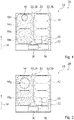
- the control unit 16 adapts a size of the virtual heating zones 18 to a size of the cooking utensil 14 that has been set up. For example, a first cooking utensil 14' is placed on precisely one heating element 12. In the operating mode, the control unit 16 defines four virtual heating zones 18a, 18b, 18c, 18d with different heating power densities, which are each formed by exactly one heating element 12 (cf. 1 ). The virtual heating zones 18a, 18b, 18c, 18d are formed by heating elements 12 arranged next to one another, the number and size of which are suitable for operating the cooking utensil 14'.
- Each of the virtual heating zones 18a, 18b, 18c, 18d has a different heating power density.
- the control unit 16 assigns a first heating power density to a first virtual heating zone 18a.
- the control unit 16 selects a virtual heating zone 18 facing an operator.
- the control unit selects a virtual heating zone facing away from an operator.
- the control unit selects a virtual heating zone which is covered by the cooking utensil that has been set up.
- the control unit 16 defines heating power densities of further virtual heating zones 18b, 18c, 18d, which differ from the first virtual heating zone 18a.
- the first heating power density of the first virtual heating zone 18a which is arranged in the area facing an operator when installed, is greater than the heating power densities of the other virtual heating zones 18b, 18c, 18d, which are formed by heating elements 12 of the same heating arrangement 26 as the first virtual heating zone 18a.
- the first heating power density of the first virtual heating zone 18a is greater than a second heating power density of a second virtual heating zone 18b, which is arranged adjacent to the first virtual heating zone 18a in the longitudinal direction 34 of the row.
- the second heating power density of the second virtual heating zone 18b is greater than a third heating power density of a third virtual heating zone 18c, which is arranged adjacent to the second virtual heating zone 18b in the longitudinal direction 34 of the row.
- the third heating power density of the third virtual heating zone 18c is greater than a fourth heating power density of a fourth virtual heating zone 18d, which is arranged adjacent to the third virtual heating zone 18d in the row longitudinal direction 34.
- the fourth heating power density of the fourth virtual heating zone 18d which is arranged in an area facing away from an operator when installed, is smaller than the heating power densities of the other virtual heating zones 18a, 18b, 18c, which are formed by heating elements 12 of the same heating arrangement 26 as the fourth virtual heating zone 18d.
- the control unit 16 operates a virtual heating zone 18 assigned to a set cooking utensil 14 depending on a position of the cooking utensil 14 with different heating power densities.
- the control unit 16 operates the virtual heating zones 18 in the longitudinal direction 34 of the row with different heating power densities.
- the control unit 16 operates a virtual heating zone 18a, 18e, 18h arranged in the installed state in an area facing an operator with a different heating power density than a virtual heating zone 18d, 18g, 18i arranged in the installed state in an area facing away from an operator.
- the control unit 16 includes a memory unit in which a heating power density is stored for each virtual heating zone 18 as a function of a position of the virtual heating zone 18 .
- the control unit 16 operates the virtual heating zones 18 as a function of position with predefined heating power densities that differ from one another.
- a predefined heating power density of a virtual heating zone 18a, 18e, 18h arranged in the installed state in the area facing an operator is greater than a predefined heating power density of a virtual heating zone 18d, 18g, 18i arranged in the installed state in the area facing away from an operator.
- control unit 16 assigns a higher heating power density to a virtual heating zone 18a, 18e, 18h, which is arranged in the area facing an operator, than to a virtual heating zone 18d, 18g, 18i, which is arranged in the area facing away from an operator.
- the control unit 16 changes an assignment of the predefined, differing heating power densities to the individual virtual heating zones 18.
- An operator input using the operator control unit 20 changes the control unit 16 when the operating mode is activated between a first sub-operating mode and a second sub-operational mode.
- a virtual heating zone 18a arranged in the area facing away from an operator when installed has a greater heating power density than a virtual heating zone 18d arranged in the area facing away from an operator when installed (cf. 1 ).
- a virtual heating zone 18a arranged in the area facing away from an operator when installed has a lower heating power density than a virtual heating zone 18d (not shown) arranged in the area facing away from an operator when installed.
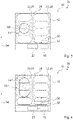
- a second cooking utensil 14" is set up, which covers two heating elements 12 arranged next to one another, then in the operating mode the control unit 16 defines three virtual heating zones 18e, 18f, 18g with different heat output densities, each of two arranged next to one another Heating elements 12 of one of the heating arrangements 26 are formed (cf. 2 and 3 ). Each of the virtual heating zones 18e, 18f, 18g has a different heating power density. In the operating mode, the control unit 16 assigns a first heating power density to a first virtual heating zone 18e.
- the first heating power density of the first virtual heating zone 18e which is arranged in the area facing an operator when installed, is greater than the heating power densities of the other virtual heating zones 18f, 18g, which are formed by heating elements 12 of the same heating arrangement 26 as the first virtual heating zone 18e.
- a second heating power density of the second virtual heating zone 18f is smaller than the first heating power density of the first virtual heating zone 18e and larger than a third heating power density of the third virtual heating zone 18g.
- the third heating power density of the third virtual heating zone 18g which is arranged in an area facing away from an operator when installed, is lower than the heating power densities of the other virtual heating zones 18e, 18f, which are formed by heating elements 12 of the same heating arrangement 26 as the third virtual heating zone 18g.
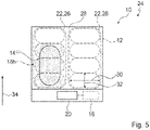
- the control unit 16 defines two virtual heating zones 18h, 18i with different heating power densities in the operating mode, which are each formed by two adjacent heating elements 12 of one of the heating arrangements 26 (cf. 4 and 5 ).
- the virtual heating zones 18h, 18i have different heating power densities.
- the control unit 16 assigns a first heating power density to a first virtual heating zone 18h.
- the first heating power density of the first virtual heating zone 18h which is arranged in the area facing an operator when installed, is greater than a second heating power density of a second virtual heating zone 18i, which is formed by heating elements 12 of the same heating arrangement 26 as the first virtual heating zone 18h .
- the second virtual heating zone 18i is arranged in an area facing away from an operator when installed.
- the control unit 16 changes a predefined heating power density of one of the virtual heating zones 18 stored in the memory unit as a function of an operator input using the operating unit 20.
- a predefined heating power density of a first virtual heating zone 18 changes, the control unit 16 changes depending on the change in the predefined heating power density of the first virtual heating zone 18 heating power densities of the other virtual heating zones 18, which are formed by heating elements 12 of the same heating arrangement 26 as the first virtual heating zone 18.
- the control unit 16 switches between the operating mode and two other operating modes depending on an operator input via the operator control unit 20 . In a first further operating mode, the control unit 16 operates the heating elements 12 with heating power densities that are independent of one another.
- the control unit 16 operates the heating elements 12 as a function of the position with predefined heating power densities that differ from one another. If a virtual heating zone 18 is formed by exactly one heating element 12, then the second additional operating mode is essentially the same as the operating mode. If a virtual heating zone 18 is formed by more than one heating element 12, then the second additional operating mode differs from the operating mode.
Landscapes
- Physics & Mathematics (AREA)
- Electromagnetism (AREA)
- Electric Stoves And Ranges (AREA)
- Cookers (AREA)
- Induction Heating Cooking Devices (AREA)
Claims (10)
- Dispositif pour table de cuisson avec au moins un agencement de chauffage (26) comportant au moins deux éléments chauffants (12), disposés l'un à côté de l'autre et servant au moins à chauffer des récipients de cuisson (14) déposés dessus et avec au moins une unité de commande (16),
dans lequel cette unité de commande (16) est prévue pour déterminer, dans un mode de fonctionnement en fonction de la dimension d'au moins un récipient de cuisson (14) déposé dessus, un nombre de zones de chauffe (18) virtuelles présentant une densité de puissance de chauffe différente, ces zones de chauffe (18) virtuelles étant formées d'éléments chauffants (12) disposés les uns à côté des autres, convenant de par leur nombre et/ou dimension à l'utilisation des récipients de cuisson (14) caractérisé en ce que le nombre de zones de chauffe (18) virtuelles diminue lorsque la dimension du récipient de cuisson (14) augmente. - Dispositif pour table de cuisson selon la revendication 1, caractérisé en ce que l'unité de commande (16) sert à attribuer, au moins dans un mode de fonctionnement, à une première zone de chauffe (18) virtuelle une première densité de puissance de chauffe, et à déterminer, en fonction de cette première densité de puissance de chauffe, des densités de puissance de chauffe d'autres zones de chauffe (18) virtuelles, autres que la première zone de chauffe (18) virtuelle.
- Dispositif pour table de cuisson selon l'une des revendications précédentes, caractérisé en ce que l'unité de commande (16) sert à faire fonctionner au moins dans un mode de fonctionnement, les zones de chauffe (18) virtuelles en fonction de leur position avec des densités de puissance de chauffe prédéfinies et différentes l'une de l'autre.
- Dispositif pour table de cuisson selon l'une des revendications précédentes, caractérisé en ce que l'unité de commande (16) sert à attribuer, au moins dans un mode de fonctionnement, à une zone de chauffe (18) virtuelle, disposée dans un espace tourné vers l'opérateur, une densité de puissance de chauffe supérieure à une zone de chauffe (18) virtuelle disposée dans un espace opposé à l'opérateur.
- Dispositif pour table de cuisson selon l'une des revendications précédentes, caractérisé en ce que l'unité de commande (16) sert à passer, en fonction d'une donnée d'opérateur au moyen d'au moins une unité de commande (20), du mode de fonctionnement à au moins un autre mode de fonctionnement.
- Dispositif pour table de cuisson selon l'une des revendications précédentes, caractérisé en ce que l'agencement de chauffe (26) comporte au moins trois éléments chauffants (12).
- Dispositif pour table de cuisson selon l'une des revendications précédentes, caractérisé en ce qu'au moins une partie des éléments chauffants (12) constitue une zone variable de plaque de cuisson (22).
- Dispositif pour table de cuisson selon les revendications 6 et 7, caractérisé en ce que les éléments chauffants (12) constituant la zone variable de plaque de cuisson (22) sont agencés en une rangée unique.
- Table de cuisson avec au moins un dispositif pour table de cuisson (10) selon l'une des revendications 1 à 8.
- Procédé de fonctionnement d'un dispositif pour table de cuisson (10) selon l'une des revendications 1 à 8, avec au moins un agencement de chauffe (26) comportant au moins deux éléments chauffants (12), lesquels sont disposés l'un à côté de l'autre et par lesquels les récipients de cuisson (14) déposés dessus sont chauffés, et avec au moins une unité de commande (16),
dans lequel au moins dans un mode de fonctionnement, par cette unité de commande (16), en fonction de la dimension d'au moins un récipient de cuisson (14) déposé dessus, un nombre de zones de chauffe (18) virtuelles présentant une densité de puissance de chauffe différente, est déterminé, ces zones de chauffe (18) virtuelles étant formées d'éléments chauffants (12) disposés les uns à côté des autres, convenant de par leur nombre et/ou dimension à l'utilisation des récipients de cuisson (14) caractérisé en que le nombre de zones de chauffe (18) virtuelles diminue lorsque la dimension du récipient de cuisson (14) augmente.
Applications Claiming Priority (2)
| Application Number | Priority Date | Filing Date | Title |
|---|---|---|---|
| ES201331187 | 2013-07-31 | ||
| PCT/IB2014/063204 WO2015015360A1 (fr) | 2013-07-31 | 2014-07-18 | Système de table de cuisson |
Publications (3)
| Publication Number | Publication Date |
|---|---|
| EP3028535A1 EP3028535A1 (fr) | 2016-06-08 |
| EP3028535B1 EP3028535B1 (fr) | 2019-09-11 |
| EP3028535B2 true EP3028535B2 (fr) | 2022-09-21 |
Family
ID=51541113
Family Applications (1)
| Application Number | Title | Priority Date | Filing Date |
|---|---|---|---|
| EP14766213.4A Active EP3028535B2 (fr) | 2013-07-31 | 2014-07-18 | Système de table de cuisson |
Country Status (3)
| Country | Link |
|---|---|
| US (1) | US10085304B2 (fr) |
| EP (1) | EP3028535B2 (fr) |
| WO (1) | WO2015015360A1 (fr) |
Families Citing this family (7)
| Publication number | Priority date | Publication date | Assignee | Title |
|---|---|---|---|---|
| EP2846607B1 (fr) | 2013-09-05 | 2016-05-18 | Electrolux Appliances Aktiebolag | Table de cuisson par induction comprenant une zone de cuisson avec trois ou plusieurs bobines d'induction et procédé permettant de commander une zone de cuisson |
| EP3116288B1 (fr) * | 2015-07-09 | 2020-05-13 | Electrolux Appliances Aktiebolag | Procédé pour commander une table de cuisson par induction comprenant un certain nombre de bobines d'induction |
| EP3282815B1 (fr) * | 2016-08-08 | 2019-05-15 | Electrolux Appliances Aktiebolag | Procédé de commande d'une plaque de cuisson à induction |
| DE102016217783A1 (de) | 2016-09-16 | 2018-03-22 | E.G.O. Elektro-Gerätebau GmbH | Verfahren zum Betrieb eines Kochfeldes mit mehreren Heizeinrichtungen |
| DE102018212094A1 (de) * | 2018-07-19 | 2020-01-23 | E.G.O. Elektro-Gerätebau GmbH | Heizeinrichtung für ein Kochfeld und Kochfeld |
| EP3767180A1 (fr) * | 2019-07-19 | 2021-01-20 | Electrolux Appliances Aktiebolag | Plaque de cuisson doté de zones de chauffage avec différentes températures |
| DE102021214821B3 (de) * | 2021-12-21 | 2023-03-30 | E.G.O. Elektro-Gerätebau GmbH | Verfahren zum Betrieb eines Kochfelds und Kochfeld |
Citations (24)
| Publication number | Priority date | Publication date | Assignee | Title |
|---|---|---|---|---|
| DE2932844A1 (de) † | 1979-08-14 | 1981-02-26 | Thielmann Ag Kg Geb | Einbau-kochfeld |
| EP0033082A1 (fr) † | 1980-01-25 | 1981-08-05 | NEFF-WERKE Carl Neff GmbH | Aire de cuisson encastrée |
| DE4007680A1 (de) † | 1990-03-10 | 1991-09-19 | Grass Ag | Heizplatte |
| WO1997037515A1 (fr) † | 1996-03-29 | 1997-10-09 | Kolja Kuse | Plaque chauffante homogene |
| US20070164017A1 (en) † | 2003-11-27 | 2007-07-19 | Brandt Industries | Method for heating a container placed on a cooktop by heating means associated to inductors |
| DE69836478T2 (de) † | 1998-07-10 | 2007-10-11 | Brandt Industries | Mehrzweck-Induktionskochherd |
| WO2008122495A1 (fr) † | 2007-04-09 | 2008-10-16 | BSH Bosch und Siemens Hausgeräte GmbH | Plan de cuisson et procédé d'utilisation d'un plan de cuisson |
| WO2009053279A1 (fr) † | 2007-10-25 | 2009-04-30 | BSH Bosch und Siemens Hausgeräte GmbH | Table de cuisson et procédé de fonctionnement d'un champ de cuisson |
| WO2009090152A1 (fr) † | 2008-01-14 | 2009-07-23 | BSH Bosch und Siemens Hausgeräte GmbH | Plaque de cuisson à induction munie d'une pluralité d'éléments chauffants à induction |
| WO2010069883A1 (fr) † | 2008-12-19 | 2010-06-24 | BSH Bosch und Siemens Hausgeräte GmbH | Plaque de cuisson à induction et procédé d'utilisation d'une plaque de cuisson à induction |
| WO2010084096A2 (fr) † | 2009-01-20 | 2010-07-29 | BSH Bosch und Siemens Hausgeräte GmbH | Plaque de cuisson comportant au moins une zone de chauffe composée de plusieurs éléments de chauffe |
| WO2010118943A1 (fr) † | 2009-04-17 | 2010-10-21 | BSH Bosch und Siemens Hausgeräte GmbH | Plaque de cuisson équipée d'un ensemble de détection et procédé de fonctionnement d'une plaque de cuisson |
| EP2265087A2 (fr) † | 2004-06-25 | 2010-12-22 | Fagorbrandt Sas | Table de cuisson à plusieurs foyers de cuisson indèpendants |
| WO2011107325A1 (fr) † | 2010-03-03 | 2011-09-09 | BSH Bosch und Siemens Hausgeräte GmbH | Table de cuisson comportant au moins une zone de cuisson, ainsi que procédé de fonctionnement d'une table de cuisson |
| EP2551600A1 (fr) † | 2011-07-26 | 2013-01-30 | FagorBrandt SAS | Table de cuisson et procédé de commande en fonctionnement d'une table de cuisson |
| EP2600067A1 (fr) † | 2011-11-30 | 2013-06-05 | BSH Bosch und Siemens Hausgeräte GmbH | Procédé destiné au fonctionnement d'un champ de cuisson ainsi que champ de cuisson |
| EP2600065A2 (fr) † | 2011-11-30 | 2013-06-05 | BSH Bosch und Siemens Hausgeräte GmbH | Procédé destiné au fonctionnement d'un plan de cuisson ainsi que plan de cuisson |
| FR2984463A1 (fr) † | 2011-12-16 | 2013-06-21 | Fagorbrandt Sas | Table de cuisson comprenant au moins deux parties de cuisson d'un plan de cuisson |
| EP2670211A2 (fr) † | 2012-05-31 | 2013-12-04 | BSH Bosch und Siemens Hausgeräte GmbH | Dispositif de champ de cuisson |
| EP2688365A1 (fr) † | 2012-07-20 | 2014-01-22 | BSH Bosch und Siemens Hausgeräte GmbH | Dispositif de plaque de cuisson |
| EP2688364A1 (fr) † | 2012-07-20 | 2014-01-22 | BSH Bosch und Siemens Hausgeräte GmbH | Dispositif de champ de cuisson |
| EP2688366A1 (fr) † | 2012-07-20 | 2014-01-22 | BSH Bosch und Siemens Hausgeräte GmbH | Dispositif de champ de cuisson |
| EP2703728A1 (fr) † | 2012-09-03 | 2014-03-05 | BSH Bosch und Siemens Hausgeräte GmbH | Dispositif de plate de cuisson |
| EP2709424A1 (fr) † | 2012-09-17 | 2014-03-19 | Electrolux Professional S.p.A. | Plaque de cuisson à induction améliorée |
Family Cites Families (4)
| Publication number | Priority date | Publication date | Assignee | Title |
|---|---|---|---|---|
| US3953711A (en) | 1973-11-06 | 1976-04-27 | E.G.O. Elektro-Geraete Blanc Und Fischer | Cooking units |
| ES2324449B1 (es) | 2007-07-31 | 2010-05-25 | Bsh Electrodomesticos España, S.A | Campo de coccion con una pluralidad de elementos de calentamiento y procedimiento para el accionamiento de un campo de coccion. |
| ES2362839B1 (es) * | 2009-04-17 | 2012-05-22 | Bsh Electrodomesticos España, S.A. | Procedimiento para detectar elementos de bater�?a de cocción sobre un campo de cocción de matriz. |
| KR101844405B1 (ko) * | 2011-04-08 | 2018-04-03 | 삼성전자주식회사 | 유도가열조리기 및 그 제어방법 |
-
2014
- 2014-07-18 EP EP14766213.4A patent/EP3028535B2/fr active Active
- 2014-07-18 US US14/904,705 patent/US10085304B2/en active Active
- 2014-07-18 WO PCT/IB2014/063204 patent/WO2015015360A1/fr active Application Filing
Patent Citations (24)
| Publication number | Priority date | Publication date | Assignee | Title |
|---|---|---|---|---|
| DE2932844A1 (de) † | 1979-08-14 | 1981-02-26 | Thielmann Ag Kg Geb | Einbau-kochfeld |
| EP0033082A1 (fr) † | 1980-01-25 | 1981-08-05 | NEFF-WERKE Carl Neff GmbH | Aire de cuisson encastrée |
| DE4007680A1 (de) † | 1990-03-10 | 1991-09-19 | Grass Ag | Heizplatte |
| WO1997037515A1 (fr) † | 1996-03-29 | 1997-10-09 | Kolja Kuse | Plaque chauffante homogene |
| DE69836478T2 (de) † | 1998-07-10 | 2007-10-11 | Brandt Industries | Mehrzweck-Induktionskochherd |
| US20070164017A1 (en) † | 2003-11-27 | 2007-07-19 | Brandt Industries | Method for heating a container placed on a cooktop by heating means associated to inductors |
| EP2265087A2 (fr) † | 2004-06-25 | 2010-12-22 | Fagorbrandt Sas | Table de cuisson à plusieurs foyers de cuisson indèpendants |
| WO2008122495A1 (fr) † | 2007-04-09 | 2008-10-16 | BSH Bosch und Siemens Hausgeräte GmbH | Plan de cuisson et procédé d'utilisation d'un plan de cuisson |
| WO2009053279A1 (fr) † | 2007-10-25 | 2009-04-30 | BSH Bosch und Siemens Hausgeräte GmbH | Table de cuisson et procédé de fonctionnement d'un champ de cuisson |
| WO2009090152A1 (fr) † | 2008-01-14 | 2009-07-23 | BSH Bosch und Siemens Hausgeräte GmbH | Plaque de cuisson à induction munie d'une pluralité d'éléments chauffants à induction |
| WO2010069883A1 (fr) † | 2008-12-19 | 2010-06-24 | BSH Bosch und Siemens Hausgeräte GmbH | Plaque de cuisson à induction et procédé d'utilisation d'une plaque de cuisson à induction |
| WO2010084096A2 (fr) † | 2009-01-20 | 2010-07-29 | BSH Bosch und Siemens Hausgeräte GmbH | Plaque de cuisson comportant au moins une zone de chauffe composée de plusieurs éléments de chauffe |
| WO2010118943A1 (fr) † | 2009-04-17 | 2010-10-21 | BSH Bosch und Siemens Hausgeräte GmbH | Plaque de cuisson équipée d'un ensemble de détection et procédé de fonctionnement d'une plaque de cuisson |
| WO2011107325A1 (fr) † | 2010-03-03 | 2011-09-09 | BSH Bosch und Siemens Hausgeräte GmbH | Table de cuisson comportant au moins une zone de cuisson, ainsi que procédé de fonctionnement d'une table de cuisson |
| EP2551600A1 (fr) † | 2011-07-26 | 2013-01-30 | FagorBrandt SAS | Table de cuisson et procédé de commande en fonctionnement d'une table de cuisson |
| EP2600065A2 (fr) † | 2011-11-30 | 2013-06-05 | BSH Bosch und Siemens Hausgeräte GmbH | Procédé destiné au fonctionnement d'un plan de cuisson ainsi que plan de cuisson |
| EP2600067A1 (fr) † | 2011-11-30 | 2013-06-05 | BSH Bosch und Siemens Hausgeräte GmbH | Procédé destiné au fonctionnement d'un champ de cuisson ainsi que champ de cuisson |
| FR2984463A1 (fr) † | 2011-12-16 | 2013-06-21 | Fagorbrandt Sas | Table de cuisson comprenant au moins deux parties de cuisson d'un plan de cuisson |
| EP2670211A2 (fr) † | 2012-05-31 | 2013-12-04 | BSH Bosch und Siemens Hausgeräte GmbH | Dispositif de champ de cuisson |
| EP2688365A1 (fr) † | 2012-07-20 | 2014-01-22 | BSH Bosch und Siemens Hausgeräte GmbH | Dispositif de plaque de cuisson |
| EP2688364A1 (fr) † | 2012-07-20 | 2014-01-22 | BSH Bosch und Siemens Hausgeräte GmbH | Dispositif de champ de cuisson |
| EP2688366A1 (fr) † | 2012-07-20 | 2014-01-22 | BSH Bosch und Siemens Hausgeräte GmbH | Dispositif de champ de cuisson |
| EP2703728A1 (fr) † | 2012-09-03 | 2014-03-05 | BSH Bosch und Siemens Hausgeräte GmbH | Dispositif de plate de cuisson |
| EP2709424A1 (fr) † | 2012-09-17 | 2014-03-19 | Electrolux Professional S.p.A. | Plaque de cuisson à induction améliorée |
Also Published As
| Publication number | Publication date |
|---|---|
| US10085304B2 (en) | 2018-09-25 |
| EP3028535A1 (fr) | 2016-06-08 |
| US20160157301A1 (en) | 2016-06-02 |
| EP3028535B1 (fr) | 2019-09-11 |
| WO2015015360A1 (fr) | 2015-02-05 |
Similar Documents
| Publication | Publication Date | Title |
|---|---|---|
| EP3028535B2 (fr) | Système de table de cuisson | |
| EP2833697B1 (fr) | Dispositif de plaque de cuisson | |
| EP3028536B1 (fr) | Système de table de cuisson | |
| DE102014105161B4 (de) | Verfahren zum Betreiben einer Kochfeldeinrichtung und Kochfeldeinrichtung | |
| EP2688366B1 (fr) | Dispositif de champ de cuisson | |
| EP2840867B1 (fr) | Dispositif de plaque de cuisson | |
| EP3001772B1 (fr) | Plaque de cuisson | |
| EP2688364B1 (fr) | Dispositif de champ de cuisson | |
| WO2005069688A2 (fr) | Procede de commande pour elements chauffants, dispositif, et plaque de cuisson | |
| EP2670211A2 (fr) | Dispositif de champ de cuisson | |
| EP2704523B1 (fr) | Dispositif de champ de cuisson à induction | |
| EP3028540B1 (fr) | Ensemble table de cuisson | |
| DE102013218715A1 (de) | Kochfeldvorrichtung | |
| EP3028538B1 (fr) | Système de table de cuisson | |
| EP3081051B1 (fr) | Table de cuisson | |
| EP3028539B1 (fr) | Système de table de cuisson | |
| EP3028537B1 (fr) | Système de table de cuisson | |
| EP3484242B1 (fr) | Dispositif formant appareil de cuisson inductif | |
| EP3136822A1 (fr) | Procede de determination de temperature | |
| WO2019092528A1 (fr) | Système de table de cuisson | |
| EP2552176A2 (fr) | Dispositif de champ de cuisson | |
| WO2023099659A1 (fr) | Dispositif de plaque de cuisson, plaque de cuisson et procédé de fonctionnement d'un dispositif de plaque de cuisson | |
| EP3565379A1 (fr) | Dispositif d'induction | |
| EP3509392B1 (fr) | Procédé pour une plaque de cuisson | |
| EP2741572B1 (fr) | Dispositif de plaque de cuisson |
Legal Events
| Date | Code | Title | Description |
|---|---|---|---|
| PUAI | Public reference made under article 153(3) epc to a published international application that has entered the european phase |
Free format text: ORIGINAL CODE: 0009012 |
|
| 17P | Request for examination filed |
Effective date: 20160229 |
|
| AK | Designated contracting states |
Kind code of ref document: A1 Designated state(s): AL AT BE BG CH CY CZ DE DK EE ES FI FR GB GR HR HU IE IS IT LI LT LU LV MC MK MT NL NO PL PT RO RS SE SI SK SM TR |
|
| AX | Request for extension of the european patent |
Extension state: BA ME |
|
| DAX | Request for extension of the european patent (deleted) | ||
| GRAP | Despatch of communication of intention to grant a patent |
Free format text: ORIGINAL CODE: EPIDOSNIGR1 |
|
| STAA | Information on the status of an ep patent application or granted ep patent |
Free format text: STATUS: GRANT OF PATENT IS INTENDED |
|
| INTG | Intention to grant announced |
Effective date: 20190417 |
|
| GRAS | Grant fee paid |
Free format text: ORIGINAL CODE: EPIDOSNIGR3 |
|
| GRAA | (expected) grant |
Free format text: ORIGINAL CODE: 0009210 |
|
| STAA | Information on the status of an ep patent application or granted ep patent |
Free format text: STATUS: THE PATENT HAS BEEN GRANTED |
|
| AK | Designated contracting states |
Kind code of ref document: B1 Designated state(s): AL AT BE BG CH CY CZ DE DK EE ES FI FR GB GR HR HU IE IS IT LI LT LU LV MC MK MT NL NO PL PT RO RS SE SI SK SM TR |
|
| REG | Reference to a national code |
Ref country code: GB Ref legal event code: FG4D Free format text: NOT ENGLISH |
|
| REG | Reference to a national code |
Ref country code: CH Ref legal event code: EP |
|
| REG | Reference to a national code |
Ref country code: AT Ref legal event code: REF Ref document number: 1180162 Country of ref document: AT Kind code of ref document: T Effective date: 20190915 |
|
| REG | Reference to a national code |
Ref country code: DE Ref legal event code: R096 Ref document number: 502014012640 Country of ref document: DE Ref country code: IE Ref legal event code: FG4D Free format text: LANGUAGE OF EP DOCUMENT: GERMAN |
|
| REG | Reference to a national code |
Ref country code: NL Ref legal event code: MP Effective date: 20190911 |
|
| REG | Reference to a national code |
Ref country code: LT Ref legal event code: MG4D |
|
| PG25 | Lapsed in a contracting state [announced via postgrant information from national office to epo] |
Ref country code: FI Free format text: LAPSE BECAUSE OF FAILURE TO SUBMIT A TRANSLATION OF THE DESCRIPTION OR TO PAY THE FEE WITHIN THE PRESCRIBED TIME-LIMIT Effective date: 20190911 Ref country code: LT Free format text: LAPSE BECAUSE OF FAILURE TO SUBMIT A TRANSLATION OF THE DESCRIPTION OR TO PAY THE FEE WITHIN THE PRESCRIBED TIME-LIMIT Effective date: 20190911 Ref country code: HR Free format text: LAPSE BECAUSE OF FAILURE TO SUBMIT A TRANSLATION OF THE DESCRIPTION OR TO PAY THE FEE WITHIN THE PRESCRIBED TIME-LIMIT Effective date: 20190911 Ref country code: BG Free format text: LAPSE BECAUSE OF FAILURE TO SUBMIT A TRANSLATION OF THE DESCRIPTION OR TO PAY THE FEE WITHIN THE PRESCRIBED TIME-LIMIT Effective date: 20191211 Ref country code: NO Free format text: LAPSE BECAUSE OF FAILURE TO SUBMIT A TRANSLATION OF THE DESCRIPTION OR TO PAY THE FEE WITHIN THE PRESCRIBED TIME-LIMIT Effective date: 20191211 Ref country code: SE Free format text: LAPSE BECAUSE OF FAILURE TO SUBMIT A TRANSLATION OF THE DESCRIPTION OR TO PAY THE FEE WITHIN THE PRESCRIBED TIME-LIMIT Effective date: 20190911 |
|
| PG25 | Lapsed in a contracting state [announced via postgrant information from national office to epo] |
Ref country code: ES Free format text: LAPSE BECAUSE OF FAILURE TO SUBMIT A TRANSLATION OF THE DESCRIPTION OR TO PAY THE FEE WITHIN THE PRESCRIBED TIME-LIMIT Effective date: 20190911 Ref country code: GR Free format text: LAPSE BECAUSE OF FAILURE TO SUBMIT A TRANSLATION OF THE DESCRIPTION OR TO PAY THE FEE WITHIN THE PRESCRIBED TIME-LIMIT Effective date: 20191212 Ref country code: LV Free format text: LAPSE BECAUSE OF FAILURE TO SUBMIT A TRANSLATION OF THE DESCRIPTION OR TO PAY THE FEE WITHIN THE PRESCRIBED TIME-LIMIT Effective date: 20190911 Ref country code: AL Free format text: LAPSE BECAUSE OF FAILURE TO SUBMIT A TRANSLATION OF THE DESCRIPTION OR TO PAY THE FEE WITHIN THE PRESCRIBED TIME-LIMIT Effective date: 20190911 Ref country code: RS Free format text: LAPSE BECAUSE OF FAILURE TO SUBMIT A TRANSLATION OF THE DESCRIPTION OR TO PAY THE FEE WITHIN THE PRESCRIBED TIME-LIMIT Effective date: 20190911 |
|
| PG25 | Lapsed in a contracting state [announced via postgrant information from national office to epo] |
Ref country code: PL Free format text: LAPSE BECAUSE OF FAILURE TO SUBMIT A TRANSLATION OF THE DESCRIPTION OR TO PAY THE FEE WITHIN THE PRESCRIBED TIME-LIMIT Effective date: 20190911 Ref country code: EE Free format text: LAPSE BECAUSE OF FAILURE TO SUBMIT A TRANSLATION OF THE DESCRIPTION OR TO PAY THE FEE WITHIN THE PRESCRIBED TIME-LIMIT Effective date: 20190911 Ref country code: IT Free format text: LAPSE BECAUSE OF FAILURE TO SUBMIT A TRANSLATION OF THE DESCRIPTION OR TO PAY THE FEE WITHIN THE PRESCRIBED TIME-LIMIT Effective date: 20190911 Ref country code: NL Free format text: LAPSE BECAUSE OF FAILURE TO SUBMIT A TRANSLATION OF THE DESCRIPTION OR TO PAY THE FEE WITHIN THE PRESCRIBED TIME-LIMIT Effective date: 20190911 Ref country code: RO Free format text: LAPSE BECAUSE OF FAILURE TO SUBMIT A TRANSLATION OF THE DESCRIPTION OR TO PAY THE FEE WITHIN THE PRESCRIBED TIME-LIMIT Effective date: 20190911 Ref country code: PT Free format text: LAPSE BECAUSE OF FAILURE TO SUBMIT A TRANSLATION OF THE DESCRIPTION OR TO PAY THE FEE WITHIN THE PRESCRIBED TIME-LIMIT Effective date: 20200113 |
|
| PG25 | Lapsed in a contracting state [announced via postgrant information from national office to epo] |
Ref country code: SK Free format text: LAPSE BECAUSE OF FAILURE TO SUBMIT A TRANSLATION OF THE DESCRIPTION OR TO PAY THE FEE WITHIN THE PRESCRIBED TIME-LIMIT Effective date: 20190911 Ref country code: IS Free format text: LAPSE BECAUSE OF FAILURE TO SUBMIT A TRANSLATION OF THE DESCRIPTION OR TO PAY THE FEE WITHIN THE PRESCRIBED TIME-LIMIT Effective date: 20200224 Ref country code: SM Free format text: LAPSE BECAUSE OF FAILURE TO SUBMIT A TRANSLATION OF THE DESCRIPTION OR TO PAY THE FEE WITHIN THE PRESCRIBED TIME-LIMIT Effective date: 20190911 Ref country code: CZ Free format text: LAPSE BECAUSE OF FAILURE TO SUBMIT A TRANSLATION OF THE DESCRIPTION OR TO PAY THE FEE WITHIN THE PRESCRIBED TIME-LIMIT Effective date: 20190911 |
|
| REG | Reference to a national code |
Ref country code: DE Ref legal event code: R026 Ref document number: 502014012640 Country of ref document: DE |
|
| PLBI | Opposition filed |
Free format text: ORIGINAL CODE: 0009260 |
|
| PLAX | Notice of opposition and request to file observation + time limit sent |
Free format text: ORIGINAL CODE: EPIDOSNOBS2 |
|
| 26 | Opposition filed |
Opponent name: ELECTROLUX ROTHENBURG GMBH FACTORY AND DEVELOPMENT Effective date: 20200605 |
|
| PG2D | Information on lapse in contracting state deleted |
Ref country code: IS |
|
| PG25 | Lapsed in a contracting state [announced via postgrant information from national office to epo] |
Ref country code: DK Free format text: LAPSE BECAUSE OF FAILURE TO SUBMIT A TRANSLATION OF THE DESCRIPTION OR TO PAY THE FEE WITHIN THE PRESCRIBED TIME-LIMIT Effective date: 20190911 Ref country code: IS Free format text: LAPSE BECAUSE OF FAILURE TO SUBMIT A TRANSLATION OF THE DESCRIPTION OR TO PAY THE FEE WITHIN THE PRESCRIBED TIME-LIMIT Effective date: 20200112 |
|
| PG25 | Lapsed in a contracting state [announced via postgrant information from national office to epo] |
Ref country code: SI Free format text: LAPSE BECAUSE OF FAILURE TO SUBMIT A TRANSLATION OF THE DESCRIPTION OR TO PAY THE FEE WITHIN THE PRESCRIBED TIME-LIMIT Effective date: 20190911 |
|
| PLBB | Reply of patent proprietor to notice(s) of opposition received |
Free format text: ORIGINAL CODE: EPIDOSNOBS3 |
|
| PG25 | Lapsed in a contracting state [announced via postgrant information from national office to epo] |
Ref country code: MC Free format text: LAPSE BECAUSE OF FAILURE TO SUBMIT A TRANSLATION OF THE DESCRIPTION OR TO PAY THE FEE WITHIN THE PRESCRIBED TIME-LIMIT Effective date: 20190911 |
|
| REG | Reference to a national code |
Ref country code: CH Ref legal event code: PL |
|
| GBPC | Gb: european patent ceased through non-payment of renewal fee |
Effective date: 20200718 |
|
| REG | Reference to a national code |
Ref country code: BE Ref legal event code: MM Effective date: 20200731 |
|
| PG25 | Lapsed in a contracting state [announced via postgrant information from national office to epo] |
Ref country code: CH Free format text: LAPSE BECAUSE OF NON-PAYMENT OF DUE FEES Effective date: 20200731 Ref country code: LI Free format text: LAPSE BECAUSE OF NON-PAYMENT OF DUE FEES Effective date: 20200731 Ref country code: GB Free format text: LAPSE BECAUSE OF NON-PAYMENT OF DUE FEES Effective date: 20200718 Ref country code: LU Free format text: LAPSE BECAUSE OF NON-PAYMENT OF DUE FEES Effective date: 20200718 Ref country code: FR Free format text: LAPSE BECAUSE OF NON-PAYMENT OF DUE FEES Effective date: 20200731 |
|
| PG25 | Lapsed in a contracting state [announced via postgrant information from national office to epo] |
Ref country code: BE Free format text: LAPSE BECAUSE OF NON-PAYMENT OF DUE FEES Effective date: 20200731 |
|
| PG25 | Lapsed in a contracting state [announced via postgrant information from national office to epo] |
Ref country code: IE Free format text: LAPSE BECAUSE OF NON-PAYMENT OF DUE FEES Effective date: 20200718 |
|
| REG | Reference to a national code |
Ref country code: AT Ref legal event code: MM01 Ref document number: 1180162 Country of ref document: AT Kind code of ref document: T Effective date: 20200718 |
|
| PG25 | Lapsed in a contracting state [announced via postgrant information from national office to epo] |
Ref country code: AT Free format text: LAPSE BECAUSE OF NON-PAYMENT OF DUE FEES Effective date: 20200718 |
|
| PG25 | Lapsed in a contracting state [announced via postgrant information from national office to epo] |
Ref country code: TR Free format text: LAPSE BECAUSE OF FAILURE TO SUBMIT A TRANSLATION OF THE DESCRIPTION OR TO PAY THE FEE WITHIN THE PRESCRIBED TIME-LIMIT Effective date: 20190911 Ref country code: MT Free format text: LAPSE BECAUSE OF FAILURE TO SUBMIT A TRANSLATION OF THE DESCRIPTION OR TO PAY THE FEE WITHIN THE PRESCRIBED TIME-LIMIT Effective date: 20190911 Ref country code: CY Free format text: LAPSE BECAUSE OF FAILURE TO SUBMIT A TRANSLATION OF THE DESCRIPTION OR TO PAY THE FEE WITHIN THE PRESCRIBED TIME-LIMIT Effective date: 20190911 |
|
| PG25 | Lapsed in a contracting state [announced via postgrant information from national office to epo] |
Ref country code: MK Free format text: LAPSE BECAUSE OF FAILURE TO SUBMIT A TRANSLATION OF THE DESCRIPTION OR TO PAY THE FEE WITHIN THE PRESCRIBED TIME-LIMIT Effective date: 20190911 |
|
| PUAH | Patent maintained in amended form |
Free format text: ORIGINAL CODE: 0009272 |
|
| STAA | Information on the status of an ep patent application or granted ep patent |
Free format text: STATUS: PATENT MAINTAINED AS AMENDED |
|
| 27A | Patent maintained in amended form |
Effective date: 20220921 |
|
| AK | Designated contracting states |
Kind code of ref document: B2 Designated state(s): AL AT BE BG CH CY CZ DE DK EE ES FI FR GB GR HR HU IE IS IT LI LT LU LV MC MK MT NL NO PL PT RO RS SE SI SK SM TR |
|
| REG | Reference to a national code |
Ref country code: DE Ref legal event code: R102 Ref document number: 502014012640 Country of ref document: DE |
|
| PGFP | Annual fee paid to national office [announced via postgrant information from national office to epo] |
Ref country code: DE Payment date: 20230731 Year of fee payment: 10 |