EP3027319B1 - Fluidpatrone und verfahren zur verarbeitung einer flüssigen probe - Google Patents
Fluidpatrone und verfahren zur verarbeitung einer flüssigen probe Download PDFInfo
- Publication number
- EP3027319B1 EP3027319B1 EP14744943.3A EP14744943A EP3027319B1 EP 3027319 B1 EP3027319 B1 EP 3027319B1 EP 14744943 A EP14744943 A EP 14744943A EP 3027319 B1 EP3027319 B1 EP 3027319B1
- Authority
- EP
- European Patent Office
- Prior art keywords
- channel
- branch
- liquid
- gas
- valve
- Prior art date
- Legal status (The legal status is an assumption and is not a legal conclusion. Google has not performed a legal analysis and makes no representation as to the accuracy of the status listed.)
- Active
Links
- 239000007788 liquid Substances 0.000 title claims description 359
- 238000000034 method Methods 0.000 title claims description 46
- 238000012545 processing Methods 0.000 title claims description 18
- 238000011144 upstream manufacturing Methods 0.000 claims description 43
- 238000010926 purge Methods 0.000 claims description 5
- 230000001419 dependent effect Effects 0.000 claims description 4
- 239000000523 sample Substances 0.000 description 315
- 150000007523 nucleic acids Chemical class 0.000 description 133
- 108020004707 nucleic acids Proteins 0.000 description 129
- 102000039446 nucleic acids Human genes 0.000 description 129
- 239000010410 layer Substances 0.000 description 117
- 238000003199 nucleic acid amplification method Methods 0.000 description 115
- 230000003321 amplification Effects 0.000 description 104
- 239000012530 fluid Substances 0.000 description 93
- 238000001514 detection method Methods 0.000 description 87
- 239000003153 chemical reaction reagent Substances 0.000 description 73
- 239000011888 foil Substances 0.000 description 67
- 239000002699 waste material Substances 0.000 description 61
- 239000012528 membrane Substances 0.000 description 56
- 238000012360 testing method Methods 0.000 description 51
- 238000002156 mixing Methods 0.000 description 48
- 239000012149 elution buffer Substances 0.000 description 44
- 239000011534 wash buffer Substances 0.000 description 44
- 238000002955 isolation Methods 0.000 description 31
- 238000010828 elution Methods 0.000 description 19
- 230000008859 change Effects 0.000 description 18
- -1 resinoids Polymers 0.000 description 18
- 229920003023 plastic Polymers 0.000 description 17
- 239000004033 plastic Substances 0.000 description 17
- 238000004458 analytical method Methods 0.000 description 15
- 238000011109 contamination Methods 0.000 description 15
- 238000003752 polymerase chain reaction Methods 0.000 description 15
- 239000012139 lysis buffer Substances 0.000 description 13
- 239000000463 material Substances 0.000 description 12
- 239000013641 positive control Substances 0.000 description 12
- 238000006243 chemical reaction Methods 0.000 description 11
- 238000003780 insertion Methods 0.000 description 11
- 230000037431 insertion Effects 0.000 description 11
- 238000004519 manufacturing process Methods 0.000 description 11
- 239000004743 Polypropylene Substances 0.000 description 10
- 239000000872 buffer Substances 0.000 description 10
- 229920001155 polypropylene Polymers 0.000 description 10
- 230000007062 hydrolysis Effects 0.000 description 9
- 238000006460 hydrolysis reaction Methods 0.000 description 9
- 230000037361 pathway Effects 0.000 description 9
- 230000001413 cellular effect Effects 0.000 description 8
- 238000012864 cross contamination Methods 0.000 description 8
- 238000010586 diagram Methods 0.000 description 8
- 229920000642 polymer Polymers 0.000 description 8
- 101710163270 Nuclease Proteins 0.000 description 7
- 238000013461 design Methods 0.000 description 7
- 230000000007 visual effect Effects 0.000 description 7
- 238000003556 assay Methods 0.000 description 6
- 230000006037 cell lysis Effects 0.000 description 6
- 238000004140 cleaning Methods 0.000 description 6
- 229920000139 polyethylene terephthalate Polymers 0.000 description 6
- 239000005020 polyethylene terephthalate Substances 0.000 description 6
- 239000000758 substrate Substances 0.000 description 6
- 241001465754 Metazoa Species 0.000 description 5
- 239000002250 absorbent Substances 0.000 description 5
- 230000002745 absorbent Effects 0.000 description 5
- 230000009471 action Effects 0.000 description 5
- 239000002131 composite material Substances 0.000 description 5
- 239000000243 solution Substances 0.000 description 5
- 241000894006 Bacteria Species 0.000 description 4
- 241000606153 Chlamydia trachomatis Species 0.000 description 4
- 108020004414 DNA Proteins 0.000 description 4
- 238000012408 PCR amplification Methods 0.000 description 4
- 238000000429 assembly Methods 0.000 description 4
- 230000009286 beneficial effect Effects 0.000 description 4
- 230000009089 cytolysis Effects 0.000 description 4
- 230000000694 effects Effects 0.000 description 4
- KTWOOEGAPBSYNW-UHFFFAOYSA-N ferrocene Chemical compound [Fe+2].C=1C=C[CH-]C=1.C=1C=C[CH-]C=1 KTWOOEGAPBSYNW-UHFFFAOYSA-N 0.000 description 4
- 238000009396 hybridization Methods 0.000 description 4
- 239000000203 mixture Substances 0.000 description 4
- 239000002773 nucleotide Substances 0.000 description 4
- 244000052769 pathogen Species 0.000 description 4
- 230000001717 pathogenic effect Effects 0.000 description 4
- 238000002360 preparation method Methods 0.000 description 4
- 239000007787 solid Substances 0.000 description 4
- 102000004533 Endonucleases Human genes 0.000 description 3
- 108010042407 Endonucleases Proteins 0.000 description 3
- 108091028043 Nucleic acid sequence Proteins 0.000 description 3
- 241000251539 Vertebrata <Metazoa> Species 0.000 description 3
- 230000000712 assembly Effects 0.000 description 3
- 239000012298 atmosphere Substances 0.000 description 3
- 230000008901 benefit Effects 0.000 description 3
- 150000001875 compounds Chemical class 0.000 description 3
- 238000009826 distribution Methods 0.000 description 3
- 239000003792 electrolyte Substances 0.000 description 3
- 238000005516 engineering process Methods 0.000 description 3
- 238000005304 joining Methods 0.000 description 3
- 229910052751 metal Inorganic materials 0.000 description 3
- 239000002184 metal Substances 0.000 description 3
- 239000013642 negative control Substances 0.000 description 3
- 125000003729 nucleotide group Chemical group 0.000 description 3
- 238000000926 separation method Methods 0.000 description 3
- 238000001356 surgical procedure Methods 0.000 description 3
- 231100000331 toxic Toxicity 0.000 description 3
- 230000002588 toxic effect Effects 0.000 description 3
- 238000012546 transfer Methods 0.000 description 3
- 210000002700 urine Anatomy 0.000 description 3
- 108010014303 DNA-directed DNA polymerase Proteins 0.000 description 2
- 102000016928 DNA-directed DNA polymerase Human genes 0.000 description 2
- TWRXJAOTZQYOKJ-UHFFFAOYSA-L Magnesium chloride Chemical compound [Mg+2].[Cl-].[Cl-] TWRXJAOTZQYOKJ-UHFFFAOYSA-L 0.000 description 2
- 241000124008 Mammalia Species 0.000 description 2
- 238000002944 PCR assay Methods 0.000 description 2
- 241001148142 Pectobacterium atrosepticum Species 0.000 description 2
- 241000288906 Primates Species 0.000 description 2
- VYPSYNLAJGMNEJ-UHFFFAOYSA-N Silicium dioxide Chemical compound O=[Si]=O VYPSYNLAJGMNEJ-UHFFFAOYSA-N 0.000 description 2
- BQCADISMDOOEFD-UHFFFAOYSA-N Silver Chemical compound [Ag] BQCADISMDOOEFD-UHFFFAOYSA-N 0.000 description 2
- 108010006785 Taq Polymerase Proteins 0.000 description 2
- 238000009825 accumulation Methods 0.000 description 2
- XECAHXYUAAWDEL-UHFFFAOYSA-N acrylonitrile butadiene styrene Chemical compound C=CC=C.C=CC#N.C=CC1=CC=CC=C1 XECAHXYUAAWDEL-UHFFFAOYSA-N 0.000 description 2
- 239000004676 acrylonitrile butadiene styrene Substances 0.000 description 2
- 229920000122 acrylonitrile butadiene styrene Polymers 0.000 description 2
- 239000000443 aerosol Substances 0.000 description 2
- 238000013459 approach Methods 0.000 description 2
- 239000008280 blood Substances 0.000 description 2
- 210000004369 blood Anatomy 0.000 description 2
- 210000001124 body fluid Anatomy 0.000 description 2
- 229940038705 chlamydia trachomatis Drugs 0.000 description 2
- 238000003759 clinical diagnosis Methods 0.000 description 2
- 238000004891 communication Methods 0.000 description 2
- 230000001276 controlling effect Effects 0.000 description 2
- 239000003599 detergent Substances 0.000 description 2
- 238000003745 diagnosis Methods 0.000 description 2
- 230000005518 electrochemistry Effects 0.000 description 2
- 238000011010 flushing procedure Methods 0.000 description 2
- 239000003365 glass fiber Substances 0.000 description 2
- ZJYYHGLJYGJLLN-UHFFFAOYSA-N guanidinium thiocyanate Chemical compound SC#N.NC(N)=N ZJYYHGLJYGJLLN-UHFFFAOYSA-N 0.000 description 2
- 238000010438 heat treatment Methods 0.000 description 2
- 238000007834 ligase chain reaction Methods 0.000 description 2
- 239000013047 polymeric layer Substances 0.000 description 2
- 230000008569 process Effects 0.000 description 2
- 235000018102 proteins Nutrition 0.000 description 2
- 102000004169 proteins and genes Human genes 0.000 description 2
- 108090000623 proteins and genes Proteins 0.000 description 2
- 210000003296 saliva Anatomy 0.000 description 2
- 239000012723 sample buffer Substances 0.000 description 2
- 238000007789 sealing Methods 0.000 description 2
- 230000035945 sensitivity Effects 0.000 description 2
- 229910052709 silver Inorganic materials 0.000 description 2
- 239000004332 silver Substances 0.000 description 2
- 229920002725 thermoplastic elastomer Polymers 0.000 description 2
- 239000011800 void material Substances 0.000 description 2
- 238000005406 washing Methods 0.000 description 2
- WKBPZYKAUNRMKP-UHFFFAOYSA-N 1-[2-(2,4-dichlorophenyl)pentyl]1,2,4-triazole Chemical compound C=1C=C(Cl)C=C(Cl)C=1C(CCC)CN1C=NC=N1 WKBPZYKAUNRMKP-UHFFFAOYSA-N 0.000 description 1
- 229920000089 Cyclic olefin copolymer Polymers 0.000 description 1
- 239000004713 Cyclic olefin copolymer Substances 0.000 description 1
- 230000004544 DNA amplification Effects 0.000 description 1
- AHCYMLUZIRLXAA-SHYZEUOFSA-N Deoxyuridine 5'-triphosphate Chemical compound O1[C@H](COP(O)(=O)OP(O)(=O)OP(O)(O)=O)[C@@H](O)C[C@@H]1N1C(=O)NC(=O)C=C1 AHCYMLUZIRLXAA-SHYZEUOFSA-N 0.000 description 1
- 108060002716 Exonuclease Proteins 0.000 description 1
- 241000282326 Felis catus Species 0.000 description 1
- 206010018612 Gonorrhoea Diseases 0.000 description 1
- 238000007397 LAMP assay Methods 0.000 description 1
- RJQXTJLFIWVMTO-TYNCELHUSA-N Methicillin Chemical compound COC1=CC=CC(OC)=C1C(=O)N[C@@H]1C(=O)N2[C@@H](C(O)=O)C(C)(C)S[C@@H]21 RJQXTJLFIWVMTO-TYNCELHUSA-N 0.000 description 1
- 108060004795 Methyltransferase Proteins 0.000 description 1
- 241000699666 Mus <mouse, genus> Species 0.000 description 1
- 241000204051 Mycoplasma genitalium Species 0.000 description 1
- 241000588653 Neisseria Species 0.000 description 1
- 241000283973 Oryctolagus cuniculus Species 0.000 description 1
- 238000010222 PCR analysis Methods 0.000 description 1
- 241000009328 Perro Species 0.000 description 1
- 241000700159 Rattus Species 0.000 description 1
- 229910021607 Silver chloride Inorganic materials 0.000 description 1
- 241000191967 Staphylococcus aureus Species 0.000 description 1
- 241000282898 Sus scrofa Species 0.000 description 1
- 241000589500 Thermus aquaticus Species 0.000 description 1
- 241000224527 Trichomonas vaginalis Species 0.000 description 1
- 102000006943 Uracil-DNA Glycosidase Human genes 0.000 description 1
- 108010072685 Uracil-DNA Glycosidase Proteins 0.000 description 1
- 239000002253 acid Substances 0.000 description 1
- 230000001154 acute effect Effects 0.000 description 1
- 230000006978 adaptation Effects 0.000 description 1
- 239000002390 adhesive tape Substances 0.000 description 1
- 239000003513 alkali Substances 0.000 description 1
- 238000012801 analytical assay Methods 0.000 description 1
- 239000012805 animal sample Substances 0.000 description 1
- 238000000137 annealing Methods 0.000 description 1
- 230000001580 bacterial effect Effects 0.000 description 1
- 230000004888 barrier function Effects 0.000 description 1
- 238000004166 bioassay Methods 0.000 description 1
- 239000003124 biologic agent Substances 0.000 description 1
- 239000010839 body fluid Substances 0.000 description 1
- 239000000337 buffer salt Substances 0.000 description 1
- 239000005018 casein Substances 0.000 description 1
- BECPQYXYKAMYBN-UHFFFAOYSA-N casein, tech. Chemical compound NCCCCC(C(O)=O)N=C(O)C(CC(O)=O)N=C(O)C(CCC(O)=N)N=C(O)C(CC(C)C)N=C(O)C(CCC(O)=O)N=C(O)C(CC(O)=O)N=C(O)C(CCC(O)=O)N=C(O)C(C(C)O)N=C(O)C(CCC(O)=N)N=C(O)C(CCC(O)=N)N=C(O)C(CCC(O)=N)N=C(O)C(CCC(O)=O)N=C(O)C(CCC(O)=O)N=C(O)C(COP(O)(O)=O)N=C(O)C(CCC(O)=N)N=C(O)C(N)CC1=CC=CC=C1 BECPQYXYKAMYBN-UHFFFAOYSA-N 0.000 description 1
- 235000021240 caseins Nutrition 0.000 description 1
- 239000001913 cellulose Substances 0.000 description 1
- 229920002678 cellulose Polymers 0.000 description 1
- 238000007385 chemical modification Methods 0.000 description 1
- 239000003795 chemical substances by application Substances 0.000 description 1
- 239000008139 complexing agent Substances 0.000 description 1
- 238000012790 confirmation Methods 0.000 description 1
- 230000008878 coupling Effects 0.000 description 1
- 238000010168 coupling process Methods 0.000 description 1
- 238000005859 coupling reaction Methods 0.000 description 1
- 230000001351 cycling effect Effects 0.000 description 1
- 238000011161 development Methods 0.000 description 1
- 230000018109 developmental process Effects 0.000 description 1
- 238000006073 displacement reaction Methods 0.000 description 1
- 238000000840 electrochemical analysis Methods 0.000 description 1
- 238000000835 electrochemical detection Methods 0.000 description 1
- 102000013165 exonuclease Human genes 0.000 description 1
- 238000011049 filling Methods 0.000 description 1
- 238000001914 filtration Methods 0.000 description 1
- 235000013305 food Nutrition 0.000 description 1
- 230000002068 genetic effect Effects 0.000 description 1
- 238000003205 genotyping method Methods 0.000 description 1
- 230000003301 hydrolyzing effect Effects 0.000 description 1
- 230000006872 improvement Effects 0.000 description 1
- 239000012535 impurity Substances 0.000 description 1
- 238000011534 incubation Methods 0.000 description 1
- 208000015181 infectious disease Diseases 0.000 description 1
- 238000002347 injection Methods 0.000 description 1
- 239000007924 injection Substances 0.000 description 1
- 238000009413 insulation Methods 0.000 description 1
- 150000002632 lipids Chemical class 0.000 description 1
- 230000002934 lysing effect Effects 0.000 description 1
- 229910001629 magnesium chloride Inorganic materials 0.000 description 1
- 239000011159 matrix material Substances 0.000 description 1
- 238000005259 measurement Methods 0.000 description 1
- 230000007246 mechanism Effects 0.000 description 1
- 230000001404 mediated effect Effects 0.000 description 1
- 238000010339 medical test Methods 0.000 description 1
- 238000002844 melting Methods 0.000 description 1
- 230000008018 melting Effects 0.000 description 1
- 229960003085 meticillin Drugs 0.000 description 1
- 238000012986 modification Methods 0.000 description 1
- 230000004048 modification Effects 0.000 description 1
- 125000001400 nonyl group Chemical group [H]C([*])([H])C([H])([H])C([H])([H])C([H])([H])C([H])([H])C([H])([H])C([H])([H])C([H])([H])C([H])([H])[H] 0.000 description 1
- 229920002113 octoxynol Polymers 0.000 description 1
- 229920002114 octoxynol-9 Polymers 0.000 description 1
- 239000011368 organic material Substances 0.000 description 1
- 239000013618 particulate matter Substances 0.000 description 1
- 238000002161 passivation Methods 0.000 description 1
- 239000004417 polycarbonate Substances 0.000 description 1
- 229920000515 polycarbonate Polymers 0.000 description 1
- 239000002861 polymer material Substances 0.000 description 1
- 238000003825 pressing Methods 0.000 description 1
- 230000037452 priming Effects 0.000 description 1
- 238000005086 pumping Methods 0.000 description 1
- 230000009257 reactivity Effects 0.000 description 1
- 230000001105 regulatory effect Effects 0.000 description 1
- 238000011160 research Methods 0.000 description 1
- 229920005989 resin Polymers 0.000 description 1
- 239000011347 resin Substances 0.000 description 1
- 230000002441 reversible effect Effects 0.000 description 1
- 210000000582 semen Anatomy 0.000 description 1
- 230000011664 signaling Effects 0.000 description 1
- 239000000377 silicon dioxide Substances 0.000 description 1
- HKZLPVFGJNLROG-UHFFFAOYSA-M silver monochloride Chemical compound [Cl-].[Ag+] HKZLPVFGJNLROG-UHFFFAOYSA-M 0.000 description 1
- 239000000126 substance Substances 0.000 description 1
- 210000004243 sweat Anatomy 0.000 description 1
- 238000005382 thermal cycling Methods 0.000 description 1
- 229920001169 thermoplastic Polymers 0.000 description 1
- 239000004416 thermosoftening plastic Substances 0.000 description 1
- 239000011031 topaz Substances 0.000 description 1
- 229910052853 topaz Inorganic materials 0.000 description 1
- 238000013518 transcription Methods 0.000 description 1
- 230000035897 transcription Effects 0.000 description 1
- 239000001226 triphosphate Substances 0.000 description 1
- 235000011178 triphosphate Nutrition 0.000 description 1
- 238000013022 venting Methods 0.000 description 1
- XLYOFNOQVPJJNP-UHFFFAOYSA-N water Substances O XLYOFNOQVPJJNP-UHFFFAOYSA-N 0.000 description 1
Images


Classifications
-
- B—PERFORMING OPERATIONS; TRANSPORTING
- B01—PHYSICAL OR CHEMICAL PROCESSES OR APPARATUS IN GENERAL
- B01L—CHEMICAL OR PHYSICAL LABORATORY APPARATUS FOR GENERAL USE
- B01L3/00—Containers or dishes for laboratory use, e.g. laboratory glassware; Droppers
- B01L3/50—Containers for the purpose of retaining a material to be analysed, e.g. test tubes
- B01L3/502—Containers for the purpose of retaining a material to be analysed, e.g. test tubes with fluid transport, e.g. in multi-compartment structures
- B01L3/5027—Containers for the purpose of retaining a material to be analysed, e.g. test tubes with fluid transport, e.g. in multi-compartment structures by integrated microfluidic structures, i.e. dimensions of channels and chambers are such that surface tension forces are important, e.g. lab-on-a-chip
- B01L3/502715—Containers for the purpose of retaining a material to be analysed, e.g. test tubes with fluid transport, e.g. in multi-compartment structures by integrated microfluidic structures, i.e. dimensions of channels and chambers are such that surface tension forces are important, e.g. lab-on-a-chip characterised by interfacing components, e.g. fluidic, electrical, optical or mechanical interfaces
-
- B—PERFORMING OPERATIONS; TRANSPORTING
- B01—PHYSICAL OR CHEMICAL PROCESSES OR APPARATUS IN GENERAL
- B01L—CHEMICAL OR PHYSICAL LABORATORY APPARATUS FOR GENERAL USE
- B01L3/00—Containers or dishes for laboratory use, e.g. laboratory glassware; Droppers
- B01L3/50—Containers for the purpose of retaining a material to be analysed, e.g. test tubes
- B01L3/502—Containers for the purpose of retaining a material to be analysed, e.g. test tubes with fluid transport, e.g. in multi-compartment structures
- B01L3/5027—Containers for the purpose of retaining a material to be analysed, e.g. test tubes with fluid transport, e.g. in multi-compartment structures by integrated microfluidic structures, i.e. dimensions of channels and chambers are such that surface tension forces are important, e.g. lab-on-a-chip
- B01L3/502738—Containers for the purpose of retaining a material to be analysed, e.g. test tubes with fluid transport, e.g. in multi-compartment structures by integrated microfluidic structures, i.e. dimensions of channels and chambers are such that surface tension forces are important, e.g. lab-on-a-chip characterised by integrated valves
-
- B—PERFORMING OPERATIONS; TRANSPORTING
- B01—PHYSICAL OR CHEMICAL PROCESSES OR APPARATUS IN GENERAL
- B01L—CHEMICAL OR PHYSICAL LABORATORY APPARATUS FOR GENERAL USE
- B01L3/00—Containers or dishes for laboratory use, e.g. laboratory glassware; Droppers
- B01L3/56—Labware specially adapted for transferring fluids
- B01L3/567—Valves, taps or stop-cocks
-
- C—CHEMISTRY; METALLURGY
- C12—BIOCHEMISTRY; BEER; SPIRITS; WINE; VINEGAR; MICROBIOLOGY; ENZYMOLOGY; MUTATION OR GENETIC ENGINEERING
- C12Q—MEASURING OR TESTING PROCESSES INVOLVING ENZYMES, NUCLEIC ACIDS OR MICROORGANISMS; COMPOSITIONS OR TEST PAPERS THEREFOR; PROCESSES OF PREPARING SUCH COMPOSITIONS; CONDITION-RESPONSIVE CONTROL IN MICROBIOLOGICAL OR ENZYMOLOGICAL PROCESSES
- C12Q1/00—Measuring or testing processes involving enzymes, nucleic acids or microorganisms; Compositions therefor; Processes of preparing such compositions
- C12Q1/68—Measuring or testing processes involving enzymes, nucleic acids or microorganisms; Compositions therefor; Processes of preparing such compositions involving nucleic acids
- C12Q1/6844—Nucleic acid amplification reactions
- C12Q1/686—Polymerase chain reaction [PCR]
-
- G—PHYSICS
- G01—MEASURING; TESTING
- G01N—INVESTIGATING OR ANALYSING MATERIALS BY DETERMINING THEIR CHEMICAL OR PHYSICAL PROPERTIES
- G01N1/00—Sampling; Preparing specimens for investigation
- G01N1/28—Preparing specimens for investigation including physical details of (bio-)chemical methods covered elsewhere, e.g. G01N33/50, C12Q
- G01N1/38—Diluting, dispersing or mixing samples
-
- B—PERFORMING OPERATIONS; TRANSPORTING
- B01—PHYSICAL OR CHEMICAL PROCESSES OR APPARATUS IN GENERAL
- B01L—CHEMICAL OR PHYSICAL LABORATORY APPARATUS FOR GENERAL USE
- B01L2200/00—Solutions for specific problems relating to chemical or physical laboratory apparatus
- B01L2200/02—Adapting objects or devices to another
- B01L2200/026—Fluid interfacing between devices or objects, e.g. connectors, inlet details
- B01L2200/027—Fluid interfacing between devices or objects, e.g. connectors, inlet details for microfluidic devices
-
- B—PERFORMING OPERATIONS; TRANSPORTING
- B01—PHYSICAL OR CHEMICAL PROCESSES OR APPARATUS IN GENERAL
- B01L—CHEMICAL OR PHYSICAL LABORATORY APPARATUS FOR GENERAL USE
- B01L2200/00—Solutions for specific problems relating to chemical or physical laboratory apparatus
- B01L2200/06—Fluid handling related problems
- B01L2200/0605—Metering of fluids
-
- B—PERFORMING OPERATIONS; TRANSPORTING
- B01—PHYSICAL OR CHEMICAL PROCESSES OR APPARATUS IN GENERAL
- B01L—CHEMICAL OR PHYSICAL LABORATORY APPARATUS FOR GENERAL USE
- B01L2200/00—Solutions for specific problems relating to chemical or physical laboratory apparatus
- B01L2200/06—Fluid handling related problems
- B01L2200/0673—Handling of plugs of fluid surrounded by immiscible fluid
-
- B—PERFORMING OPERATIONS; TRANSPORTING
- B01—PHYSICAL OR CHEMICAL PROCESSES OR APPARATUS IN GENERAL
- B01L—CHEMICAL OR PHYSICAL LABORATORY APPARATUS FOR GENERAL USE
- B01L2200/00—Solutions for specific problems relating to chemical or physical laboratory apparatus
- B01L2200/06—Fluid handling related problems
- B01L2200/0684—Venting, avoiding backpressure, avoid gas bubbles
-
- B—PERFORMING OPERATIONS; TRANSPORTING
- B01—PHYSICAL OR CHEMICAL PROCESSES OR APPARATUS IN GENERAL
- B01L—CHEMICAL OR PHYSICAL LABORATORY APPARATUS FOR GENERAL USE
- B01L2200/00—Solutions for specific problems relating to chemical or physical laboratory apparatus
- B01L2200/10—Integrating sample preparation and analysis in single entity, e.g. lab-on-a-chip concept
-
- B—PERFORMING OPERATIONS; TRANSPORTING
- B01—PHYSICAL OR CHEMICAL PROCESSES OR APPARATUS IN GENERAL
- B01L—CHEMICAL OR PHYSICAL LABORATORY APPARATUS FOR GENERAL USE
- B01L2200/00—Solutions for specific problems relating to chemical or physical laboratory apparatus
- B01L2200/14—Process control and prevention of errors
- B01L2200/141—Preventing contamination, tampering
-
- B—PERFORMING OPERATIONS; TRANSPORTING
- B01—PHYSICAL OR CHEMICAL PROCESSES OR APPARATUS IN GENERAL
- B01L—CHEMICAL OR PHYSICAL LABORATORY APPARATUS FOR GENERAL USE
- B01L2200/00—Solutions for specific problems relating to chemical or physical laboratory apparatus
- B01L2200/16—Reagents, handling or storing thereof
-
- B—PERFORMING OPERATIONS; TRANSPORTING
- B01—PHYSICAL OR CHEMICAL PROCESSES OR APPARATUS IN GENERAL
- B01L—CHEMICAL OR PHYSICAL LABORATORY APPARATUS FOR GENERAL USE
- B01L2300/00—Additional constructional details
- B01L2300/06—Auxiliary integrated devices, integrated components
- B01L2300/0681—Filter
-
- B—PERFORMING OPERATIONS; TRANSPORTING
- B01—PHYSICAL OR CHEMICAL PROCESSES OR APPARATUS IN GENERAL
- B01L—CHEMICAL OR PHYSICAL LABORATORY APPARATUS FOR GENERAL USE
- B01L2300/00—Additional constructional details
- B01L2300/08—Geometry, shape and general structure
- B01L2300/0809—Geometry, shape and general structure rectangular shaped
- B01L2300/0816—Cards, e.g. flat sample carriers usually with flow in two horizontal directions
-
- B—PERFORMING OPERATIONS; TRANSPORTING
- B01—PHYSICAL OR CHEMICAL PROCESSES OR APPARATUS IN GENERAL
- B01L—CHEMICAL OR PHYSICAL LABORATORY APPARATUS FOR GENERAL USE
- B01L2300/00—Additional constructional details
- B01L2300/08—Geometry, shape and general structure
- B01L2300/0861—Configuration of multiple channels and/or chambers in a single devices
- B01L2300/0864—Configuration of multiple channels and/or chambers in a single devices comprising only one inlet and multiple receiving wells, e.g. for separation, splitting
-
- B—PERFORMING OPERATIONS; TRANSPORTING
- B01—PHYSICAL OR CHEMICAL PROCESSES OR APPARATUS IN GENERAL
- B01L—CHEMICAL OR PHYSICAL LABORATORY APPARATUS FOR GENERAL USE
- B01L2300/00—Additional constructional details
- B01L2300/08—Geometry, shape and general structure
- B01L2300/0861—Configuration of multiple channels and/or chambers in a single devices
- B01L2300/0867—Multiple inlets and one sample wells, e.g. mixing, dilution
-
- B—PERFORMING OPERATIONS; TRANSPORTING
- B01—PHYSICAL OR CHEMICAL PROCESSES OR APPARATUS IN GENERAL
- B01L—CHEMICAL OR PHYSICAL LABORATORY APPARATUS FOR GENERAL USE
- B01L2300/00—Additional constructional details
- B01L2300/12—Specific details about materials
- B01L2300/123—Flexible; Elastomeric
-
- B—PERFORMING OPERATIONS; TRANSPORTING
- B01—PHYSICAL OR CHEMICAL PROCESSES OR APPARATUS IN GENERAL
- B01L—CHEMICAL OR PHYSICAL LABORATORY APPARATUS FOR GENERAL USE
- B01L2300/00—Additional constructional details
- B01L2300/18—Means for temperature control
- B01L2300/1883—Means for temperature control using thermal insulation
-
- B—PERFORMING OPERATIONS; TRANSPORTING
- B01—PHYSICAL OR CHEMICAL PROCESSES OR APPARATUS IN GENERAL
- B01L—CHEMICAL OR PHYSICAL LABORATORY APPARATUS FOR GENERAL USE
- B01L2400/00—Moving or stopping fluids
- B01L2400/04—Moving fluids with specific forces or mechanical means
- B01L2400/0475—Moving fluids with specific forces or mechanical means specific mechanical means and fluid pressure
- B01L2400/0481—Moving fluids with specific forces or mechanical means specific mechanical means and fluid pressure squeezing of channels or chambers
-
- B—PERFORMING OPERATIONS; TRANSPORTING
- B01—PHYSICAL OR CHEMICAL PROCESSES OR APPARATUS IN GENERAL
- B01L—CHEMICAL OR PHYSICAL LABORATORY APPARATUS FOR GENERAL USE
- B01L2400/00—Moving or stopping fluids
- B01L2400/04—Moving fluids with specific forces or mechanical means
- B01L2400/0475—Moving fluids with specific forces or mechanical means specific mechanical means and fluid pressure
- B01L2400/0487—Moving fluids with specific forces or mechanical means specific mechanical means and fluid pressure fluid pressure, pneumatics
-
- B—PERFORMING OPERATIONS; TRANSPORTING
- B01—PHYSICAL OR CHEMICAL PROCESSES OR APPARATUS IN GENERAL
- B01L—CHEMICAL OR PHYSICAL LABORATORY APPARATUS FOR GENERAL USE
- B01L2400/00—Moving or stopping fluids
- B01L2400/06—Valves, specific forms thereof
-
- B—PERFORMING OPERATIONS; TRANSPORTING
- B01—PHYSICAL OR CHEMICAL PROCESSES OR APPARATUS IN GENERAL
- B01L—CHEMICAL OR PHYSICAL LABORATORY APPARATUS FOR GENERAL USE
- B01L2400/00—Moving or stopping fluids
- B01L2400/06—Valves, specific forms thereof
- B01L2400/0622—Valves, specific forms thereof distribution valves, valves having multiple inlets and/or outlets, e.g. metering valves, multi-way valves
-
- B—PERFORMING OPERATIONS; TRANSPORTING
- B01—PHYSICAL OR CHEMICAL PROCESSES OR APPARATUS IN GENERAL
- B01L—CHEMICAL OR PHYSICAL LABORATORY APPARATUS FOR GENERAL USE
- B01L2400/00—Moving or stopping fluids
- B01L2400/06—Valves, specific forms thereof
- B01L2400/0633—Valves, specific forms thereof with moving parts
- B01L2400/0638—Valves, specific forms thereof with moving parts membrane valves, flap valves
-
- B—PERFORMING OPERATIONS; TRANSPORTING
- B01—PHYSICAL OR CHEMICAL PROCESSES OR APPARATUS IN GENERAL
- B01L—CHEMICAL OR PHYSICAL LABORATORY APPARATUS FOR GENERAL USE
- B01L2400/00—Moving or stopping fluids
- B01L2400/06—Valves, specific forms thereof
- B01L2400/0633—Valves, specific forms thereof with moving parts
- B01L2400/0655—Valves, specific forms thereof with moving parts pinch valves
-
- B—PERFORMING OPERATIONS; TRANSPORTING
- B01—PHYSICAL OR CHEMICAL PROCESSES OR APPARATUS IN GENERAL
- B01L—CHEMICAL OR PHYSICAL LABORATORY APPARATUS FOR GENERAL USE
- B01L2400/00—Moving or stopping fluids
- B01L2400/06—Valves, specific forms thereof
- B01L2400/0677—Valves, specific forms thereof phase change valves; Meltable, freezing, dissolvable plugs; Destructible barriers
- B01L2400/0683—Valves, specific forms thereof phase change valves; Meltable, freezing, dissolvable plugs; Destructible barriers mechanically breaking a wall or membrane within a channel or chamber
-
- B—PERFORMING OPERATIONS; TRANSPORTING
- B01—PHYSICAL OR CHEMICAL PROCESSES OR APPARATUS IN GENERAL
- B01L—CHEMICAL OR PHYSICAL LABORATORY APPARATUS FOR GENERAL USE
- B01L7/00—Heating or cooling apparatus; Heat insulating devices
- B01L7/52—Heating or cooling apparatus; Heat insulating devices with provision for submitting samples to a predetermined sequence of different temperatures, e.g. for treating nucleic acid samples
-
- C—CHEMISTRY; METALLURGY
- C12—BIOCHEMISTRY; BEER; SPIRITS; WINE; VINEGAR; MICROBIOLOGY; ENZYMOLOGY; MUTATION OR GENETIC ENGINEERING
- C12Q—MEASURING OR TESTING PROCESSES INVOLVING ENZYMES, NUCLEIC ACIDS OR MICROORGANISMS; COMPOSITIONS OR TEST PAPERS THEREFOR; PROCESSES OF PREPARING SUCH COMPOSITIONS; CONDITION-RESPONSIVE CONTROL IN MICROBIOLOGICAL OR ENZYMOLOGICAL PROCESSES
- C12Q2563/00—Nucleic acid detection characterized by the use of physical, structural and functional properties
- C12Q2563/159—Microreactors, e.g. emulsion PCR or sequencing, droplet PCR, microcapsules, i.e. non-liquid containers with a range of different permeability's for different reaction components
-
- C—CHEMISTRY; METALLURGY
- C12—BIOCHEMISTRY; BEER; SPIRITS; WINE; VINEGAR; MICROBIOLOGY; ENZYMOLOGY; MUTATION OR GENETIC ENGINEERING
- C12Q—MEASURING OR TESTING PROCESSES INVOLVING ENZYMES, NUCLEIC ACIDS OR MICROORGANISMS; COMPOSITIONS OR TEST PAPERS THEREFOR; PROCESSES OF PREPARING SUCH COMPOSITIONS; CONDITION-RESPONSIVE CONTROL IN MICROBIOLOGICAL OR ENZYMOLOGICAL PROCESSES
- C12Q2565/00—Nucleic acid analysis characterised by mode or means of detection
- C12Q2565/60—Detection means characterised by use of a special device
- C12Q2565/629—Detection means characterised by use of a special device being a microfluidic device
Definitions
- the present invention relates to a fluidic cartridge and a method for processing a liquid sample, more particularly where the fluid cartridge comprises a main channel and one or more branch channels that join the main channel.
- Sample preparation and analysis presents many logistical problems.
- many medical samples such as blood, saliva, urine and swab eluate
- a doctor for example a general practitioner doctor (GP) or a principle care physician (PCP)
- GP general practitioner doctor
- PCP principle care physician
- the sample must be sent to a laboratory where the sample is analysed.
- the test results must then be collated and returned to the GP to analyse the results and make a diagnosis.
- This approach is inadequate.
- the delay involved in sending the sample to a laboratory is unsatisfactory.
- LOC laboratory on a chip
- the channels forming such microfluidics devices handle small fluid volumes and are connected together so as to achieve a desired function such as mixing of a sample, moving the sample through the device, reacting the sample with different reagents, and so on.
- These chips may be inserted into machines to control the performance of a test and measure the results.
- An alternative approach is to use a fluidic cartridge.
- the scale of the components of a fluidic cartridge is larger than for a microfluidic device, and so it becomes possible to move a sample through various different sites to perform different actions on it. This makes it possible to perform more complex tests than may be conducted using typical LOC devices, whilst still providing an analytical system of potential use in a local GP surgery.
- PCR polymerase chain reaction
- the method can be used to assay body fluids for the presence of nucleic acid specific for particular pathogens, such as the Chlamydia trachomatis bacterium, HIV or any other pathogenic microbe.
- pathogens such as the Chlamydia trachomatis bacterium, HIV or any other pathogenic microbe.
- Fluidic devices are often used for sample preparation and analysis of biological or chemical liquid samples.
- the sample typically enters through a sample input port and may pass along a main channel or into a cavity before reaching a sample chamber where it may be analysed. Additional reagents, buffers, solutions or fluids may be passed along the channel to prepare the sample for analysis.
- a lysis buffer may be used to lyse the bacteria, then a wash buffer may be passed through to wash any unwanted sample matrix through to a waste receptacle, and then the sample may be re-suspended in a final elution buffer ready for PCR amplification.
- WO 97/16561 provides an assay system which comprises a first assembly comprising a reaction chamber, a second assembly comprising a heat source and a third assembly comprising a plurality of fluid chambers.
- the assemblies can move with respect to each other by sliding or translocating, so that, for example, fluid communication between the assemblies results when the first and third assemblies are adjoined.
- the carousel as described in Example 2 of WO 97/16561 includes seventeen fluid chambers and when rotated, these fluid chambers align with the reaction chamber so as to avoid cross contamination of the reagents. It requires that the chambers align perfectly so as to allow fluid communication and that there is sufficient volume of wash buffers and cleaning solutions to ensure trace amounts of impurities are removed.
- WO 2010/149995 discloses the use of cleaning solutions (such as a detergent, complexing agent, alkali or acid) or gas flushes to flush the reaction cavity prior to reuse. The air or gas may further be used to dry the channel or cavity between fluid passes.
- US 2012/0178179 , WO 2005/016536 and US2008/0069739 also disclose methods and systems for flushing, washing, and priming microscale devices.
- An alternative design, to avoid using a single fluid channel is described in WO 03/078065 and WO 2009/108260 and uses a main channel with several intersecting channels. These channels may be connected to separate input ports, offset from the main channel, and provide an alternative design for fully automated systems wherein all the reagents are contained on the microfluidic device at the start of use.
- the channels may alternatively connect to waste reservoirs and pass through analysis regions such as in WO 03/078065 .
- WO 2009/108260 describes flushing cleaning solutions through the main channel to clean the microfluidic circuit and using air to push the sample through the main channel.
- a dead-leg is a section of the channel through which fluid does not flow, and is considered to be a source of contamination. They are often found where a side channel intersects a main channel since fluid can accumulate at or near the intersection point, at the dead-leg, and remain there until the next fluid pass, adding a contamination risk.
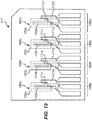
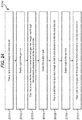
- figure 16 shows a known microfluidic junction B110, an outlet channel B111, and a plurality of circuit units B112, B113, B114.
- a microfluidic junction B110 is an area for converging multiple fluids.
- An outlet channel B111 is capable of receiving fluid from the microfluidic junction B110.
- An outlet channel B111 includes a first end connected with the microfluidic junction B110, a second end connected with a waste reservoir B115, and an analysis region B116 positioned between the first end and the second end of the outlet channel B111.
- Each circuit unit includes a source channel B117 with a first end capable of receiving sample fluid and a second end connected with the microfluidic junction B110; a branch channel B118 connected with the source channel B117 at an intersection B119; and a flow diversion system capable of differentially directing fluid flowing through a source channel either into the microfluidic junction B110 or into a branch channel B118.
- the branch channel B118 is further connected to a waste reservoir B120.
- FIG 16 several dead-legs B108 exist at the intersection of the branch channels B118 with the source channels B117, and at the intersection of the source channel B117 with the outlet channel B111.
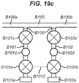
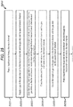
- Figure 17 further illustrates a series of branch channels B101, B102, joining a main channel B100 and the presence of dead-legs B108 in the branch channels B101 and B102 at or near these intersection points.
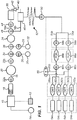
- a fluidic cartridge for processing a liquid sample comprising: a main channel for passing the liquid sample therethrough from an upstream end to a downstream end; and one or more branch channels that join the main channel for introducing liquid and gas into the main channel after the liquid sample has passed downstream of the one or more branch channels, the one or more branch channels including a first branch channel, wherein the first branch channel comprises: a gas inlet for introducing a gas into the first branch channel; a liquid inlet for introducing a liquid into the first branch channel; and a valve configured to move between a closed position in which it prevents liquid and gas in the first branch channel from passing into the main channel and an open position in which it permits liquid and gas in the first branch channel to pass into the main channel, wherein the or each gas inlet is located further from the junction of the branch channel with the main channel than the or each liquid inlet.
- gas may be introduced into the branch and main channels to clear the channels and also push the liquid and sample through the main channel.
- the one or more branch channels further comprises a second branch channel which joins the main channel downstream of the first branch channel, wherein the second branch channel comprises: a gas inlet for introducing a gas into the second branch channel; a liquid inlet for introducing a liquid into the second branch channel; and a valve configured to move between a closed position in which it prevents liquid and gas in the second branch channel from passing into the main channel and an open position in which it permits liquid and gas in the second branch channel to pass into the main channel.
- the second branch channel can be used to introduce a different liquid or reagent into the main channel, and is disposed so that the second liquid can be introduced after the passage of a first liquid from the first branch channel.
- the or each gas inlet on the one or more branch channels preferably comprises a gas inlet valve to prevent liquid and gas flowing from the branch channel through the gas inlet.
- the gas inlet valve reduces the risk of contamination of the gas inlet by the liquid from the liquid inlet.
- the or each valve in the one or more branch channels is spaced from the main channel, thereby forming a dead-leg in the branch channel between the valve and the main channel.
- the introduction of secondary channels intersecting a main channel will typically create 'dead-legs'. These dead-legs act as a contamination risk.
- the presence of the gas inlet and gas inlet valve on the one or more branch channels provides a method to overcome that risk by ensuring that the channels can be cleared of liquid sample and/or liquid before each pass of the next liquid.
- the or each valve in the one or more branch channels may be located at a junction between the branch channel and the main channel. This can reduce the length of the branch channel (as it is not required to accommodate an additional valve), and thus save space on the fluidic device.
- the or each liquid inlet on the one or more branch channels is coupled to a liquid chamber.
- the chamber contains the liquid on the fluidic cartridge, and prevents leakage of the liquid which would detrimentally affect the use of the device.
- the or each liquid chamber is a collapsible blister adapted, when it is collapsed, to eject a liquid contained therein through the liquid inlet, into the branch channel, and into the main channel, for introducing the liquid into the main channel after the liquid sample has passed downstream of the one or more branch channels.
- the blister contains the liquid and provides a mechanism for releasing the liquid into the fluidic device during operation that does not involve externally introducing liquid components.
- the or each liquid chamber preferably contains a reagent or a buffer such as a lysis buffer, a wash buffer or an elution buffer.
- a reagent or a buffer such as a lysis buffer, a wash buffer or an elution buffer.
- These reagents may be capable of performing cell lysis and cleaning the sample as well as ensuring the sample is prepared for analysis.
- the liquid chamber coupled to the liquid inlet in the first branch channel contains a wash buffer
- the liquid chamber coupled to the liquid inlet in the second branch channel contains an elution buffer. Since wash buffers are 'toxic' to subsequent downstream reactions (in particular, they prevent the action of elution buffers) the wash buffer is passed first and then the branch and main channels can be cleaned/evacuated with a gas pass. The elution buffer can then pass through the channels and downstream to the liquid sample.
- the fluidic cartridge comprises a pneumatic interface for connecting to a source of positive and/or gauge pressure, the pneumatic interface comprising a plurality of ports, and wherein the or each valve or gas inlet valve in the one or more branch channels is a pneumatically-actuated valve coupled to at least one port in the pneumatic interface such that it may be actuated by the source of positive and/or gauge pressure.
- the first and second gas inlet valves in the first and second branch channels, respectively are coupled to the same port in the pneumatic interface, such that the first and second gas inlet valves may be actuated simultaneously. This simplifies the operation of the cartridge.
- the or each gas inlet on the one or more branch channels is preferably coupled to the pneumatic interface for connection to a gas supply.
- the or each gas inlet on the one or more branch channels is coupled to the pneumatic interface for connection to a gas supply for passing a gas through the gas inlet, into the branch channel, and into the main channel, for introducing the gas into the main channel after the liquid sample has passed downstream of the one or more branch channels.
- the passing of gas through the branch and main channels effectively evacuates the dead-legs and cleans the channels.
- the gas can further dry the channels of liquid residues.
- the or each pneumatically-actuated valve comprises a valve chamber having first and second openings connected to the branch channel; and a flexible membrane movable between a closed position, in which the flexible membrane seals against the first and second openings to prevent fluid flow through the branch channel, and an open position, in which the flexible membrane is spaced apart from the first and second openings to permit fluid to flow through the branch channel.
- the or each valve further comprises a fluid passageway having an opening in the valve chamber, the opening separated from the first and second openings by the flexible membrane, wherein the fluid passageway is coupled to a port in the pneumatic interface for applying a positive or gauge pressure in the valve chamber to move the flexible membrane between the open and closed positions.
- the fluid passageway in the valve chamber controls the pressure of the chamber, enabling the flexible membrane to act as a valve.
- the pneumatic interface comprises first to third ports, and wherein the first to third ports are respectively coupled to: i) the valve in the first branch channel; ii) the valve in the second branch channel; and iii) the gas inlet valve in the first branch channel and the gas inlet valve in the second branch channel; such that the respective valves may be actuated by the source of positive and/or gauge pressure acting through the respective ports.
- the coupling of the gas inlet valves on the first and second branch channels enables control of these valves simultaneously.
- a method of processing a liquid sample in a fluidic cartridge comprising a main channel and one or more branch channels that join the main channel, including a first branch channel comprising a gas inlet, a liquid inlet and a valve
- the method comprising; a) passing a liquid sample through the main channel; b) supplying a gas to the gas inlet; c) opening the valve on the first branch channel and passing a gas from the gas inlet through the first branch channel and into the main channel to evacuate any residual liquid sample in the first branch channel; d) ceasing the supply of gas; e) passing a liquid from the liquid inlet through the first branch channel and into the main channel; f) supplying a gas to the gas inlet; and g) passing a gas from the gas inlet through the first branch channel and into the main channel to evacuate any residual liquid from the first branch channel.
- This method is particularly effective since the user can rely on the passing of gas through the branch and main channels to evacuate any
- the fluidic cartridge further comprises a gas inlet valve on the first branch channel
- the method steps (b) and (f) of supplying a gas to the gas inlet further comprise opening the gas inlet valve
- step (d) of ceasing the supply of gas further comprises closing the gas inlet valve and before ceasing the supply of gas. This prevents liquid from passing from the liquid inlet and into the gas inlet when a liquid is ejected from the liquid chamber.
- a method of processing a liquid in a fluidic cartridge comprising a main channel having an upstream end and a downstream end and one or more branch channels that join the main channel, including a first branch channel and second branch channel downstream of the first branch channel, each branch channel comprising a gas inlet, a gas inlet valve, a liquid inlet and a valve, the method comprising::
- the method steps (I) and (m) further comprise supplying a gas to the gas inlet on the first branch channel and opening the gas inlet valve on the first branch channel and passing a gas from the gas inlet on the first branch channel through the first branch channel and into the main channel to evacuate any residual liquid in the first branch channel.
- this step ensures that the first branch channel is also cleared of any elution buffer, which is of particular importance when sample and reagent volumes are being controlled.
- the fluidic cartridge may preferably further comprise a pneumatic interface for connecting to a source of positive pressure, and wherein the or each gas inlet on the one or more branch channels is coupled to the pneumatic interface for connection to a gas supply, wherein one or more of the steps of passing a gas from the gas inlet comprises passing a gas from the supply of positive gas pressure into the branch channel.
- the one or more of the steps of passing a gas from the gas inlet on the one or more branch channels and into the main channel further comprises purging the residual liquid sample and/or residual liquid from the main channel. This ensures the total volume of liquid sample and/or liquid is passed to the downstream end of the main channel, which, as stated previously, is important when the liquid volume is to be precisely controlled.
- the or each liquid inlet on the one or more branch channels is coupled to a liquid chamber, and wherein one or more of the steps of passing a liquid from the liquid inlet comprises expelling the liquid from the liquid chamber into the branch channel.
- the or each liquid chamber may preferably be a collapsible blister, and wherein one or more of the steps of passing a liquid from the liquid inlet comprises collapsing the collapsible blister and thereby ejecting liquid contents through the liquid inlet, into the branch channel and into the main channel.
- the step of passing a liquid from the liquid inlet on the first branch channel comprises expelling a wash buffer from the liquid chamber through the liquid inlet into the first branch channel and into the main channel; and wherein the step of passing a liquid from the liquid inlet on the second branch channel comprises expelling an elution buffer from the liquid chamber through the liquid inlet into the second branch channel and into the main channel.
- Embodiments of the invention will now be described in the context of an exemplary fluid cartridge in which the invention is implemented. Whilst not necessary to understand the present invention, it is beneficial to provide general description of the principles of the structure, manufacture, function and use of the fluidic cartridge and associated methods for performing a test.
- the exemplary fluidic cartridge and associated methods chosen to illustrate the present invention are for the detection of Chlamydia trachomatis bacterium using PCR amplification and electrochemical detection.
- the skilled person would understand that the invention is not limited to the exemplary fluidic cartridge and associated methods, and is suitable for use in with various different cartridges for a wide variety of sample analysis techniques or biological assays; for example, assays of target nucleic acid sequences in a liquid sample.
- the exemplary cartridge comprises: a fluidic portion through which the sample flows and in which nucleic acid amplification and detection take place; a pneumatic portion which controls flow through the fluidic portion; and at least two electrodes which provide a potential difference for the detection of an amplified nucleic acid of interest.
- the fluidic portion and pneumatic portion may be constructed of a fluidic layer, a fluidic foil, a pneumatic layer and a pneumatic foil such as those described in relation to the exemplary cartridge below.
- the fluidic portion does not necessarily consist only of a fluidic layer and a fluidic foil and the pneumatic portion does not necessarily consist only of a pneumatic layer and a pneumatic foil.
- the layers may interact to produce the fluidic portion and the pneumatic portion such that parts of all or some of the layers make up each portion.
- the fluidic portion refers to the particular areas of the cartridge which provide the function of allowing controlled sample flow
- the pneumatic portion refers to the particular areas of the cartridge which provide the function of controlling the flow through the fluidic portion.
- the housing, fluidic portion and pneumatic portion are made of plastic.
- plastic is meant a synthetic or natural organic material that may be shaped when soft and then hardened, including resins, resinoids, polymers, cellulose derivatives, casein materials, and protein plastics.
- plastics from which the cartridge may be constructed include, but are not limited to thermoplastics, for example polycarbonate, polyethylene terephthalate, cyclic olefin copolymers such as Topaz, acrylonitrile butadiene styrene, and thermoplastic elastomers, for example polypropylene.
- Plastic housings, fluidic portions and pneumatic portions can include components which are not made of plastic (e.g. blisters made from metal foil, metallic inserts at the sample inlet), but they are formed primarily from plastic. The use of plastic materials facilitates economical manufacture of the cartridges.
- pneumatic and fluidic foils may be made from a metal foil, the preferred materials are plastic including those mentioned above.
- foils are a polyethylene terephthalate / polypropylene composite.
- the target nucleic acid sequence is any nucleic acid to be detected in a sample.
- the target nucleic acid(s) to be amplified and detected in the cartridge will usually be DNA, but it is also possible to amplify and detect RNA.
- a cartridge may permit amplification and/or detection of both DNA and RNA targets.
- the liquid sample is the composition which is introduced into the cartridge in order to determine whether the target nucleic acid(s) of interest is/are present.
- the sample may be a composition in which the nucleic acid to be detected is suspected to be present (e.g. for clinical diagnosis), or may be a composition in which the nucleic acid to be detected is potentially present (e.g. for contamination testing).
- the liquid sample can have various sources. For instance, it can be material obtained from an animal or plant (e.g. for diagnosis of infections or for genotyping). Such samples may be obtained with minimal invasiveness or non-invasively, e.g., the sample may be obtained from an animal using a swab, or may be a bodily fluid. As an alternative, the sample may be material obtained from food or water (e.g. for contamination testing). The sample will usually include cells, and the target nucleic acid (if present) can be extracted from these cells within the cartridge.
- samples can be diluted or otherwise treated prior to being introduced into the cartridge, but it is preferred that the cartridge can handle material which has not been pretreated in this way.
- Vertebrate animals may be mammals. Examples of mammals include but are not limited to mouse, rat, pig, dog, cat, rabbit, primates or the like.
- the animal may be a primate, and is preferably a human.
- the cartridge can be used for clinical diagnosis of human samples.
- the cartridge can analyse a positive and/or negative control to provide confirmation that the cartridge is functioning as expected.
- the control(s) can be introduced into the cartridge by a user, or can be included within a cartridge before use.
- an internal positive control nucleic acid allows a user to identify whether a negative result for the sample has been obtained because the nucleic acid amplification has been unsuccessful (false negative). If the positive control nucleic acid fails to be detected in the detection chamber, despite its presence in an amplification chamber, the user will be able to identify the test as a potential false negative result, and can perform another test.
- an internal negative control allows a user to identify whether a positive result has been falsely obtained because of the presence of contamination.
- a negative control can involve performing PCR in a chamber in which no nucleic acid is provided, or in which a sample undergoes an amplification reaction without necessary components e.g. PCR without primers. If nucleic acid is nevertheless detected in the detection chamber, despite its intended absence in an amplification chamber, the user will be able to identify the test as a potential false positive result, and can perform another test.
- a positive control nucleic acid may be any nucleic acid that will not be found in a sample used in the cartridge.
- the internal control DNA may be taken from a bacterium that is not pathogenic to animals and which contains a nucleic acid that is highly specific to the bacterium.
- One example of a possible bacterium from which the control nucleic acid may be taken for an animal sample is Pectobacterium atrosepticum, although any control nucleic acid may be used that will not be present in a sample.
- the fluidic portion of the cartridge comprises channels and chambers through which sample flows.
- the flow of sample through the cartridge is controlled in two ways.
- the fluidic portion has a gas inlet.
- the gas inlet is connected to a gas supply, and injection of gas into the fluidic portion via this inlet allows the sample to be pushed downstream through the cartridge, towards the detection chamber.
- the gas supply may be provided by the reader.
- the gas supply may be an on-board gas supply.
- the gas supply is provided by an external source and the gas inlet is connected to a pneumatic circuit such that the gas supply is provided via a pneumatic inlet on the cartridge.
- at least one pneumatically controlled valve controls local movement of the sample through the fluidic portion.
- the pneumatically controlled valve(s) may be controlled independently of other pneumatically controlled valves and may be controlled independently of the gas supply that generally causes downstream movement of the sample via the gas inlet.
- the gas inlet and the pneumatically controlled valve(s) also permit sample to be flushed through the fluidic portion e.g. to exclude excess volumes of material.
- the fluidic portion also has an exhaust which allows air and waste material to exit the channels and chambers of the fluidic portion without a build-up of pressure occurring in the cartridge.
- the exhaust comprises a waste chamber and/or a waste vent.
- the fluidic portion of the cartridge includes reagents and/or physical components for cell lysis and nucleic acid separation.
- reagents and/or physical components for cell lysis and nucleic acid separation may be any reagents or physical components that are capable of lysing cells and separating nucleic acids from cell debris and other cellular components.
- they may comprise (i) a lysis buffer which is capable of causing lysis of target cells which may be present in the sample e.g.
- buffers including a detergent such as nonyl phenoxypolyethoxylethanol (available as NP-40) or t-octylphenoxypolyethoxyethanol, (available as Triton X 100), or including guanidine thiocyanate, and/or (ii) a capture support or column which specifically binds nucleic acids but does not bind other undesired cellular components (e.g. proteins and lipids).
- the capture column comprises a capture filter and may additionally comprise a depth filter.
- the filters may be made of glass fibres (available as Whatrnan filters), or may be made of silica, although any column or support which is capable of separating nucleic acids from other cellular components may be used.
- Elution using a wash buffer to remove cell debris and other cellular components, followed by elution using an elution buffer to elute the separated nucleic acids from the capture support or column can be undertaken such that the capture column can separate nucleic acids from cell debris and other cellular components.
- a channel through which the sample flows fluidly connects the sample inlet to at least one amplification chamber where nucleic acid amplification can take place.
- the purpose of the amplification chamber(s) is to permit amplification of any target nucleic acid of interest that is present in the sample (and, where present, any positive control nucleic acid). Any nucleic acid amplification method may be used and these are described in more detail below in relation to an exemplary cartridge.
- the different nucleic acid amplification reagents that are required for different nucleic acid amplification methods are well known in the art.
- reagents are provided in or upstream of the amplification chamber(s) such that the sample (and any positive control) includes all necessary reagents for nucleic acid amplification once it reaches the amplification chamber.
- Adaptation of a nucleic acid amplification method according to the target nucleic acid to be detected is also well known in the art (e.g. design of primers). The skilled person would therefore be able to adapt the reagents for nucleic acid amplification accordingly.
- the term "chamber” does not denote any particular size or geometry, but instead it means a region within the fluidic portion which is designed to permit nucleic acid amplification to occur. Thus, for instance, it could be a region in which the sample can be fluidically isolated (e.g.
- nucleic acid amplification e.g. thermocycling, etc .
- it can be located within the cartridge so that it is in the proximity of any external resources that are needed (e.g. next to a heat source within a cartridge reader, thereby permitting thermal cycling to occur).
- test amplification channels and/or chambers may be included in the cartridge.
- the different test amplification channels and/or chambers may include reagents required to amplify different nucleic acids of Interest. Therefore using multiple amplification test channels and/or chambers allows multiple tests to be performed on a single cartridge, simultaneously (including any controls).
- reagents for amplification of multiple different nucleic acids may be present in a single amplification chamber, and the different nucleic acids (whether multiple target nucleic acids, or a target nucleic acid and a control nucleic acid) may be amplified simultaneously in the same amplification chamber.
- a further channel through which the sample flows after nucleic acid amplification fluidly connects the at least one amplification chamber to at least one detection chamber where the results of nucleic acid amplification can be detected.
- reagents for nucleic acid detection In or upstream of the detection chamber are reagents for nucleic acid detection such that the sample includes all necessary reagents for the detection once it reaches the detection chamber.
- the reagents for nucleic acid detection may be specific for the particular target nucleic acid, i.e. they may allow for detection of the presence of the specific nucleic acid sequence.
- the reagents for nucleic acid detection may be generic reagents to detect the presence of any nucleic acids.
- Such generic reagents may be used if all nucleic acids other than the target nucleic acid are removed prior to detection. For example, this may be achieved by providing a nuclease that is capable of hydrolysing all nucleic acids present in the sample other than the target nucleic.
- the amplified target nucleic acid can be protected from hydrolysis, for example by inclusion of chemical modifications in the primers which are incorporated into the amplified product and which cannot be hydrolysed.
- Reagents for nucleic acid detection are described below in relation to an exemplary cartridge but usually comprise a probe including a label. The probe is capable of hybridising to the amplified nucleic acid which has been amplified in the amplification chamber(s).
- the detection of the nucleic acid may occur via a detectable change in the signal from the label.
- the change may be caused by hydrolysis of the probe.
- hydrolysis is usually achieved using a double strand specific nuclease, which can be an exonuclease or an endonuclease.
- the nuclease is T7 endonuclease.
- the signal from the label is capable of undergoing a change following hydrolysis of the probe.
- the reagents for nucleic acid detection will additionally include a positive control probe including a label.
- the positive control probe is capable of hybridising to the amplified control nucleic acid.
- the signal provided by the labels of the positive control and target probes may be the same, but present in separate detection chambers such that the signals corresponding to the control and test nucleic acids can be distinguished.
- the signal provided by the labels of the control and target probes may be different, such that the signals are distinguishable from one another, even if the probes are present in the same detection chamber.
- test detection channels and/or chambers may be included in the cartridge.
- the different test detection channels and/or chambers may include reagents required to detect different nucleic acids of interest. Therefore using multiple detection test channels and/or chambers allows multiple tests to be performed on a single cartridge, simultaneously.
- reagents for detection of multiple different nucleic acids may be present in a single detection chamber, and the different nucleic acids (whether multiple target nucleic acids or a target nucleic acid and a control nucleic acid) may be detected simultaneously in the same detection chamber.
- the label is detectable by use of the cartridge's electrodes, and so the label will usually be an electrochemical label, such as a ferrocene.
- electrochemical label such as a ferrocene.
- Examples of labels which may be used can be found in WO03/074731 , WO2012/085591 and PCT/GB2013/051643 . Signal emitted by the label can be detected by a cartridge reader.
- the pneumatic portion of the cartridge comprises at least one pneumatic circuit which each control at least one pneumatically controlled valve.
- the pneumatic portion controls sample flow through the cartridge by the opening and closing of pneumatically controlled valves.
- the opening and closing of the valves is controlled by changes in pneumatic pressure in the pneumatic circuit that is applied through a pneumatic pressure inlet.
- the cartridge contains many pneumatically controlled valves.
- the pneumatically controlled valves may be controlled by separate pneumatic pressure inlets. These valves can be used to prevent downstream movement of sample through the fluidic portion until necessary steps have been performed and/or to prevent unwanted reverse movement of sample upstream.
- a valve may be provided upstream of the at least one amplification chamber in order to prevent downstream movement into the at least one amplification chamber until cell lysis and nucleic acid separation has taken place. Following cell lysis and nucleic acid separation the valve upstream of the at least one amplification chamber may be opened in order to allow downstream flow. It can then be closed again, to prevent backflow out of the chamber back towards the sample inlet.
- the cartridge comprises at least two electrodes which can provide a potential difference across the at least one detection chamber.
- the potential difference causes current to flow through the at least one detection chamber, thereby permitting the detection of signal from electrochemically active labels.
- the exemplary cartridge described below is intended to be a single-use, disposable cartridge for performing a test on a sample introduced into the cartridge.
- the exemplary cartridge is a fluidic cartridge with channels of an appropriate scale (as detailed hereafter). However, the invention may be performed on a microfluidic device, or an LOC. Once the test has been run, it is preferred that the cartridge is disposed of. However, if desired, the cartridge may be sent for re-processing to enable it to be used again
- the cartridge comprises all of the biological agents necessary for conducting the test of choice.
- the exemplary cartridge is used for detecting the presence, absence or amount of a pathogen of interest. Any pathogen may be detected. Examples of pathogens which may be detected by the cartridge are Chlamydia trachomatis, Trichomonas vaginalis, Neisseria gonorrhoea, Mycoplasma genitalium and methicillin resistant Staphylococcus aureus.
- the cartridge comprises reagents for nucleic acid amplification. Nucleic acid amplification may be performed using any nucleic acid amplification method.
- the nucleic acid amplification method may be a thermocycling method in which the temperature at which the method is performed is varied such that different steps of the amplification are able to take place at different temperatures within the cycle. For example melting, annealing of primers and extension may each be performed at different temperatures. By cycling through the temperatures, the timing of each of the steps of the method can be controlled.
- the nucleic acid amplification may be an isothermal method in which the temperature is kept constant. In both the thermocycling and the isothermal nucleic acid amplification methods, the temperature is controlled during nucleic acid amplification.
- nucleic acid amplification methods are the polymerase chain reaction (PCR), the ligase chain reaction (LCR), strand displacement amplification (SDA), transcription mediated amplification, nucleic acid sequence-based amplification (NASBA), helicase-dependent amplification and loop-mediated isothermal amplification.
- PCR polymerase chain reaction
- LCR ligase chain reaction
- SDA strand displacement amplification
- NASBA nucleic acid sequence-based amplification
- loop-mediated isothermal amplification The reagents for nucleic acid amplification will vary depending of the nucleic acid amplification method used but include a polymerase and nucleotide triphosphates.
- the cartridge also comprises detection reagents which are capable of detecting the presence or absence of amplified nucleic acids which are the product of the nucleic acid amplification method.
- the reagents for nucleic acid detection comprise a probe which is capable of hybridising to the amplified nucleic acid.
- the probe includes a ferrocene label.
- the detection of the nucleic acid occurs via a detectable change in the signal from the label.
- the change is caused by hydrolysis of the probe, which is achieved using a double strand specific nuclease.
- the nuclease is a T7 endonuclease.
- the ferrocene gives different electrochemical signals when it is part of a probe or when it is attached only to a single nucleotide, and so hydrolysis is easily detected.
- the change in signal from the label permits detection of the presence of the nucleic acid of interest.
- the electrodes allow the detectable change in the signal from the label, which occurs in the presence of the target nucleic acid, to be detected.
- the cartridge is configured for use with a cartridge reader (not shown).
- the cartridge comprises a number of pneumatic, mechanical, thermal and electrical interfaces (described in more detail below) through which the reader interacts with the cartridge to perform the test.
- the cartridge would be inserted into the reader, and the reader would be activated to begin interacting with the cartridge via the interfaces to perform the test.
- it is not necessary to describe exactly how the cartridge interacts with the reader to conduct a particular test and provide the test results, but an overview of an exemplary operation of a cartridge is provided hereafter.
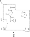
- the 'fluid pathway' which has an upstream end and a downstream end.
- 'downstream' generally refers to the direction of flow of the liquids
- 'upstream' refers to the direction opposite the direction of flow.
- the fluid pathway in the exemplary cartridge may have different branches (and thus form different fluid pathways), but all pathways have a recognisable direction of flow which permit a skilled person to identify the upstream and downstream directions.
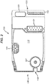
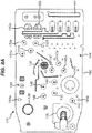
- the liquid sample is introduced into the cartridge at a sample mixing chamber 10 through an entry port.
- a particular arrangement of a preferred entry port may itself form an isolated inventive aspect of the cartridge, as described further in section 3, below.
- a sample indicator 12 is fluidly coupled to the sample mixing chamber 10 such that a sample introduced into the sample mixing chamber 10 is visible in the sample indicator 12.
- a blister 14 containing a lysis buffer is also connected to the sample mixing chamber 10 .
- the lysis buffer comprises guanidine thiocyanate.
- a coarse filter 18 Downstream of the sample mixing chamber 10, along a main channel 16, is a coarse filter 18.
- the coarse filter 18 filters out any large debris in the liquid sample, such as skin or bodily hair, as the liquid sample passes through main channel 16.
- a bellows 20 Downstream of the coarse filter 18, along the main channel 16, is a bellows 20 having an upstream bellows valve 22a and a downstream bellows valve 22b.
- the bellows 20, together with its upstream and downstream valves 22a-b is capable of pumping the liquid sample from the upstream end of the fluid pathway (i.e. from the sample mixing chamber 10) to the downstream end.
- this is achieved by virtue of flexible membranes within the bellows 20 and the upstream and downstream bellows valves 22a-b which actuate to create local pressure differentials to, on the one hand, draw in the liquid sample from the sample mixing chamber 10 into the bellows 20 and, on the other hand, from the bellows 20 further downstream through the main channel 16.
- This is achieved by carefully choreographed pneumatic actuation of the flexible membranes in the valves.
- Particular arrangements of a preferred valve may themselves form isolated inventive aspects of the cartridge, as described further in section 3, below.
- a capture column 24 Downstream of the bellows along the main channel 16 is a capture column 24.
- the purpose of the capture column 24 is to separate nucleic acids from cell debris and other cellular components.
- the capture column comprises a capture filter and a depth filter both made of glass fibres.
- a particular arrangement of a preferred capture column may itself form an isolated inventive aspect of the cartridge, as described further in section 3, below
- Two branch channels 26, 28 join the main channel 16 between the downstream bellows valve 22b and the capture column 24.
- the purpose of the branch channels Is to introduce liquid buffers necessary for performing the desired test. For example, with the test conducted by the exemplary cartridge, it is necessary to introduce an elution buffer and a wash buffer into the main channel once the sample has passed through.
- the wash buffer is contained in a wash buffer blister 30 and the elution buffer is contained in an elution buffer blister 32.
- the introduction of the wash buffer and elution buffer into the main channel 16 is controlled by wash buffer valve 34 and elution buffer valve 36, respectively.
- wash and elution buffer blisters 30, 32 are collapsed so as to expel the wash and elution buffers into the branch channels 26, 28 and thence into the main channel 16 through the wash and elution buffer valves 34, 36.
- a waste chamber 38 Downstream of the capture column 24, along a waste branch 16a of the main channel 16, is a waste chamber 38.
- a particular arrangement of a preferred waste chamber may itself form an isolated inventive aspect of the cartridge, as described further in section 3, below.
- the purpose of the waste chamber 38 is to collect the cell debris and cellular components other than nucleic acids and contain them, thereby preventing them from entering the test channel 54a or the control channel 54b.
- the waste chamber 38 is vented to atmosphere through a waste vent 40, and an aerosol impactor 42 is provided between the waste chamber 38 and the waste vent 40 to prevent particulate matter from escaping from the waste chamber 38 into the atmosphere.
- a waste chamber valve 44 in the main channel waste branch 16a of the main channel 16 permits and prevents fluids passing into the waste chamber 38 at appropriate points during the test.
- an elution chamber 46 Downstream of the capture column 24, along an elution branch 16b of the main channel 16, is an elution chamber 46.
- the purpose of the elution chamber 46 is to allow the sample preparation to settle and for bubbles to disperse before the sample enters the amplification chambers.
- An elution chamber valve 48 in the elution branch 16b of the main channel 16 permits and prevents fluids passing into the elution chamber 46 at appropriate points during the test.
- a convoluted mixing channel 52 Downstream of the elution chamber 46 is a convoluted mixing channel 52. Here the prepared sample is mixed prior to passing through the isolation valve 50.
- the components upstream of the isolation valve 50 are referred to as being comprised in the 'front end' of the cartridge, whilst the components downstream of the isolation valve 50 are referred to as being comprised in the 'back end' of the cartridge.
- the liquid sample is prepared for analysing in the front end of the cartridge, and the analysis is carried out on the sample in the back end of the cartridge.
- the isolation valve 50 is open to permit the prepared liquid sample to pass from the front end to the back end of the cartridge. At an appropriate point in the test, after the liquid sample has been prepared and is within the back end of the cartridge for analysis, the isolation valve 50 is closed to prevent any of the sample from re-entering the front end. Once the isolation valve 50 is closed, it cannot be opened again.
- the isolation valve 50 also acts as a safeguard in case of a power failure, wherein the reader closes the isolation valve 50 to prevent leakage.
- each of the amplification channels 54a-b comprises an amplification chamber 56a-b having an amplification chamber inlet valve 58a-b and an amplification chamber outlet valve 60a-b.
- Any nucleic acid amplification method may be performed in the nucleic acid amplification chamber. If PCR is used, the nucleic acid amplification chambers contain a thermostable DNA polymerase, dNTPs, a pair of primers which are capable of hybridising to the nucleic acid to be amplified.
- the nucleic acid amplification chambers may additionally contain buffer salts, MgCl 2 , passivation agents, uracil N-glycosylase and dUTP.
- buffer salts MgCl 2
- passivation agents uracil N-glycosylase
- dUTP dUTP
- thermostable DNA polymerase is Taq polymerase from Thermus aquaticus.
- Each of the nucleic acid amplification chambers in the exemplary cartridge comprises reagent containment features in the form of first and second shallow wells formed in the fluidic layer.
- the reagents to be used in the cartridge are spotted in the wells.
- the test-specific reagents and the generic reagents are isolated from each other by spotting each in a different well.
- the test-specific reagents are spotted in a first well in the chamber and the generic reagents are spotted in a second well in the chamber.
- the ratio of nucleic acid amplification chambers to detection chambers is 1:2.
- the prepared sample enters the back end of the cartridge at the isolation valve 50 and is split into two nucleic acid amplification chambers. After processing, the each of the two processed measures of sample from the nucleic acid amplification chamber is split into two detection chambers. Therefore, for each sample introduced into the exemplary cartridge, four detection chambers may be filled from two nucleic acid amplification chambers, thus facilitating duplex amplification and 4-plex detection.
- one or three or more nucleic acid amplification chambers may be provided to provide any level of multiplexing desired, and that the number of the detection chambers provided may be adjusted accordingly to maintain a 1:2 ratio of nucleic acid amplification chambers to detection chambers.
- the ratio 1:2 is preferred for the exemplary cartridge because such a ratio allows twice the number of target nucleic acids to be assayed compared to the number of different labels required for detection in the detection chambers.
- the ratio may be changed depending on the number of labels and PCR targets for the liquid sample. For instance, the ratio may be 1:1, 1:3 or 1:n such that there are n detection chambers branching from the main channel of each fluid pathway when there are n times as many multiplexed PCR targets for the number of labels.
- PCR primers specific for Chlamydia trachomatis are dried down in the amplification chamber in the amplification test channel together with the other reagents required for nucleic acid amplification.
- PCR primers specific for a positive control nucleic acid are dried down in the amplification chamber in the amplification control channel together with the other reagents required for nucleic acid amplification.
- a positive control nucleic acid is also provided in the amplification chamber in the amplification control channel, taken from Pectobacterium atrosepticum. The dried down reagents are reconstituted when the liquid sample reaches them.
- each of the amplification channels 54a-b Downstream of the amplification chamber outlet valves 60a-b each of the amplification channels 54a-b splits into two further detection channels, leading to two detection chambers for each amplification chamber, giving a total of four detection chambers 62a-d in total.
- the reagents for nucleic acid detection, including the target probe are dried down in the detection chambers 62a-d downstream of the test amplification chamber 56a or 56b.
- the reagents for nucleic acid detection including the control probe are dried down in the detection chambers downstream of the control amplification chamber 56a or 56b (whichever is not the test chamber mentioned above).
- Each detection chamber 62a-d is provided with its own gas spring 64a-d which forms a dead end at the downstream end of the fluid pathway.
- Reagents for nucleic acid detection are provided in detection chambers.
- the reagents for nucleic acid detection include probes having a ferrocene label. These probes are capable of hybridising to the amplified nucleic acids. Following hybridisation of the probes to the amplified nucleic acids, the probes are hydrolysed by a double strand specific nuclease which causes the label to be freed from the rest of the probe. As explained above, freeing of the label from the rest of the probe causes a detectable change in the signal from the label.
- the control probe is provided in separate detection chambers to the target probe and detection of the target nucleic acid and the control nucleic acid take place in different detection chambers, such that the signals are distinguishable from one another.
- bypass channels 66a-b Downstream of the amplification outlet valves 60a-b, but upstream of the forks creating the four detection channels, two bypass channels 66a-b respectively join the two amplification channels 54a-b.
- the purpose of the bypass channels 66a-b is to remove excess liquid sample within the amplification channels 54a-b before the liquid sample enters the detection chambers 62a-d.
- the bypass channels 66a-b connect to a bypass valve 68, which is also fluidly coupled to the elution chamber branch 16b of the main channel 16, downstream of the isolation valve 50, before the channel splits into amplification channels 54a and 54b.
- a particular arrangement of a preferred chamber in the cartridge may itself form an isolated inventive aspect of the cartridge, as described further in section 3, below.
- amplification chambers and the number of detection chambers in the exemplary cartridge may vary depending on the preferred implementation.
- other configurations of channels, chambers, valves and so on are possible without departing from the scope of the invention, as defined by the claims.
- FIG. 2 An exemplary cartridge is shown in figure 2 . As described above, the reader interacts with the cartridge through a plurality of interfaces.
- the interfaces shown in the exemplary cartridge 100 are: a pneumatic interface 101; an electrical interface 102; a bypass valve interface 103; and an isolation valve interface 104. Each of these interfaces is described in more detail below. It will be appreciated that more or fewer interfaces could be provided, depending on the preferred implementation.
- thermal interface allows the temperature of the amplification chambers to be regulated to allow nucleic acid amplification to take place.
- the exemplary cartridge 100 shown in figure 2 comprises an insertion end 105 for insertion into the reader, and a non-insertion end 106. Proximate the non-insertion end 106 is a sample inlet 107 for introducing a sample into the sample mixing chamber 10.
- the sample will usually include cells, and the target nucleic acid (if present) can be extracted from these cells, but other fluid samples such as swab eluate, urine, semen, blood, saliva, stool sweat and tears could be used in other implementations.
- the sample may be introduced into the sample mixing chamber 10 through the sample inlet 107 using a pipette, for example.
- the exemplary cartridge 100 and reader are configured such that when the cartridge is inserted into the reader, all of the aforementioned interfaces are actuatable by the reader.
- the sample inlet 107 remains external to the reader such that a sample may be introduced into the sample mixing chamber 10 whilst the cartridge is inserted into the reader.
- the exemplary cartridge 100 shown in figure 2 further comprises a sample indicator window 109, through which the sample indicator 12 is visible to determine whether a sample has been introduced into the sample mixing chamber 10.
- All of the pneumatic, mechanical and electrical interfaces in the exemplary cartridge 100 are located on the same face of the cartridge, in this case the top face 110.
- the thermal interface (not shown) is provided on the bottom face of the cartridge. This simplifies the design of the reader, which may this provide the associated pneumatic, mechanical and electrical parts which interact with those interfaces in the same region of the reader, thereby making best use of space. It also enables the thermal part of the reader to be provided away from the pneumatic, mechanical and electrical parts.
- the exemplary cartridge 100 shown in figure 2 is formed from various components which shall now be described.
- Figure 3 shows an exploded view of the exemplary cartridge 100 of figure 2 .
- the cartridge 100 comprises, from top to bottom, a housing 111, a blister sub-assembly 112, a pneumatic, foil 113, a pneumatic layer 114, a fluid layer 115 and a fluidic foil 116.
- Also shown in figure 3 is an electrode layer 117, two filters 118 and a plurality of absorbent pads 119, which will be described in more detail below.
- the housing 111 is manufactured from acrylonitrile butadiene styrene.
- the pneumatic and fluidic foils 113, 116 are manufactured from a polyethylene terephthalate / polypropylene composite.
- the pneumatic and fluidic layers 114, 115 are manufacture from polypropylene.
- each of the components mentioned in the previous paragraph is adhered to its adjacent component or components.
- the blister sub-assembly 112 is adhered to the pneumatic foil 113, which is adhered to the pneumatic, layer 114, which is adhered to the fluidic layer 115, which is adhered to the fluidic foil 116.
- the electrode layer 117 is adhered to fluidic layer 115 also.
- the adhesion of the layers to each other provides a series of fluid-tight channels in the cartridge, together with associated chambers, valves, pumps, bellows and other components.
- the channels passing a liquid sample therethrough are liquid-tight and the channels passing a gas therethrough are gas-tight.
- all components are both liquid tight and gas-tight.
- recesses and openings formed in one or both sides of the pneumatic and fluidic layers create, when sandwiched together and adhered to the pneumatic and fluidic foils, respectively, the shapes necessary to provide the aforesaid channels, chambers, valves, pumps, bellows and other components.
- FIG. 4 shows housing 111 in more detail.
- housing 111 comprises a generally rectangular upper surface 120 and walls 121 depending therefrom on all four sides (two of which are visible in figure 4 ).
- a principal purpose of the housing 111 is to protect certain components of the cartridge, most notably the blister sub-assembly 112 and the isolation valve interface 104. It will therefore be noted that the housing 111 is shorter than the pneumatic and fluidic layers 114, 115 such that it overlies only a portion of those layers when the cartridge 100 is assembled. In the exemplary cartridge 100, the pneumatic interface 101, electronic interface 102, and bypass valve interface 103 are not covered by the housing 111 to provide ease of access by the reader.
- the upper surface 120 of the housing 111 has three apertures 122a-c therein, each having walls depending from the peripheries of the apertures to form, when the cartridge is assembled, three recesses.
- the purpose of the recesses is to house the blisters of the blister sub-assembly 112 such that the blisters may be accessed and pressed by the reader, but are otherwise protected from accidental impact.
- the housing 111 comprises three corresponding apertures 122a-c forming three corresponding recesses. It will be appreciated that more or fewer blisters, apertures and recesses may be provided, depending on the preferred implementation.
- the housing 111 could comprise a single aperture forming a single recess housing all available blisters.
- the side walls 121 of the housing 111 which run along the length of the housing 111 between the insertion end 105 and the non-insertion end 106 of the cartridge 100 comprise flanges 123 along at least a portion of their lower edges.
- the purpose of the flanges 123 is two-fold. Firstly, they comprise one or more windows 124a-b for receiving a corresponding number of tabs formed in the pneumatic, layer 114 to hold the cartridge 100 together.
- the flanges 123 are dimensioned so as to protrude beyond the lower surface of the fluidic foil 116 when the cartridge is assembled, such that the fluidic foil 116 is suspended above a flat surface on which the cartridge 100 is placed. This prevents accidental damage to the fluidic foil 116 which could otherwise result.
- flanges 123 are provided along substantially the length of two opposing sides of the cartridge, it will be appreciated that flanges may be provided along three or four edges of the cartridge and still suspend the foil above a flat surface on which the cartridge is placed.
- the cartridge depicted in figure 4 shows flanges 123 extending along substantially the entire length of the edge, a flange which extends only partially along an edge may be provided, or multiple flanges may be provided along each edge.
- the housing 111 further comprises, at the non-insertion end 106, a grip 125 to facilitate insertion of the cartridge into and removal of the cartridge 100 from the reader by hand.
- the grip 125 comprises a series of ridges and grooves formed in the housing 111, but alternative structures to increase friction, such as knurls, are also possible.
- the housing 111 further comprises a sample inlet aperture 126 through which a sample may be introduced into the sample mixing chamber 10 of the cartridge 100 using a pipette, for example.
- a sample inlet aperture 126 Surrounding the inlet aperture 126 for a given diameter is a basin 127 recessed into the upper surface 120 of the housing 111 to accommodate a certain amount of spillage of the liquid sample. Whilst the basin 127 of the exemplary embodiment is substantially flat, it may be sloped toward the inlet aperture 126, such that any spillage drains through the inlet aperture 126.
- the exemplary housing 111 further comprises a plurality of cut-outs: a first cut-out 128 forming the sample window 109, and a second cut-out 129 to provide access to the isolation valve interface 104.
- a first cut-out 128 forming the sample window 109
- a second cut-out 129 to provide access to the isolation valve interface 104.
- Figure 5 shows the blister sub-assembly 112 in more detail.
- the blister sub-assembly 112 may be manufactured separately, during which the blisters are pre-filled with the liquid reagents necessary for conducting the preferred test, and subsequently adhered to the pneumatic foil 113.
- a blister is a collapsible chamber for containing a liquid, which may be expelled from the blister by pressing on the blister and thereby collapsing it.
- the chamber of a blister is sealed by a foil or other frangible layer which ruptures once the pressure inside the chamber reaches a particular magnitude as the blister is collapsed.
- the blister sub-assembly 112 comprises three blisters 130a-c. These contain, respectively, the lysis buffer which comprises reagents capable of performing cell lysis, the wash buffer and the elution buffer.
- the exemplary blister sub-assembly 112 comprises a substrate 131 onto which the aforementioned blisters 130a-c are formed by a deformable polymeric layer which is shaped to provide the chambers. Three apertures 132a-c, corresponding to the three blisters 130a-c, pass through the substrate 132. Each of the apertures is covered by the deformable polymeric layer forming the chamber, which thereby connects the aperture to the chamber but for a seal 133a-c between the respective apertures 132a-c and chambers.
- the seal 133a-c breaks, thereby causing the liquid contents of the blister to be ejected from the blister and to flow through the aperture 132a-c in the substrate 131 out of the blister sub-assembly.
- the seals 133a-c at least partially surround the periphery of the chambers, where they meet the substrate 131.
- the seal 133a-c may be weaker than the rest of the periphery. This ensures that the correct part of the seal 133a-c breaks when the suitable pressure is applied.
- the blisters may be collapsed by the reader when the cartridge is inserted therein.
- One or more mechanical actuators (such as a foot) may be applied by the reader into the recess so as to collapse the blister.
- the blister sub-assembly 112 further comprises two reference holes 134a-b configured to permit an assembly fixture to provide a reference to facilitate positioning of the assembly during manufacture.
- Figures 6A and 6B show the pneumatic layer 114 in more detail.
- Figure 6A is a top view of the pneumatic layer and
- Figure 6B is a bottom view.
- the pneumatic layer 114 is comprised of a rigid plastic layer 135 which, in certain places, is overmoulded with a plurality of flexible membranes to form certain components when the cartridge is assembled.
- the flexible membranes are manufactured from a thermoplastic elastomer.
- the rigid plastic layer 135 has a plurality of differently-shaped recesses therein and apertures therethrough. In combination with the fluidic layer 115, certain recesses within, and/or apertures through, the rigid plastic layer 135 form a number of components, including: the sample mixing chamber 136; the waste chamber 137; the capture column 138; the elution chamber 139; the first and second amplification chambers 140a-b; and the first to fourth detection chambers 141 a-d. An aperture 142 is also provided to give access to the electrode layer 117.
- certain other apertures through the rigid plastic layer form a number of other components, including: the upstream bellows valve 142; the bellows 143; a pneumatic interface 144; the downstream bellows valve 145; the wash buffer inlet valve 146; the wash buffer air inlet valve 146a; the elution buffer inlet valve 147; the elution buffer air inlet valve 147a; the waste chamber valve 148; the elution chamber valve 149; the isolation valve 150; the first and second amplification chamber inlet valves 151a-b; and first and second amplification chamber outlet valves 152a-b.
- a further aperture, in combination with an overmoulded flexible membrane forms a bypass valve 153.
- the valves formed in the pneumatic layer are pneumatically-operable valves. That is, each valve is operable to open and close a fluidic channel in which the valve is located, and this valve is actuated by applying a particular pressure to a pneumatic control line coupled to the valve.
- the pneumatic control lines are coupled to the pneumatic interface 144, to which the reader has access when the cartridge 100 is inserted therein. Hence, to actuate a given pneumatic valve, the reader merely applies an appropriate pressure to the pneumatic control line associated with that valve to open or close the valve.
- the isolation valve 150 and the bypass valve 153 are also actuated by the reader, but mechanically. Again, each valve is operable to open and close a fluidic channel in which the valve is located, but the valve is actuated by applying one or more mechanical actuators (such as a foot) to the valve.
- the pneumatic layer further comprises two reference holes 154a-b configured to permit an assembly fixture to provide a reference to facilitate positioning of the layer during manufacture.
- the reference holes 154a-b in the pneumatic layer align with the reference holes 134a-b in the blister sub-assembly.
- the pneumatic layer further comprises apertures 155a-c which, when the cartridge is assembled, line up with apertures 132a-c passing through the substrate 131 of the blister sub-assembly (through the pneumatic foil, as described below)
- Figure 7 shows the pneumatic foil 113 in more detail.
- the pneumatic foil 113 is adhered to the upper surface of the pneumatic layer 114, thereby fluidly sealing channels, chambers, valves, pumps, bellows and other components formed therein.
- the pneumatic foil 113 is a generally rectangular and planar foil sheet so as to provide an effective seal.
- the pneumatic foil 113 is inert such that is does not react with the reagents which move through the pneumatic layer 114.
- the pneumatic foil 113 does not overlie the entire pneumatic layer 114.
- the pneumatic foil 113 does not overlie the sample mixing chamber 136 or the waste chamber 137 at the non-insertion end 106 of the cartridge 100, or the bypass valve 153 at the insertion end 105.
- the pneumatic foil 113 comprises cut-outs 156, 157, such that it does not overlie the isolation valve 150 or the pneumatic interface 144, respectively.
- the pneumatic foil 113 further comprises three apertures 158a-c which, when the cartridge 100 is assembled, line up with apertures 132a-c passing through the substrate 131 of the blister sub-assembly and 155a-c passing through the pneumatic layer 114.
- the apertures 158a-c permit the liquid reagents within the blisters to pass to the pneumatic layer 114, and thence to the fluidic layer 115 through apertures 155a-c.
- the pneumatic foil 113 comprises two reference holes 159a-b configured to permit an assembly fixture to provide a reference to facilitate positioning of the layer during manufacture.
- the reference holes 159a-b in the pneumatic foil align with the reference holes in the other layers.
- the pneumatic foil is a composite foil manufactured from a layer of polyethylene terephthalate, to provide strength, with a layer of polypropylene on top to provide an inert material for contacting the liquid sample and buffers, and also to enable the foil to be heat sealed to the pneumatic layer (also manufactured from polypropylene.
- Figures 8A and 8B show the fluidic layer 115 in more detail.
- Figure 8A is a top view of the pneumatic, layer and Figure 8B is a bottom view.
- the fluidic layer 115 is comprised of a rigid plastic layer 160.
- the top side of the fluidic layer 115 (not shown) is adhered to the bottom side of the pneumatic layer 113 (see figure 5B ) such that the various channels, chambers, valves, pumps, bellows and other components formed by a combination of the pneumatic and fluidic layers are aligned.
- the rigid plastic layer 160 of the fluidic layer 115 has a plurality of differently-shaped recesses therein and apertures therethrough.
- certain recesses within, and/or apertures through, the rigid plastic layer 160 forms certain components, including: the sample inlet chamber 136; the capture column 138; the elution chamber 139; the first and second amplification chambers 140a-b; and the first to fourth detection chambers 141a-d.
- An aperture 161 is also provided to give access to the electrode layer 117.
- recesses in the fluidic layer 115 also provides the coarse filter 162, the convoluted mixing channel 163, and a plurality of channels which, when the cartridge is assembled, connect the aforementioned components together to enable passage of the liquid sample and liquid reagents through the cartridge, and facilitate pneumatic actuation of the valves, pumps, bellows and other components.
- the fluidic layer comprises two reference holes 164a-b configured to permit an assembly fixture to provide a reference to facilitate positioning of the layer during manufacture.
- the reference holes 164a-b in the fluidic layer align with the reference holes in the other layers.
- the pneumatic interface comprises 11 ports which are connected to the various components as follows.
- Figure 9 shows the fluidic foil 116 in more detail.
- the fluidic foil 116 is adhered to the lower surface of the fluidic layer 115, thereby fluidly sealing channels, chambers, valves, pumps, bellows and other components formed therein.
- the fluidic foil 116 is a generally rectangular and planar foil sheet so as to provide an effective seal.
- the foil 116 is inert such that is does not react with the reagents which move in the pneumatic layer.
- the fluidic foil 116 does not overlie the entire fluidic layer 115. In particular, the fluidic foil 116 does not overlie the detection chambers 141 a-d at the insertion end 105.
- the fluidic foil 116 comprises two reference holes 165a-b configured to permit an assembly fixture to provide a reference to facilitate positioning of the layer during manufacture.
- the reference holes 165a-b in the fluidic foil align with the reference holes in the other layers.
- the fluidic foil is a composite foil manufactured from a layer of polyethylene terephthalate, to provide strength, with a layer of polypropylene on top to provide an inert material for contacting the liquid sample and buffers, and also to enable the foil to be heat sealed to the fluidic layer (also manufactured from polypropylene.
- FIG 10 shows the electrode layer 117 in more detail.
- the electrode layer 117 is adhered to the fluidic layer 115.
- the electrode layer 117 comprises four sets of detection electrodes 166a-d.
- Each set of detection electrodes 166a-d comprises first to third electrical contacts 168a-d which couple with corresponding electrical contacts in the reader when the cartridge is inserted therein.
- the electrical contacts are made of silver to optimise the electrical connection.
- electrodes which are silver plated with silver chloride are used to ensure a the optimal galvanic behaviour.
- Each set of detection electrodes 166a-d comprises a working electrode 169a-d; a counter electrode 170a-d and a reference electrode 171 a-d. Each of the electrodes is coupled to a respective electrical contact. Each set of detection electrodes 166a-d also comprises a dielectric 172a-d covering the interface between the electrodes and the respective electrical contacts.
- electrochemical signalling may be used to indicate the presence of genetic or immuno targets.
- this process is performed in the first to fourth detections chambers 141a-d which are optimised to provide the electrochemical test interface.
- the electrodes 166a-d are arranged such that a liquid sample within the first to fourth detection chambers 141a-d comes into contact with the first to fourth sets of electrodes 166a-d.
- some compounds in the fluid sample referred to as the 'electrolyte'
- This galvanic effect is how batteries work.
- the current required to maintain a given redox state in the detection chambers 141a-d is monitored at different redox states.
- Current is supplied through the electrolyte from the working electrodes 169a-d to counter electrodes 170a-d.
- the reference electrodes 171 a-d also contact the electrolyte. Voltages are declared with respect to this reference electrode because its voltage is largely independent of the redox conditions and this therefore means that it is only the redox state of the chemistry at the control electrode that is being measured.
- a voltage sweep is applied between the working electrodes 169a-d and counter electrodes 170a-d by the reader, which generates the characteristic range of redox conditions.
- the current passing between the working electrodes 169a-d and the counter electrodes 170a-d is then measured to obtain the test results.
- the voltage sweep is a slowly incrementing set of voltages applied between the electrodes. Preferably the sweep is from about -0.7 volts to about +1 volts relative to the reference electrode.
- the voltage is applied in consecutive incrementing pulses having a pulse modulation amplitude of between 30 and 80 millivolts (preferably between 40 and 60 millivolts; more preferably 50 millivolts).
- the step increment from one pulse to the next is between 1 and 5 millivolts (preferably between 2 and 4 millivolts; more preferably 3 millivolts).
- current measurements in the scale of 100s of nano amps may be obtained.
- the particular arrangement of detection electrodes illustrated in figure 10 may itself form an isolated inventive aspect of the cartridge.
- the counter electrode in a potentiostat is larger than the working electrode to provide an ample supply of surplus electrons.
- having a working electrode which is larger than the counter electrode provides larger signals and improved results by way of increased sensitivity. In other words, having a current flow from a relatively large working electrode to a relatively small counter electrode offers improvements over the conventional arrangement.
- each working electrodes 169a-d is formed in a U-shape and each counter electrode 170a-d is formed in a straight elongate shape between the two prongs of the respective U-shaped working electrode.
- a fluid sample (such as a urine sample) is introduced into the sample mixing chamber 10 using a pipette. A portion of the sample passes to the sample indicator 12 to show that a sample is present in the sample mixing chamber.
- the test may commence. Firstly, the reader will apply a mechanical actuator (such as a foot) to collapse the lysis buffer blister 14. In doing so, the lysis buffer will be expelled into the sample mixing chamber 10 where it will mix with the sample.
- a mechanical actuator such as a foot
- the bellows 20 and its valves 22a-b then moves the liquid sample and lysis buffer back and forth into the sample mixing chamber 10 so as to mix the lysis and sample and to rehydrate the internal control. Following the mixing step, incubation of the sample and lysis buffer occurs to allow cell lysis to take place.
- the bellows 20 and its valves 22a-b will then commence operation to pump the sample from the sample mixing chamber 10, into the main channel 16, through the coarse filter 18 and toward the capture column 24.
- nucleic acids are specifically bound to a filter in the capture column on the basis of their size and charge.
- the unwanted liquid sample passes through to the waste chamber 38.
- the reader applies a mechanical actuator (such as a foot) to collapse the wash buffer blister 30.
- the wash buffer will be expelled into the first branch channel 26, and thence into the main channel 16.
- the bellows 20 and its valves 22a-b will commence operation to pump the wash buffer through the main channel 16 and through the capture column 24 to wash any remaining unwanted cell debris and other cellular components out of the capture column with the wash buffer through to the waste chamber 38, or else the wash buffer will be flushed into the waste chambers using air from the wash and/or elution buffer air inlets.
- the reader applies a mechanical actuator (such as a foot) to collapse the elution buffer blister 32.
- the elution buffer will be expelled into the second branch channel 28, and thence into the main channel 16.
- the bellows 20 and its valves 22a-b will commence operation to pump the elution buffer through the main channel 16 and through the capture column 24 to elute the nucleic acids from the capture column, or else the elution buffer will be flushed into the capture column using air from the wash and/or elution buffer air inlets.
- the prepared liquid sample then passes through to the elution chamber 46; again, either by being pumped or flushed as described above
- the sample settles in the elution chamber 46 allowing bubbles to disperse before entering the amplification chambers.
- the bellows 20 and its valves 22a-b will then commence operation to pump the liquid sample from the elution chamber 46, through the isolation valve 59, through the mixing channel 52 and into the amplification chambers 56a-b, or else the sample will be flushed into the amplification chambers using air from the wash and/or elution buffer air inlets.
- the nucleic acid of interest if present, is amplified such that it is present at a detectable level.
- the control nucleic acid is also amplified such that it is present at a detectable level.
- any nucleic acid amplification method may be used.
- primers specifically hybridise to the nucleic acid of interest and are extended by a thermostable polymerase such as Taq polymerase via the addition of dNTPs to the 3' end of each of the primers. Any excess liquid sample may be removed from the fluid pathway through the bypass channels 68.
- a thermostable polymerase such as Taq polymerase
- the bellows 20 and its valves 22a-b will then commence operation to pump the liquid sample from the amplification chambers 56a-b and into the detection chambers 62a-d, or else the sample will be flushed into the detection chambers using ain from the wash and/or elution buffer air inlets.
- the target probe specifically hybridises to the target amplified nucleic acid of interest and the control probe specifically hybridises to the amplified control nucleic acid.
- the nuclease hydrolyses the target and control probes following hybridisation of the probes to the amplified nucleic acid.
- the hydrolysis of the target and control probes frees the labels from the probes causing a detectable change in the signal from the labels to occur.
- the reader applies a mechanical actuator to the isolation valve 50 to close the valve and isolate the liquid sample in the back end of the device.
- the electrodes provide a potential difference across the at least one detection chamber. Depending on the state of the label (i.e. whether it is attached to the full length probe or the probe has been hydrolysed and it is free or attached to a single nucleotide or short part of the probe), the current that is able to flow through the detection chamber will differ. The electrodes therefore allow detection by the reader of the change in the signal from the label which results from hydrolysis of hybridised probe.
- the following section describes the present invention in more detail with reference to figures 18 to 25 .
- the invention may be implemented in the fluidic cartridge described above, specifically in the portion of the main channel between the bellows 20 and the capture column 24, wherein a plurality of fluids are introduced from branch channels into the main channel.
- the invention may be practiced with a main channel and just a single branch channel, but any number of branch channels may be provided, depending on the preferred implementation.
- Figure 18a illustrates a first embodiment of the invention, comprising main channel B100 and a first branch channel B101.
- the main channel B100 comprises an upstream end B100a and a downstream end B100b, wherein the upstream end B100a is capable of receiving a sample and passing the liquid sample from the upstream end B100a to the downstream end B100b.
- the branch channel B101 joins the main channel B100 in the region of the main channel B100 between these two ends.
- the first branch channel B1 D1 further comprises a gas inlet B101a for introducing a gas into the first branch channel, a liquid inlet B101d for introducing a liquid into the first branch channel, and a valve B101c.
- the valve B101c is configured to move between a closed position in which it prevents liquid and gas in the first branch channel from passing into the main channel and an open position in which it permits liquid and gas in the first branch channel to pass into the main channel.
- Figure 18b illustrates an alternative arrangement of the first embodiment of the invention, wherein the first branch channel further comprises a gas inlet valve B101b to prevent liquid and gas flowing from the first branch channel through the gas inlet B101a.
- the gas inlet valve B101 is configured to move between a closed position in which it prevents liquid in the first branch channel from passing into the gas inlet and an open position in which it permits gas from the gas inlet to pass into the first branch channel.
- the gas inlet valve reduces the risk of contamination of the gas inlet by the liquid from the liquid inlet.
- the gas inlet and gas inlet valve may be coupled together, or in an alternative embodiment the gas inlet and gas inlet valve may be independent.
- Figure 19a illustrates a second embodiment of the invention, wherein the fluidic cartridge includes a main channel B100, a first branch channel B101 and a second branch channel B102.
- the main channel B100 comprises an upstream end B100a and a downstream end B100b, wherein the upstream end B100a is capable of receiving a sample and passing the liquid sample from the upstream end B100a to the downstream end B100b.
- the first branch channel B101 joins the main channel B100 in the region of the main channel B100 between these two ends, and the second branch channel B102 joins the main channel B100 downstream of the first branch channel B101.
- the second branch channel B102 further comprises a gas inlet B102a for introducing a gas into the second branch channel, a liquid inlet B102d for introducing a liquid into the second branch channel, and a valve B102c.
- the valve B102c is configured to move between a closed position in which it prevents liquid and gas in the second branch channel from passing into the main channel and an open position in which it permits liquid and gas in the second branch channel to pass into the main channel.
- Figure 19b illustrates an alternative arrangement of the second embodiment, wherein the first and second branch channels B101, B102 further comprise a gas inlet valve B101b, B102b to prevent liquid and gas flowing from the branch channel through the gas inlet B101a, B102a.
- the gas inlet valve B101b, B102b is configured to move between a closed position in which it prevents liquid in the branch channel from passing into the gas inlet and an open position in which it permits gas from the gas inlet to pass into the branch channel.
- the gas inlet valve reduces the risk of contamination of the gas inlet by the liquid from the liquid inlet.
- the gas inlet and gas inlet valve may be coupled together, or in an alternative embodiment the gas inlet and gas inlet valve may be independent ( figure 19c ).
- the first and second gas inlet valves B101b, B102b in the first and second branch channels, respectively may be actuated simultaneously as described in more detail below.
- branch channels B101 and B102 in figures 18 and 19 are illustrated as joining the main channel at a 90-degree junction, or T-junction.
- the person skilled in the art will appreciate that the one or more branch channels may join the main channel B100 at any other angle, such as at 90 degrees or an acute angle, all of which are covered by the scope of this invention.
- the valves B101c, B102c on the one or more branch channels B101, B102 may be spaced from the main channel B100, thereby forming a dead-leg B108 in the branch channel B101, B102 between the valve and the main channel B100 ( figure 18 and 19 ).
- a volume of the liquid sample will accumulate in the dead-leg B108. Subsequent fluid passes may be contaminated by the presence of the accumulated liquid.
- valves B101c, B102c on the one or more branch channels B101, B102 may be located at a junction between the branch channel B101, B102 and the main channel B100.
- the valve B101c, B102c may be a T-valve, for instance. Even when such valves B101c, B102c are provided at the junction, however, it is impossible to close the valve exactly flush with the main channel B100 so as to leave the main channel entirely uninterrupted. Hence, even when the valve B101c, B102c is provided at the junction, there will always be a section outside of the flow path of the main channel B100 which will provide a dead-leg B108. When the liquid sample passes along the main channel B100 from the upstream end B100a to the downstream end B100b, a volume of the liquid sample will accumulate in the dead-leg B108.
- gas inlet on the branch channel.
- the passage of gas from the gas inlet B101a, B102a on the one or more branch channels is used to clear the branch channels of residual liquid sample, and is also be used to dry the branch channels after the liquid sample has passed through the main channel.
- the liquid inlet B101d, B102d on the one or more branch channels B101, B102 can be coupled to a liquid chamber.
- the liquid chamber may contain liquid reagents or a buffer, where the buffer can include a lysis buffer, a wash buffer or an elution buffer.
- the liquid chamber coupled to the liquid inlet B101 in the first branch channel B101 may contain a wash buffer
- the liquid chamber coupled to the liquid inlet B102d in the second branch channel B102 may contain an elution buffer.
- the presence of multiple branch channels with individual liquid inlets B101d, B102d can also lead to the accumulation of more liquids or reagents in the dead-legs B108 of the branch channels.
- the gas inlets B101a, B102a can also be used to clear any liquids introduced from the liquid inlets B101d, B102d, such as reagents, from the one or more branch channels B101, B102. It is particularly beneficial if the gas inlet is located further from the junction of the branch channel with the main channel than the liquid inlet. This design allows for complete evacuation of any residual liquid sample or liquid from the dead-legs B108 in the branch channel.
- the liquid chamber B500 may be a collapsible blister (such as those described above) adapted, when it is collapsed, to eject a liquid contained therein through the liquid inlet B101d, B102d, into the branch channel B101, B102, and into the main channel B100, for introducing the liquid into the main channel B100 after the liquid sample has passed downstream of the one or more branch channels B101, B102.
- Figures 20a and 20b illustrate a collapsible blister B500 that may be formed from a polymer material and sealed with a secondary flat foil B501. The bottom surface of the foil B501 is secured to an upper surface of the fluidic cartridge B1 using adhesive tape.
- the seal on the blister, between the foil and the cartridge, is designed such that it is permanent around the perimeter of the blister B502, except in a small region B503 adjacent the liquid inlet. In this region B503 the seal is frangible.
- the foils are delaminated in the region of the frangible seal, where the seal is weakest.
- the liquid in the chamber B500 is then released and directed into the liquid inlet B101d via a fluid channel in the cartridge.
- the liquid chamber fluid capacity can be between 100 and 800 ⁇ l, preferably between 200 and 750 ⁇ l.
- the wash buffer chamber capacity should more preferably be between 400 and 700 ⁇ l, and most preferably between 450 and 650 ⁇ l.
- the elution buffer chamber capacity should more preferably be between 150 and 5000 ⁇ l, and most preferably between 200 and 400 ⁇ l.
- valves for use in controlling fluids in microfluidic devices have been developed and are contemplated for use in the present invention.
- the or each valve or gas inlet valve B101b, B102b in the one or more branch channels is a pneumatically-actuated valve.
- FIG 21 illustrates a suitable pneumatically-actuated valve for use in the present invention.
- the valve B601d comprises a valve chamber B600 having a first opening B601a and a second opening B601b connected to the branch channel B601
- the valve B601d further comprises a flexible membrane B602 movable between a closed position ( figure 21a ), in which the flexible membrane B602 seals against the first and second openings B601a, B6501b to prevent fluid flow through the branch channel B601, and an open position ( figure 21b ), in which the flexible membrane B602 is spaced apart from the first and second openings B601a, B601b to permit fluid to flow through the branch channel.
- the valve B601c further comprises a fluid passageway B603 having an opening B603a in the valve chamber B600.
- the opening B603a is separated from the first and second openings B601a, B601b by the flexible membrane B602.
- the fluid passageway B603 serves as an actuation channel to move the flexible membrane between its open and closed positions, and thus actuates the valve.
- the exemplary fluidic cartridge described above comprises a pneumatic interface for connecting to a source of positive pressure and/or gauge pressure.
- the pneumatic interface comprises a plurality of ports.
- the fluid passageway B603 is coupled to a port in the pneumatic interface for applying a positive pressure and/or gauge pressure in the valve chamber B600 so as to move the flexible membrane B602 between the open and closed positions (see figures 21a and 21b ).
- a positive gas pressure is applied via the fluid passageway B603
- the pressure within the valve chamber B600 increases beyond that in the branch channel B601 and the flexible membrane B602 will be forced into the closed position.
- a vacuum or gauge pressure is applied via the fluid passageway B603, the pressure within the valve chamber B600 reduces below that in the branch channel B601 and the flexible membrane B602 is brought into the open position.
- the first and second gas inlet valves B101b and B102b in the first and second branch channels, respectively, may be coupled to different ports in the pneumatic interface.
- figure 22 illustrates a preferred embodiment wherein the first and second gas inlet valves B101b and B102b in the first and second branch channels, respectively, are coupled together, to the same port B901 in the pneumatic interface B900, allowing the gas inlet valves B101b and B102b on the first and second branch channels to be actuated simultaneously.
- the gas inlets B101a, B102a on the one or more branch channels B101, B102 may be coupled to a gas supply.
- the gas inlets B101a, B102a are coupled to the pneumatic interface for connection to a gas supply.
- the gas supply is suitable for passing the gas through the gas inlet, into the main channel and can be used to introduce the gas into the main channel before or after the liquid sample has passed downstream of the one or more branch channels B101, B102, preferably after.
- the first and second gas inlets B101a, B102a in the first and second branch channels B101, B102, respectively, are coupled to independent ports on the pneumatic interface for connection to independent gas supplies.
- the gas supply is provided by the reader when the cartridge is inserted into the reader.
- the first and second gas inlets B101a, B102a are coupled to their respective gas supplies via independent gas supply channels so as to reduce the risk of cross contamination of the gas supply.
- the gas is supplied via the gas inlets B101a, B102a and the gas inlet valves are opened simultaneously via a positive pressure applied by the pneumatic interface B900 so as to push any liquid through the branch channels.
- the valves B101c and B102c are open, the gas will evacuate any liquid from the dead-legs in the one or more branch channels.
- the pneumatic interface B900 may comprise first to third ports B901, B902, B903.
- Figure 23 illustrates the first to third ports which are respectively coupled to:
- the ports are coupled to the valve chambers so as to actuate the valves.
- the valves B101c, B102c on the first and second branch channels may be operated independently from each other and the gas inlet valves B101 b, B102b or in conjunction with each other so as to open and close all valves and gas inlet valves simultaneously.
- the operation of the valves and gas inlet valves is controlled by the pneumatic interface B900.
- first, second and third ports does not necessarily reflect the order in which the ports are located on the fluidic cartridge or which the valve chambers are connected to the pneumatic interface.
- the main and branch channels can typically have a diameter between 0.5 and 1.4 mm, preferably between 0.6 and 1.0 mm and more preferably between 0.7 mm and 0.9 mm. These diameters are optimised to permit a high gas flow rate (so as to clear and dry the channels) and the channel surfaces are smooth to ensure linear fluid flow.
- the main channel and one or more branch channels may be formed in the fluidic layer of the cartridge, as described above.
- the fluid passageway B603 may be formed in the pneumatic layer of the cartridge.
- the fluidic and pneumatic layers may be manufactured from polypropylene.
- the liquid sample can be passed through the main channel B100.
- Liquid entering the main channel flows from the upstream end B100a to the downstream end B100b.
- the valve B101c prevents liquid sample flowing from the main channel B100 and into the branch channel B101.
- liquid sample is likely to accumulate in the dead-legs B108 of the first branch channel B101.
- a gas can be passed through the first branch channel B101and into the main channel B100 to remove the accumulated liquid sample. As such, the gas source is turned on (step B702) and the gas inlet valve B101b is opened.
- Gas is then passed from the gas inlet B101a through the first branch channel B101 and into the main channel B100 evacuating any residual liquid sample in the dead-legs B108.
- the gas inlet valve B101b can be closed and the gas source turned off. Closing of the gas inlet valve prevents liquid from passing from the liquid inlet and into the gas inlet when a liquid is ejected from the liquid chamber.
- a liquid may then be passed from the liquid inlet B101d through the first branch channel B101 and into the main channel B100.
- the liquid may be ejected from a liquid chamber coupled to the liquid inlet.
- the liquid may be a reagent for reacting with the liquid sample downstream of the main channel. It may be necessary to precisely control the volume of liquid that reacts with the liquid sample, and as such it is important that the entire volume of liquid passes into the main channel B100. Gas can be used to purge the liquid reagent from the branch channel B101 and the dead-legs B108 into the main channel B100, thus ensuring the total volume of liquid reagent is passed to the downstream end B100b of the main channel.
- the final steps B706 and B707 require that the gas source is turned on, and the gas inlet valve B101b is opened so that a gas can be passed from the gas inlet B101a through the first branch channel B101 and into the main channel B100 so as to evacuate any residual liquid from the first branch channel B101.
- the fluidic cartridge may further comprise a gas inlet valve B101b in the first branch channel ( figure 18b ) such that when the gas inlet valve is closed, liquid and gas is prevented from flowing from the first branch channel through the gas inlet B101a.
- a gas inlet valve B101b in the first branch channel ( figure 18b ) such that when the gas inlet valve is closed, liquid and gas is prevented from flowing from the first branch channel through the gas inlet B101a.
- the gas inlet valve B101b should be opened after the gas supply is turned on. Once the dead-leg is cleared, the gas inlet valve B101b can be closed and the gas supply turned off. Closing of the gas inlet valve prevents liquid from passing from the liquid inlet and into the gas inlet when a liquid is ejected from the liquid chamber.
- the gas should be supplied to the gas inlet B101a be prior to opening the gas inlet valve B101b or valve B101c on the first branch channel so as to maintain a forward pressure out of the air inlet B101a.
- the liquid sample can be passed through the main channel B100.
- Liquid entering the main channel flows from the upstream end B100a to the downstream end B100b.
- the valves B101c, B102c prevent liquid sample flowing from the main channel B100 and into the first or second branch channels B101, B102.
- liquid sample is likely to accumulate in the dead-legs B108 of the first and second branch channels B101, B102.
- a gas can be passed through the first and second branch channels B101, B102 and into the main channel B100.
- gas is supplied to the first and second gas inlets B101a, B102a (step B802), the gas inlet valves B101b, B102b are opened and the valves B101c, B102c are also opened. If the gas inlet valves are both connected to the same port on the pneumatic interface B900 they will be opened simultaneously. Gas is then passed from the gas inlet B101a, B102a through the first and second branch channels B101, B102 and into the main channel B100 evacuating any residual liquid sample in the dead-legs B108. Once the dead-legs are cleared the gas inlet valves B101b, B102b can be closed and the gas source turned off.
- Closing of the gas inlet valve prevents liquid from passing from the liquid inlets and into the gas inlet when a liquid is ejected from the liquid chamber.
- the upstream and downstream bellows pump valves 22a-b can be temporarily opened.
- the valves on the first and second branch channels can then be opened or closed to allow for the passage of liquid from the liquid inlet on one of the branch channels.
- the liquid from the liquid inlet on the first branch channel B101d is passed through the channels before the liquid from the liquid inlet on the second branch channel B102d. This reduces the risk of cross-contamination of the second liquid reagent with the first liquid reagent by reducing the fluid path length of the second liquid reagent.
- the valves can be used to restrict the flow of the liquid.
- closing the valve B102c on the second branch channel before passing a liquid from the liquid inlet on the first branch channel B101d through the first branch channel B101 and into the main channel B100 prevents liquid from the first branch channel flowing any further into the second branch channel than the dead-leg B108.
- the liquid from the liquid inlet on the first branch channel may be a wash buffer. Since wash buffers can often be toxic to downstream reactions it is important to ensure the wash buffer is removed before any further liquid passes through the channels. Gas can be used to evacuate any dead-legs B108 and also to ensure the first and second branch channels and the main channel are clear before any further liquid passes.
- the next step B807 of the method B800 includes turning the gas source connect to the gas inlet B101a on the first branch channel on, and turning the gas source connect to the gas inlet B102a on the second branch channel on.
- valve B102c on the second branch channel and the gas inlet valves B101b, B102b on the first and second branch channels are then opened and a gas is passed from the gas inlet B101a through the first branch channel B101 and from the gas inlet B102a through the second branch channel B102 into the main channel B100. Opening both of the valves B101c, B102c ensures both dead-legs in the first and second branch channels are cleared of any residual liquid. Once the dead-legs are cleared the gas inlet valves B101b, B102b can be closed and the gas sources turned off. To ensure the pressure residues in the first and second branch channels are released to atmospheric pressure after the gas has cleared the branch channels, an upstream and a downstream bellows pump valve can be temporarily opened.
- a second liquid (which may or may not be the same as the first liquid) may then be passed from the liquid inlet B102d through the second branch channel B102 and into the main channel B100.
- the valve B101c on the first branch channel is closed to prevent any back flow of the liquid into the first branch channel, and the valve B102c on the second branch channel is opened.
- the liquid is passed from the liquid inlet on the second branch channel B102d through the second branch channel B102 and into the main channel B100.
- the liquid from the liquid inlet on the second branch channel may be an elution buffer. Subsequent gas passes are used to ensure that the total volume of elution buffer has passed through the branch channels and into the main channel to react with the liquid sample.
- the final steps B811 and B812 require that gas is supplied to the gas inlets B101a, B102a on the first and second branch channels so that a gas can be passed from the gas inlets B101a, B102a through the first and second branch channels and into the main channel B100.
- the total volume of elution buffer should thus have passed into the downstream end of the main channel B100b.
- gas is supplied to the gas inlets B101a, B102a prior to opening the gas inlet valves B101b, B102b or valve B101c, B102c on the first and second branch channels. This maintains a forward pressure out of the air inlets B101a, B102a.
- the one or more steps of passing a gas from the gas inlet B101a, B102a on the one or more branch channels and into the main channel B100 further comprises purging the residual liquid sample and/or residual liquid from the B100 main channel.
- the liquid sample and/or residual liquid may pass into a receptacle chamber such as a reaction chamber, capture column or waste chamber.
- the gas inlet valves B101b, B102b are provided so that when they are closed they prevent any liquid from passing into the gas inlets B101a, B102a.
- the fluidic cartridges may further comprise a pneumatic interface, and it is this interface which controls the actuation of the valves B101c, B102c and gas inlet valves B101b, B102b.
- the gas supplies may also be connected to ports on the pneumatic interface which can be coupled to the gas inlets B101a, B102a.
- the pneumatic interface can be used to supply a source of positive gas pressure which is then passed through the gas inlets B101a, B102a and into the branch channels B101, B102.
- the steps of evacuating any residual liquid from the branch channels results in the cleaning of the dead-legs such that no residual liquid (be that liquid sample, or liquid from the liquid inlets) remains within the branch channels. This reduces the risk of later contamination of the reagents or sample.
- any wash buffer may be 'toxic' to the subsequent downstream reactions, particularly in sensitive reactions such as PCR.
- Elution buffers are prevented from acting if any trace wash buffer remains, and thus it is important to ensure all wash buffer is removed before passing the elution buffer through the channels.
- the steps of passing a liquid from the liquid inlet may comprise expelling the liquid from the liquid chamber into the branch channel.
- the liquid chamber is a collapsible blister
- the step of passing a liquid from the liquid inlet comprises collapsing the collapsible blister and thereby ejecting liquid contents through the liquid inlet, into the branch channel and into the main channel.
- Further branch channels can be joined to the main channel, and as such, various reagents can be contained within the liquid chambers connected to the branch channel liquid inlets.
- any pneumatically-actuated valve can be replaced by any other suitable microfluidic valve. It should be understood that various alternatives to the embodiments of the invention described herein can be employed in practicing the invention. It is intended that the following claims define the scope of the invention and that methods and structures within the scope of these claims and their equivalents be covered thereby.
- a valve for a fluidic cartridge comprising:
- the abutment is provided on the flexible membrane, and comprises one or more of a protrusion, a cage, a lip or a cross structure.
- a valve 300 further comprise an abutment 302.
- the abutment of the illustrated example is a cross structure, but in different embodiments may be a protrusion, cage, lip or similar, attached to the upper surface of the flexible membrane 304 so as to contact the roof 306 of the valve cavity and thus limit movement of the membrane in its open position.
- the abutment is particularly advantageous when filing the amplification chambers of the exemplary cartridge, because it reduces the dead-volume in the valve cavity and thus limits the distance between the bottom surface of the flexible membrane and the openings in the valve cavity, thereby permitting a more precise volume of fluid to be metered into the amplification chambers.
- a valve for a fluidic cartridge comprising:
- valve chamber there is a portion (known as the valve chamber) between the flexible membrane and the floor.
- valve chamber there is also a portion within the valve cavity on the other side of the flexible membrane to the valve chamber.
- This portion will have a volume.
- the pressure within that volume may be changed by applying a positive or gauge pressure to the volume via an actuation channel, for example.
- the actuation channel may be connected to a source of positive or gauge pressure via a pneumatic interface, for example.
- the pressure within the volume is known as the actuation pressure. This operation is described in more detail above.
- first and second openings may be arranged such that fluid in the first passageway acts on the flexible membrane only over a relatively small cross-sectional area whereas fluid in the second passageway acts on the flexible membrane over a larger cross-sectional area, preferably substantially the whole membrane.
- valve is able to withstand a much greater pressure in the first passageway that in the second passageway.
- valve cavity has a floor comprising the first and second openings and one or more walls between which the flexible membrane extends; and wherein the second opening is coupled to a recess in the floor between the opening and the flexible membrane, the recess having a larger cross-sectional area than the opening.
- the first opening is located centrally within the floor and the recess extends around the first opening, such that the second opening is located between the first opening and a wall of the valve cavity.
- the valve cavity has a circular cross section, and the recess is an annular recess which surrounds the first opening.
- the opening of the second fluid passageway is located adjacent the perimeter of the valve chamber.
- the valve chamber has a diameter of between 2 and 10 mm, preferably between 3 and 7 mm and more preferably 4 and 6 mm. More preferably, the second opening is offset by 2 mm from the first opening.
- valve 310 An exemplary valve is shown in figure 12 in its closed position.
- the valve 310 may be used in place of any of the valves of the exemplary fluidic cartridge shown above.
- the valve comprises a valve cavity 312 having a flexible membrane 314 overlying a cavity floor 316 in which first 318 and second 320 apertures are provided, leading to first 322 and second 324 fluid passageways, respectively.
- the cavity 312 is formed from a void in a first polymer layer (preferably the fluidic layer 114 of the exemplary cartridge) together with a second polymer layer (preferably the second fluidic layer 115 of the exemplary cartridge).
- the flexible membrane 314 is shown lying across the floor 316 of the cavity such that the valve is shown in its closed position.
- the valve is movable from this position to an open position (where it is spaced from the floor 316 and the apertures 322, 324 to form a valve chamber), as described herein.
- the first opening 318 of the valve is centrally located within the perimeter of the void formed in the first polymer layer, and is therefore centrally located in the valve cavity 312.
- the second opening 324 of the valve is offset from the first opening 322.
- the second opening is coupled to an annular recess 326 in the floor, and thus the cross-sectional area over which the fluid in the second passageway 324 acts on the flexible membrane 314 is much larger than the cross-sectional area over which the fluid in the first passageway 322 acts on the flexible membrane.
- the pressure of a fluid in the first passageway acts on the flexible membrane only over a relatively small cross-sectional area of the flexible membrane.
- the pressure of a fluid in the valve cavity on the other side of the flexible membrane acts over the whole membrane, it may be lower without allowing the membrane to move to its open position.
- the pressure of a fluid in the second passageway acts on the flexible membrane over a relatively large cross-sectional area of the flexible membrane. Since the respective cross-sectional areas are closer, so too is the pressure in the second passageway which the flexible membrane is able to withstand vis-à-vis the pressure in the valve cavity.
- the respective cross-sectional areas of the openings of the fluid passageways allows the membrane to resist pressures around 2.5 times the actuation pressure on the first, central, fluid passageway, but only pressures equal to the actuation pressure (i.e. the pressure in the valve cavity) on the opening of the second, offset, fluid passageway.
- a fluidic cartridge for processing a liquid sample having a sample mixing chamber comprising:
- the body of the cage may be formed from one or more elongate bars, or one or more solid walls, depending from the roof of the sample mixing chamber. If solid walls are provided, there is preferably an aperture in the lower portion of the walls through which a liquid sample introduced by the sample delivery device can pass. Preferably the bars or wall forming the body are tapered to conform to the nib of a conventional sample delivery device introduced through the sample inlet.
- Solid walls have the additional advantage that they provide a barrier to prevent fluid introduced into the mixing chamber from escaping out of the inlet aperture, which is particularly useful if the cartridge is turned upside-down during use.
- the protrusion may be a ledge extending inwardly from the walls leaving an aperture.
- the protrusion extending from the sides of the inlet aperture is positioned above the floor of the sample mixing chamber; more preferably above a liquid fill level of the sample mixing chamber. This prevents liquid sample from being sucked back into the sample delivery device once introduced into the mixing chamber.
- a vent is provided in the sample mixing chamber to allow air to escape from the chamber during the introduction of the sample. This is particularly useful when the inlet aperture is sealed by the sample delivery device.
- a guide channel is provided within the sample mixing chamber (a portion of which is preferably directly underneath the inlet aperture) to direct the sample introduced by a sample delivery device into a visual indicator region.
- An exemplary visual indicator region is described above in connection with the exemplary cartridge.
- a change in refractive index of the visual indicator region described herein identifies when a sample has been introduced.
- the visual indicator region may comprise a narrow fluid passageway, which becomes filled by the fluid sample via capillary action. The filling of the narrow fluid passageway changes the refractive index of the visual indicator region and a colour change identifies when a sample has been introduced.
- the housing 111 (see figure 4 ) comprises a sample inlet aperture 126 through which a sample may be introduced into the sample mixing chamber 10 of the cartridge 100 using a pipette, for example.
- the sample mixing chamber 10 is formed from the pneumatic layer 114, which has a roof adjacent the housing 111 in the region of the inlet aperture, and a corresponding inlet aperture through which a sample may be introduced into the sample mixing chamber 10.
- the roof of the mixing chamber 10 comprises a cage structure formed by walls 330 surrounding the inlet aperture 126 which extend into the sample mixing chamber 10 from the roof, and a ledge 332 extending radially inwardly from the walls 330.
- the shape of the cage structure allows a sample delivery device, such as a pipette, to be located in the correct position in the sample mixing chamber 10, and the ledge 332 prevents the pipette contacting the surfaces of the sample mixing chamber 10, thereby reducing the risk of contamination.
- the walls 330 can be tapered to further increase the engagement with the pipette.
- the ledge 332 is positioned above a nominal liquid fill level (not shown) of the sample mixing chamber so as to prevent the user from accidentally sucking the sample back up after dispensing it into the chamber.
- a vent 334 into the chamber is provided to allow air to escape in the event that the inlet aperture is sealed by the sample delivery device.
- a guide 336 is provided within the sample mixing chamber 10, a portion of which is directly underneath the inlet aperture 126 to direct the sample introduced by a sample delivery device into a visual indicator region 338.
- An exemplary visual indicator region is described above in connection with the exemplary cartridge.
- a fluidic cartridge for performing nucleic acid amplification on a liquid sample comprising at least one sample processing chamber and a thermally insulating region adjacent the chamber to prevent heat loss from the chamber through the thermally insulating region.
- the at least one sample processing chamber is one or both of a nucleic acid amplification chamber and a nucleic acid detection chamber (hence forth 'processing chamber').
- the nucleic acid processing chamber is adjacent a surface (preferably a bottom surface) of the cartridge for accepting heat from an external source, the chamber situated between the thermally insulating region and the surface such that heat passing from the external source through the surface and thence the chamber is not lost out of the other side of the chamber owing to the presence of the thermally insulating region.
- This arrangement is found to make the change in temperature inside the chamber (for instance when turning the heat source on and off) as fast as possible, which is beneficial for performing rapid PCR, for example.
- the cartridge is comprised of at least a fluidic layer and a pneumatic layer in contacting arrangement.
- the nucleic acid processing chamber may be formed in the fluidic layer and the thermally insulating region may be formed in the pneumatic layer.
- the fluidic cartridge further comprises a fluidic foil underneath the fluidic layer, the foil forming the aforementioned surface for accepting heat.
- the use of a thin foil maximises the heat transfer from the external source.
- the material of the foil may be chosen to optimise the heat transfer. For instance, a metal foil may be used, but it is preferred that a polyethylene terephthalate / polypropylene composite is used due to the advantages in ease of manufacture of the cartridge, together with material strength and acceptable heat transfer properties.
- the thermally insulating region is formed from one or more sealed thermal isolation pockets formed in the pneumatic layer and sealed by a pneumatic foil.
- the pockets may be filled with gas such as air or may be evacuated during the manufacturing process such that they provide a vacuum.
- the exemplary cartridge 100 comprises, from top to bottom, a housing 111, a blister sub-assembly 112, a pneumatic foil 113, a pneumatic layer 114, a fluid layer 115 and a fluidic foil 116.
- thermally insulating regions 140a-b, 141a-d are provided.
- the insulating regions 140a-b are located adjacent two corresponding amplification chambers formed in the fluidic layer 115, whilst insulating regions 141a-d are located adjacent four corresponding detection chambers formed in the fluidic layer 115, when the cartridge is assembled.
- the insulating regions 140a-b consist of a plurality of thermal isolation pockets, whereas insulating regions 141a-d each consist of a single pocket.
- the chambers in the fluidic layer may be heated by applying heat to the bottom of the cartridge 100, adjacent the fluidic layer 115.
- the thermal isolation pockets retain the heat within the cartridge, minimising heat loss from the fluidic layer 115 into the pneumatic layer 114.
- the thermal isolation pockets also eliminate the need for heating of the fluidics cartridge from both the top and bottom surfaces e.g. heating both the fluidics layer and the pneumatic layer, simplifying the overall design of the cartridge and reader.
- the thermal isolation pocket may comprise one large pocket or multiple smaller pockets.
- the advantage of using multiple smaller pockets is that the risk of convection currents being set up is reduced, thus providing maximal thermal insulation.
- a fluidic cartridge comprising a channel through which a liquid sample may pass, the channel having a filter for capturing biological components and further comprising:
- the capture portion is a chamber within the channel, the chamber having an inlet surface having an opening coupled to the upstream portion of the channel and an outlet surface having an opening coupled to the downstream portion of the channel.
- the fluidic cartridge comprises at least two polymer layers, wherein the upstream portion and an upstream part of the capture portion of the channel are formed in a first polymer layer and the downstream portion and a downstream part of the capture portion of the channel are formed in a second polymer layer; and wherein the filter is clamped between the first and second polymer layers.
- the inlet surface of the chamber comprises distribution conduits leading radially outwardly from the opening so as to direct a liquid sample passing through the opening in the inlet surface radially outwardly.
- the outlet surface of the chamber comprises distribution conduits leading radially inwardly toward the opening so as to direct a liquid sample which has passed through the filter radially inwardly toward the opening in the outlet surface.
- a capture column 24 is provided along the main channel (see figure 1 ).
- the capture column 24 has filter 340 which binds DNA from lysed material before releasing it during elution.
- capture column 24 comprises an inlet channel 342 leading into a capture chamber 344 at an upstream end 346, and an outlet channel 350 leading from capture chamber 344 at a downstream end 348.
- a filter 340 is provided in chamber 344, perpendicular to the direction of flow of fluid through the main channel, such that fluid must pass through filter 340 when passing from the upstream end of the main channel 342 to the downstream end 350 of the main channel
- the inlet and outlet walls (only one is shown) of the chamber comprise distribution conduits 352 configured to direct fluid radially outwardly into the chamber 344 as it enters the chamber, and radially inwardly toward the exit aperture after it has passed through the filter 340.
- a fluidic cartridge comprising a channel through which a liquid sample may pass and a waste chamber for receiving fluid from the channel, the waste chamber comprising:
- Waste chamber 38 comprises a pipe 360, extending substantially vertically from a bottom surface 362 of waste chamber 38.
- the pipe 38 defines a channel having a first end 364 connected to the bottom surface of the waste chamber 38 and fluidly connected to the main channel 16.
- a second end 366 of fluid pipe 360 is disposed within waste chamber 38, and has an opening through which fluid can flow into the waste chamber.
- pipe 360 is substantially vertical, and perpendicular to the bottom surface of the waste chamber 38.
- the opening at the second end of pipe 360 is located near the top of the waste chamber 38 as shown in figure 15b .
- Absorbent pads 368 are also provided in the waste chamber.
- the upper surface of absorbent pads 368 should also be near the top of waste chamber 38, even more preferably, the top of absorbent pads 368 should be substantially level with the opening at the second end 366.
- a second opening 370 is provided in waste chamber 38 as shown in figure 15b
- the second opening 370 is configured to vent main channel 16 via waste chamber 28 to atmospheric pressure. This avoids putting a back pressure along the main channel as the waste channel fills with fluid.
- the second opening 370 is provided at the end of a second pipe 372 protruding from the bottom surface of waste chamber 38.
- the second opening 370 may be fluidly connected to a vent passageway (not shown) which has an opening outside of the cartridge housing to allow the waste chamber to remain at atmospheric pressure.
- venting the waste chamber outside the cartridge carries a small risk of aerosol contamination. To reduce this, the vent path has impact traps and vents under the cartridge cover.
Landscapes
- Chemical & Material Sciences (AREA)
- Health & Medical Sciences (AREA)
- Chemical Kinetics & Catalysis (AREA)
- Analytical Chemistry (AREA)
- General Health & Medical Sciences (AREA)
- Life Sciences & Earth Sciences (AREA)
- Clinical Laboratory Science (AREA)
- Organic Chemistry (AREA)
- Hematology (AREA)
- Dispersion Chemistry (AREA)
- Wood Science & Technology (AREA)
- Zoology (AREA)
- Proteomics, Peptides & Aminoacids (AREA)
- Engineering & Computer Science (AREA)
- Biochemistry (AREA)
- Immunology (AREA)
- Physics & Mathematics (AREA)
- Molecular Biology (AREA)
- Microbiology (AREA)
- Biotechnology (AREA)
- Biophysics (AREA)
- Bioinformatics & Cheminformatics (AREA)
- General Engineering & Computer Science (AREA)
- Genetics & Genomics (AREA)
- General Physics & Mathematics (AREA)
- Pathology (AREA)
- Automatic Analysis And Handling Materials Therefor (AREA)
- Sampling And Sample Adjustment (AREA)
- Physical Or Chemical Processes And Apparatus (AREA)
- Apparatus Associated With Microorganisms And Enzymes (AREA)
Claims (17)
- Fluidkartusche zum Verarbeiten einer Flüssigkeitsprobe, umfassend:einen Hauptkanal (B100) zum Hindurchleiten der Flüssigkeitsprobe von einem stromaufwärtigen Ende (B100a) zu einem stromabwärtigen Ende (B100b);undeinen oder mehrere Zweigkanäle, die mit dem Hauptkanal verbunden sind, zum Einführen von Flüssigkeit und Gas in den Hauptkanal, nachdem die Flüssigkeitsprobe stromabwärts bezogen auf den einen oder die mehreren Zweigkanäle durchgetreten ist, wobei der eine oder die mehreren Zweigkanäle einen ersten Zweigkanal (B101) umfassen, wobei der erste Zweigkanal umfasst:einen Gaseinlass (B101a) zum Einführen eines Gases in den ersten Zweigkanal;einen Flüssigkeitseinlass (B101d) zum Einführen einer Flüssigkeit in den ersten Zweigkanal; undein Ventil (B101c), gestaltet zur Bewegung zwischen einer geschlossenen Stellung, in der es das Durchtreten von Flüssigkeit und Gas in dem ersten Zweigkanal in den Hauptkanal verhindert, und einer offenen Stellung, in der es das Durchtreten von Flüssigkeit und Gas in dem ersten Zweigkanal in den Hauptkanal erlaubt,wobei der oder jeder Gaseinlass weiter von der Verbindung des Zweigkanals mit dem Hauptkanal entfernt angeordnet ist als der oder jeder Flüssigkeitseinlass.
- Fluidkartusche gemäß Anspruch 1, wobei der eine oder die mehreren Zweigkanäle ferner einen zweiten Zweigkanal (B102) umfassen, der mit dem Hauptkanal stromabwärts bezogen auf den ersten Zweigkanal (B101) verbunden ist, wobei der zweite Zweigkanal umfasst:einen Gaseinlass (B102a) zum Einführen eines Gases in den zweiten Zweigkanal;einen Flüssigkeitseinlass (B102d) zum Einführen einer Flüssigkeit in den zweiten Zweigkanal; undein Ventil (B102c), gestaltet zur Bewegung zwischen einer geschlossenen Stellung, in der es das Durchtreten von Flüssigkeit und Gas in dem zweiten Zweigkanal in den Hauptkanal verhindert, und einer offenen Stellung, in der es das Durchtreten von Flüssigkeit und Gas in dem zweiten Zweigkanal in den Hauptkanal erlaubt.
- Fluidkartusche gemäß einem der vorstehenden Ansprüche, wobei der oder jeder Gaseinlass (B101b, B102b) an dem einen oder den mehreren Zweigkanälen ein Gaseinlassventil (B101b, B102b) zum Verhindern von Fließen von Flüssigkeit und Gas aus dem Zweigkanal durch den Gaseinlass umfasst.
- Fluidkartusche gemäß Anspruch 1 oder Anspruch 2, wobei das oder jedes Ventil (B101c, B102c) in dem einen oder den mehreren Zweigkanälen von dem Hauptkanal (B100) beabstandet ist, um so einen strömungslosen Zweig (B108) in dem Zweigkanal zwischen dem Ventil und dem Hauptkanal zu bilden.
- Fluidkartusche gemäß Anspruch 3, wobei das oder jedes Gaseinlassventil (B102b, B102b) weiter von der Verbindung des Zweigkanals mit dem Hauptkanal entfernt angeordnet ist als der oder jeder Flüssigkeitseinlass (B101d, B102d) und der oder jeder Gaseinlass (B101a, B102a) weiter von der Verbindung des Zweigkanals mit dem Hauptkanal entfernt angeordnet ist als das oder jedes Gaseinlassventil (B102b, B102b).
- Fluidkartusche gemäß einem der vorstehenden Ansprüche, wobei der oder jeder Flüssigkeitseinlass (B101d, B102d) an dem einen oder den mehreren Zweigkanälen mit einer Flüssigkeitskammer gekoppelt ist, vorzugsweise wobei die oder jede Flüssigkeitskammer ein kollabierbarer Blister (B500) ist, der dafür ausgelegt ist, wenn er kollabiert wird, eine darin enthaltene Flüssigkeit durch den Flüssigkeitseinlass (B101d, B102d) in den Zweigkanal und in den Hauptkanal (B100) auszustoßen, um die Flüssigkeit in den Hauptkanal einzuführen, nachdem die Flüssigkeitsprobe stromabwärts bezogen auf den einen oder die mehreren Zweigkanäle durchgetreten ist.
- Fluidkartusche gemäß einem der vorstehenden Ansprüche, ferner umfassend eine pneumatische Schnittstelle (B900) zum Verbinden mit einer Quelle von positivem und/oder Überdruck, wobei die pneumatische Schnittstelle eine Vielzahl von Anschlüssen umfasst und wobei das oder jedes Ventil (B101c, B102c) oder Gaseinlassventil (B101b, B102b) in dem einen oder den mehreren Zweigkanälen ein pneumatisch betätigtes Ventil ist, das an wenigstens einen Anschluss in der pneumatischen Schnittstelle gekoppelt ist, so dass es durch die Quelle von positivem und/oder Überdruck betätigt werden kann.
- Fluidkartusche gemäß Anspruch 7, wenn abhängig von Anspruch 2, wobei das erste und das zweite Gaseinlassventil (B101b, B102b) in dem ersten und dem zweiten Zweigkanal jeweils an den gleichen Anschluss in der pneumatischen Schnittstelle gekoppelt sind, so dass das erste und das zweite Gaseinlassventil gleichzeitig betätigt werden können.
- Fluidkartusche gemäß einem der vorstehenden Ansprüche, wobei der oder jeder Gaseinlass (B101a, B102a) an dem einen oder den mehreren Zweigkanälen an die pneumatische Schnittstelle zur Verbindung mit einer Gasversorgung gekoppelt ist, vorzugsweise zum Durchleiten eines Gases durch den Gaseinlass in den Zweigkanal und in den Hauptkanal (B100), um das Gas in den Hauptkanal einzuführen, nachdem die Flüssigkeitsprobe stromabwärts bezogen auf den einen oder die mehreren Zweigkanäle durchgetreten ist.
- Fluidkartusche gemäß einem der Ansprüche 7 bis 9, wenn abhängig von Anspruch 2 oder einem von Anspruch 2 abhängigen Anspruch, wobei die pneumatische Schnittstelle erste bis dritte Anschlüsse (B901, B902, B903) umfasst und wobei der erste bis dritte Anschluss jeweils gekoppelt ist an:i. das Ventil in dem ersten Zweigkanal;ii. das Ventil in dem zweiten Zweigkanal; undiii. das Gaseinlassventil in dem ersten Zweigkanal und das Gaseinlassventil in dem zweiten Zweigkanal;so dass die entsprechenden Ventile von der Quelle von positivem und/oder Überdruck, die durch die entsprechenden Anschlüsse wirkt, betätigt werden können.
- Verfahren zum Verarbeiten einer Flüssigkeitsprobe in einer Fluidkartusche, wobei die Kartusche einen Hauptkanal (B100) und einen oder mehrere Zweigkanäle umfasst, die mit dem Hauptkanal verbunden sind, einschließlich eines ersten Zweigkanals (B101), der einen Gaseinlass (B101a), einen Flüssigkeitseinlass (B101d) und ein Ventil (B101c) umfasst, wobei das Verfahren umfasst:a) Leiten einer Flüssigkeitsprobe durch den Hauptkanal;b) Zuführen eines Gases zu dem Gaseinlass;c) Öffnen des Ventils an dem ersten Zweigkanal und Leiten eines Gases von dem Gaseinlass durch den ersten Zweigkanal und in den Hauptkanal, um jegliche restliche Flüssigkeitsprobe in dem ersten Zweigkanal zu entfernen;d) Beenden der Gaszufuhr;e) Leiten einer Flüssigkeit von dem Flüssigkeitseinlass durch den ersten Zweigkanal und in den Hauptkanal;f) Zuführen eines Gases zu dem Gaseinlass; undg) Leiten eines Gases von dem Gaseinlass durch den ersten Zweigkanal und in den Hauptkanal, um jegliche restliche Flüssigkeit aus dem ersten Zweigkanal zu entfernen.
- Verfahren gemäß Anspruch 11, wobei die Fluidkartusche ferner ein Gaseinlassventil (B101b) an dem ersten Zweigkanal (B101) umfasst und wobei die Schritte (b) und (f) des Zuführens eines Gases zu dem Gaseinlass ferner Öffnen des Gaseinlassventils umfasst und wobei der Schritt (d) des Beendens der Gaszufuhr ferner Schließen des Gaseinlassventils und zuvor Beenden der Gaszufuhr umfasst.
- Verfahren zum Verarbeiten einer Flüssigkeitsprobe in einer Fluidkartusche, wobei die Kartusche einen Hauptkanal (B100) mit einem stromaufwärtigen Ende (B100a) zu einem stromabwärtigen Ende (B100b) und einen oder mehrere Zweigkanäle, die mit dem Hauptkanal verbunden sind, umfasst, einschließlich eines ersten Zweigkanals (B101) und eines zweiten Zweigkanals (B102) stromabwärts bezogen auf den ersten Zweigkanal, wobei jeder Zweigkanal einen Gaseinlass (B101a, B102a), ein Gaseinlassventil (B101b, B102b), einen Flüssigkeitseinlass (B101d, B102d) und ein Ventil (B101c, B102c) umfasst, wobei das Verfahren umfasst:a) Leiten einer Flüssigkeitsprobe durch den Hauptkanal;b) Zuführen eines Gases zu dem Gaseinlass an dem ersten Zweigkanal und dem Gaseinlass an dem zweiten Zweigkanal;c) Öffnen der Ventile und der Gaseinlassventile an dem ersten und dem zweiten Zweigkanal und Leiten eines Gases von den Gaseinlässen an dem ersten und dem zweiten Zweigkanal durch den ersten und den zweiten Zweigkanal und in den Hauptkanal, um jegliche restliche Flüssigkeitsprobe in dem ersten und dem zweiten Zweigkanal zu entfernen;d) Schließen des Ventils und des Gaseinlassventils an dem zweiten Zweigkanal und des Gaseinlassventils an dem ersten Zweigkanal;e) Beenden der Gaszufuhr zu dem Gaseinlass an dem ersten Zweigkanal und dem Gaseinlass an dem zweiten Zweigkanal;f) Leiten einer Flüssigkeit von dem Flüssigkeitseinlass an dem ersten Zweigkanal durch den ersten Zweigkanal und in den Hauptkanal;g) Zuführen eines Gases zu dem Gaseinlass an dem ersten Zweigkanal und dem Gaseinlass an dem zweiten Zweigkanal;h) Öffnen des Ventils und des Gaseinlassventils an dem zweiten Zweigkanal und des Gaseinlassventils an dem ersten Zweigkanal Leiten eines Gases von den Gaseinlässen an dem ersten und dem zweiten Zweigkanal durch den ersten und den zweiten Zweigkanal und in den Hauptkanal, um jegliche restliche Flüssigkeit aus dem ersten und dem zweiten Zweigkanal zu entfernen;i) Schließen des Ventils und des Gaseinlassventils an dem ersten Zweigkanal und des Gaseinlassventils an dem zweiten Zweigkanal;j) Beenden der Gaszufuhr zu dem Gaseinlass an dem ersten Zweigkanal und dem Gaseinlass an dem zweiten Zweigkanal;k) Leiten einer Flüssigkeit von dem Flüssigkeitseinlass an dem zweiten Zweigkanal durch den zweiten Zweigkanal und in den Hauptkanal;l) Zuführen eines Gases zu dem Gaseinlass an dem zweiten Zweigkanal und Öffnen des Gaseinlassventils an dem zweiten Zweigkanal; undm) Leiten eines Gases von dem Gaseinlass an dem zweiten Zweigkanal durch den zweiten Zweigkanal und in den Hauptkanal, um jegliche restliche Flüssigkeit aus dem zweiten Zweigkanal zu entfernen.
- Verfahren gemäß Anspruch 13, wobei die Schritte (1) und (m) ferner Zuführen eines Gases zu dem Gaseinlass (B101a) an dem ersten Zweigkanal (B101) und Öffnen des Gaseinlassventils (B101b) an dem ersten Zweigkanal und Leiten eines Gases von dem Gaseinlass an dem ersten Zweigkanal durch den ersten Zweigkanal und in den Hauptkanal (B100) umfasst, um jegliche restliche Flüssigkeit aus dem ersten Zweigkanal zu entfernen.
- Verfahren gemäß einem der vorstehenden Ansprüche, wobei die Fluidkartusche ferner eine pneumatische Schnittstelle (B900) zum Verbinden mit einer Quelle von positivem Druck umfasst und wobei der oder jeder Gaseinlass an dem einen oder den mehreren Zweigkanälen mit der pneumatischen Schnittstelle zum Verbinden mit einer Gasversorgung gekoppelt ist, wobei einer oder mehrere der Schritte des Leitens eines Gases von dem Gaseinlass Leiten eines Gases von der Versorgung mit positivem Gasdruck in den Hauptkanal umfasst.
- Verfahren gemäß einem der Ansprüche 11 bis 15, wobei einer oder mehrere der Schritte des Leitens eines Gases von dem Gaseinlass (B101a, B102a) an dem einen oder den mehreren Zweigkanälen und in den Hauptkanal (B100) ferner Spülen der restlichen Flüssigkeitsprobe und/oder von restlicher Flüssigkeit aus dem Hauptkanal umfasst.
- Verfahren gemäß einem der Ansprüche 11 bis 16, wobei der oder jeder Flüssigkeitseinlass (B101d, B102d) an dem einen oder den mehreren Zweigkanälen an eine Flüssigkeitskammer gekoppelt ist und wobei einer oder mehrere der Schritte des Leitens einer Flüssigkeit von dem Flüssigkeitseinlass Ausstoßen der Flüssigkeit aus der Flüssigkeitskammer in den Zweigkanal umfasst, vorzugsweise wobei die oder jede Flüssigkeitskammer ein kollabierbarer Blister (B500) ist und wobei einer oder mehrere der Schritte des Leitens einer Flüssigkeit von dem Flüssigkeitseinlass Kollabieren des kollabierbaren Blisters und dadurch Ausstoßen von Flüssigkeitsinhalt durch den Flüssigkeitseinlass in den Zweigkanal und in den Hauptkanal (B100) umfasst.
Applications Claiming Priority (2)
| Application Number | Priority Date | Filing Date | Title |
|---|---|---|---|
| GB1313515.7A GB2516669B (en) | 2013-07-29 | 2013-07-29 | A method for processing a liquid sample in a fluidic cartridge |
| PCT/GB2014/052306 WO2015015179A1 (en) | 2013-07-29 | 2014-07-28 | A fluidic cartridge and method for processing a liquid sample |
Publications (2)
| Publication Number | Publication Date |
|---|---|
| EP3027319A1 EP3027319A1 (de) | 2016-06-08 |
| EP3027319B1 true EP3027319B1 (de) | 2017-05-31 |
Family
ID=49167103
Family Applications (1)
| Application Number | Title | Priority Date | Filing Date |
|---|---|---|---|
| EP14744943.3A Active EP3027319B1 (de) | 2013-07-29 | 2014-07-28 | Fluidpatrone und verfahren zur verarbeitung einer flüssigen probe |
Country Status (11)
| Country | Link |
|---|---|
| US (1) | US9662650B2 (de) |
| EP (1) | EP3027319B1 (de) |
| JP (1) | JP2016527511A (de) |
| CN (1) | CN105658332B (de) |
| AU (1) | AU2014298183B2 (de) |
| BR (1) | BR112016001818A2 (de) |
| CA (1) | CA2918671A1 (de) |
| EA (1) | EA201600146A1 (de) |
| ES (1) | ES2635330T3 (de) |
| GB (1) | GB2516669B (de) |
| WO (1) | WO2015015179A1 (de) |
Families Citing this family (15)
| Publication number | Priority date | Publication date | Assignee | Title |
|---|---|---|---|---|
| WO2016089477A1 (en) * | 2014-10-16 | 2016-06-09 | Cepheid | Biosecurity screening system and method |
| US20200009568A1 (en) * | 2016-12-13 | 2020-01-09 | Koninklijke Philips N.V. | Microfluidic device for accommodating, isolating, treating, and/or processing cells having an inlet chamber with a chute structure |
| CN106676000A (zh) * | 2016-12-30 | 2017-05-17 | 上海星耀医学科技发展有限公司 | 多腔室基因分析反应装置 |
| WO2018153950A1 (en) * | 2017-02-22 | 2018-08-30 | Selfdiagnostics Deutschland Gmbh | Microfluidic test device |
| CA3054610A1 (en) * | 2017-02-28 | 2018-09-07 | Alere San Diego, Inc. | Microfluidic devices and related methods |
| WO2018183744A1 (en) | 2017-03-29 | 2018-10-04 | The Research Foundation For The State University Of New York | Microfluidic device and methods |
| GB2566002B (en) * | 2017-06-22 | 2019-10-23 | Sphere Fluidics Ltd | Droplet dispensing systems |
| US11007523B2 (en) * | 2017-09-01 | 2021-05-18 | Mgi Tech Co., Ltd. | Injection molded microfluidic/fluidic cartridge integrated with silicon-based sensor |
| CN108165483A (zh) * | 2017-12-29 | 2018-06-15 | 山东省医疗器械产品质量检验中心 | 标称孔径1.2μm药液过滤器白色念珠菌截留试验装置及方法 |
| TWI741658B (zh) * | 2018-01-24 | 2021-10-01 | 美商伊路米納有限公司 | 流體緩衝 |
| CN209069695U (zh) * | 2018-07-24 | 2019-07-05 | 江苏苏净集团有限公司 | 一种气溶胶稀释装置 |
| CN112638535B (zh) * | 2018-09-11 | 2022-08-02 | 豪夫迈·罗氏有限公司 | 带液体包的料筒 |
| CN113897283A (zh) * | 2021-05-18 | 2022-01-07 | 成都万众壹芯生物科技有限公司 | 一种微流控核酸检测试剂盒及检测装置 |
| CN115683746B (zh) * | 2023-01-04 | 2023-03-21 | 中储粮成都储藏研究院有限公司 | 一种扦样分样机 |
| WO2024159226A2 (en) * | 2023-01-28 | 2024-08-02 | The General Hospital Corporation | Systems and methods for high-efficiency microfluidic analysis of blood |
Family Cites Families (67)
| Publication number | Priority date | Publication date | Assignee | Title |
|---|---|---|---|---|
| EP0862647A1 (de) | 1995-11-03 | 1998-09-09 | Sarnoff Corporation | Testsystem und verfahren zur ausführung von testverfahren |
| US7514046B2 (en) * | 2000-10-31 | 2009-04-07 | Caliper Life Sciences, Inc. | Methods and systems for processing microscale devices for reuse |
| US6729352B2 (en) * | 2001-06-07 | 2004-05-04 | Nanostream, Inc. | Microfluidic synthesis devices and methods |
| US7338760B2 (en) * | 2001-10-26 | 2008-03-04 | Ntu Ventures Private Limited | Sample preparation integrated chip |
| GB0205455D0 (en) | 2002-03-07 | 2002-04-24 | Molecular Sensing Plc | Nucleic acid probes, their synthesis and use |
| US7223371B2 (en) * | 2002-03-14 | 2007-05-29 | Micronics, Inc. | Microfluidic channel network device |
| US7312085B2 (en) * | 2002-04-01 | 2007-12-25 | Fluidigm Corporation | Microfluidic particle-analysis systems |
| WO2003085379A2 (en) * | 2002-04-01 | 2003-10-16 | Fluidigm Corporation | Microfluidic particle-analysis systems |
| US6877528B2 (en) * | 2002-04-17 | 2005-04-12 | Cytonome, Inc. | Microfluidic system including a bubble valve for regulating fluid flow through a microchannel |
| DE10242110A1 (de) | 2002-09-11 | 2004-03-25 | Thinxxs Gmbh | Mikropumpe und Verfahren zu ihrer Herstellung |
| TW590982B (en) * | 2002-09-27 | 2004-06-11 | Agnitio Science & Technology I | Micro-fluid driving device |
| EP2404676A1 (de) * | 2002-12-30 | 2012-01-11 | The Regents of the University of California | Mikrofluidische Steuerungsstrukturen |
| CA2516340A1 (en) | 2003-08-04 | 2005-02-24 | Caliper Life Sciences, Inc. | Methods and systems for processing microscale devices for reuse |
| DE10336850B4 (de) | 2003-08-11 | 2006-10-26 | Thinxxs Gmbh | Mikrospeicher |
| DE10336849A1 (de) | 2003-08-11 | 2005-03-10 | Thinxxs Gmbh | Flusszelle |
| DE20313727U1 (de) | 2003-09-04 | 2005-01-13 | Thinxxs Gmbh | Piezoaktor |
| DE20315371U1 (de) | 2003-10-02 | 2005-02-17 | Thinxxs Gmbh | Verbinder zur Herstellung von Fluidverbindungen |
| GB2416030B (en) * | 2004-01-28 | 2008-07-23 | Norchip As | A diagnostic system for carrying out a nucleic acid sequence amplification and detection process |
| JP5344817B2 (ja) * | 2004-05-03 | 2013-11-20 | ハンディーラブ インコーポレイテッド | ポリヌクレオチド含有サンプルの処理 |
| US7832429B2 (en) * | 2004-10-13 | 2010-11-16 | Rheonix, Inc. | Microfluidic pump and valve structures and fabrication methods |
| EP1846163A2 (de) * | 2005-01-13 | 2007-10-24 | Micronics, Inc. | Mikrofluidische vorrichtung zur detektion seltener zellen |
| WO2006122312A2 (en) * | 2005-05-11 | 2006-11-16 | The Trustees Of The University Of Pennsylvania | Methods of testing using a microfluidic cassette |
| DK1883474T3 (da) * | 2005-05-25 | 2021-06-21 | Boehringer Ingelheim Vetmedica Gmbh | System til integreret og automatiseret dna- eller proteinanalyse og fremgangsmåde til at drive et sådan system |
| WO2007021820A2 (en) * | 2005-08-11 | 2007-02-22 | Eksigent Technologies, Llc | Methods for measuring biochemical reactions |
| US20070068573A1 (en) * | 2005-08-22 | 2007-03-29 | Applera Corporation | Device and method for microfluidic control of a first fluid in contact with a second fluid, wherein the first and second fluids are immiscible |
| US20070184547A1 (en) * | 2005-10-11 | 2007-08-09 | Kalyan Handique | Polynucleotide sample preparation device |
| CA2644206A1 (en) * | 2006-03-02 | 2007-09-13 | The Regents Of The University Of California | Integrated microfluidics for parallel screening of chemical reactions |
| EP2007905B1 (de) * | 2006-03-15 | 2012-08-22 | Micronics, Inc. | Integrierte nukleinsäuretests |
| US20070280857A1 (en) * | 2006-06-02 | 2007-12-06 | Applera Corporation | Devices and Methods for Positioning Dried Reagent In Microfluidic Devices |
| DE102006031475A1 (de) | 2006-07-07 | 2008-01-10 | Universität des Saarlandes | Verfahren und Vorrichtung zur Untersuchung des Adhäsionsverhaltens von Thrombozyten |
| WO2008147382A1 (en) * | 2006-09-27 | 2008-12-04 | Micronics, Inc. | Integrated microfluidic assay devices and methods |
| US8594848B2 (en) * | 2006-11-28 | 2013-11-26 | Lester F. Ludwig | Reconfigurable chemical process systems |
| US20110129850A1 (en) * | 2006-12-22 | 2011-06-02 | UCLA Office of Intellectual Property | Microfluidic platform for cell culture and assay |
| US8338166B2 (en) * | 2007-01-04 | 2012-12-25 | Lawrence Livermore National Security, Llc | Sorting, amplification, detection, and identification of nucleic acid subsequences in a complex mixture |
| WO2008087828A1 (ja) * | 2007-01-18 | 2008-07-24 | Konica Minolta Medical & Graphic, Inc. | マイクロチップ |
| DE102007051487A1 (de) | 2007-10-27 | 2009-04-30 | Thinxxs Microtechnology Ag | Düsen-, Filter- oder/und Positionierelement |
| DE102007059533A1 (de) | 2007-12-06 | 2009-06-10 | Thinxxs Microtechnology Ag | Mikrofluidische Speichervorrichtung |
| WO2009108260A2 (en) | 2008-01-22 | 2009-09-03 | Microchip Biotechnologies, Inc. | Universal sample preparation system and use in an integrated analysis system |
| US8122901B2 (en) * | 2008-06-30 | 2012-02-28 | Canon U.S. Life Sciences, Inc. | System and method for microfluidic flow control |
| US8697007B2 (en) * | 2008-08-06 | 2014-04-15 | The Trustees Of The University Of Pennsylvania | Biodetection cassette with automated actuator |
| JP5155800B2 (ja) * | 2008-09-29 | 2013-03-06 | 富士フイルム株式会社 | 反応方法及び反応装置 |
| DE102009005874A1 (de) | 2009-01-21 | 2010-07-22 | Thinxxs Microtechnology Ag | Ventil, insbesondere für ein Bauelement der Mikrofluidtechnik |
| DE102009009728A1 (de) | 2009-02-19 | 2010-09-02 | Thinxxs Microtechnology Ag | Flusszelle mit integriertem Fluidspeicher |
| DE102009015395B4 (de) | 2009-03-23 | 2022-11-24 | Thinxxs Microtechnology Gmbh | Flusszelle zur Behandlung und/oder Untersuchung eines Fluids |
| CN102803507B (zh) * | 2009-06-12 | 2016-05-25 | 精密公司 | 用于微流体装置中在板反应剂的脱水储存的组合物及方法 |
| GB0910759D0 (en) | 2009-06-22 | 2009-08-05 | Ucl Business Plc | Microfluidic device |
| DE102009032744A1 (de) | 2009-07-11 | 2011-01-13 | Thinxxs Microtechnology Ag | Fluidspeicher |
| TWI421495B (zh) * | 2009-10-30 | 2014-01-01 | Univ Nat Cheng Kung | 微流體晶片 |
| DE102010013752A1 (de) | 2010-03-31 | 2011-10-06 | Roche Diagnostics Gmbh | Multifunktionelle Detektionsküvette |
| DE102011015184B4 (de) | 2010-06-02 | 2013-11-21 | Thinxxs Microtechnology Ag | Vorrichtung für den Transport kleiner Volumina eines Fluids, insbesondere Mikropumpe oder Mikroventil |
| US20110312541A1 (en) * | 2010-06-17 | 2011-12-22 | Geneasys Pty Ltd | Loc for detection of hybridization of nucleic acid sequences with primer-linked linear probes |
| GB201021896D0 (en) | 2010-12-22 | 2011-02-02 | Atlas Genetics Ltd | Novel compounds and their use in analytical methods |
| WO2012096480A2 (en) * | 2011-01-10 | 2012-07-19 | Lg Electronics Inc. | Diagnostic cartridge and control method for diagnostic cartridge |
| US20120283108A1 (en) * | 2011-05-03 | 2012-11-08 | Sampas Nicholas M | Method for phased genotyping of a diploid genome |
| CN114134029A (zh) * | 2012-02-13 | 2022-03-04 | 纽莫德克斯莫勒库拉尔公司 | 用于处理和检测核酸的微流体盒 |
| US9067189B2 (en) * | 2012-03-30 | 2015-06-30 | General Electric Company | Microfluidic device and a related method thereof |
| EP2647435B1 (de) | 2012-04-05 | 2020-08-05 | ThinXXS Microtechnology AG | Anordnung aus einer flusszelle und einem temperierelement |
| GB201211157D0 (en) | 2012-06-22 | 2012-08-08 | Atlas Genetics Ltd | Novel compounds and their use in analytical methods |
| EP2679307B1 (de) | 2012-06-28 | 2015-08-12 | Thinxxs Microtechnology Ag | Mikrospeicher, insbesondere zur Integration in eine mikrofluidische Flusszelle |
| EP2870391B1 (de) * | 2012-07-05 | 2019-03-27 | Meso Scale Technologies, LLC | Testkassettenventilsystem |
| DE102012112306A1 (de) | 2012-12-14 | 2014-06-18 | Thinxxs Microtechnology Ag | Verfahren zur Verbindung von Komponenten einer mikrofluidischen Flusszelle |
| EP2821138B2 (de) | 2013-07-05 | 2022-02-09 | Thinxxs Microtechnology Ag | Flusszelle mit integrierter Trockensubstanz |
| GB2516672B (en) * | 2013-07-29 | 2015-05-20 | Atlas Genetics Ltd | A system and method for expelling liquid from a fluidic cartridge |
| GB2516675A (en) * | 2013-07-29 | 2015-02-04 | Atlas Genetics Ltd | A valve which depressurises, and a valve system |
| EP2851121B1 (de) | 2013-09-20 | 2022-11-02 | thinXXS Microtechnology GmbH | Vorrichtungen und Verfahren zur Herstellung von Mikrokanälen oder mikrofluidischen Reservoirs |
| US9399216B2 (en) * | 2013-12-30 | 2016-07-26 | General Electric Company | Fluid transport in microfluidic applications with sensors for detecting fluid presence and pressure |
| EP2962758B1 (de) | 2014-07-01 | 2017-07-19 | ThinXXS Microtechnology AG | Flusszelle mit einem speicherbereich und einem an einer sollbruchstelle aufschliessbaren transportkanal |
-
2013
- 2013-07-29 GB GB1313515.7A patent/GB2516669B/en active Active
-
2014
- 2014-07-28 BR BR112016001818A patent/BR112016001818A2/pt not_active IP Right Cessation
- 2014-07-28 EP EP14744943.3A patent/EP3027319B1/de active Active
- 2014-07-28 ES ES14744943.3T patent/ES2635330T3/es active Active
- 2014-07-28 CN CN201480052583.0A patent/CN105658332B/zh not_active Expired - Fee Related
- 2014-07-28 AU AU2014298183A patent/AU2014298183B2/en not_active Ceased
- 2014-07-28 US US14/906,643 patent/US9662650B2/en active Active
- 2014-07-28 JP JP2016530601A patent/JP2016527511A/ja active Pending
- 2014-07-28 CA CA2918671A patent/CA2918671A1/en not_active Abandoned
- 2014-07-28 WO PCT/GB2014/052306 patent/WO2015015179A1/en active Application Filing
- 2014-07-28 EA EA201600146A patent/EA201600146A1/ru unknown
Also Published As
| Publication number | Publication date |
|---|---|
| AU2014298183A1 (en) | 2016-03-03 |
| AU2014298183B2 (en) | 2017-12-07 |
| GB201313515D0 (en) | 2013-09-11 |
| CA2918671A1 (en) | 2015-02-05 |
| BR112016001818A2 (pt) | 2017-08-01 |
| CN105658332B (zh) | 2017-10-13 |
| EP3027319A1 (de) | 2016-06-08 |
| GB2516669A (en) | 2015-02-04 |
| US9662650B2 (en) | 2017-05-30 |
| WO2015015179A1 (en) | 2015-02-05 |
| ES2635330T3 (es) | 2017-10-03 |
| US20160175835A1 (en) | 2016-06-23 |
| GB2516669B (en) | 2015-09-09 |
| CN105658332A (zh) | 2016-06-08 |
| JP2016527511A (ja) | 2016-09-08 |
| EA201600146A1 (ru) | 2016-06-30 |
Similar Documents
| Publication | Publication Date | Title |
|---|---|---|
| EP3027319B1 (de) | Fluidpatrone und verfahren zur verarbeitung einer flüssigen probe | |
| US9816135B2 (en) | Fluidic cartridge for nucleic acid amplification and detection | |
| US9993818B2 (en) | Valve which depressurises, and a valve system | |
| US9999883B2 (en) | System and method for processing fluid in a fluidic cartridge | |
| EP3027317B1 (de) | Einwegkartusche, lesegerät und methode zur vermeidung der wiederverwendung der einwegkartusche | |
| WO2015015181A1 (en) | Valve with latching mechanism | |
| WO2015015176A1 (en) | Fluid control device and method of manufacture |
Legal Events
| Date | Code | Title | Description |
|---|---|---|---|
| PUAI | Public reference made under article 153(3) epc to a published international application that has entered the european phase |
Free format text: ORIGINAL CODE: 0009012 |
|
| 17P | Request for examination filed |
Effective date: 20160218 |
|
| AK | Designated contracting states |
Kind code of ref document: A1 Designated state(s): AL AT BE BG CH CY CZ DE DK EE ES FI FR GB GR HR HU IE IS IT LI LT LU LV MC MK MT NL NO PL PT RO RS SE SI SK SM TR |
|
| AX | Request for extension of the european patent |
Extension state: BA ME |
|
| DAX | Request for extension of the european patent (deleted) | ||
| GRAJ | Information related to disapproval of communication of intention to grant by the applicant or resumption of examination proceedings by the epo deleted |
Free format text: ORIGINAL CODE: EPIDOSDIGR1 |
|
| GRAP | Despatch of communication of intention to grant a patent |
Free format text: ORIGINAL CODE: EPIDOSNIGR1 |
|
| INTG | Intention to grant announced |
Effective date: 20161222 |
|
| GRAS | Grant fee paid |
Free format text: ORIGINAL CODE: EPIDOSNIGR3 |
|
| GRAA | (expected) grant |
Free format text: ORIGINAL CODE: 0009210 |
|
| AK | Designated contracting states |
Kind code of ref document: B1 Designated state(s): AL AT BE BG CH CY CZ DE DK EE ES FI FR GB GR HR HU IE IS IT LI LT LU LV MC MK MT NL NO PL PT RO RS SE SI SK SM TR |
|
| REG | Reference to a national code |
Ref country code: CH Ref legal event code: EP Ref country code: GB Ref legal event code: FG4D |
|
| REG | Reference to a national code |
Ref country code: AT Ref legal event code: REF Ref document number: 896949 Country of ref document: AT Kind code of ref document: T Effective date: 20170615 |
|
| REG | Reference to a national code |
Ref country code: FR Ref legal event code: PLFP Year of fee payment: 4 Ref country code: IE Ref legal event code: FG4D |
|
| REG | Reference to a national code |
Ref country code: DE Ref legal event code: R096 Ref document number: 602014010344 Country of ref document: DE |
|
| REG | Reference to a national code |
Ref country code: ES Ref legal event code: FG2A Ref document number: 2635330 Country of ref document: ES Kind code of ref document: T3 Effective date: 20171003 |
|
| REG | Reference to a national code |
Ref country code: NL Ref legal event code: MP Effective date: 20170531 |
|
| REG | Reference to a national code |
Ref country code: LT Ref legal event code: MG4D |
|
| REG | Reference to a national code |
Ref country code: AT Ref legal event code: MK05 Ref document number: 896949 Country of ref document: AT Kind code of ref document: T Effective date: 20170531 |
|
| PG25 | Lapsed in a contracting state [announced via postgrant information from national office to epo] |
Ref country code: FI Free format text: LAPSE BECAUSE OF FAILURE TO SUBMIT A TRANSLATION OF THE DESCRIPTION OR TO PAY THE FEE WITHIN THE PRESCRIBED TIME-LIMIT Effective date: 20170531 Ref country code: HR Free format text: LAPSE BECAUSE OF FAILURE TO SUBMIT A TRANSLATION OF THE DESCRIPTION OR TO PAY THE FEE WITHIN THE PRESCRIBED TIME-LIMIT Effective date: 20170531 Ref country code: LT Free format text: LAPSE BECAUSE OF FAILURE TO SUBMIT A TRANSLATION OF THE DESCRIPTION OR TO PAY THE FEE WITHIN THE PRESCRIBED TIME-LIMIT Effective date: 20170531 Ref country code: NO Free format text: LAPSE BECAUSE OF FAILURE TO SUBMIT A TRANSLATION OF THE DESCRIPTION OR TO PAY THE FEE WITHIN THE PRESCRIBED TIME-LIMIT Effective date: 20170831 Ref country code: GR Free format text: LAPSE BECAUSE OF FAILURE TO SUBMIT A TRANSLATION OF THE DESCRIPTION OR TO PAY THE FEE WITHIN THE PRESCRIBED TIME-LIMIT Effective date: 20170901 Ref country code: AT Free format text: LAPSE BECAUSE OF FAILURE TO SUBMIT A TRANSLATION OF THE DESCRIPTION OR TO PAY THE FEE WITHIN THE PRESCRIBED TIME-LIMIT Effective date: 20170531 |
|
| PG25 | Lapsed in a contracting state [announced via postgrant information from national office to epo] |
Ref country code: RS Free format text: LAPSE BECAUSE OF FAILURE TO SUBMIT A TRANSLATION OF THE DESCRIPTION OR TO PAY THE FEE WITHIN THE PRESCRIBED TIME-LIMIT Effective date: 20170531 Ref country code: NL Free format text: LAPSE BECAUSE OF FAILURE TO SUBMIT A TRANSLATION OF THE DESCRIPTION OR TO PAY THE FEE WITHIN THE PRESCRIBED TIME-LIMIT Effective date: 20170531 Ref country code: LV Free format text: LAPSE BECAUSE OF FAILURE TO SUBMIT A TRANSLATION OF THE DESCRIPTION OR TO PAY THE FEE WITHIN THE PRESCRIBED TIME-LIMIT Effective date: 20170531 Ref country code: BG Free format text: LAPSE BECAUSE OF FAILURE TO SUBMIT A TRANSLATION OF THE DESCRIPTION OR TO PAY THE FEE WITHIN THE PRESCRIBED TIME-LIMIT Effective date: 20170831 Ref country code: IS Free format text: LAPSE BECAUSE OF FAILURE TO SUBMIT A TRANSLATION OF THE DESCRIPTION OR TO PAY THE FEE WITHIN THE PRESCRIBED TIME-LIMIT Effective date: 20170930 Ref country code: SE Free format text: LAPSE BECAUSE OF FAILURE TO SUBMIT A TRANSLATION OF THE DESCRIPTION OR TO PAY THE FEE WITHIN THE PRESCRIBED TIME-LIMIT Effective date: 20170531 |
|
| PG25 | Lapsed in a contracting state [announced via postgrant information from national office to epo] |
Ref country code: RO Free format text: LAPSE BECAUSE OF FAILURE TO SUBMIT A TRANSLATION OF THE DESCRIPTION OR TO PAY THE FEE WITHIN THE PRESCRIBED TIME-LIMIT Effective date: 20170531 Ref country code: EE Free format text: LAPSE BECAUSE OF FAILURE TO SUBMIT A TRANSLATION OF THE DESCRIPTION OR TO PAY THE FEE WITHIN THE PRESCRIBED TIME-LIMIT Effective date: 20170531 Ref country code: DK Free format text: LAPSE BECAUSE OF FAILURE TO SUBMIT A TRANSLATION OF THE DESCRIPTION OR TO PAY THE FEE WITHIN THE PRESCRIBED TIME-LIMIT Effective date: 20170531 Ref country code: CZ Free format text: LAPSE BECAUSE OF FAILURE TO SUBMIT A TRANSLATION OF THE DESCRIPTION OR TO PAY THE FEE WITHIN THE PRESCRIBED TIME-LIMIT Effective date: 20170531 Ref country code: SK Free format text: LAPSE BECAUSE OF FAILURE TO SUBMIT A TRANSLATION OF THE DESCRIPTION OR TO PAY THE FEE WITHIN THE PRESCRIBED TIME-LIMIT Effective date: 20170531 |
|
| PG25 | Lapsed in a contracting state [announced via postgrant information from national office to epo] |
Ref country code: SM Free format text: LAPSE BECAUSE OF FAILURE TO SUBMIT A TRANSLATION OF THE DESCRIPTION OR TO PAY THE FEE WITHIN THE PRESCRIBED TIME-LIMIT Effective date: 20170531 Ref country code: PL Free format text: LAPSE BECAUSE OF FAILURE TO SUBMIT A TRANSLATION OF THE DESCRIPTION OR TO PAY THE FEE WITHIN THE PRESCRIBED TIME-LIMIT Effective date: 20170531 |
|
| REG | Reference to a national code |
Ref country code: CH Ref legal event code: PL |
|
| REG | Reference to a national code |
Ref country code: DE Ref legal event code: R097 Ref document number: 602014010344 Country of ref document: DE |
|
| PLBE | No opposition filed within time limit |
Free format text: ORIGINAL CODE: 0009261 |
|
| STAA | Information on the status of an ep patent application or granted ep patent |
Free format text: STATUS: NO OPPOSITION FILED WITHIN TIME LIMIT |
|
| REG | Reference to a national code |
Ref country code: IE Ref legal event code: MM4A |
|
| PG25 | Lapsed in a contracting state [announced via postgrant information from national office to epo] |
Ref country code: IE Free format text: LAPSE BECAUSE OF NON-PAYMENT OF DUE FEES Effective date: 20170728 Ref country code: LI Free format text: LAPSE BECAUSE OF NON-PAYMENT OF DUE FEES Effective date: 20170731 Ref country code: CH Free format text: LAPSE BECAUSE OF NON-PAYMENT OF DUE FEES Effective date: 20170731 |
|
| REG | Reference to a national code |
Ref country code: BE Ref legal event code: MM Effective date: 20170731 |
|
| 26N | No opposition filed |
Effective date: 20180301 |
|
| PG25 | Lapsed in a contracting state [announced via postgrant information from national office to epo] |
Ref country code: SI Free format text: LAPSE BECAUSE OF FAILURE TO SUBMIT A TRANSLATION OF THE DESCRIPTION OR TO PAY THE FEE WITHIN THE PRESCRIBED TIME-LIMIT Effective date: 20170531 |
|
| PG25 | Lapsed in a contracting state [announced via postgrant information from national office to epo] |
Ref country code: LU Free format text: LAPSE BECAUSE OF NON-PAYMENT OF DUE FEES Effective date: 20170728 |
|
| REG | Reference to a national code |
Ref country code: FR Ref legal event code: PLFP Year of fee payment: 5 |
|
| PG25 | Lapsed in a contracting state [announced via postgrant information from national office to epo] |
Ref country code: BE Free format text: LAPSE BECAUSE OF NON-PAYMENT OF DUE FEES Effective date: 20170731 |
|
| PG25 | Lapsed in a contracting state [announced via postgrant information from national office to epo] |
Ref country code: MT Free format text: LAPSE BECAUSE OF NON-PAYMENT OF DUE FEES Effective date: 20170728 |
|
| PG25 | Lapsed in a contracting state [announced via postgrant information from national office to epo] |
Ref country code: MC Free format text: LAPSE BECAUSE OF FAILURE TO SUBMIT A TRANSLATION OF THE DESCRIPTION OR TO PAY THE FEE WITHIN THE PRESCRIBED TIME-LIMIT Effective date: 20170531 Ref country code: HU Free format text: LAPSE BECAUSE OF FAILURE TO SUBMIT A TRANSLATION OF THE DESCRIPTION OR TO PAY THE FEE WITHIN THE PRESCRIBED TIME-LIMIT; INVALID AB INITIO Effective date: 20140728 |
|
| PG25 | Lapsed in a contracting state [announced via postgrant information from national office to epo] |
Ref country code: CY Free format text: LAPSE BECAUSE OF FAILURE TO SUBMIT A TRANSLATION OF THE DESCRIPTION OR TO PAY THE FEE WITHIN THE PRESCRIBED TIME-LIMIT Effective date: 20170531 |
|
| PG25 | Lapsed in a contracting state [announced via postgrant information from national office to epo] |
Ref country code: MK Free format text: LAPSE BECAUSE OF FAILURE TO SUBMIT A TRANSLATION OF THE DESCRIPTION OR TO PAY THE FEE WITHIN THE PRESCRIBED TIME-LIMIT Effective date: 20170531 |
|
| PG25 | Lapsed in a contracting state [announced via postgrant information from national office to epo] |
Ref country code: TR Free format text: LAPSE BECAUSE OF FAILURE TO SUBMIT A TRANSLATION OF THE DESCRIPTION OR TO PAY THE FEE WITHIN THE PRESCRIBED TIME-LIMIT Effective date: 20170531 |
|
| PG25 | Lapsed in a contracting state [announced via postgrant information from national office to epo] |
Ref country code: PT Free format text: LAPSE BECAUSE OF FAILURE TO SUBMIT A TRANSLATION OF THE DESCRIPTION OR TO PAY THE FEE WITHIN THE PRESCRIBED TIME-LIMIT Effective date: 20170531 |
|
| PG25 | Lapsed in a contracting state [announced via postgrant information from national office to epo] |
Ref country code: AL Free format text: LAPSE BECAUSE OF FAILURE TO SUBMIT A TRANSLATION OF THE DESCRIPTION OR TO PAY THE FEE WITHIN THE PRESCRIBED TIME-LIMIT Effective date: 20170531 |
|
| REG | Reference to a national code |
Ref country code: DE Ref legal event code: R081 Ref document number: 602014010344 Country of ref document: DE Owner name: BINX HEALTH LTD., GB Free format text: FORMER OWNER: ATLAS GENETICS LTD., TROWBRIDGE, WILTSHIRE, GB |
|
| REG | Reference to a national code |
Ref country code: ES Ref legal event code: PC2A Owner name: BINX HEALTH LIMITED Effective date: 20220425 |
|
| PGFP | Annual fee paid to national office [announced via postgrant information from national office to epo] |
Ref country code: IT Payment date: 20230726 Year of fee payment: 10 Ref country code: ES Payment date: 20230803 Year of fee payment: 10 |
|
| PGFP | Annual fee paid to national office [announced via postgrant information from national office to epo] |
Ref country code: DE Payment date: 20240703 Year of fee payment: 11 |
|
| PGFP | Annual fee paid to national office [announced via postgrant information from national office to epo] |
Ref country code: GB Payment date: 20240704 Year of fee payment: 11 |
|
| PGFP | Annual fee paid to national office [announced via postgrant information from national office to epo] |
Ref country code: FR Payment date: 20240708 Year of fee payment: 11 |