EP3026329A1 - Dispositif d'eclairage pour vehicule - Google Patents
Dispositif d'eclairage pour vehicule Download PDFInfo
- Publication number
- EP3026329A1 EP3026329A1 EP15189672.7A EP15189672A EP3026329A1 EP 3026329 A1 EP3026329 A1 EP 3026329A1 EP 15189672 A EP15189672 A EP 15189672A EP 3026329 A1 EP3026329 A1 EP 3026329A1
- Authority
- EP
- European Patent Office
- Prior art keywords
- light emitting
- end portion
- unit
- main body
- power feeding
- Prior art date
- Legal status (The legal status is an assumption and is not a legal conclusion. Google has not performed a legal analysis and makes no representation as to the accuracy of the status listed.)
- Granted
Links
- 230000002093 peripheral effect Effects 0.000 claims abstract description 10
- 238000009413 insulation Methods 0.000 claims abstract description 8
- 230000000149 penetrating effect Effects 0.000 claims abstract description 4
- 229920005989 resin Polymers 0.000 claims description 27
- 239000011347 resin Substances 0.000 claims description 27
- 239000000463 material Substances 0.000 description 19
- 239000000758 substrate Substances 0.000 description 18
- 238000007789 sealing Methods 0.000 description 12
- 230000004308 accommodation Effects 0.000 description 11
- 239000000428 dust Substances 0.000 description 9
- 239000000126 substance Substances 0.000 description 9
- 239000011810 insulating material Substances 0.000 description 7
- 239000002245 particle Substances 0.000 description 6
- 229910052751 metal Inorganic materials 0.000 description 4
- 239000002184 metal Substances 0.000 description 4
- 229920000139 polyethylene terephthalate Polymers 0.000 description 4
- 239000005020 polyethylene terephthalate Substances 0.000 description 4
- OKTJSMMVPCPJKN-UHFFFAOYSA-N Carbon Chemical compound [C] OKTJSMMVPCPJKN-UHFFFAOYSA-N 0.000 description 3
- 229910052799 carbon Inorganic materials 0.000 description 3
- 239000000919 ceramic Substances 0.000 description 3
- 239000000835 fiber Substances 0.000 description 3
- TWNQGVIAIRXVLR-UHFFFAOYSA-N oxo(oxoalumanyloxy)alumane Chemical compound O=[Al]O[Al]=O TWNQGVIAIRXVLR-UHFFFAOYSA-N 0.000 description 3
- -1 polyethylene terephthalate Polymers 0.000 description 3
- GWEVSGVZZGPLCZ-UHFFFAOYSA-N Titan oxide Chemical compound O=[Ti]=O GWEVSGVZZGPLCZ-UHFFFAOYSA-N 0.000 description 2
- PMHQVHHXPFUNSP-UHFFFAOYSA-M copper(1+);methylsulfanylmethane;bromide Chemical compound Br[Cu].CSC PMHQVHHXPFUNSP-UHFFFAOYSA-M 0.000 description 2
- 229910010272 inorganic material Inorganic materials 0.000 description 2
- 239000011147 inorganic material Substances 0.000 description 2
- 239000011368 organic material Substances 0.000 description 2
- 229920001707 polybutylene terephthalate Polymers 0.000 description 2
- OGIDPMRJRNCKJF-UHFFFAOYSA-N titanium oxide Inorganic materials [Ti]=O OGIDPMRJRNCKJF-UHFFFAOYSA-N 0.000 description 2
- 239000004593 Epoxy Substances 0.000 description 1
- 239000004677 Nylon Substances 0.000 description 1
- ISWSIDIOOBJBQZ-UHFFFAOYSA-N Phenol Chemical compound OC1=CC=CC=C1 ISWSIDIOOBJBQZ-UHFFFAOYSA-N 0.000 description 1
- 239000000853 adhesive Substances 0.000 description 1
- 230000001070 adhesive effect Effects 0.000 description 1
- JNDMLEXHDPKVFC-UHFFFAOYSA-N aluminum;oxygen(2-);yttrium(3+) Chemical compound [O-2].[O-2].[O-2].[Al+3].[Y+3] JNDMLEXHDPKVFC-UHFFFAOYSA-N 0.000 description 1
- 239000004020 conductor Substances 0.000 description 1
- 239000000470 constituent Substances 0.000 description 1
- 238000010586 diagram Methods 0.000 description 1
- 239000011521 glass Substances 0.000 description 1
- 239000007788 liquid Substances 0.000 description 1
- 238000004519 manufacturing process Methods 0.000 description 1
- 230000004048 modification Effects 0.000 description 1
- 238000012986 modification Methods 0.000 description 1
- 229920001778 nylon Polymers 0.000 description 1
- 239000004033 plastic Substances 0.000 description 1
- 229920003023 plastic Polymers 0.000 description 1
- 239000004417 polycarbonate Substances 0.000 description 1
- 229920000515 polycarbonate Polymers 0.000 description 1
- 229920001296 polysiloxane Polymers 0.000 description 1
- 230000005855 radiation Effects 0.000 description 1
- 229920002050 silicone resin Polymers 0.000 description 1
- 239000002356 single layer Substances 0.000 description 1
- 238000006467 substitution reaction Methods 0.000 description 1
- 230000008646 thermal stress Effects 0.000 description 1
- 238000002834 transmittance Methods 0.000 description 1
- 229910019901 yttrium aluminum garnet Inorganic materials 0.000 description 1
Images


Classifications
-
- F—MECHANICAL ENGINEERING; LIGHTING; HEATING; WEAPONS; BLASTING
- F21—LIGHTING
- F21S—NON-PORTABLE LIGHTING DEVICES; SYSTEMS THEREOF; VEHICLE LIGHTING DEVICES SPECIALLY ADAPTED FOR VEHICLE EXTERIORS
- F21S43/00—Signalling devices specially adapted for vehicle exteriors, e.g. brake lamps, direction indicator lights or reversing lights
- F21S43/10—Signalling devices specially adapted for vehicle exteriors, e.g. brake lamps, direction indicator lights or reversing lights characterised by the light source
- F21S43/19—Attachment of light sources or lamp holders
- F21S43/195—Details of lamp holders, terminals or connectors
-
- F—MECHANICAL ENGINEERING; LIGHTING; HEATING; WEAPONS; BLASTING
- F21—LIGHTING
- F21S—NON-PORTABLE LIGHTING DEVICES; SYSTEMS THEREOF; VEHICLE LIGHTING DEVICES SPECIALLY ADAPTED FOR VEHICLE EXTERIORS
- F21S41/00—Illuminating devices specially adapted for vehicle exteriors, e.g. headlamps
- F21S41/10—Illuminating devices specially adapted for vehicle exteriors, e.g. headlamps characterised by the light source
- F21S41/14—Illuminating devices specially adapted for vehicle exteriors, e.g. headlamps characterised by the light source characterised by the type of light source
- F21S41/141—Light emitting diodes [LED]
-
- F—MECHANICAL ENGINEERING; LIGHTING; HEATING; WEAPONS; BLASTING
- F21—LIGHTING
- F21S—NON-PORTABLE LIGHTING DEVICES; SYSTEMS THEREOF; VEHICLE LIGHTING DEVICES SPECIALLY ADAPTED FOR VEHICLE EXTERIORS
- F21S41/00—Illuminating devices specially adapted for vehicle exteriors, e.g. headlamps
- F21S41/10—Illuminating devices specially adapted for vehicle exteriors, e.g. headlamps characterised by the light source
- F21S41/19—Attachment of light sources or lamp holders
- F21S41/192—Details of lamp holders, terminals or connectors
-
- F—MECHANICAL ENGINEERING; LIGHTING; HEATING; WEAPONS; BLASTING
- F21—LIGHTING
- F21S—NON-PORTABLE LIGHTING DEVICES; SYSTEMS THEREOF; VEHICLE LIGHTING DEVICES SPECIALLY ADAPTED FOR VEHICLE EXTERIORS
- F21S41/00—Illuminating devices specially adapted for vehicle exteriors, e.g. headlamps
- F21S41/10—Illuminating devices specially adapted for vehicle exteriors, e.g. headlamps characterised by the light source
- F21S41/19—Attachment of light sources or lamp holders
- F21S41/194—Bayonet attachments
-
- F—MECHANICAL ENGINEERING; LIGHTING; HEATING; WEAPONS; BLASTING
- F21—LIGHTING
- F21S—NON-PORTABLE LIGHTING DEVICES; SYSTEMS THEREOF; VEHICLE LIGHTING DEVICES SPECIALLY ADAPTED FOR VEHICLE EXTERIORS
- F21S43/00—Signalling devices specially adapted for vehicle exteriors, e.g. brake lamps, direction indicator lights or reversing lights
- F21S43/10—Signalling devices specially adapted for vehicle exteriors, e.g. brake lamps, direction indicator lights or reversing lights characterised by the light source
- F21S43/13—Signalling devices specially adapted for vehicle exteriors, e.g. brake lamps, direction indicator lights or reversing lights characterised by the light source characterised by the type of light source
- F21S43/14—Light emitting diodes [LED]
-
- F—MECHANICAL ENGINEERING; LIGHTING; HEATING; WEAPONS; BLASTING
- F21—LIGHTING
- F21S—NON-PORTABLE LIGHTING DEVICES; SYSTEMS THEREOF; VEHICLE LIGHTING DEVICES SPECIALLY ADAPTED FOR VEHICLE EXTERIORS
- F21S45/00—Arrangements within vehicle lighting devices specially adapted for vehicle exteriors, for purposes other than emission or distribution of light
- F21S45/40—Cooling of lighting devices
- F21S45/47—Passive cooling, e.g. using fins, thermal conductive elements or openings
- F21S45/48—Passive cooling, e.g. using fins, thermal conductive elements or openings with means for conducting heat from the inside to the outside of the lighting devices, e.g. with fins on the outer surface of the lighting device
-
- F—MECHANICAL ENGINEERING; LIGHTING; HEATING; WEAPONS; BLASTING
- F21—LIGHTING
- F21S—NON-PORTABLE LIGHTING DEVICES; SYSTEMS THEREOF; VEHICLE LIGHTING DEVICES SPECIALLY ADAPTED FOR VEHICLE EXTERIORS
- F21S45/00—Arrangements within vehicle lighting devices specially adapted for vehicle exteriors, for purposes other than emission or distribution of light
- F21S45/10—Protection of lighting devices
Definitions
- Embodiments described herein relate generally to a lighting device for vehicle.
- a lighting device for vehicle which includes a main body unit which is formed of a material with high thermal conductivity, a substrate on which a light emitting diode (LED) is provided, and a power feeding terminal which is electrically connected to the light emitting diode.
- a main body unit which is formed of a material with high thermal conductivity
- a substrate on which a light emitting diode (LED) is provided and a power feeding terminal which is electrically connected to the light emitting diode.
- LED light emitting diode
- a holding unit which is formed of an insulating material is provided between the main body unit and the power feeding terminal.
- an end portion on a side opposite to the light emitting diode side of the power feeding terminal is exposed from the holding unit so as to be electrically connected to a socket.
- a lighting device for vehicle including a main body unit which has a hole penetrating between a first end portion and a second end portion, and in which at least the vicinity of the hole has conductivity; a light emitting module which is provided in the first end portion of the main body unit, and has a light emitting element; a holding unit which is provided inside the hole of the main body unit, has insulation properties, and an end portion on the second end portion side protrudes compared to a peripheral edge of the hole; and a power feeding terminal of which one end is electrically connected to the light emitting module, has electrical conductivity, and stretches inside the holding unit.
- the lighting device for vehicle it is possible to improve the insulation properties between a portion of the power feeding terminal which is exposed from the holding unit and the main body unit.
- the end portion of the holding unit on the second end portion side may be provided with a concave portion.
- the power feeding terminal may be caused to protrude from a base of the concave portion.
- the main body unit may include a resin with high thermal conductivity.
- a lighting device for vehicle 1 can be used, for example, in a front combination light, a rear combination light (stop lamp, tail lamp, turn signal, fog lamp, or the like), and the like, which are provided in a vehicle.
- the lighting device for vehicle 1 is not limited to the exemplifications, and the lighting device for vehicle 1 can be widely used in a lighting device for vehicle which is provided in a vehicle, a railway vehicle, or the like.
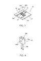
- FIG. 1 is a schematic perspective view for illustrating a lighting device for vehicle 1 according to the embodiment.
- FIG. 2 is a schematic perspective view of a main body unit 10.
- FIG. 3 is a schematic perspective view of a light emitting module 20.
- FIG. 4 is a schematic perspective view of a socket 30.
- the main body unit 10 As illustrated in FIG. 1 , in the lighting device for vehicle 1, the main body unit 10, the light emitting module 20, the socket 30, and a power feeding unit 40 are provided.
- the main body unit 10 is provided with an accommodation unit 11, a flange unit 12, and a fin 13.
- the accommodation unit 11 has a cylindrical shape and protrudes from one face of the flange unit 12. A concave portion 11a is provided in the accommodation unit 11.
- a substrate 21 is provided on a base of the concave portion 11a.
- a face of the substrate 21 on a side opposite to the side on which a light emitting unit 22 of the substrate 21 is provided comes into contact with the base of the concave portion 11a.
- a plurality of power feeding terminals 41 protrudes from the base of the concave portion 11a.
- the plurality of power feeding terminals 41 do not come into contact with the base of the concave portion 11a.
- a plurality of projecting portions 11b are provided on a side wall of the accommodation unit 11.
- the plurality of projecting portions 11b hold the lighting device for vehicle 1 to a lighting tool (not illustrated) in cooperation with an attaching member on the lighting tool side, when attaching the lighting device for vehicle 1 to the lighting tool, or the like, which is not illustrated.
- the flange unit 12 has a disc shape, the accommodation unit 11 is provided on one face thereof, and the fin 13 is provided on the other face.
- a plurality of the fins 13 are provided by protruding from a face of the flange unit 12.
- the plurality of fins 13 have plate shapes, and function as heat radiating fins.
- the main body unit 10 has a function of accommodating the light emitting module 20, and a function of radiating heat which is generated in the light emitting module 20 to the outside of the lighting device for vehicle 1.
- the accommodation unit 11, the flange unit 12, and the fin 13 using a material with high thermal conductivity in consideration of radiating heat to the outside.
- the accommodation unit 11 the flange unit 12, and the fin 13 using a resin with high thermal conductivity.
- the resin with high thermal conductivity is, for example, a resin which is obtained by mixing a fiber or particles formed of carbon with high thermal conductivity, aluminum oxide, or the like, into a resin such as polyethylene terephthalate (PET) and nylon.
- PET polyethylene terephthalate
- accommodation unit 11 it is also possible to separately form the accommodation unit 11, the flange unit 12, and the fin 13, and bond the units.
- the accommodation unit 11, the flange unit 12, and the fin 13 it is possible to form the units using the same material, or using different materials.
- the substrate 21, the light emitting unit 22, a control element 23, and a wiring pattern 24 are provided in the light emitting module 20.
- the substrate 21 is provided inside the accommodation unit 11 of the main body unit 10.
- the substrate 21 has a plate shape, and the wiring pattern 24 is provided on a surface thereof.
- the material or the structure of the substrate 21 is not particularly limited.
- the substrate 21 can be formed of a material which is obtained by covering the surface of a metal plate using an insulating material.
- the insulating material may be formed of an organic material, or an inorganic material.
- the substrate 21 When the heat amount of the light emitting unit 22 is large, it is preferable to form the substrate 21 using a material with high thermal conductivity in consideration of heat radiation.
- a material with high thermal conductivity for example, it is possible to exemplify ceramics such as aluminum oxide or aluminum nitride, a resin with high thermal conductivity, a material which is obtained by covering the surface of a metal plate with an insulating material, or the like.
- the substrate 21 may be a single layer substrate, or a multilayer substrate.
- the plurality of light emitting units 22 are mounted on the wiring pattern 24 which is provided on the surface of the substrate 21.
- a light emitting element 22a, an envelope 22b, lead 22c, and a sealing unit 22d are provided in the light emitting unit 22.
- the light emitting element 22a is provided inside a concave portion 22b1 which is provided in the envelope 22b.
- the light emitting element 22a is electrically connected to the lead 22c which is exposed to the inside of the concave portion 22b1.
- the light emitting element 22a can be made as, for example, a light emitting diode, an organic light emitting diode, a laser diode, or the like.
- a top face of the light emitting element 22a which is an emission face of light faces the front face side of the lighting device for vehicle 1, and mainly emits light toward the front face side of the lighting device for vehicle 1.
- the envelope 22b can be formed of, for example, a resin such as polybutylene terephthalate (PBT) or polycarbonate (PC), ceramics, or the like.
- a resin such as polybutylene terephthalate (PBT) or polycarbonate (PC), ceramics, or the like.
- a material of the envelope 22b is set to be a resin, it is possible to improve reflectance with respect to light which is emitted from the light emitting element 22a by mixing particles such as titanium oxide into the material.
- particles of titanium oxide and particles formed of a material having high reflectance with respect to light emitted from the light emitting element 22a may be mixed into the material.
- the envelope 22b it is possible to form the envelope 22b using a white resin, for example.
- a side wall face of the concave portion 22b1 of the envelope 22b is a slope. Part of the light which is emitted from the light emitting element 22a is reflected on the side wall face of the envelope 22b, and is emitted toward the front face side of the lighting device for vehicle 1.
- part of the light which is emitted toward the front face side of the lighting device for vehicle 1 from the light emitting element 22a, and is totally reflected on a top face (interface between sealing unit 22d and outside air) of the sealing unit 22d is reflected on the side wall face of the concave portion 22b1 of the envelope 22b, and is emitted toward the front face side of the lighting device for vehicle 1 again.
- the envelope 22b can also function as a reflector.
- the shape of the envelope 22b is not limited to the exemplification, and can be appropriately changed.
- One end portion side of the lead 22c is exposed to the inside of the concave portion 22b1 of the envelope 22b.
- the other end of the lead 22c is bent toward a face (base) on a side opposite to the side to which the concave portion 22b1 of the envelope 22b is open.
- the lead 22c can be a J bent-type lead.
- a portion of the lead 22c which is exposed to the inside of the concave portion 22b1 is electrically connected to the light emitting element 22a.
- a portion of the lead 22c which is bent toward the base of the envelope 22b is electrically connected to the wiring pattern 24.
- the light emitting element 22a is electrically connected to the wiring pattern 24 through the lead 22c.
- the sealing unit 22d is provided in the concave portion 22b1 of the envelope 22b.
- the sealing unit 22d is provided so as to cover the inside of the concave portion 22b1. That is, the sealing unit 22d is provided inside the concave portion 22b1, and covers the light emitting element 22a, and one end portion side of the lead 22c.
- the sealing unit 22d is formed of a material with light transmittance. It is possible to form the sealing unit 22d using, for example, a silicone resin, or the like.
- the sealing unit 22d by filling the concave portion 22b1 of the envelope 22b with a resin, for example. Filling of a resin can be performed using a quantitative liquid discharge device such as a dispenser, for example.
- the concave portion 22b1 of the envelope 22b is filled with a resin, it is possible to suppress mechanical contact from the outside with respect to the light emitting element 22a. In addition, it is possible to suppress attachment of gas, moisture, or the like, to the light emitting element 22a, or the like. For this reason, it is possible to improve the reliability of the lighting device for vehicle 1.
- the sealing unit 22d may contain a fluorescence substance.
- the fluorescence substance may be, for example, a YAG-type fluorescence substance (yttrium-aluminum-garnet fluorescence substance).
- the light emitting element 22a is a blue light emitting diode and the fluorescence substance is the YAG-type fluorescence substance
- the YAG-type fluorescence substance is excited due to blue light which is emitted from the light emitting element 22a, and yellow fluorescence is radiated from the YAG-type fluorescence substance.
- white light is emitted from the lighting device for vehicle 1 when the blue light and yellow light are mixed together.
- the type of the fluorescence substance or a type of the light emitting element 22a is not limited to the exemplification, and it is possible to appropriately change the type so as to obtain a desired color of the emitted light according to a use, or the like, of the lighting device for vehicle 1.
- the light emitting unit 22 which is illustrated in FIG. 3 is a Plastic Leaded Chip Carrier (PLCC) type; however, the form of the light emitting unit 22 is not limited to this.
- PLCC Plastic Leaded Chip Carrier
- the light emitting unit 22 may include the light emitting element 22a which is mounted on the wiring pattern, an annular reflector which surrounds the light emitting element 22a, and the sealing unit 22d which is provided inside the annular reflector.
- the light emitting element 22a may be mounted on the wiring pattern 24 using Chip on Board (COB).
- COB Chip on Board
- the number or arrangement of the light emitting unit 22 is not limited to the exemplification, and can be appropriately changed according to the use, or the like, of the lighting device for vehicle 1.
- the control element 23 is mounted on the wiring pattern 24.
- the control element 23 controls a current which flows in the light emitting element 22a. That is, the control element 23 controls the light emission of the light emitting element 22a.
- control element 23 is not limited to the exemplification, and can be appropriately changed according to the number, the specification, or the like, of the light emitting element 22a.
- the wiring pattern 24 is provided at least on one side of the surface of the substrate 21.
- the wiring pattern 24 is preferable to provide the wiring pattern 24 on the surface on one side of the substrate 21 in order to reduce a manufacturing cost, though it is also possible to provide the wiring pattern on both surfaces of the substrate 21.
- An input terminal 24a is provided in the wiring pattern 24.
- the input terminal 24a is provided in a plural manner.
- the power feeding terminal 41 is electrically connected to the input terminal 24a.
- the light emitting element 22a is electrically connected to the power feeding terminal 41 through the wiring pattern 24.
- circuit component or the like (not illustrated,) as necessary. It is possible to mount the circuit component (not illustrated) on the wiring pattern 24, for example.
- a main body unit 30a, a female type terminal 30b, and wiring 30c are provided in the socket 30.
- the main body unit 30a is formed of an insulating material such as a resin.
- a projecting portion 30a1 is provided on a side wall of the main body unit 30a.
- the socket 30 is held by the main body unit 10 when the projecting portion 30a1 is inserted into the concave portion which is provided in the main body unit 10.
- the female type terminal 30b stretches inside the main body unit 30a.
- One end portion of the female type terminal 30b is exposed to one end face of the main body unit 30a.
- the power feeding terminal 41 is fitted to an end portion of the female type terminal 30b which is exposed to one end face of the main body unit 30a.
- the wiring 30c is electrically connected to the other end of the female type terminal 30b.
- a power supply, or the like (not illustrated), is electrically connected to the wiring 30c.
- the socket 30 can be bonded to elements on the main body unit 10 side using, for example, an adhesive, or the like.
- FIG. 5 is a schematic sectional view for illustrating the power feeding unit 40.
- FIG. 5 is a diagram which illustrates a section including a line A-A in FIG. 1 .
- the power feeding terminal 41 and the holding unit 42 are provided in the power feeding unit 40.
- a plurality of the power feeding terminals 41 is provided.
- the power feeding terminal 41 has a linear shape, and is formed of a conductive material such as metal.
- the plurality of power feeding terminals 41 stretches by penetrating the holding unit 42.
- An end portion of the power feeding terminal 41 on the input terminal 24a side protrudes from an end portion 42a of the holding unit 42 on the input terminal 24a side.
- the power feeding terminal 41 which protrudes from the end portion 42a of the holding unit 42 protrudes from a base of the concave portion 11a, and is electrically connected to the input terminal 24a.
- An end portion of the power feeding terminal 41 on the socket 30 side protrudes from an end portion 42b of the holding unit 42 on the socket 30 side.
- the power feeding terminal 41 which protrudes from the end portion 42b of the holding unit 42 is fitted to the female type terminal 30b.
- Two power feeding terminals 41 are exemplified; however, the number, the shape, or the like, of the power feeding terminal 41 is not limited to the exemplification, and can be appropriately changed.
- the main body unit 10 it is preferable to form the main body unit 10 using a resin with high thermal conductivity.
- the resin with high thermal conductivity there is a resin with high thermal conductivity which is obtained by mixing a fiber or particles formed of carbon into a resin. For this reason, there is a resin with high thermal conductivity which has electrical conductivity.
- the holding unit 42 which is formed of an insulating material is provided between the main body unit 10 and the power feeding terminal 41.
- the holding unit 42 is provided inside a hole 10a which is provided in the main body unit 10.
- the hole 10a penetrates between an end portion 10b of the main body unit 10 (corresponding to an example of first end portion) on a side on which the light emitting module 20 is provided and an end portion 10c (corresponding to an example of second end portion) on a side on which the socket 30 is provided.
- the operating environment of the lighting device for vehicle 1 is -40°C to 85°C.
- the linear expansion coefficient of the resin with high thermal conductivity which is a material of the main body unit 10 and the linear expansion coefficient of a resin which is a material of the holding unit 42 are set so as to be as close to each other as possible. By doing so, it is possible to reduce thermal stress which occurs between the main body unit 10 and the holding unit 42, even when the lighting device for vehicle 1 is used in circumstances in which the change in temperature is significant.
- the holding unit 42 it is possible to form the holding unit 42 using a resin which belongs to the resin with high thermal conductivity.
- the resin with high thermal conductivity is obtained by mixing a fiber or particles formed of carbon into a PET, it is possible to form the holding unit 42 using PET.
- an end portion of the power feeding terminal 41 on the socket 30 side is exposed from the holding unit 42 so as to be fitted to the female type terminal 30b of the socket 30.
- the end portion 42b of the holding unit 42 on the socket 30 side protrudes from a peripheral edge of the hole 10a of the main body unit 10.
- the shortest distance (creepage distance) along the surface of the holding unit 42 is equal to or greater than 1 mm between the power feeding terminal 41 and the peripheral edge of the hole 10a, it is possible to secure enough insulation for the lighting device for vehicle 1.
- a concave portion 42b1 can be provided in the end portion 42b of the holding unit 42 on the socket 30 side.
- the holding unit 42 when attaching the holding unit 42 to the main body unit 10, the holding unit 42 is inserted from an end portion of the hole 10a on the light emitting module 20 side.
- the holding unit 42 in a tapered shape.
- the angle of tapering the holding unit 42 it is preferable to set the angle of tapering the holding unit 42 to 1° or more.
- the angle of tapering the holding unit 42 is set to 1° or more, it is possible to reduce the amount of dust which is generated when inserting the holding unit 42 into the hole 10a.
Landscapes
- Engineering & Computer Science (AREA)
- General Engineering & Computer Science (AREA)
- Physics & Mathematics (AREA)
- Microelectronics & Electronic Packaging (AREA)
- Optics & Photonics (AREA)
- Arrangement Of Elements, Cooling, Sealing, Or The Like Of Lighting Devices (AREA)
- Led Device Packages (AREA)
- Non-Portable Lighting Devices Or Systems Thereof (AREA)
Applications Claiming Priority (1)
| Application Number | Priority Date | Filing Date | Title |
|---|---|---|---|
| JP2014239580A JP6464697B2 (ja) | 2014-11-27 | 2014-11-27 | 車両用照明装置、および灯具 |
Publications (2)
| Publication Number | Publication Date |
|---|---|
| EP3026329A1 true EP3026329A1 (fr) | 2016-06-01 |
| EP3026329B1 EP3026329B1 (fr) | 2020-11-25 |
Family
ID=54325414
Family Applications (1)
| Application Number | Title | Priority Date | Filing Date |
|---|---|---|---|
| EP15189672.7A Active EP3026329B1 (fr) | 2014-11-27 | 2015-10-14 | Dispositif d'eclairage pour vehicule |
Country Status (4)
| Country | Link |
|---|---|
| US (1) | US10260703B2 (fr) |
| EP (1) | EP3026329B1 (fr) |
| JP (1) | JP6464697B2 (fr) |
| CN (1) | CN205090290U (fr) |
Cited By (1)
| Publication number | Priority date | Publication date | Assignee | Title |
|---|---|---|---|---|
| EP3309448A1 (fr) * | 2016-10-11 | 2018-04-18 | Toshiba Lighting & Technology Corporation | Dispositif d'éclairage pour véhicule, méthode de fabrication du dispositif d'éclairage pour véhicule et outil d'éclairage pour véhicule |
Families Citing this family (3)
| Publication number | Priority date | Publication date | Assignee | Title |
|---|---|---|---|---|
| CN107013867A (zh) * | 2017-06-01 | 2017-08-04 | 广州市日雄电子科技有限公司 | 一种汽车led前照灯 |
| JP6969328B2 (ja) * | 2017-11-30 | 2021-11-24 | 東芝ライテック株式会社 | 車両用照明装置、および車両用灯具 |
| JP7049120B2 (ja) * | 2018-01-19 | 2022-04-06 | 株式会社小糸製作所 | 灯具ユニット及び車両用灯具並びに灯具ユニット製造方法 |
Citations (5)
| Publication number | Priority date | Publication date | Assignee | Title |
|---|---|---|---|---|
| DE102009054620A1 (de) * | 2009-12-14 | 2011-06-16 | Robert Bosch Gmbh | Lichtmodul zum Einbau in ein Leuchtaggregat |
| EP2345836A2 (fr) * | 2010-01-19 | 2011-07-20 | Ichiko Industries, Ltd. | Unité de source de lumière pour une source de lumière de type semi-conductrice d'un dispositif d'éclairage de véhicule et dispositif d'éclairage de véhicule |
| EP2434206A2 (fr) * | 2010-09-28 | 2012-03-28 | Ichikoh Industries, Ltd. | Unité de source de lumière pour une source de lumière de type semi-conductrice d'un dispositif d'éclairage de véhicule et dispositif d'éclairage de véhicule |
| WO2013180178A1 (fr) * | 2012-05-29 | 2013-12-05 | 市光工業株式会社 | Unité source de lumière à semi-conducteurs pour instrument d'éclairage de véhicule et instrument d'éclairage de véhicule |
| JP2014212073A (ja) * | 2013-04-19 | 2014-11-13 | 東芝ライテック株式会社 | 照明装置 |
Family Cites Families (13)
| Publication number | Priority date | Publication date | Assignee | Title |
|---|---|---|---|---|
| JP3629811B2 (ja) * | 1996-05-08 | 2005-03-16 | 松下電器産業株式会社 | 接続端子付配線基板 |
| WO1998050943A1 (fr) * | 1997-05-06 | 1998-11-12 | Koninklijke Philips Electronics N.V. | Ampoule electrique a culot |
| WO2000074099A1 (fr) * | 1999-06-01 | 2000-12-07 | Koninklijke Philips Electronics N.V. | Ampoule electrique a calotte |
| KR100593919B1 (ko) * | 2004-07-01 | 2006-06-30 | 삼성전기주식회사 | 차량 전조등용 발광 다이오드 모듈 및 이를 구비한 차량전조등 |
| JP5038623B2 (ja) * | 2005-12-27 | 2012-10-03 | 株式会社東芝 | 光半導体装置およびその製造方法 |
| DE602007010110D1 (de) * | 2006-03-10 | 2010-12-09 | Koninkl Philips Electronics Nv | Automobillampe mit einer an der abdeckung der lampe montierten glühbirne |
| JP5272768B2 (ja) * | 2009-02-05 | 2013-08-28 | 三菱電機株式会社 | 電力用半導体装置とその製造方法 |
| JP2011091033A (ja) * | 2009-09-25 | 2011-05-06 | Toshiba Lighting & Technology Corp | 発光モジュール、電球形ランプおよび照明器具 |
| JP5879561B2 (ja) | 2011-11-22 | 2016-03-08 | パナソニックIpマネジメント株式会社 | 給電制御装置 |
| JP2014107229A (ja) * | 2012-11-29 | 2014-06-09 | Toshiba Lighting & Technology Corp | 発光装置および車両用照明装置 |
| JP6094202B2 (ja) | 2012-12-19 | 2017-03-15 | 市光工業株式会社 | 車両用灯具の半導体型光源の光源ユニット、車両用灯具 |
| US11166697B2 (en) * | 2013-03-29 | 2021-11-09 | Koninklijke Philips N.V. | Systems for measuring force and torque on ultrasound probe during imaging through strain measurement |
| US9165937B2 (en) * | 2013-07-01 | 2015-10-20 | Micron Technology, Inc. | Semiconductor devices including stair step structures, and related methods |
-
2014
- 2014-11-27 JP JP2014239580A patent/JP6464697B2/ja active Active
-
2015
- 2015-10-14 EP EP15189672.7A patent/EP3026329B1/fr active Active
- 2015-10-16 US US14/884,842 patent/US10260703B2/en active Active
- 2015-10-26 CN CN201520833138.XU patent/CN205090290U/zh active Active
Patent Citations (5)
| Publication number | Priority date | Publication date | Assignee | Title |
|---|---|---|---|---|
| DE102009054620A1 (de) * | 2009-12-14 | 2011-06-16 | Robert Bosch Gmbh | Lichtmodul zum Einbau in ein Leuchtaggregat |
| EP2345836A2 (fr) * | 2010-01-19 | 2011-07-20 | Ichiko Industries, Ltd. | Unité de source de lumière pour une source de lumière de type semi-conductrice d'un dispositif d'éclairage de véhicule et dispositif d'éclairage de véhicule |
| EP2434206A2 (fr) * | 2010-09-28 | 2012-03-28 | Ichikoh Industries, Ltd. | Unité de source de lumière pour une source de lumière de type semi-conductrice d'un dispositif d'éclairage de véhicule et dispositif d'éclairage de véhicule |
| WO2013180178A1 (fr) * | 2012-05-29 | 2013-12-05 | 市光工業株式会社 | Unité source de lumière à semi-conducteurs pour instrument d'éclairage de véhicule et instrument d'éclairage de véhicule |
| JP2014212073A (ja) * | 2013-04-19 | 2014-11-13 | 東芝ライテック株式会社 | 照明装置 |
Cited By (2)
| Publication number | Priority date | Publication date | Assignee | Title |
|---|---|---|---|---|
| EP3309448A1 (fr) * | 2016-10-11 | 2018-04-18 | Toshiba Lighting & Technology Corporation | Dispositif d'éclairage pour véhicule, méthode de fabrication du dispositif d'éclairage pour véhicule et outil d'éclairage pour véhicule |
| US10371366B2 (en) | 2016-10-11 | 2019-08-06 | Toshiba Lighting & Technology Corporation | Lighting device for vehicle, manufacturing method of lighting device for vehicle, and lighting tool for vehicle |
Also Published As
| Publication number | Publication date |
|---|---|
| JP6464697B2 (ja) | 2019-02-06 |
| US10260703B2 (en) | 2019-04-16 |
| JP2016103315A (ja) | 2016-06-02 |
| EP3026329B1 (fr) | 2020-11-25 |
| CN205090290U (zh) | 2016-03-16 |
| US20160153636A1 (en) | 2016-06-02 |
Similar Documents
| Publication | Publication Date | Title |
|---|---|---|
| EP2256402A1 (fr) | Lampe à élément électroluminescent et luminaire | |
| US10327304B2 (en) | Light emitting device for vehicle, lighting device for vehicle, and lighting tool for vehicle | |
| US10023108B2 (en) | Vehicle lamp with light module fixing portion | |
| US9625142B2 (en) | Luminaire | |
| US10371340B2 (en) | Vehicle lighting device and vehicle lamp | |
| EP2762773A1 (fr) | Dispositif d'éclairage et luminaire | |
| EP3026329B1 (fr) | Dispositif d'eclairage pour vehicule | |
| EP3537033B1 (fr) | Luminaire de véhicule, phare de véhicule et procédé de fabrication d'un luminaire de véhicule | |
| JP7157915B2 (ja) | 車両用照明装置および車両用灯具 | |
| JP6160858B2 (ja) | 照明装置および灯具 | |
| JP2014203575A (ja) | 照明装置 | |
| US9620690B2 (en) | Lighting system | |
| JP6394959B2 (ja) | 照明装置の製造方法 | |
| JP6217962B2 (ja) | 車両用照明装置、および車両用灯具 | |
| JP2016106355A (ja) | 車両用照明装置、及びその製造方法 | |
| JP6447811B2 (ja) | 灯具 | |
| JP7091855B2 (ja) | 車両用照明装置、および車両用灯具 | |
| JP7075050B2 (ja) | 車両用照明装置、および車両用灯具 | |
| JP6179761B2 (ja) | 照明装置および灯具 |
Legal Events
| Date | Code | Title | Description |
|---|---|---|---|
| PUAI | Public reference made under article 153(3) epc to a published international application that has entered the european phase |
Free format text: ORIGINAL CODE: 0009012 |
|
| AK | Designated contracting states |
Kind code of ref document: A1 Designated state(s): AL AT BE BG CH CY CZ DE DK EE ES FI FR GB GR HR HU IE IS IT LI LT LU LV MC MK MT NL NO PL PT RO RS SE SI SK SM TR |
|
| AX | Request for extension of the european patent |
Extension state: BA ME |
|
| STAA | Information on the status of an ep patent application or granted ep patent |
Free format text: STATUS: REQUEST FOR EXAMINATION WAS MADE |
|
| 17P | Request for examination filed |
Effective date: 20161128 |
|
| RBV | Designated contracting states (corrected) |
Designated state(s): AL AT BE BG CH CY CZ DE DK EE ES FI FR GB GR HR HU IE IS IT LI LT LU LV MC MK MT NL NO PL PT RO RS SE SI SK SM TR |
|
| STAA | Information on the status of an ep patent application or granted ep patent |
Free format text: STATUS: EXAMINATION IS IN PROGRESS |
|
| 17Q | First examination report despatched |
Effective date: 20200330 |
|
| REG | Reference to a national code |
Ref country code: DE Ref legal event code: R079 Ref document number: 602015062445 Country of ref document: DE Free format text: PREVIOUS MAIN CLASS: F21S0008100000 Ipc: F21S0041190000 |
|
| GRAP | Despatch of communication of intention to grant a patent |
Free format text: ORIGINAL CODE: EPIDOSNIGR1 |
|
| STAA | Information on the status of an ep patent application or granted ep patent |
Free format text: STATUS: GRANT OF PATENT IS INTENDED |
|
| RIC1 | Information provided on ipc code assigned before grant |
Ipc: F21S 45/10 20180101ALI20200604BHEP Ipc: F21S 41/141 20180101ALI20200604BHEP Ipc: F21S 41/19 20180101AFI20200604BHEP Ipc: F21S 43/14 20180101ALI20200604BHEP Ipc: F21S 45/48 20180101ALI20200604BHEP Ipc: F21S 43/19 20180101ALI20200604BHEP |
|
| INTG | Intention to grant announced |
Effective date: 20200629 |
|
| GRAS | Grant fee paid |
Free format text: ORIGINAL CODE: EPIDOSNIGR3 |
|
| GRAA | (expected) grant |
Free format text: ORIGINAL CODE: 0009210 |
|
| STAA | Information on the status of an ep patent application or granted ep patent |
Free format text: STATUS: THE PATENT HAS BEEN GRANTED |
|
| AK | Designated contracting states |
Kind code of ref document: B1 Designated state(s): AL AT BE BG CH CY CZ DE DK EE ES FI FR GB GR HR HU IE IS IT LI LT LU LV MC MK MT NL NO PL PT RO RS SE SI SK SM TR |
|
| REG | Reference to a national code |
Ref country code: GB Ref legal event code: FG4D |
|
| REG | Reference to a national code |
Ref country code: CH Ref legal event code: EP |
|
| REG | Reference to a national code |
Ref country code: AT Ref legal event code: REF Ref document number: 1338751 Country of ref document: AT Kind code of ref document: T Effective date: 20201215 |
|
| REG | Reference to a national code |
Ref country code: DE Ref legal event code: R096 Ref document number: 602015062445 Country of ref document: DE |
|
| REG | Reference to a national code |
Ref country code: IE Ref legal event code: FG4D |
|
| REG | Reference to a national code |
Ref country code: AT Ref legal event code: MK05 Ref document number: 1338751 Country of ref document: AT Kind code of ref document: T Effective date: 20201125 |
|
| REG | Reference to a national code |
Ref country code: NL Ref legal event code: MP Effective date: 20201125 |
|
| PG25 | Lapsed in a contracting state [announced via postgrant information from national office to epo] |
Ref country code: RS Free format text: LAPSE BECAUSE OF FAILURE TO SUBMIT A TRANSLATION OF THE DESCRIPTION OR TO PAY THE FEE WITHIN THE PRESCRIBED TIME-LIMIT Effective date: 20201125 Ref country code: FI Free format text: LAPSE BECAUSE OF FAILURE TO SUBMIT A TRANSLATION OF THE DESCRIPTION OR TO PAY THE FEE WITHIN THE PRESCRIBED TIME-LIMIT Effective date: 20201125 Ref country code: PT Free format text: LAPSE BECAUSE OF FAILURE TO SUBMIT A TRANSLATION OF THE DESCRIPTION OR TO PAY THE FEE WITHIN THE PRESCRIBED TIME-LIMIT Effective date: 20210325 Ref country code: NO Free format text: LAPSE BECAUSE OF FAILURE TO SUBMIT A TRANSLATION OF THE DESCRIPTION OR TO PAY THE FEE WITHIN THE PRESCRIBED TIME-LIMIT Effective date: 20210225 Ref country code: GR Free format text: LAPSE BECAUSE OF FAILURE TO SUBMIT A TRANSLATION OF THE DESCRIPTION OR TO PAY THE FEE WITHIN THE PRESCRIBED TIME-LIMIT Effective date: 20210226 |
|
| PG25 | Lapsed in a contracting state [announced via postgrant information from national office to epo] |
Ref country code: BG Free format text: LAPSE BECAUSE OF FAILURE TO SUBMIT A TRANSLATION OF THE DESCRIPTION OR TO PAY THE FEE WITHIN THE PRESCRIBED TIME-LIMIT Effective date: 20210225 Ref country code: AT Free format text: LAPSE BECAUSE OF FAILURE TO SUBMIT A TRANSLATION OF THE DESCRIPTION OR TO PAY THE FEE WITHIN THE PRESCRIBED TIME-LIMIT Effective date: 20201125 Ref country code: PL Free format text: LAPSE BECAUSE OF FAILURE TO SUBMIT A TRANSLATION OF THE DESCRIPTION OR TO PAY THE FEE WITHIN THE PRESCRIBED TIME-LIMIT Effective date: 20201125 Ref country code: LV Free format text: LAPSE BECAUSE OF FAILURE TO SUBMIT A TRANSLATION OF THE DESCRIPTION OR TO PAY THE FEE WITHIN THE PRESCRIBED TIME-LIMIT Effective date: 20201125 Ref country code: IS Free format text: LAPSE BECAUSE OF FAILURE TO SUBMIT A TRANSLATION OF THE DESCRIPTION OR TO PAY THE FEE WITHIN THE PRESCRIBED TIME-LIMIT Effective date: 20210325 Ref country code: SE Free format text: LAPSE BECAUSE OF FAILURE TO SUBMIT A TRANSLATION OF THE DESCRIPTION OR TO PAY THE FEE WITHIN THE PRESCRIBED TIME-LIMIT Effective date: 20201125 |
|
| REG | Reference to a national code |
Ref country code: LT Ref legal event code: MG9D |
|
| PG25 | Lapsed in a contracting state [announced via postgrant information from national office to epo] |
Ref country code: HR Free format text: LAPSE BECAUSE OF FAILURE TO SUBMIT A TRANSLATION OF THE DESCRIPTION OR TO PAY THE FEE WITHIN THE PRESCRIBED TIME-LIMIT Effective date: 20201125 |
|
| PG25 | Lapsed in a contracting state [announced via postgrant information from national office to epo] |
Ref country code: EE Free format text: LAPSE BECAUSE OF FAILURE TO SUBMIT A TRANSLATION OF THE DESCRIPTION OR TO PAY THE FEE WITHIN THE PRESCRIBED TIME-LIMIT Effective date: 20201125 Ref country code: CZ Free format text: LAPSE BECAUSE OF FAILURE TO SUBMIT A TRANSLATION OF THE DESCRIPTION OR TO PAY THE FEE WITHIN THE PRESCRIBED TIME-LIMIT Effective date: 20201125 Ref country code: SM Free format text: LAPSE BECAUSE OF FAILURE TO SUBMIT A TRANSLATION OF THE DESCRIPTION OR TO PAY THE FEE WITHIN THE PRESCRIBED TIME-LIMIT Effective date: 20201125 Ref country code: LT Free format text: LAPSE BECAUSE OF FAILURE TO SUBMIT A TRANSLATION OF THE DESCRIPTION OR TO PAY THE FEE WITHIN THE PRESCRIBED TIME-LIMIT Effective date: 20201125 Ref country code: RO Free format text: LAPSE BECAUSE OF FAILURE TO SUBMIT A TRANSLATION OF THE DESCRIPTION OR TO PAY THE FEE WITHIN THE PRESCRIBED TIME-LIMIT Effective date: 20201125 Ref country code: SK Free format text: LAPSE BECAUSE OF FAILURE TO SUBMIT A TRANSLATION OF THE DESCRIPTION OR TO PAY THE FEE WITHIN THE PRESCRIBED TIME-LIMIT Effective date: 20201125 |
|
| REG | Reference to a national code |
Ref country code: DE Ref legal event code: R097 Ref document number: 602015062445 Country of ref document: DE |
|
| PG25 | Lapsed in a contracting state [announced via postgrant information from national office to epo] |
Ref country code: DK Free format text: LAPSE BECAUSE OF FAILURE TO SUBMIT A TRANSLATION OF THE DESCRIPTION OR TO PAY THE FEE WITHIN THE PRESCRIBED TIME-LIMIT Effective date: 20201125 |
|
| PLBE | No opposition filed within time limit |
Free format text: ORIGINAL CODE: 0009261 |
|
| STAA | Information on the status of an ep patent application or granted ep patent |
Free format text: STATUS: NO OPPOSITION FILED WITHIN TIME LIMIT |
|
| PG25 | Lapsed in a contracting state [announced via postgrant information from national office to epo] |
Ref country code: AL Free format text: LAPSE BECAUSE OF FAILURE TO SUBMIT A TRANSLATION OF THE DESCRIPTION OR TO PAY THE FEE WITHIN THE PRESCRIBED TIME-LIMIT Effective date: 20201125 Ref country code: IT Free format text: LAPSE BECAUSE OF FAILURE TO SUBMIT A TRANSLATION OF THE DESCRIPTION OR TO PAY THE FEE WITHIN THE PRESCRIBED TIME-LIMIT Effective date: 20201125 Ref country code: NL Free format text: LAPSE BECAUSE OF FAILURE TO SUBMIT A TRANSLATION OF THE DESCRIPTION OR TO PAY THE FEE WITHIN THE PRESCRIBED TIME-LIMIT Effective date: 20201125 |
|
| 26N | No opposition filed |
Effective date: 20210826 |
|
| PG25 | Lapsed in a contracting state [announced via postgrant information from national office to epo] |
Ref country code: SI Free format text: LAPSE BECAUSE OF FAILURE TO SUBMIT A TRANSLATION OF THE DESCRIPTION OR TO PAY THE FEE WITHIN THE PRESCRIBED TIME-LIMIT Effective date: 20201125 Ref country code: ES Free format text: LAPSE BECAUSE OF FAILURE TO SUBMIT A TRANSLATION OF THE DESCRIPTION OR TO PAY THE FEE WITHIN THE PRESCRIBED TIME-LIMIT Effective date: 20201125 |
|
| REG | Reference to a national code |
Ref country code: CH Ref legal event code: PL |
|
| PG25 | Lapsed in a contracting state [announced via postgrant information from national office to epo] |
Ref country code: IS Free format text: LAPSE BECAUSE OF FAILURE TO SUBMIT A TRANSLATION OF THE DESCRIPTION OR TO PAY THE FEE WITHIN THE PRESCRIBED TIME-LIMIT Effective date: 20210325 |
|
| REG | Reference to a national code |
Ref country code: BE Ref legal event code: MM Effective date: 20211031 |
|
| GBPC | Gb: european patent ceased through non-payment of renewal fee |
Effective date: 20211014 |
|
| PG25 | Lapsed in a contracting state [announced via postgrant information from national office to epo] |
Ref country code: MC Free format text: LAPSE BECAUSE OF FAILURE TO SUBMIT A TRANSLATION OF THE DESCRIPTION OR TO PAY THE FEE WITHIN THE PRESCRIBED TIME-LIMIT Effective date: 20201125 |
|
| PG25 | Lapsed in a contracting state [announced via postgrant information from national office to epo] |
Ref country code: LU Free format text: LAPSE BECAUSE OF NON-PAYMENT OF DUE FEES Effective date: 20211014 Ref country code: GB Free format text: LAPSE BECAUSE OF NON-PAYMENT OF DUE FEES Effective date: 20211014 Ref country code: BE Free format text: LAPSE BECAUSE OF NON-PAYMENT OF DUE FEES Effective date: 20211031 |
|
| PG25 | Lapsed in a contracting state [announced via postgrant information from national office to epo] |
Ref country code: LI Free format text: LAPSE BECAUSE OF NON-PAYMENT OF DUE FEES Effective date: 20211031 Ref country code: CH Free format text: LAPSE BECAUSE OF NON-PAYMENT OF DUE FEES Effective date: 20211031 |
|
| PG25 | Lapsed in a contracting state [announced via postgrant information from national office to epo] |
Ref country code: IE Free format text: LAPSE BECAUSE OF NON-PAYMENT OF DUE FEES Effective date: 20211014 |
|
| PG25 | Lapsed in a contracting state [announced via postgrant information from national office to epo] |
Ref country code: HU Free format text: LAPSE BECAUSE OF FAILURE TO SUBMIT A TRANSLATION OF THE DESCRIPTION OR TO PAY THE FEE WITHIN THE PRESCRIBED TIME-LIMIT; INVALID AB INITIO Effective date: 20151014 |
|
| PG25 | Lapsed in a contracting state [announced via postgrant information from national office to epo] |
Ref country code: CY Free format text: LAPSE BECAUSE OF FAILURE TO SUBMIT A TRANSLATION OF THE DESCRIPTION OR TO PAY THE FEE WITHIN THE PRESCRIBED TIME-LIMIT Effective date: 20201125 |
|
| PGFP | Annual fee paid to national office [announced via postgrant information from national office to epo] |
Ref country code: FR Payment date: 20230905 Year of fee payment: 9 |
|
| PGFP | Annual fee paid to national office [announced via postgrant information from national office to epo] |
Ref country code: DE Payment date: 20230905 Year of fee payment: 9 |
|
| PG25 | Lapsed in a contracting state [announced via postgrant information from national office to epo] |
Ref country code: MK Free format text: LAPSE BECAUSE OF FAILURE TO SUBMIT A TRANSLATION OF THE DESCRIPTION OR TO PAY THE FEE WITHIN THE PRESCRIBED TIME-LIMIT Effective date: 20201125 |