EP3025417B1 - Elektrische maschine - Google Patents
Elektrische maschine Download PDFInfo
- Publication number
- EP3025417B1 EP3025417B1 EP14731966.9A EP14731966A EP3025417B1 EP 3025417 B1 EP3025417 B1 EP 3025417B1 EP 14731966 A EP14731966 A EP 14731966A EP 3025417 B1 EP3025417 B1 EP 3025417B1
- Authority
- EP
- European Patent Office
- Prior art keywords
- cable
- cable bushing
- electrical machine
- trough
- stator
- Prior art date
- Legal status (The legal status is an assumption and is not a legal conclusion. Google has not performed a legal analysis and makes no representation as to the accuracy of the status listed.)
- Not-in-force
Links
- 239000004020 conductor Substances 0.000 claims description 31
- 238000005266 casting Methods 0.000 claims description 22
- 239000000463 material Substances 0.000 claims description 18
- 238000002844 melting Methods 0.000 claims description 3
- 230000008018 melting Effects 0.000 claims description 3
- 238000004804 winding Methods 0.000 claims description 2
- 238000004382 potting Methods 0.000 description 8
- 238000009434 installation Methods 0.000 description 6
- 238000003780 insertion Methods 0.000 description 4
- 230000037431 insertion Effects 0.000 description 4
- 230000005288 electromagnetic effect Effects 0.000 description 3
- 238000003475 lamination Methods 0.000 description 2
- RYGMFSIKBFXOCR-UHFFFAOYSA-N Copper Chemical compound [Cu] RYGMFSIKBFXOCR-UHFFFAOYSA-N 0.000 description 1
- XAGFODPZIPBFFR-UHFFFAOYSA-N aluminium Chemical compound [Al] XAGFODPZIPBFFR-UHFFFAOYSA-N 0.000 description 1
- 229910052782 aluminium Inorganic materials 0.000 description 1
- 239000000919 ceramic Substances 0.000 description 1
- 238000001816 cooling Methods 0.000 description 1
- 229910052802 copper Inorganic materials 0.000 description 1
- 239000010949 copper Substances 0.000 description 1
- 238000005538 encapsulation Methods 0.000 description 1
- 239000012212 insulator Substances 0.000 description 1
- XLYOFNOQVPJJNP-UHFFFAOYSA-N water Substances O XLYOFNOQVPJJNP-UHFFFAOYSA-N 0.000 description 1
Images


Classifications
-
- H—ELECTRICITY
- H02—GENERATION; CONVERSION OR DISTRIBUTION OF ELECTRIC POWER
- H02K—DYNAMO-ELECTRIC MACHINES
- H02K3/00—Details of windings
- H02K3/32—Windings characterised by the shape, form or construction of the insulation
- H02K3/38—Windings characterised by the shape, form or construction of the insulation around winding heads, equalising connectors, or connections thereto
-
- H—ELECTRICITY
- H02—GENERATION; CONVERSION OR DISTRIBUTION OF ELECTRIC POWER
- H02K—DYNAMO-ELECTRIC MACHINES
- H02K3/00—Details of windings
- H02K3/46—Fastening of windings on the stator or rotor structure
- H02K3/52—Fastening salient pole windings or connections thereto
- H02K3/521—Fastening salient pole windings or connections thereto applicable to stators only
- H02K3/522—Fastening salient pole windings or connections thereto applicable to stators only for generally annular cores with salient poles
-
- H—ELECTRICITY
- H02—GENERATION; CONVERSION OR DISTRIBUTION OF ELECTRIC POWER
- H02K—DYNAMO-ELECTRIC MACHINES
- H02K5/00—Casings; Enclosures; Supports
- H02K5/04—Casings or enclosures characterised by the shape, form or construction thereof
- H02K5/22—Auxiliary parts of casings not covered by groups H02K5/06-H02K5/20, e.g. shaped to form connection boxes or terminal boxes
- H02K5/225—Terminal boxes or connection arrangements
-
- H—ELECTRICITY
- H02—GENERATION; CONVERSION OR DISTRIBUTION OF ELECTRIC POWER
- H02K—DYNAMO-ELECTRIC MACHINES
- H02K2203/00—Specific aspects not provided for in the other groups of this subclass relating to the windings
- H02K2203/09—Machines characterised by wiring elements other than wires, e.g. bus rings, for connecting the winding terminations
Definitions
- the invention relates to an electrical machine according to the preamble of patent claim 1.
- Such an electric machine is used inter alia in motor vehicles and is of the generic type EP 2 139 094 A1 known.
- the current development of electric machines leads to ever more complex and compact designs. Therefore, more and more sensors, such as temperature sensors and magnetic sensors, and also new modules are integrated, for example, an actuator for a friction clutch.
- sensors such as temperature sensors and magnetic sensors
- new modules are integrated, for example, an actuator for a friction clutch.
- a generic electric machine in which the casting material has a cable feedthrough structure in the form of a free space, which forms a passage through the casting material, wherein a cable feedthrough element forms the cable feedthrough structure.
- An electric machine designed in this way enables a space-saving arrangement of cables, lines and hoses within the electrical machine.
- the specially created free space which in a normal potting not allows passage and placement of cables, conduits or hoses within the grommet structure.
- the position of the cable feedthrough structure in the circumferential direction on the stator is freely selectable as required, for example, far enough away from a power connection of the connecting conductors in order to reduce electromagnetic effects as much as possible.
- the electrical machine shown is space-saving in comparison with other solutions.
- the cable feedthrough element is arranged on or within the interconnection region of the conductor carrier element and, after casting, forms the free space of the cable feedthrough structure. As a result, a simple, reproducible and uniform generation of the cable feedthrough structure is possible.
- an electrical cable is arranged.
- hoses for example for water cooling
- the cable feed-through structure it is also conceivable to arrange hoses, for example for water cooling, in the cable feed-through structure.
- hoses for example for water cooling
- only a part of the cable or hose cross section can be arranged within the recess of the cable feedthrough structure, in particular the trough.
- cable is used in the following for the purposes of pipe and hose.
- the cable feedthrough structure is arranged on a casting surface, which lies opposite the connecting conductors.
- the cable does not have to be pulled into the cable feed-through structure during assembly, but can be inserted laterally. This is advantageous, inter alia, if the cable is already connected or connected to the sensor or component provided for this purpose before the arrangement or positioning within the cable feedthrough structure. This makes a simple installation possible.
- the cable feedthrough structure is trough-shaped, ie form with an open or at least partially open side.
- a tab is arranged on the cable feedthrough element which protrudes into the free space.
- the tab allows a fixed positioning of the cable within the cable feedthrough structure, at least during assembly.
- a retaining device is arranged on the cable feedthrough element, particularly preferably on the tab.
- This retaining fuse may for example be designed as a retaining rib, which advantageously points to the interior of the cable feedthrough element.
- This retaining rib allows fixing of the cable or the hose within the cable feedthrough element. Fixing reliably prevents the cable from being able to pop out of or fall out of the cable feedthrough structure during assembly or operation. This fixation is particularly advantageous during assembly, since a dropped or spiked cable, which is not located at the desired position within or on the cable feedthrough structure, can be sheared or damaged by the attachment of other components.
- the cable feedthrough element is fixed to the conductor carrier element.
- a possible attachment can be done by a clamping of the cable feedthrough element between two walls of the conductor carrier element, but there are also other mounting options conceivable, such as stick or fix with a clip. It has proved to be advantageous if the conductor carrier element corresponding receptacles into which the cable feedthrough element is inserted, and recesses through which the cable is guided, has. The position of the cable feedthrough element is thus determined during the introduction of the potting material and also thereafter. One Determining the position of the cable feedthrough element is not necessarily necessary.
- the cable feedthrough element is positioned at the predetermined location during the introduction of the potting material, for example with a holding arm, then it is fixed by the potting. If the cable feedthrough element is arranged on the casting surface, there is the possibility that this example will be released by vibrations, which is why it also makes sense, for example, to arrange at least one further component in such a way that the cable feedthrough element is additionally fixed at its predetermined position.
- mounting portions are arranged laterally on the cable feedthrough element, wherein the mounting portions facing away from the free space.
- the mounting portions are substantially parallel to each other and lie substantially on a plane that is in turn substantially parallel to and aligned with the casting surface.
- the mounting portions together with the tab form a large bearing surface to facilitate the positioning and the insertion or insertion of the cable feedthrough element into the conductor carrier element.
- Another arrangement of the mounting sections and another combination of the mounting sections and the tab is quite conceivable.
- the mounting portions are shaped so that they engage in correspondingly shaped recesses of the conductor carrier element, so that only a correct installation position of the cable feedthrough element is possible. This is advantageous, inter alia, when other components engage in the cable feedthrough element and thus the installation position is predetermined.
- the cable feedthrough element is made of a material which is dimensionally stable at least up to the melting temperature of the casting material. As a result, deformations or damage to the cable feedthrough element during and after the introduction of the potting material are excluded.
- the cable feedthrough element can be designed as a plastic part.
- the cable feedthrough element in an electromagnetic shielding manner.
- the cable feedthrough element is metallic, e.g. made of copper or aluminum. This minimizes electromagnetic effects that occur between the interconnecting conductors and the cable being carried. Since it is not desirable to employ bare conductive components within the interconnect, a metallic cable feedthrough element may be provided with an insulating layer, e.g. plastic or ceramic, be coated.
- FIG. 1 an electric machine 4 is shown in external rotor type with a stator 10 and a rotor 6 only schematically indicated here.
- the invention can also be integrated in electrical machines of other embodiments, such as internal rotor machines.
- the stator 10 has a stator support 12, on which a stator lamination stack 14 is arranged.
- the laminated stator core 14 has a yoke region 16 and a plurality of stator teeth 18 (not visible, but the arrangement on the stator is indicated), which are arranged radially on the outside and uniformly distributed on the yoke region 16.
- the stator 10 on insulating body 20, each of a stator coil 22nd are wrapped, wherein the combination of an insulating body 20 and a stator coil 22 is a coil package.
- the insulating body 20 may be embodied inter alia in several parts.
- a coil package is disposed on each of the stator teeth 18.
- connection device 24 within which the stator coils 22 are connected in a connection region 25 via connecting conductor 26 to a power electronics 28.
- the connecting conductors 26 are embedded in a conductor carrier element 30, which serves inter alia as a casting mold for a casting 32.
- cover plate 8 (partially shown) is arranged, which covers the stator 10 and closes so that the smallest possible axial width of the electric machine is achieved.
- the encapsulation 32 has a cable feedthrough structure 34 in the form of a free space, to which recesses 36 of the conductor carrier element 30 are assigned.
- the cable feed-through structure 34 and the recesses 36 form a connection 38 between an inner space 40 and a radially arranged outer space 42 of the stator.
- This connection 38 can be used inter alia to lead cables, lines or hoses 44 in the interior 40 of the stator 10.
- the cable feedthrough structure 34 is disposed on the casting surface facing the connecting conductors 26.
- the cable feedthrough structure 34 is trough-shaped in this variant, in particular semicircular, wherein inside the cable feedthrough structure 34 electrical cables and lines 44 are arranged.
- the cable feed-through structure 34 is designed as a cable feed-through element 60.
- This cable feedthrough element 60 is arranged or fixed on the conductor carrier element 30 and partially enclosed by casting material. This is advantageous because the cable feedthrough structure 34 is uniformly reproducible independently of the potting 32.
- the cable feed-through element 60 is inter alia clamped between side walls 48, 50 of the conductor carrier element 30, which are sufficiently tilted inwards towards the connection region 25.
- the cable feedthrough element 60 has a main body 62, in this case trough-shaped, in particular semicircular. On this main body 62 further, advantageous for this application elements are arranged in the following, shown in the Fig. 2 and 3a - d It depends on the specific application, which of these embodiments are advantageous.
- a tab 64 is arranged, which projects into the free space of the cable feedthrough element. This tab 64 is used, inter alia, as a cover, behind which the cable 44 is inserted protected.
- a holding safety device in the form of a holding rib 66 is arranged on the lug 64, which points to the main body 62 and holds a cable 44 arranged in the cable feedthrough structure 34 between the base body 62, lug 64 and holding rib 66.
- a positioned cable 44 is fixed within the cable feedthrough element 60. This is particularly advantageous in assembly, since a once positioned cable 44 remains at the predetermined location and can no longer be sheared off or damaged by the attachment of further elements, for example the cover plate.
- mounting portions 68 are arranged, which point away from the base body 64.
- the mounting portions 68 are arranged substantially parallel to each other and substantially parallel to the tab 64 to produce a large bearing surface.
- This support surface allows easy insertion into suitable receptacles 46 of the conductor support element 30.
- the support surface, consisting of tab 64 and mounting portions 68 is arranged substantially parallel to and on the casting surface.
- mounting portions 68 are formed only over part of the length of the cable feedthrough element 60.
- the corresponding executed recordings 46 of the conductor support member 30, shown in FIG Fig. 4 set in combination with the execution of the mounting portions 68 a clear installation direction.
- An installation direction can be predetermined, inter alia, if the tab 64 is formed only over part of the cable feedthrough element 60. This is the case, inter alia, when a component, for example an arm 52 of a temperature sensor holder 54, partially engages in the cable feed-through element 60 in order to take over and continue the cable 44.
- the contact region lying inside in the installed state is bevelled by an angle ⁇ for easy insertion of the cable feedthrough element 60 (FIG. Fig. 3c ).
- the cable feed-through element 60 is first set with the beveled edge on the fitting receptacle 46 of the conductor support member 30 during assembly and then pressed into the receptacle 46 of the opposite side.
- the contact region of the cable feed-through element 60 lying opposite the beveled contact region is adapted to the curvature of the conductor carrier element 30 (FIG. Fig. 3d ).
- the cable feed-through element 60 undergoes no deformation or damage during the introduction of the casting material, it is advantageous to use a material which is dimensionally stable even at the melting temperature of the casting material.
- the material may be the same as that used for the conductor support member 30.
- the cable feedthrough element 60 is designed as a plastic part.
- the cable feedthrough element 60 may alternatively be designed to be electromagnetic shielding. This reduces electromagnetic effects between the connection conductors 26 and the cables 44 disposed within the cable feed-through member 60.
Landscapes
- Engineering & Computer Science (AREA)
- Power Engineering (AREA)
- Motor Or Generator Frames (AREA)
- Insulation, Fastening Of Motor, Generator Windings (AREA)
- Installation Of Indoor Wiring (AREA)
Description
- Die Erfindung betrifft eine elektrische Maschine gemäß dem Oberbegriff des Patentanspruchs 1.
- Eine solche elektrische Maschine wird unter anderem in Kraftfahrzeugen verwendet und ist aus der gattungsgemäßen
EP 2 139 094 A1 bekannt. Die gegenwärtige Entwicklung elektrischer Maschinen führt zu immer komplexeren und kompakteren Bauweisen. Daher werden immer mehr Sensoren, beispielsweise Temperatursensoren und Magnetsensoren, und auch neue Baugruppen integriert, beispielsweise ein Aktuator für eine Reibkupplung. In dieser Hinsicht ergibt sich das Erfordernis die dafür notwendigen Kabel, Leitungen, Schläuche, etc. in elektrischen Maschinen platzsparend in den Gesamtaufbau zu integrieren, wobei eine besondere Schwierigkeit darin besteht diese von außen platzsparend in einen geschlossenen Aufnahmeraum innerhalb eines ringförmigen Stators einzuführen. - Weitere elektrische Maschinen sind in der
JP 2008 029 090 A FR 2805 675 A1 US 4 132 460 , derEP 1 677 404 A2 und derUS 2013 / 064697 A1 offenbart, wobei die DruckschriftEP 1 677 404 A2 als nächstliegender Stand der Technik angesehen wird und die Präambel des unabhängigen Anspruchs 1 offenbart. - Es stellt sich somit die Aufgabe, Kabel, Leitungen, Schläuche, etc. möglichst platzsparend in der elektrischen Maschine anzuordnen.
- Diese vorstehende Aufgabe wird mittels einer elektrischen Maschine gemäß dem unabhängigen Patentanspruch gelöst.
- Gemäß der Erfindung wird eine gattungsgemäße elektrische Maschine vorgeschlagen, bei der das Gussmaterial eine Kabeldurchführungsstruktur in Form eines Freiraums aufweist, der einen Durchgang durch das Gussmaterial darstellt, wobei ein Kabeldurchführungselement die Kabeldurchführungsstruktur ausbildet.
- Eine auf diese Weise ausgeführte elektrische Maschine ermöglicht eine platzsparende Anordnung von Kabeln, Leitungen und Schläuchen innerhalb der elektrischen Maschine. Der speziell geschaffene Freiraum, der bei einem normalen Verguss nicht vorhanden ist, ermöglicht ein Durchführen und Anordnen von Kabeln, Leitungen oder Schläuchen innerhalb der Kabeldurchführungsstruktur. Die Position der Kabeldurchführungsstruktur in Umfangsrichtung am Stator ist je nach Anforderung frei wählbar, beispielsweise weit genug entfernt von einem Leistungsanschluss der Verbindungsleiter, um elektromagnetische Effekte größtmöglich zu verringern. Die dargestellte elektrische Maschine ist im Vergleich mit anderen Lösungen bauraumsparend.
- Das Kabeldurchführungselement wird dabei an oder innerhalb des Verschaltungsbereichs des Leiterträgerelements angeordnet und bildet nach dem Vergießen den Freiraum der Kabeldurchführungsstruktur aus. Dadurch ist eine einfache, reproduzierbare und gleichmäßige Erzeugung der Kabeldurchführungsstruktur möglich.
- Innerhalb der Kabeldurchführungsstruktur ist ein elektrisches Kabel angeordnet.
- Es ist jedoch auch denkbar Schläuche, beispielsweise für eine Wasserkühlung, in der Kabeldurchführungsstruktur anzuordnen. Des Weiteren kann, bei Blickrichtung in eine Kabeldurchführungsrichtung, auch nur ein Teil des Kabel- bzw. Schlauchquerschnitts innerhalb der Vertiefung der Kabeldurchführungsstruktur, insbesondere der Wanne angeordnet sein.
- Sofern nicht anders erwähnt, wird im Folgenden der Begriff Kabel stellvertretend für Leitung und Schlauch verwendet.
- In einer vorteilhaften Ausführungsform ist die Kabeldurchführungsstruktur an einer Gussoberfläche angeordnet, die den Verbindungsleitern gegenüberliegt. Einer der Vorteile dieser Variante ist, dass das Kabel bei der Montage nicht in die Kabeldurchführungsstruktur eingezogen werden muss, sondern seitlich eingelegt werden kann. Dies ist unter anderem von Vorteil, wenn das Kabel bereits vor der Anordnung bzw. Positionierung innerhalb der Kabeldurchführungsstruktur an dem dafür vorgesehenen Sensor oder Bauteil angeschlossen bzw. mit diesem verbunden ist. Dadurch ist eine einfache Montage möglich.
- Mit Vorteil ist die Kabeldurchführungsstruktur wannenförmig, d.h. mit einer offenen bzw. zumindest teilweise offenen Seite auszubilden.
- Günstigerweise ist an dem Kabeldurchführungselement eine Lasche angeordnet, die in den Freiraum ragt. Bei einer Anordnung des Kabeldurchführungselements an der Vergussoberfläche ermöglicht die Lasche eine festgelegte Positionierung des Kabels innerhalb der Kabeldurchführungsstruktur, zumindest während der Montage.
- In einer Weiterbildung ist an dem Kabeldurchführungselement, besonders bevorzugt an der Lasche eine Haltesicherung angeordnet. Diese Haltesicherung kann beispielsweise als Halterippe ausgebildet sein, die vorteilhafterweise zum Innenraum des Kabeldurchführungselements hinweist. Diese Halterippe ermöglicht ein Fixieren des Kabels bzw. des Schlauchs innerhalb des Kabeldurchführungselements. Durch die Fixierung wird sicher vermieden, dass das Kabel während der Montage oder im Betrieb aus der Kabeldurchführungsstruktur herausspringen oder herausfallen kann. Diese Fixierung ist besonders während der Montage von Vorteil, da ein herausgefallenes bzw. herausgesprungenes Kabel, das nicht an der gewünschten Position innerhalb oder an der Kabeldurchführungsstruktur angeordnet ist, durch den Anbau weiterer Bauteile abgeschert oder beschädigt werden kann.
- Gemäß einer weiteren Ausführungsform hat es sich als vorteilhaft erwiesen, die Lasche nur über einen Teil des Kabeldurchführungselements auszubilden. Dies ist von Vorteil, wenn beispielsweise ein weiteres Bauteil einseitig und teilweise in den Bereich der Kabeldurchführungsstruktur eingreift, um das Kabel direkt an dem Kabeldurchführungselement aufzunehmen und weiterzuführen, beispielsweise mit einem Arm.
- In einer weiteren vorteilhaften Ausbildungsvariante ist das Kabeldurchführungselement an dem Leiterträgerelement festgelegt. Eine mögliche Befestigung kann durch eine Klemmung des Kabeldurchführungselements zwischen zwei Wänden des Leiterträgerelements geschehen, es sind jedoch auch andere Befestigungsmöglichkeiten denkbar, wie beispielsweise kleben oder fixieren mit einem Clip. Es hat sich als vorteilhaft erwiesen, wenn das Leiterträgerelement entsprechende Aufnahmen, in die das Kabeldurchführungselement eingesetzt ist, und Aussparungen, durch die das Kabel geführt wird, aufweist. Die Position des Kabeldurchführungselements ist damit während des Einbringens des Vergussmaterials und auch danach festgelegt. Ein Festlegen der Position des Kabeldurchführungselements ist nicht zwangsweise notwendig. Wird das Kabeldurchführungselement während dem Einbringen des Vergussmaterials an der vorbestimmten Stelle, beispielsweise mit einem Haltearm, positioniert, ist es danach durch den Verguss fixiert. Ist das Kabeldurchführungselement an der Gussoberfläche angeordnet, besteht die Möglichkeit, dass sich dieses beispielsweises durch Vibrationen löst, weshalb es z.B. auch aus Bauraumgründen sinnvoll erscheint, mindestens ein weiteres Bauteil so anzuordnen, dass das Kabeldurchführungselement an seiner vorgegebenen Position zusätzlich festgelegt ist.
- Vorteilhafterweise sind Montageabschnitte seitlich an dem Kabeldurchführungselement angeordnet, wobei die Montageabschnitte von dem Freiraum weg weisen. In bevorzugter Weise sind die Montageabschnitte im Wesentlichen parallel zueinander und liegen im Wesentlichen auf einer Ebene, die wiederum im Wesentlichen parallel zu und an der Gussoberfläche ausgerichtet ist. Die Montageabschnitte bilden gemeinsam mit der Lasche eine große Auflagefläche, um das Positionieren und das Eindrücken bzw. Einsetzen des Kabeldurchführungselements in das Leiterträgerelement zu erleichtern. Eine andere Anordnung der Montageabschnitte sowie eine andere Kombination der Montageabschnitten und der Lasche ist durchaus denkbar. Des Weiteren ist es vorteilhaft, wenn die Montageabschnitte so geformt sind, dass diese in entsprechend geformte Ausnehmungen des Leiterträgerelements eingreifen, damit nur eine korrekte Einbaulage des Kabeldurchführungselements möglich ist. Dies ist unter anderem dann von Vorteil, wenn andere Bauteile in das Kabeldurchführungselement eingreifen und dadurch die Einbaulage vorgegeben ist.
- Es hat sich als vorteilhaft herausgestellt, dass das Kabeldurchführungselement aus einem Material hergestellt ist, das mindestens bis zur Schmelztemperatur des Gussmaterials formstabil ist. Dadurch sind Deformationen oder Beschädigungen des Kabeldurchführungselements während und nach dem Einbringen des Vergussmaterials ausgeschlossen.
- Mit besonderem Vorteil kann das Kabeldurchführungselement als Kunststoffteil ausgeführt sein.
- Gemäß einer weiteren bevorzugten Ausbildungsvariante ist vorgesehen, das Kabeldurchführungselement elektromagnetisch abschirmend auszuführen. Dies kann beispielsweise erreicht werden, wenn das Kabeldurchführungselement metallisch, z.B. aus Kupfer oder Aluminium ausgeführt ist. Dadurch werden elektromagnetische Effekte, die zwischen den Verbindungsleitern und dem durchgeführten Kabel auftreten minimiert. Da es nicht wünschenswert ist, innerhalb der Verschaltungseinrichtung blanke, leitende Bauteile einzusetzen, kann ein metallisches Kabeldurchführungselement mit einer isolierenden Schicht, z.B. aus Kunststoff oder Keramik, überzogen sein.
- Nachfolgend wird die Erfindung anhand der beigefügten Figuren beispielhaft erläutert.
- Es zeigen:
- Fig. 1
- Stator einer elektrischen Maschine mit einer Kabeldurchführungsstruktur;
- Fig. 2
- Bildausschnitt des Stators aus
Fig. 1 mit einem Kabeldurchführungselement; - Fig. 3a - d
- ein Kabeldurchführungselement in verschiedenen Ansichten;
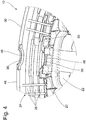
- Fig. 4
- Bildausschnitt des Stators aus
Fig. 1 mit Aussparungen eines Leiterträgerelements. - In
Fig. 1 ist eine elektrische Maschine 4 in Außenläuferbauart mit einem Stator 10 und einem hier nur schematisch angedeuteten Rotor 6 dargestellt. Die Erfindung lässt sich außerdem auch in elektrische Maschinen anderer Ausführungsarten integrieren, beispielsweise Maschinen in Innenläuferbauart. - Der Stator 10 weist einen Statorträger 12 auf, an dem ein Statorblechpaket 14 angeordnet ist. Das Statorblechpaket 14 weist einen Jochbereich 16 und mehrere Statorzähne 18 auf (nicht sichtbar, die Anordnung am Stator ist jedoch angedeutet), die radial außen und gleichmäßig verteilt am Jochbereich 16 angeordnet sind. Des Weiteren weist der Stator 10 Isolierkörper 20 auf, die jeweils von einer Statorspule 22 umwickelt sind, wobei die Kombination eines Isolierkörpers 20 und einer Statorspule 22 ein Spulenpaket darstellt. Der Isolierkörper 20 kann unter anderem mehrteilig ausgeführt sein. Ein Spulenpaket ist jeweils an einem der Statorzähne 18 angeordnet. Die Wicklungsenden der Statorspulen 22 sind in eine Verschaltungseinrichtung 24 geführt, innerhalb derer die Statorspulen 22 in einem Verschaltungsbereich 25 über Verbindungsleiter 26 mit einer Leistungselektronik 28 verschaltet sind. Die Verbindungsleiter 26 sind in einem Leiterträgerelement 30 eingebettet, welches unter anderem als Gussform für einen Verguss 32 dient. An dem Stator 10 ist außerdem eine Abdeckplatte 8 (teilweise dargestellt) angeordnet, die den Stator 10 derart abdeckt und verschließt, dass eine möglichst geringe axiale Baubreite der elektrischen Maschine erreicht wird.
- Der Verguss 32 weist eine Kabeldurchführungsstruktur 34 in Form eines Freiraums auf, dem Aussparungen 36 des Leiterträgerelements 30 zugeordnet sind. Die Kabeldurchführungsstruktur 34 und die Aussparungen 36 bilden eine Verbindung 38 zwischen einem Innenraum 40 und einem dazu radial angeordneten Außenraum 42 des Stators. Diese Verbindung 38 kann unter anderem dazu verwendet werden um Kabel, Leitungen oder Schläuche 44 in den Innenraum 40 des Stators 10 zu führen.
- Bei dieser Ausführungsform ist die Kabeldurchführungsstruktur 34 an der Gussoberfläche, die den Verbindungsleitern 26 gegenüberliegt, angeordnet. Es besteht jedoch auch die Möglichkeit die Kabeldurchführungsstruktur 34 innerhalb des Vergusses 32 anzuordnen, damit diese vollständig vom Verguss 32 umschlossen ist.
- Die Kabeldurchführungsstruktur 34 ist in dieser Variante wannenförmig ausgebildet, insbesondere halbkreisförmig, wobei innerhalb der Kabeldurchführungsstruktur 34 elektrische Kabel und Leitungen 44 angeordnet sind.
- In einer zweiten Ausführungsvariante, gezeigt in
Fig. 2 , ist die Kabeldurchführungsstruktur 34 als Kabeldurchführungselement 60 ausgebildet. Dieses Kabeldurchführungselement 60 ist an dem Leiterträgerelement 30 angeordnet oder festgelegt und von Gussmaterial teilweise umschlossen. Dies ist von Vorteil, da die Kabeldurchführungsstruktur 34 unabhängig von dem Verguss 32 gleichmäßig reproduzierbar ist. - Das Kabeldurchführungselement 60 ist unter anderem zwischen Seitenwänden 48,50 des Leiterträgerelements 30 eingeklemmt, die ausreichend zum Verschaltungsbereich 25 hin nach innen gekippt sind.
- Das Kabeldurchführungselement 60 weist einen Grundkörper 62 auf, in diesem Fall wannenförmig, insbesondere halbkreisförmig. An diesem Grundkörper 62 sind im Folgenden weitere, für diese Anwendung vorteilhafte Elemente angeordnet, dargestellt in den
Fig. 2 und3a - d , wobei es von dem konkreten Anwendungsfall abhängt, welche dieser Ausgestaltungen vorteilhaft sind. - An dem Grundkörper 62 ist eine Lasche 64 angeordnet, die in den Freiraum des Kabeldurchführungselements ragt. Diese Lasche 64 dient unter anderem als Abdeckung, hinter der das Kabel 44 geschützt eingelegt ist.
- Des Weiteren ist an der Lasche 64 eine Haltesicherung in Form einer Halterippe 66 angeordnet, die zum Grundkörper 62 hinweist und ein in der Kabeldurchführungsstruktur 34 angeordnetes Kabel 44 zwischen Grundkörper 62, Lasche 64 und Halterippe 66 festhält. Ein derart positioniertes Kabel 44 ist innerhalb des Kabeldurchführungselements 60 fixiert. Dies ist besonders bei der Montage von Vorteil, da ein einmal positioniertes Kabel 44 an dem vorgegebenen Ort verharrt und nicht mehr durch den Anbau weiterer Elemente, beispielsweise der Abdeckplatte, abgeschert oder beschädigt werden kann.
- An dem Grundkörper 62 sind außerdem Montageabschnitte 68 angeordnet, die vom Grundkörper 64 wegweisen. Die Montageabschnitte 68 sind im Wesentlichen parallel zueinander und im Wesentlichen parallel zur Lasche 64 angeordnet um eine große Auflagefläche zu erzeugen. Diese Auflagefläche ermöglicht ein einfaches Eindrücken in passende Aufnahmen 46 des Leiterträgerelements 30. Dabei ist die Auflagefläche, bestehend aus Lasche 64 und Montageabschnitten 68 im Wesentlichen parallel zur und an der Gussoberfläche angeordnet.
- Um eine eindeutige Einbaurichtung vorzugeben, sind Montageabschnitte 68 nur über einen Teil der Länge des Kabeldurchführungselements 60 ausgebildet. Die entsprechend ausgeführten Aufnahmen 46 des Leiterträgerelements 30, dargestellt in
Fig. 4 , legen in Kombination mit der Ausführung der Montageabschnitte 68 eine eindeutige Einbaurichtung fest. - Eine Einbaurichtung kann unter anderem dann vorgegeben sein, wenn die Lasche 64 nur über einen Teil des Kabeldurchführungselements 60 ausgebildet ist. Dies ist unter anderem dann der Fall, wenn ein Bauteil, beispielsweise ein Arm 52 eines Temperatursensorhalters 54, teilweise in das Kabeldurchführungselement 60 eingreift, um das Kabel 44 zu übernehmen und weiterzuführen.
- Da die Seitenwände 48, 50 zueinander, also zu dem Verschaltungsbereich 25 hin gekippt sind, ist zum einfachen Einsetzen des Kabeldurchführungselements 60 der im montierten Zustand innen liegende Kontaktbereich um einen Winkel α abgeschrägt (
Fig. 3c ). Das Kabeldurchführungselement 60 wird bei der Montage zuerst mit der abgeschrägten Kante an der passenden Aufnahme 46 des Leiterträgerelements 30 angesetzt und danach in die Aufnahme 46 der gegenüberliegenden Seite eingedrückt. Zusätzlich dazu ist der, dem abgeschrägten Kontaktbereich gegenüberliegende Kontaktbereich des Kabeldurchführungselements 60 an die Krümmung des Leiterträgerelements 30 angepasst (Fig. 3d ). - Damit das Kabeldurchführungselement 60 während dem Einbringen des Gussmaterials keine Deformation oder Beschädigung erfährt, ist es von Vorteil ein Material zu verwenden, das auch bei der Schmelztemperatur des Gussmaterials formstabil ist. Das Material kann unter anderem das Selbe sein, welches für das Leiterträgerelement 30 verwendet wird.
- In einer bevorzugten Variante wird das Kabeldurchführungselement 60 als Kunststoffteil ausgeführt.
- Das Kabeldurchführungselement 60 kann alternativ elektromagnetisch abschirmend ausgeführt sein. Dadurch werden elektromagnetische Effekte zwischen den Verbindungsleitern 26 und den Kabeln 44, die innerhalb des Kabeldurchführungselements 60 angeordnet sind, verringert.
-
- 4
- Elektrische Maschine
- 6
- Rotor
- 8
- Abdeckung
- 10
- Stator
- 12
- Statorträger
- 14
- Statorblechpaket
- 16
- Jochbereich
- 18
- Statorzähne
- 20
- Isolierkörper
- 22
- Statorspule
- 24
- Verschaltungseinrichtung
- 25
- Verschaltungsbereich
- 26
- Verbindungsleiter
- 28
- Leistungselektronik
- 30
- Leiterträgerelement
- 32
- Verguss
- 34
- Kabeldurchführungsstruktur / Freiraum
- 36
- Aussparungen
- 38
- Verbindung
- 40
- Innenraum
- 42
- Außenraum
- 44
- Kabel / Leitung / Schlauch
- 46
- Aufnahme
- 48
- Seitenwand
- 50
- Seitenwand
- 52
- Arm
- 54
- Temperatursensorhalter
- 56
- Leistungsanschluss
- 60
- Kabeldurchführungselement
- 62
- Grundkörper
- 64
- Lasche
- 66
- Haltesicherung / Halterippe
- 68
- Montageabschnitt
- α
- Winkel
Claims (12)
- Elektrische Maschine (4) umfassend- einen Rotor (6),- einen Stator (10) mit daran angeordneten Statorspulen (22),- eine Verschaltungseinrichtung (24) mit einem Leiterträgerelement (30) und mit in diesem eingebetteten Verbindungsleitern (26),- wobei die Wicklungsdrahtenden der Statorspulen (22) in die Verschaltungseinrichtung (24) geführt sind, innerhalb derer die Statorspulen (22) in einem Verschaltungsbereich (25) über die Verbindungsleiter (26) mit einer Leistungselektronik (28) verschaltet sind,- wobei der Verschaltungsbereich (25) mit einem isolierenden Gussmaterial gefüllt ist,dadurch gekennzeichnet, dass das isolierende Gussmaterial eine wannenförmige Kabeldurchführungsstruktur (34) in Form eines Freiraums (34) aufweist, der einen Durchgang durch das isolierende Gussmaterial darstellt, wobei ein Kabeldurchführungselement (60) die wannenförmige Kabeldurchführungsstruktur (34) ausbildet und ein elektrisches Kabel (44) innerhalb des Freiraums (34) der wannenförmigen Kabeldurchführungsstruktur (34) angeordnet ist, wobei das Kabeldurchführungselement (60) an dem Leiterträgerelement (30) angeordnet und vom isolierenden Gussmaterial teilweise umschlossen ist.
- Elektrische Maschine (4) nach Anspruch 1, dadurch gekennzeichnet, dass die wannenförmige Kabeldurchführungsstruktur (34) an einer isolierenden Gussoberfläche angeordnet ist, die den Verbindungsleitern (26) gegenüberliegt.
- Elektrische Maschine (4) nach Anspruch 2, dadurch gekennzeichnet, dass die wannenförmige Kabeldurchführungsstruktur (34) halbkreisförmig ausgebildet ist.
- Elektrische Maschine (4) nach einem der Ansprüche 1 bis 3, dadurch gekennzeichnet, dass ein elektrisches Kabel (44) innerhalb des Freiraums (34) der wannenförmigen Kabeldurchführungsstruktur (34) fixiert ist.
- Elektrische Maschine (4) nach einem der Ansprüche 1 bis 4, dadurch gekennzeichnet, dass an dem Kabeldurchführungselement (60) eine Lasche (64) angeordnet ist, die in den Freiraum des Kabeldurchführungselements (60) ragt.
- Elektrische Maschine (4) nach einem der Ansprüche 1 bis 5, dadurch gekennzeichnet, dass
das Kabeldurchführungselement (60) eine Haltesicherung (66) aufweist. - Elektrische Maschine (4) nach einem der Ansprüche 1 bis 6, dadurch gekennzeichnet, dass an dem Kabeldurchführungselement Montageabschnitte (68) angeordnet sind.
- Elektrische Maschine (4) nach Anspruch 7, dadurch gekennzeichnet, dass die Lasche (64) und die Montageabschnitte (68) im Wesentlichen in einer Ebene angeordnet sind, wobei die Ebene im Wesentlichen parallel zur isolierenden Gussoberfläche ausgerichtet ist.
- Elektrische Maschine (4) nach einem der Ansprüche 1 bis 8, dadurch gekennzeichnet, dass das Kabeldurchführungselement (60) an dem Leiterträgerelement (30) festgelegt ist.
- Elektrische Maschine (4) nach einem der Ansprüche 1 bis 9, dadurch gekennzeichnet, dass das Kabeldurchführungselement (60) aus einem Material hergestellt ist, das mindestens bis zur Schmelztemperatur des isolierenden Gussmaterials formstabil ist.
- Elektrische Maschine (4) nach einem der Ansprüche 1 bis 10, dadurch gekennzeichnet, dass das Kabeldurchführungselement (60) als Kunststoffteil ausgeführt ist.
- Elektrische Maschine (4) nach einem der Ansprüche 1 bis 11, dadurch gekennzeichnet, dass das Kabeldurchführungselement (60) elektromagnetisch abschirmend ausgeführt ist.
Applications Claiming Priority (2)
| Application Number | Priority Date | Filing Date | Title |
|---|---|---|---|
| DE201310214386 DE102013214386A1 (de) | 2013-07-23 | 2013-07-23 | Elektrische Maschine |
| PCT/EP2014/063127 WO2015010838A2 (de) | 2013-07-23 | 2014-06-23 | Elektrische maschine |
Publications (2)
| Publication Number | Publication Date |
|---|---|
| EP3025417A2 EP3025417A2 (de) | 2016-06-01 |
| EP3025417B1 true EP3025417B1 (de) | 2018-09-12 |
Family
ID=50980302
Family Applications (1)
| Application Number | Title | Priority Date | Filing Date |
|---|---|---|---|
| EP14731966.9A Not-in-force EP3025417B1 (de) | 2013-07-23 | 2014-06-23 | Elektrische maschine |
Country Status (6)
| Country | Link |
|---|---|
| US (1) | US10601276B2 (de) |
| EP (1) | EP3025417B1 (de) |
| JP (1) | JP6606072B2 (de) |
| CN (1) | CN105409098B (de) |
| DE (1) | DE102013214386A1 (de) |
| WO (1) | WO2015010838A2 (de) |
Families Citing this family (5)
| Publication number | Priority date | Publication date | Assignee | Title |
|---|---|---|---|---|
| WO2019028048A1 (en) * | 2017-07-31 | 2019-02-07 | Pentair Flow Technologies, Llc | RING-TYPE TERMINAL BLOCK AND SUBMERSIBLE PUMP WITH RING-TYPE TERMINAL BLOCK |
| DE102019121198A1 (de) | 2019-04-26 | 2020-10-29 | Schaeffler Technologies AG & Co. KG | Elektrische Maschine |
| JP7412133B2 (ja) * | 2019-10-29 | 2024-01-12 | 東洋電装株式会社 | ステータ及びステータの製造方法 |
| TWI898593B (zh) | 2024-05-13 | 2025-09-21 | 奇鋐科技股份有限公司 | 馬達定子結構 |
| DE102024209521A1 (de) * | 2024-09-30 | 2026-04-02 | Robert Bosch Gesellschaft mit beschränkter Haftung | Abstandshalter und elektrische Maschine mit einem Abstandshalter |
Citations (1)
| Publication number | Priority date | Publication date | Assignee | Title |
|---|---|---|---|---|
| US20130064697A1 (en) * | 2011-09-12 | 2013-03-14 | Kabushiki Kaisha Toyota Jidoshokki | Electric compressor |
Family Cites Families (22)
| Publication number | Priority date | Publication date | Assignee | Title |
|---|---|---|---|---|
| CH539357A (de) * | 1971-02-18 | 1973-07-15 | Ema Ag | Elektrische Schwingkreisschaltung und Verwendung derselben |
| US4132460A (en) * | 1977-11-07 | 1979-01-02 | Amp Incorporated | Electrical connections to coil windings |
| FR2530885A1 (fr) * | 1982-07-22 | 1984-01-27 | Marchal Equip Auto | Sous-ensemble d'alimentation pour moteur electrique, et moteur comprenant un tel sous-ensemble |
| DE19920127C2 (de) * | 1999-05-03 | 2001-05-31 | Mannesmann Sachs Ag | Stator für eine elektrische Maschine und Verfahren zur Herstellung eines Stators |
| JP3735229B2 (ja) * | 2000-02-23 | 2006-01-18 | 三菱電機株式会社 | リードワイヤのインサート成形品及びアクチュエータ |
| FR2805675B1 (fr) * | 2000-02-25 | 2002-07-12 | Ecia Equip Composants Ind Auto | Moteur electrique, notamment pour groupe moto-ventilateur de vehicule automobile |
| JP3701639B2 (ja) * | 2002-08-29 | 2005-10-05 | 本田技研工業株式会社 | 電動機のリードフレーム及びこれを用いた配電部品 |
| JP4649131B2 (ja) * | 2004-06-22 | 2011-03-09 | 日本電産シバウラ株式会社 | モールドモータ |
| JP4783012B2 (ja) * | 2004-12-28 | 2011-09-28 | 日立オートモティブシステムズ株式会社 | 電動パワーステアリング用モータ及びその製造方法 |
| JP5217117B2 (ja) * | 2006-06-05 | 2013-06-19 | 日本電産株式会社 | ブラシレスモータ |
| JP5057204B2 (ja) * | 2006-07-19 | 2012-10-24 | 日本精工株式会社 | 電動機 |
| EP2139094B1 (de) * | 2008-06-26 | 2018-10-17 | ZF Friedrichshafen AG | Stator mit Verschaltungsanordnung einer elektrischen Maschine |
| JP4684340B2 (ja) * | 2008-07-28 | 2011-05-18 | 日本電産シバウラ株式会社 | モールドモータ |
| JP5353366B2 (ja) * | 2009-03-27 | 2013-11-27 | アイシン精機株式会社 | 回転電機のステータ |
| JP2010259271A (ja) * | 2009-04-27 | 2010-11-11 | Sanyo Electric Co Ltd | 電動モータ及び電動車輌 |
| US8692424B2 (en) * | 2010-02-11 | 2014-04-08 | Nidec Motor Corporation | Stator with cavity for retaining wires and method of forming the same |
| JP5740930B2 (ja) * | 2010-03-03 | 2015-07-01 | 日本電産株式会社 | ステータ及びモータ |
| JP5349424B2 (ja) * | 2010-08-23 | 2013-11-20 | 株式会社東芝 | 洗濯機 |
| US8816550B2 (en) * | 2010-11-05 | 2014-08-26 | Lg Innotek Co., Ltd. | Bus bar and EPS motor having the same |
| JP5141755B2 (ja) * | 2010-12-08 | 2013-02-13 | 株式会社デンソー | 電子部品装置 |
| DE102011077294A1 (de) * | 2011-06-09 | 2012-12-13 | Zf Friedrichshafen Ag | Elektrische Maschine mit einer Leistungsanschlusseinheit |
| JP2013024217A (ja) * | 2011-07-25 | 2013-02-04 | Nidec Sankyo Corp | ポンプ装置 |
-
2013
- 2013-07-23 DE DE201310214386 patent/DE102013214386A1/de not_active Withdrawn
-
2014
- 2014-06-23 EP EP14731966.9A patent/EP3025417B1/de not_active Not-in-force
- 2014-06-23 CN CN201480041416.6A patent/CN105409098B/zh not_active Expired - Fee Related
- 2014-06-23 US US14/907,516 patent/US10601276B2/en not_active Expired - Fee Related
- 2014-06-23 WO PCT/EP2014/063127 patent/WO2015010838A2/de not_active Ceased
- 2014-06-23 JP JP2016528383A patent/JP6606072B2/ja not_active Expired - Fee Related
Patent Citations (1)
| Publication number | Priority date | Publication date | Assignee | Title |
|---|---|---|---|---|
| US20130064697A1 (en) * | 2011-09-12 | 2013-03-14 | Kabushiki Kaisha Toyota Jidoshokki | Electric compressor |
Also Published As
| Publication number | Publication date |
|---|---|
| WO2015010838A3 (de) | 2015-07-16 |
| US10601276B2 (en) | 2020-03-24 |
| JP2016525338A (ja) | 2016-08-22 |
| CN105409098B (zh) | 2018-12-14 |
| DE102013214386A1 (de) | 2015-01-29 |
| US20160164366A1 (en) | 2016-06-09 |
| EP3025417A2 (de) | 2016-06-01 |
| JP6606072B2 (ja) | 2019-11-13 |
| WO2015010838A2 (de) | 2015-01-29 |
| CN105409098A (zh) | 2016-03-16 |
Similar Documents
| Publication | Publication Date | Title |
|---|---|---|
| EP3542447B1 (de) | Vorrichtung zur verschaltung der verdrahtung eines stators einer elektrischen maschine, stator einer elektrischen maschine und verfahren zur verschaltung der verdrahtung eines stators einer elektrischen maschine | |
| DE112008002806B4 (de) | Drehende elektrische Maschine | |
| WO2019038090A1 (de) | Verfahren zum fertigen eines rotors für eine elektrische maschine mit berührungslosem leistungsübertragungssystem sowie rotor, elektrische maschine und kraftfahrzeug | |
| DE102010034115B4 (de) | Elektromagnetische Kupplungsvorrichtung | |
| EP3025417A2 (de) | Elektrische maschine | |
| DE102008059884A1 (de) | Motor für eine elektrische Servolenkungsvorrichtung | |
| DE102016101338B4 (de) | Gleichstrommotor | |
| DE102021211403A1 (de) | Antriebsvorrichtung | |
| AT518125B1 (de) | Gehäusedeckel für eine elektrische Maschine | |
| DE102013220498A1 (de) | Abgeschirmter Verbinder | |
| DE102020102891A1 (de) | Elektrische Maschine und Kraftfahrzeug | |
| WO2022002295A1 (de) | Stator | |
| DE102017206597A1 (de) | Polzahnmodul für eine elektrische Maschine, Aktivteil mit einem Polzahnmodul und elektrische Maschine | |
| DE102016202145A1 (de) | Elektrische Kontaktierung für einen Elektromotor | |
| DE102013214385A1 (de) | Elektrische Maschine | |
| WO2016062524A1 (de) | Schaltringanordnung für eine elektrische maschine | |
| EP2950399A1 (de) | Abdichtung der Verbindungsstelle zwischen zwei Leitern | |
| DE102021208195A1 (de) | Statoranordnung und Verfahren zum Herstellen einer Statoranordnung | |
| EP3477777B1 (de) | Elektrische leitung mit schirmausleitung | |
| DE102018126777A1 (de) | Pumpe aufweisend einen Elektromotor mit kompakter Sammelschieneneinheit | |
| DE102018215522A1 (de) | Zwischenkreiskondensator für eine Leistungselektronikanordnung sowie Leistungselektronikanordnung mit dem Zwischenkreiskondensator | |
| DE102018126776A1 (de) | Elektromotor mit kompakter Sammelschieneneinheit | |
| EP2738391A1 (de) | Elektrische Kühlmittelpumpe | |
| DE102016206937A1 (de) | Rotierende elektrische Maschine | |
| DE102008054001B4 (de) | Impulsdrehzahlgeber und Verfahren zur Herstellung desselben |
Legal Events
| Date | Code | Title | Description |
|---|---|---|---|
| PUAI | Public reference made under article 153(3) epc to a published international application that has entered the european phase |
Free format text: ORIGINAL CODE: 0009012 |
|
| 17P | Request for examination filed |
Effective date: 20151215 |
|
| AK | Designated contracting states |
Kind code of ref document: A2 Designated state(s): AL AT BE BG CH CY CZ DE DK EE ES FI FR GB GR HR HU IE IS IT LI LT LU LV MC MK MT NL NO PL PT RO RS SE SI SK SM TR |
|
| AX | Request for extension of the european patent |
Extension state: BA ME |
|
| DAX | Request for extension of the european patent (deleted) | ||
| STAA | Information on the status of an ep patent application or granted ep patent |
Free format text: STATUS: EXAMINATION IS IN PROGRESS |
|
| 17Q | First examination report despatched |
Effective date: 20171220 |
|
| GRAP | Despatch of communication of intention to grant a patent |
Free format text: ORIGINAL CODE: EPIDOSNIGR1 |
|
| STAA | Information on the status of an ep patent application or granted ep patent |
Free format text: STATUS: GRANT OF PATENT IS INTENDED |
|
| INTG | Intention to grant announced |
Effective date: 20180430 |
|
| GRAS | Grant fee paid |
Free format text: ORIGINAL CODE: EPIDOSNIGR3 |
|
| GRAA | (expected) grant |
Free format text: ORIGINAL CODE: 0009210 |
|
| STAA | Information on the status of an ep patent application or granted ep patent |
Free format text: STATUS: THE PATENT HAS BEEN GRANTED |
|
| AK | Designated contracting states |
Kind code of ref document: B1 Designated state(s): AL AT BE BG CH CY CZ DE DK EE ES FI FR GB GR HR HU IE IS IT LI LT LU LV MC MK MT NL NO PL PT RO RS SE SI SK SM TR |
|
| REG | Reference to a national code |
Ref country code: GB Ref legal event code: FG4D Free format text: NOT ENGLISH |
|
| REG | Reference to a national code |
Ref country code: CH Ref legal event code: EP |
|
| REG | Reference to a national code |
Ref country code: IE Ref legal event code: FG4D Free format text: LANGUAGE OF EP DOCUMENT: GERMAN |
|
| REG | Reference to a national code |
Ref country code: DE Ref legal event code: R096 Ref document number: 502014009454 Country of ref document: DE |
|
| REG | Reference to a national code |
Ref country code: AT Ref legal event code: REF Ref document number: 1041742 Country of ref document: AT Kind code of ref document: T Effective date: 20181015 |
|
| REG | Reference to a national code |
Ref country code: NL Ref legal event code: MP Effective date: 20180912 |
|
| REG | Reference to a national code |
Ref country code: LT Ref legal event code: MG4D |
|
| PG25 | Lapsed in a contracting state [announced via postgrant information from national office to epo] |
Ref country code: BG Free format text: LAPSE BECAUSE OF FAILURE TO SUBMIT A TRANSLATION OF THE DESCRIPTION OR TO PAY THE FEE WITHIN THE PRESCRIBED TIME-LIMIT Effective date: 20181212 Ref country code: LT Free format text: LAPSE BECAUSE OF FAILURE TO SUBMIT A TRANSLATION OF THE DESCRIPTION OR TO PAY THE FEE WITHIN THE PRESCRIBED TIME-LIMIT Effective date: 20180912 Ref country code: SE Free format text: LAPSE BECAUSE OF FAILURE TO SUBMIT A TRANSLATION OF THE DESCRIPTION OR TO PAY THE FEE WITHIN THE PRESCRIBED TIME-LIMIT Effective date: 20180912 Ref country code: NO Free format text: LAPSE BECAUSE OF FAILURE TO SUBMIT A TRANSLATION OF THE DESCRIPTION OR TO PAY THE FEE WITHIN THE PRESCRIBED TIME-LIMIT Effective date: 20181212 Ref country code: RS Free format text: LAPSE BECAUSE OF FAILURE TO SUBMIT A TRANSLATION OF THE DESCRIPTION OR TO PAY THE FEE WITHIN THE PRESCRIBED TIME-LIMIT Effective date: 20180912 Ref country code: FI Free format text: LAPSE BECAUSE OF FAILURE TO SUBMIT A TRANSLATION OF THE DESCRIPTION OR TO PAY THE FEE WITHIN THE PRESCRIBED TIME-LIMIT Effective date: 20180912 Ref country code: GR Free format text: LAPSE BECAUSE OF FAILURE TO SUBMIT A TRANSLATION OF THE DESCRIPTION OR TO PAY THE FEE WITHIN THE PRESCRIBED TIME-LIMIT Effective date: 20181213 |
|
| PG25 | Lapsed in a contracting state [announced via postgrant information from national office to epo] |
Ref country code: HR Free format text: LAPSE BECAUSE OF FAILURE TO SUBMIT A TRANSLATION OF THE DESCRIPTION OR TO PAY THE FEE WITHIN THE PRESCRIBED TIME-LIMIT Effective date: 20180912 Ref country code: LV Free format text: LAPSE BECAUSE OF FAILURE TO SUBMIT A TRANSLATION OF THE DESCRIPTION OR TO PAY THE FEE WITHIN THE PRESCRIBED TIME-LIMIT Effective date: 20180912 Ref country code: AL Free format text: LAPSE BECAUSE OF FAILURE TO SUBMIT A TRANSLATION OF THE DESCRIPTION OR TO PAY THE FEE WITHIN THE PRESCRIBED TIME-LIMIT Effective date: 20180912 |
|
| PG25 | Lapsed in a contracting state [announced via postgrant information from national office to epo] |
Ref country code: NL Free format text: LAPSE BECAUSE OF FAILURE TO SUBMIT A TRANSLATION OF THE DESCRIPTION OR TO PAY THE FEE WITHIN THE PRESCRIBED TIME-LIMIT Effective date: 20180912 Ref country code: EE Free format text: LAPSE BECAUSE OF FAILURE TO SUBMIT A TRANSLATION OF THE DESCRIPTION OR TO PAY THE FEE WITHIN THE PRESCRIBED TIME-LIMIT Effective date: 20180912 Ref country code: IT Free format text: LAPSE BECAUSE OF FAILURE TO SUBMIT A TRANSLATION OF THE DESCRIPTION OR TO PAY THE FEE WITHIN THE PRESCRIBED TIME-LIMIT Effective date: 20180912 Ref country code: CZ Free format text: LAPSE BECAUSE OF FAILURE TO SUBMIT A TRANSLATION OF THE DESCRIPTION OR TO PAY THE FEE WITHIN THE PRESCRIBED TIME-LIMIT Effective date: 20180912 Ref country code: RO Free format text: LAPSE BECAUSE OF FAILURE TO SUBMIT A TRANSLATION OF THE DESCRIPTION OR TO PAY THE FEE WITHIN THE PRESCRIBED TIME-LIMIT Effective date: 20180912 Ref country code: ES Free format text: LAPSE BECAUSE OF FAILURE TO SUBMIT A TRANSLATION OF THE DESCRIPTION OR TO PAY THE FEE WITHIN THE PRESCRIBED TIME-LIMIT Effective date: 20180912 Ref country code: IS Free format text: LAPSE BECAUSE OF FAILURE TO SUBMIT A TRANSLATION OF THE DESCRIPTION OR TO PAY THE FEE WITHIN THE PRESCRIBED TIME-LIMIT Effective date: 20190112 Ref country code: PL Free format text: LAPSE BECAUSE OF FAILURE TO SUBMIT A TRANSLATION OF THE DESCRIPTION OR TO PAY THE FEE WITHIN THE PRESCRIBED TIME-LIMIT Effective date: 20180912 |
|
| PG25 | Lapsed in a contracting state [announced via postgrant information from national office to epo] |
Ref country code: PT Free format text: LAPSE BECAUSE OF FAILURE TO SUBMIT A TRANSLATION OF THE DESCRIPTION OR TO PAY THE FEE WITHIN THE PRESCRIBED TIME-LIMIT Effective date: 20190112 Ref country code: SK Free format text: LAPSE BECAUSE OF FAILURE TO SUBMIT A TRANSLATION OF THE DESCRIPTION OR TO PAY THE FEE WITHIN THE PRESCRIBED TIME-LIMIT Effective date: 20180912 Ref country code: SM Free format text: LAPSE BECAUSE OF FAILURE TO SUBMIT A TRANSLATION OF THE DESCRIPTION OR TO PAY THE FEE WITHIN THE PRESCRIBED TIME-LIMIT Effective date: 20180912 |
|
| REG | Reference to a national code |
Ref country code: DE Ref legal event code: R097 Ref document number: 502014009454 Country of ref document: DE |
|
| PLBE | No opposition filed within time limit |
Free format text: ORIGINAL CODE: 0009261 |
|
| STAA | Information on the status of an ep patent application or granted ep patent |
Free format text: STATUS: NO OPPOSITION FILED WITHIN TIME LIMIT |
|
| PG25 | Lapsed in a contracting state [announced via postgrant information from national office to epo] |
Ref country code: DK Free format text: LAPSE BECAUSE OF FAILURE TO SUBMIT A TRANSLATION OF THE DESCRIPTION OR TO PAY THE FEE WITHIN THE PRESCRIBED TIME-LIMIT Effective date: 20180912 |
|
| 26N | No opposition filed |
Effective date: 20190613 |
|
| PG25 | Lapsed in a contracting state [announced via postgrant information from national office to epo] |
Ref country code: SI Free format text: LAPSE BECAUSE OF FAILURE TO SUBMIT A TRANSLATION OF THE DESCRIPTION OR TO PAY THE FEE WITHIN THE PRESCRIBED TIME-LIMIT Effective date: 20180912 |
|
| PG25 | Lapsed in a contracting state [announced via postgrant information from national office to epo] |
Ref country code: MC Free format text: LAPSE BECAUSE OF FAILURE TO SUBMIT A TRANSLATION OF THE DESCRIPTION OR TO PAY THE FEE WITHIN THE PRESCRIBED TIME-LIMIT Effective date: 20180912 |
|
| REG | Reference to a national code |
Ref country code: CH Ref legal event code: PL |
|
| GBPC | Gb: european patent ceased through non-payment of renewal fee |
Effective date: 20190623 |
|
| REG | Reference to a national code |
Ref country code: BE Ref legal event code: MM Effective date: 20190630 |
|
| PG25 | Lapsed in a contracting state [announced via postgrant information from national office to epo] |
Ref country code: TR Free format text: LAPSE BECAUSE OF FAILURE TO SUBMIT A TRANSLATION OF THE DESCRIPTION OR TO PAY THE FEE WITHIN THE PRESCRIBED TIME-LIMIT Effective date: 20180912 |
|
| PG25 | Lapsed in a contracting state [announced via postgrant information from national office to epo] |
Ref country code: GB Free format text: LAPSE BECAUSE OF NON-PAYMENT OF DUE FEES Effective date: 20190623 Ref country code: IE Free format text: LAPSE BECAUSE OF NON-PAYMENT OF DUE FEES Effective date: 20190623 |
|
| PG25 | Lapsed in a contracting state [announced via postgrant information from national office to epo] |
Ref country code: LU Free format text: LAPSE BECAUSE OF NON-PAYMENT OF DUE FEES Effective date: 20190623 Ref country code: LI Free format text: LAPSE BECAUSE OF NON-PAYMENT OF DUE FEES Effective date: 20190630 Ref country code: BE Free format text: LAPSE BECAUSE OF NON-PAYMENT OF DUE FEES Effective date: 20190630 Ref country code: CH Free format text: LAPSE BECAUSE OF NON-PAYMENT OF DUE FEES Effective date: 20190630 |
|
| PG25 | Lapsed in a contracting state [announced via postgrant information from national office to epo] |
Ref country code: FR Free format text: LAPSE BECAUSE OF NON-PAYMENT OF DUE FEES Effective date: 20190630 |
|
| PGFP | Annual fee paid to national office [announced via postgrant information from national office to epo] |
Ref country code: DE Payment date: 20200609 Year of fee payment: 7 |
|
| REG | Reference to a national code |
Ref country code: AT Ref legal event code: MM01 Ref document number: 1041742 Country of ref document: AT Kind code of ref document: T Effective date: 20190623 |
|
| PG25 | Lapsed in a contracting state [announced via postgrant information from national office to epo] |
Ref country code: AT Free format text: LAPSE BECAUSE OF NON-PAYMENT OF DUE FEES Effective date: 20190623 |
|
| PG25 | Lapsed in a contracting state [announced via postgrant information from national office to epo] |
Ref country code: CY Free format text: LAPSE BECAUSE OF FAILURE TO SUBMIT A TRANSLATION OF THE DESCRIPTION OR TO PAY THE FEE WITHIN THE PRESCRIBED TIME-LIMIT Effective date: 20180912 |
|
| PG25 | Lapsed in a contracting state [announced via postgrant information from national office to epo] |
Ref country code: HU Free format text: LAPSE BECAUSE OF FAILURE TO SUBMIT A TRANSLATION OF THE DESCRIPTION OR TO PAY THE FEE WITHIN THE PRESCRIBED TIME-LIMIT; INVALID AB INITIO Effective date: 20140623 Ref country code: MT Free format text: LAPSE BECAUSE OF FAILURE TO SUBMIT A TRANSLATION OF THE DESCRIPTION OR TO PAY THE FEE WITHIN THE PRESCRIBED TIME-LIMIT Effective date: 20180912 |
|
| REG | Reference to a national code |
Ref country code: DE Ref legal event code: R119 Ref document number: 502014009454 Country of ref document: DE |
|
| PG25 | Lapsed in a contracting state [announced via postgrant information from national office to epo] |
Ref country code: DE Free format text: LAPSE BECAUSE OF NON-PAYMENT OF DUE FEES Effective date: 20220101 |
|
| PG25 | Lapsed in a contracting state [announced via postgrant information from national office to epo] |
Ref country code: MK Free format text: LAPSE BECAUSE OF FAILURE TO SUBMIT A TRANSLATION OF THE DESCRIPTION OR TO PAY THE FEE WITHIN THE PRESCRIBED TIME-LIMIT Effective date: 20180912 |