EP3025059B1 - Kompressor mit druckbegrenzung - Google Patents
Kompressor mit druckbegrenzung Download PDFInfo
- Publication number
- EP3025059B1 EP3025059B1 EP14717144.1A EP14717144A EP3025059B1 EP 3025059 B1 EP3025059 B1 EP 3025059B1 EP 14717144 A EP14717144 A EP 14717144A EP 3025059 B1 EP3025059 B1 EP 3025059B1
- Authority
- EP
- European Patent Office
- Prior art keywords
- valve
- pressure
- compressor unit
- compression chamber
- unit according
- Prior art date
- Legal status (The legal status is an assumption and is not a legal conclusion. Google has not performed a legal analysis and makes no representation as to the accuracy of the status listed.)
- Active
Links
Images

Classifications
-
- F—MECHANICAL ENGINEERING; LIGHTING; HEATING; WEAPONS; BLASTING
- F04—POSITIVE - DISPLACEMENT MACHINES FOR LIQUIDS; PUMPS FOR LIQUIDS OR ELASTIC FLUIDS
- F04B—POSITIVE-DISPLACEMENT MACHINES FOR LIQUIDS; PUMPS
- F04B39/00—Component parts, details, or accessories, of pumps or pumping systems specially adapted for elastic fluids, not otherwise provided for in, or of interest apart from, groups F04B25/00 - F04B37/00
- F04B39/0005—Component parts, details, or accessories, of pumps or pumping systems specially adapted for elastic fluids, not otherwise provided for in, or of interest apart from, groups F04B25/00 - F04B37/00 adaptations of pistons
- F04B39/0016—Component parts, details, or accessories, of pumps or pumping systems specially adapted for elastic fluids, not otherwise provided for in, or of interest apart from, groups F04B25/00 - F04B37/00 adaptations of pistons with valve arranged in the piston
-
- F—MECHANICAL ENGINEERING; LIGHTING; HEATING; WEAPONS; BLASTING
- F04—POSITIVE - DISPLACEMENT MACHINES FOR LIQUIDS; PUMPS FOR LIQUIDS OR ELASTIC FLUIDS
- F04B—POSITIVE-DISPLACEMENT MACHINES FOR LIQUIDS; PUMPS
- F04B35/00—Piston pumps specially adapted for elastic fluids and characterised by the driving means to their working members, or by combination with, or adaptation to, specific driving engines or motors, not otherwise provided for
- F04B35/04—Piston pumps specially adapted for elastic fluids and characterised by the driving means to their working members, or by combination with, or adaptation to, specific driving engines or motors, not otherwise provided for the means being electric
-
- F—MECHANICAL ENGINEERING; LIGHTING; HEATING; WEAPONS; BLASTING
- F04—POSITIVE - DISPLACEMENT MACHINES FOR LIQUIDS; PUMPS FOR LIQUIDS OR ELASTIC FLUIDS
- F04B—POSITIVE-DISPLACEMENT MACHINES FOR LIQUIDS; PUMPS
- F04B35/00—Piston pumps specially adapted for elastic fluids and characterised by the driving means to their working members, or by combination with, or adaptation to, specific driving engines or motors, not otherwise provided for
- F04B35/06—Mobile combinations
-
- F—MECHANICAL ENGINEERING; LIGHTING; HEATING; WEAPONS; BLASTING
- F04—POSITIVE - DISPLACEMENT MACHINES FOR LIQUIDS; PUMPS FOR LIQUIDS OR ELASTIC FLUIDS
- F04B—POSITIVE-DISPLACEMENT MACHINES FOR LIQUIDS; PUMPS
- F04B39/00—Component parts, details, or accessories, of pumps or pumping systems specially adapted for elastic fluids, not otherwise provided for in, or of interest apart from, groups F04B25/00 - F04B37/00
- F04B39/10—Adaptations or arrangements of distribution members
-
- F—MECHANICAL ENGINEERING; LIGHTING; HEATING; WEAPONS; BLASTING
- F04—POSITIVE - DISPLACEMENT MACHINES FOR LIQUIDS; PUMPS FOR LIQUIDS OR ELASTIC FLUIDS
- F04B—POSITIVE-DISPLACEMENT MACHINES FOR LIQUIDS; PUMPS
- F04B39/00—Component parts, details, or accessories, of pumps or pumping systems specially adapted for elastic fluids, not otherwise provided for in, or of interest apart from, groups F04B25/00 - F04B37/00
- F04B39/12—Casings; Cylinders; Cylinder heads; Fluid connections
- F04B39/125—Cylinder heads
-
- F—MECHANICAL ENGINEERING; LIGHTING; HEATING; WEAPONS; BLASTING
- F04—POSITIVE - DISPLACEMENT MACHINES FOR LIQUIDS; PUMPS FOR LIQUIDS OR ELASTIC FLUIDS
- F04B—POSITIVE-DISPLACEMENT MACHINES FOR LIQUIDS; PUMPS
- F04B49/00—Control, e.g. of pump delivery, or pump pressure of, or safety measures for, machines, pumps, or pumping installations, not otherwise provided for, or of interest apart from, groups F04B1/00 - F04B47/00
- F04B49/02—Stopping, starting, unloading or idling control
-
- F—MECHANICAL ENGINEERING; LIGHTING; HEATING; WEAPONS; BLASTING
- F04—POSITIVE - DISPLACEMENT MACHINES FOR LIQUIDS; PUMPS FOR LIQUIDS OR ELASTIC FLUIDS
- F04B—POSITIVE-DISPLACEMENT MACHINES FOR LIQUIDS; PUMPS
- F04B49/00—Control, e.g. of pump delivery, or pump pressure of, or safety measures for, machines, pumps, or pumping installations, not otherwise provided for, or of interest apart from, groups F04B1/00 - F04B47/00
- F04B49/02—Stopping, starting, unloading or idling control
- F04B49/022—Stopping, starting, unloading or idling control by means of pressure
-
- F—MECHANICAL ENGINEERING; LIGHTING; HEATING; WEAPONS; BLASTING
- F04—POSITIVE - DISPLACEMENT MACHINES FOR LIQUIDS; PUMPS FOR LIQUIDS OR ELASTIC FLUIDS
- F04B—POSITIVE-DISPLACEMENT MACHINES FOR LIQUIDS; PUMPS
- F04B49/00—Control, e.g. of pump delivery, or pump pressure of, or safety measures for, machines, pumps, or pumping installations, not otherwise provided for, or of interest apart from, groups F04B1/00 - F04B47/00
- F04B49/02—Stopping, starting, unloading or idling control
- F04B49/03—Stopping, starting, unloading or idling control by means of valves
-
- F—MECHANICAL ENGINEERING; LIGHTING; HEATING; WEAPONS; BLASTING
- F04—POSITIVE - DISPLACEMENT MACHINES FOR LIQUIDS; PUMPS FOR LIQUIDS OR ELASTIC FLUIDS
- F04B—POSITIVE-DISPLACEMENT MACHINES FOR LIQUIDS; PUMPS
- F04B49/00—Control, e.g. of pump delivery, or pump pressure of, or safety measures for, machines, pumps, or pumping installations, not otherwise provided for, or of interest apart from, groups F04B1/00 - F04B47/00
- F04B49/08—Regulating by delivery pressure
-
- F—MECHANICAL ENGINEERING; LIGHTING; HEATING; WEAPONS; BLASTING
- F04—POSITIVE - DISPLACEMENT MACHINES FOR LIQUIDS; PUMPS FOR LIQUIDS OR ELASTIC FLUIDS
- F04B—POSITIVE-DISPLACEMENT MACHINES FOR LIQUIDS; PUMPS
- F04B49/00—Control, e.g. of pump delivery, or pump pressure of, or safety measures for, machines, pumps, or pumping installations, not otherwise provided for, or of interest apart from, groups F04B1/00 - F04B47/00
- F04B49/12—Control, e.g. of pump delivery, or pump pressure of, or safety measures for, machines, pumps, or pumping installations, not otherwise provided for, or of interest apart from, groups F04B1/00 - F04B47/00 by varying the length of stroke of the working members
-
- F—MECHANICAL ENGINEERING; LIGHTING; HEATING; WEAPONS; BLASTING
- F04—POSITIVE - DISPLACEMENT MACHINES FOR LIQUIDS; PUMPS FOR LIQUIDS OR ELASTIC FLUIDS
- F04B—POSITIVE-DISPLACEMENT MACHINES FOR LIQUIDS; PUMPS
- F04B49/00—Control, e.g. of pump delivery, or pump pressure of, or safety measures for, machines, pumps, or pumping installations, not otherwise provided for, or of interest apart from, groups F04B1/00 - F04B47/00
- F04B49/22—Control, e.g. of pump delivery, or pump pressure of, or safety measures for, machines, pumps, or pumping installations, not otherwise provided for, or of interest apart from, groups F04B1/00 - F04B47/00 by means of valves
- F04B49/225—Control, e.g. of pump delivery, or pump pressure of, or safety measures for, machines, pumps, or pumping installations, not otherwise provided for, or of interest apart from, groups F04B1/00 - F04B47/00 by means of valves with throttling valves or valves varying the pump inlet opening or the outlet opening
-
- B—PERFORMING OPERATIONS; TRANSPORTING
- B29—WORKING OF PLASTICS; WORKING OF SUBSTANCES IN A PLASTIC STATE IN GENERAL
- B29C—SHAPING OR JOINING OF PLASTICS; SHAPING OF MATERIAL IN A PLASTIC STATE, NOT OTHERWISE PROVIDED FOR; AFTER-TREATMENT OF THE SHAPED PRODUCTS, e.g. REPAIRING
- B29C73/00—Repairing of articles made from plastics or substances in a plastic state, e.g. of articles shaped or produced by using techniques covered by this subclass or subclass B29D
- B29C73/16—Auto-repairing or self-sealing arrangements or agents
- B29C73/166—Devices or methods for introducing sealing compositions into articles
Definitions
- the invention relates to a compressor unit in a portable compressed air source, which has a reciprocating compressor driven by a reciprocating compressor with a piston oscillating in a cylinder, which limits a provided with a first Totluftvolumen compression space, the cylinder is the output side closed by a cylinder head with exhaust valve
- Such compressor units are z. B. with or as part of devices for sealing and inflating inflatable objects, in particular for sealing and inflation of motor vehicle tires needed (breakdown sets).
- These portable and lightweight devices include the compressor unit as a pressurized gas source, further comprising a sealant container for a self-sealant fillable in the inflatable article, a valve and manifold unit for sealant and pressurized gas, and an inlet conduit connectable to the pressurized gas source and an inflatable one Provided object connectable outlet.
- the maximum pressure in the system is determined either by the maximum achievable pressure of the compressor, the maximum pressure then significantly depends on design so-called “dead volume” of the cylinder, or is determined by a pressure relief valve.
- a dead volume is present at each reciprocating compressor, since the piston head at top dead center must have a certain and non-zero distance to the inner surface of the cylinder head.
- a "pressure limit" by a corresponding large Totluftvolumen designed ie by a large distance between the piston crown and the inner surface of the cylinder head, the risk of leakage of sealant does not exist because no air or air / sealant mixture is discharged into the environment.
- a correspondingly designed dead air volume in the compressor reduces its efficiency and thus requires an unnecessarily large or expensive compressor to achieve a given specification.
- the compression chamber is connectable via a valve with at least one further Totluftvolumen.
- a mechanically operating maximum pressure limit for an air compressor in which at no time an air flow is discharged into the environment of the compressor and the efficiency of the compressor is not reduced within its working range, it is equally the size of the total dead volume, ie the Content of the first and further Totluftvolumens depending on different operating conditions of the Controlled or adjusted compressor unit. It is thus possible to reduce the first dead volume of the cylinder and thereby significantly increase the efficiency of the compressor and still have a sufficient for the requirements / tasks required further Totluftvolumen available, which is switched on at too high pressures.
- a further advantageous embodiment is that the further Totluftvolumen is variable and can be changed depending on the pressure in the outlet of the compressor or depending on the pressure in the compression chamber continuously in its content.
- Such a pressure-dependent variable change of the existing from the contents of the first and further Totluftvolmen total content of the available Totluftvolumens allows an actually coupled to the operating condition of the compressor control or operating through the feedback in the sense of a control variable adjustment of Totluftvolumens over the entire Workspace.
- valve includes a throttle device for damping pressure peaks from the cylinder or compression space. This avoids shocks and vibrations of the air column, which are the function of the Connection could disturb the second dead air volume.
- a further advantageous embodiment is that the Totluftvolumen with the compression space is irreversibly connected via the valve, for example via a bursting valve opening at a nominal pressure.
- valve is a manually resealable valve, preferably a valve with an externally visible indicator for the open position.
- Such a compressor unit for use with a device for sealing and inflating inflatable objects, in particular for sealing and inflation of motor vehicle tires.
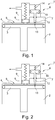
- Fig. 1 and 2 show strictly schematically as a schematic diagram of an embodiment of a compressor unit according to the invention in a portable compressed air source not shown here for the pumping of motor vehicle tires in the case of air loss.
- Fig. 1 represents the normal state.
- Fig. 2 shows the state with activated second dead air volume.
- the compressor unit has a reciprocating compressor 1, which is likewise driven by a sliding crank drive, which is likewise not shown here, with a piston 3 which oscillates in a cylinder 2 and delimits a compression chamber provided with a first dead air volume 4, the cylinder being closed on the output side by a cylinder head 5 with an outlet valve 6 ,
- the reciprocating compressor 1 has a second dead air volume 7, which is connectable via a valve 8 to the compression space.
- the valve 8 is to be opened depending on the pressure in the outlet 9 of the compressor.
- the valve 8 is designed as a spring-loaded spool 10, wherein the piston 11 acts via a guided piston rod 12 to an opening 13 of the compression chamber to the second dead air volume 7 and the opening 13 opens depending on the pressure in the outlet or depending on the pressure in the compression chamber or closes, in the embodiment shown here, depending on the pressure in the outlet 9.
- the piston valve 10 is raised against a correspondingly preselected pressure of the spring 14 after opening of the outlet valve 6.
- the opening 13 between the first dead air volume in the cylinder 2 and at least one further, here the second dead air volume 7 is opened.
- the spool 10 is designed so that the force exerted on the slide force is negligible by the air pressure in the cylinder 2 relative to the force exerted by the air pressure in the outlet 9 force.
- the piston slide 10 and / or the supply line to the slide is designed so that pressure peaks are damped out of the cylinder and cause no opening of the slide.
- the connected Totluftvolumen 7 leads to the pressure limit. With the size of this Totluftvolumens 7 and the pressure of the spring 14 on the slide spool 10, the maximum pressure of the compressor can be preselected.
- the spool 10 closes the opening 13 and the compressor returns to its normal operating state.
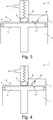
- Fig. 3 represents the normal state.
- Fig. 4 shows the state with activated second dead air volume.
- Fig. 5 shows for clarification the experimentally determined relationship between the size of the second dead air volume and maximum pressure reached an air compressor with 33.0 mm piston diameter and 7.5 mm piston stroke. In the desired final pressure range between 450 kPa and 650 kPa, this relationship is approximately linear.
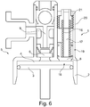
- Fig. 6 shows a compressor unit, in which the further Totluftvolumen variable and depending on the pressure in the compression chamber or in the first Totluftvolumen 4 is continuously variable in its content.
- valve 8 is formed as an end portion of a loaded by a spring 16 piston slide 17 and opens or closes the opening 18 to the adjacent formed in the cylinder head further Totluftvolumen 19.
- the opening or closing and the provision and release of a pressure-dependent increasing or decreasing further Totluftvolumens 19th takes place by the pressure-dependent displacement of the spring-loaded piston slide 17 upwards.
- the trained as a support of the spring spring bushing 21 may be more or less deeply screwed into the internally threaded guide sleeve 20, so that the spring tension and thus the set pressure are adjustable.
Landscapes
- Engineering & Computer Science (AREA)
- Mechanical Engineering (AREA)
- General Engineering & Computer Science (AREA)
- Compressor (AREA)
- Compressors, Vaccum Pumps And Other Relevant Systems (AREA)
Description
- Die Erfindung betrifft eine Kompressoreinheit in einer tragbaren Druckluftquelle, welche einen über ein Schubkurbelgetriebe angetriebenen Hubkolbenverdichter mit einem in einem Zylinder oszillierend bewegten Kolben aufweist, der einen mit einem ersten Totluftvolumen versehenen Kompressionsraum begrenzt, wobei der Zylinder ausgangsseitig durch einen Zylinderkopf mit Auslassventil verschlossen ist
- Solche Kompressoreinheiten werden z. B. mit oder als Teil von Vorrichtungen zum Abdichten und Aufpumpen aufblasbarer Gegenstände, insbesondere zum Abdichten und Aufpumpen von Kraftfahrzeugreifen benötigt (Pannensets).
- Diese tragbaren und leichten Vorrichtungen beinhalten die Kompressoreinheit als Druckgasquelle auf, weisen weiterhin einen Dichtmittelbehälter für ein in den aufblasbaren Gegenstand einfüllbares selbsttätiges Dichtmittel auf, eine Ventil- und Verteilereinheit für Dichtmittel und Druckgas und sind mit einer an die Druckgasquelle anschließbaren Einlassleitung und einer an den aufblasbaren Gegenstand anschließbaren Auslassleitung versehen.
- Bei solchen Vorrichtungen ist der maximale Druck im System entweder durch den maximal erreichbaren Druck des Kompressors festgelegt, wobei der Maximaldruck dann bauartbedingt maßgeblich vom so genannten "Totvolumen" des Zylinders abhängt, oder wird durch ein Druckbegrenzungsventil bestimmt.
- Da mit den genannten Luftkompressoren während der Behebung einer Reifenpanne auch ein Dichtmittel in den Reifen gepresst wird, kann bei der Druckbegrenzung durch ein Überdruckventil in manchen Betriebszuständen durch Öffnen dieses Ventils Dichtmittel unter hohem Druck unerwünscht austreten und/oder in den Zylinder des Kompressors gelangen. Dieser Fall tritt z.B. ein, wenn das Reifenventil während der Befüllung mit Dichtmittel verstopft und sich im Luftkompressor so ein unzulässig hoher Druck aufbaut. Die bisher benutzten Begrenzungsventile öffnen dabei auf der Hochdruckseite und lassen einen Volumenstrom auf der Hochdruckseite aus dem System austreten. Wenn Dichtmittel auch nur in geringen Umfang in den Kompressor und die anschließenden Leitungen gelangt, können durch diesen Rückfluss entweder die Manometerfunktion oder auch das Auslassventil des Kompressors in seiner Funktion beeinträchtigt werden.
- Eine solche Lösung zeigt die die
DE 44 29 097 A1 . Dort ist eine Kompressoreinheit bzw. einen Kolbenverdichter mit einem im Stand der Technik üblichen Auslassventil offenbart, welches gleichzeitig das einzige "Überdruckventil" für den Innenraum des Kompressors ist. Ein solches Auslassventil besteht aus einer federbelasteten Scheibe, welche eine Auslassbohrung des Verdichtungsraums im Zylinder abdeckt und bei entsprechendem Druck im Verdichtungsraum gegen die Feder abhebt. Abgesehen davon, dass ein solches Auslassventil für sehr hohe Öffnungsfrequenzen, d.h. für sehr schnell bewegte Kolbenkompressoren mit kurzem Hub, nur bedingt geeignet ist, ist es hier erforderlich, einen bestimmten Rohrlängenabstand zum Dichtmittelbehälter bzw. zur zugehörigen Verteilereinheit einzuhalten, um einen Rückfluss von Dichtmittel in den Kompressionsraum/Druckraum zu verhindern. Dies erhöht insgesamt die Baugröße von Vorrichtungen zum Abdichten und Aufpumpen aufblasbarer Gegenstände. - Weiter ist eine Kompressoreinheit mit einem Motor und einem über einen Schubkurbeltrieb angetriebenen Hubkolbenverdichter aus den Druckschriften
DE 10 2011 050 714 A1 undDE10 2005 060 320 A1 bekannt. - Wird in die Zuleitung zum geschädigten Reifen zur Verhinderung eines Dichtmittelrückfluss ein zusätzliches Rückschlagventil eingebaut, so verhindert dieses Rückschlagventil nachteiligerweise eine genaue Druckmessung in dem zu reparierenden Reifen.
- Ein Totvolumen ist bei jedem Hubkolbenverdichter vorhanden, da ja der Kolbenboden im oberen Totpunkt einen gewissen und von Null verschiedenen Abstand zur Innenoberfläche des Zylinderkopfes haben muss. Bei einer "Druckbegrenzung" durch ein entsprechend groß ausgelegtes Totluftvolumen, d.h. durch einen großen Abstand zwischen Kolbenboden und Innenoberfläche des Zylinderkopfes besteht die Gefahr eines Dichtmittelaustritts nicht, da kein Luft bzw. Luft/Dichtmittelgemisch in die Umgebung abgelassen wird. Ein entsprechend ausgelegtes Totluftvolumens im Kompressor vermindert jedoch dessen Effizienz und erfordert so einen unnötig großen bzw. teuren Kompressor zum Erreichen einer vorgegebenen Spezifikation.
- Handelsübliche Pannensets zur Reifenabdichtung, die über einen Kleinkompressor verfügen, mit dessen Hilfe Reifen aufgepumpt werden können, nutzen zur Begrenzung des Maximaldruckes in der Regel also entweder das Auslassventil im Kompressionsraum oder aber ein Ventil in den in Strömungsrichtung dem Kompressionsraum nach gelagerten Leitungen, z. B. in der nachfolgenden Verteilereinheit, welches somit zwischen Auslassventil und Reifenventil bzw. zwischen Kompressor und Manometer angeordnet ist.
- Für die Erfindung bestand daher die Aufgabe, eine Kompressoreinheit mit einem Hubkolbenverdichter bereitzustellen, bei der die Begrenzung des Maximaldrucks im Kompressionsraum bei gleichzeitiger Vermeidung von Dichtmittelrückfluß gewährleistet ist, bei der ein plötzlich auf der Hochdruckseite aus dem System austretenden Volumenstrom vermieden wird und bei der bei einfacher Bauweise insgesamt die Gebrauchsdauer und Zuverlässigkeit des Kompressors erhöht wird.
- Gelöst wird diese Aufgabe durch die Merkmale des Hauptanspruchs. Weitere vorteilhafte Ausbildungen sind in den Unteransprüchen offenbart.
- Dabei ist der Kompressionsraum über ein Ventil mit mindestens einem weiteren Totluftvolumen verbindbar. So erfolgt nicht nur eine mechanisch arbeitende Maximaldruckbegrenzung für einen Luftkompressor, bei der zu keinem Zeitpunkt ein Luftstrom in die Umgebung des Kompressors abgeführt wird und die Effizienz des Kompressors innerhalb seines Arbeitsbereiches nicht verringert wird, es wird gleichermaßen auch die Größe des gesamten Totluftvolumens, d.h. der Inhalt des ersten und weiteren Totluftvolumens in Abhängigkeit von verschiedenen Betriebszuständen der Kompressoreinheit gesteuert bzw. eingestellt. Es ist damit möglich, das erste Totvolumen des Zylinders zu verringern und dadurch auch den Wirkungsgrad des Kompressors deutlich zu erhöhen und trotzdem ein für die gestellten Anforderungen/Aufgaben ausreichendes weiteres Totluftvolumen zur Verfügung zu haben, welches bei zu hohen Drücken zugeschaltet wird.
- Eine vorteilhafte Weiterbildung besteht darin, dass das zweite Totluftvolumen mit dem Kompressionsraum über das Ventil abhängig vom Druck in der Auslassleitung des Kompressors oder abhängig vom Druck im Kompressionsraum verbindbar ist, vorzugsweise reversibel über das Ventil verbindbar ist, wobei das Ventil vorzugsweise federbelastet ist. Damit wird die Druckstufe, an der das Ventil anspricht und bei der das Ventil öffnet, sehr gut einstellbar und die Auslegung wird vereinfacht.
- Eine weitere vorteilhafte Ausbildung besteht darin, dass das weitere Totluftvolumen variabel ist und sich abhängig vom Druck in der Auslassleitung des Kompressors oder abhängig vom Druck im Kompressionsraum kontinuierlich in seinem Inhalt verändern lässt. Eine solche druckabhängig variable Veränderung des aus dem Inhalt des ersten und weiteren Totluftvolmen bestehenden Gesamtinhalt des zur Verfügung stehenden Totluftvolumens erlaubt eine tatsächlich an den Betriebszustand des Kompressors gekoppelte Steuerung bzw. eine durch die Rückkopplung auch im Sinne einer Regelung arbeitende variable Einstellung des Totluftvolumens über den gesamten Arbeitsbereich.
- Vorteilhafte konstruktive Ausbildungen einer solchen druckabhängig variable Veränderung des Totluftvolumens können dadurch erfolgen, das entweder das weitere Totluftvolumen gegen druckabhängig belastbare Federn oder durch ein auf Druckänderungen reagierendes elektromechanisches Stellglied kontinuierlich veränderbar ist.
- Eine weitere vorteilhafte Ausbildung besteht darin, dass das Ventil eine Drosseleinrichtung zur Dämpfung von Druckspitzen aus dem Zylinder bzw. Kompressionsraum beinhaltet. Damit werden Stöße und Schwingungen der Luftsäule vermieden, die die Funktion der Zuschaltung des zweiten Totluftvolumens stören könnten.
- Eine weitere vorteilhafte Ausbildung besteht darin, dass das Totluftvolumen mit dem Kompressionsraum irreversibel über das Ventil verbindbar ist, beispielsweise über ein bei einem Nenndruck öffnenden Berstventil. Dadurch wird die Konstruktion sehr einfach, allerdings nimmt man dabei in Kauf, dass in dem Moment, in dem der Druck in der Auslassleitung des Kompressors zu einem bestimmten Zeitpunkt wieder unter den zulässigen Wert sinkt, der Kompressor mit verringerter Effizienz weiter arbeitet, da das zweite Totluftvolumen nicht wieder abgetrennt wird.
- Eine weitere vorteilhafte Ausbildung besteht darin, dass das Ventil ein manuell wieder verschließbares Ventil ist, vorzugsweise ein Ventil mit einem von außen sichtbaren Indikator für die Offen-Stellung. Auch hier ist die Konstruktion sehr vereinfacht, wobei aber trotzdem eine Rückstellung manuell möglich ist und der Kompressor mit der ursprünglichen Effizient weiter betrieben werden kann.
- Besonders geeignet ist solch eine Kompressoreinheit zur Anwendung mit einer Vorrichtung zum Abdichten und Aufpumpen aufblasbarer Gegenstände, insbesondere zum Abdichten und Aufpumpen von Kraftfahrzeugreifen.
- Anhand eines Ausführungsbeispiels soll die Erfindung näher erläutert werden. Es zeigen
- Fig. 1
- eine erfindungsgemäße Kompressoreinheit, bei der das zweite Totluftvolumen mit dem Kompressionsraum reversibel verbindbar ist, im Normalzustand.
- Fig. 2
- eine erfindungsgemäße Kompressoreinheit gemäß
Fig. 1 im Zustand mit zugeschaltetem zweitem Totluftvolumen - Fig. 3
- ein weiteres Ausführungseispiel einer erfindungsgemäßen Kompressoreinheit, bei der das zweite Totluftvolumen mit dem Kompressionsraum irreversibel verbindbar ist, im Normalzustand.
- Fig. 4
- eine erfindungsgemäße Kompressoreinheit gemäß
Fig. 3 im Zustand mit zugeschaltetem zweitem Totluftvolumen. - Fig. 5
- den experimentell bestimmten Zusammenhang zwischen Größe des zweiten Totluftvolumens sowie erreichtem Maximaldruck eines Luftkompressors in einem Diagramm
- Fig. 6
- eine erfindungsgemäße Kompressoreinheit, bei der das Totluftvolumen variabel und abhängig vom Druck im Kompressionsraum veränderbar ist.
-
Fig. 1 und 2 zeigen streng schematisch als Prinzipskizze ein Ausführungsbeispiel einer erfindungsgemäßen Kompressoreinheit in einer hier nicht näher dargestellten tragbaren Druckluftquelle für das Aufpumpen von Kraftfahrzeugreifen im Fall des Luftverlustes.Fig. 1 stellt den Normalzustand dar.Fig. 2 zeigt den Zustand mit zugeschaltetem zweitem Totluftvolumen. - Die Kompressoreinheit weist einen über ein hier ebenfalls nicht dargestelltes Schubkurbelgetriebe angetriebenen Hubkolbenverdichter 1 mit einem in einem Zylinder 2 oszillierend bewegten Kolben 3 auf, der einen mit einem ersten Totluftvolumen 4 versehenen Kompressionsraum begrenzt, wobei der Zylinder ausgangsseitig durch einen Zylinderkopf 5 mit Auslassventil 6 verschlossen ist.
- Der Hubkolbenverdichter 1 weist ein zweites Totluftvolumen 7 auf, welches über ein Ventil 8 mit dem Kompressionsraum verbindbar ist. Das Ventil 8 ist abhängig vom Druck in der Auslassleitung 9 des Kompressors zu öffnen.
- Das Ventil 8 ist dabei als federbelasteter Kolbenschieber 10 ausgebildet ist, wobei der Kolben 11 über eine geführte Kolbenstange 12 auf eine Öffnung 13 des Kompressionsraumes zum zweiten Totluftvolumen 7 wirkt und die Öffnung 13 abhängig vom Druck in der Auslassleitung oder abhängig vom Druck im Kompressionsraum öffnet oder schließt, in der hier gezeigten Ausbildung abhängig vom Druck in der Auslassleitung 9.
- Im Normalbetrieb existiert nahezu kein erstes Totluftvolumen zwischen Kolben 3 und Zylinderdeckel bzw. Zylinderkopf 5. Durch eine periodische Kolbenbewegung wird nach dem bekannten Prinzip ein Luftstrom über das Auslassventil 6 durch die Auslassleitung 9 befördert. In diesem Betriebszustand wird die Effizienz des Kompressors nicht beeinträchtigt.
- Steigt nun der Druck in der Auslassleitung 9 bzw. im ersten Totluftvolumen 4 im Kompressionsraum über einen zulässigen Wert an, so wird nach Öffnung des Auslassventils 6 der Kolbenschieber 10 gegen einen entsprechend vorgewählten Druck der Feder 14 angehoben. Durch das Anheben des Kolbenschiebers 10 wird die Öffnung 13 zwischen dem ersten Totluftvolumen im Zylinder 2 und mindestens einem weiteren, hier dem zweiten Totluftvolumen 7 geöffnet.
- Hierbei ist der Kolbenschieber 10 so ausgelegt, dass die auf den Schieber ausgeübte Kraft durch den Luftdruck im Zylinder 2 gegenüber der durch den Luftdruck in der Auslassleitung 9 ausgeübten Kraft zu vernachlässigen ist.
- Weiterhin ist der Kolbenschieber 10 und/oder die Zuleitung zu dem Schieber so ausgelegt, dass Druckspitzen aus dem Zylinder abgedämpft werden und keine Öffnung des Schiebers hervorrufen. Das zugeschaltete Totluftvolumen 7 führt zur Druckbegrenzung. Mit der Größe dieses Totluftvolumens 7 sowie dem Druck der Feder 14 auf den Schieber Kolbenschieber 10 kann der Maximaldruck des Kompressors vorgewählt werden.
- Sinkt der Druck im Luftauslass zu einem bestimmten Zeitpunkt wieder unter den zulässigen Wert, so schließt der Kolbenschieber 10 die Öffnung 13 und der Kompressor kehrt wieder in seinen normalen Betriebszustand zurück.
-
Fig. 3 und 4 zeigen entsprechend ein Ausführungsbeispiel einer erfindungsgemäßen Kompressoreinheit in einer hier nicht näher dargestellten tragbaren Druckluftquelle für das Aufpumpen von Kraftfahrzeugreifen im Fall des Luftverlustes, bei der das Ventil ein irreversibel bei einem Nenndruck öffnendes Berstventil 15 ist. -
Fig. 3 stellt den Normalzustand dar.Fig. 4 zeigt den Zustand mit zugeschaltetem zweitem Totluftvolumen. - Wie schon beim vorher beschriebenen Ausführungsbeispiel der
Fig. 1 und 2 existiert im Normalbetrieb nahezu kein erstes Totluftvolumen zwischen Kolben 3 und Zylinderdeckel bzw. Zylinderkopf 5, d.h. der Kompressor arbeitet ohne Effizienzeinschränkung. - Steigt nun der Druck in der Auslassleitung 9 bzw. im ersten Totluftvolumen 4 im Kompressionsraum über einen zulässigen Wert an, so wird der Verschluss bzw. das Berstventil 15 gegen einen entsprechend vorgewählte Haltekraft aufgebrochen. Hierdurch wird die Öffnung 13 zwischen dem Kompressionsraum und dem zweiten Totluftvolumen 7 geöffnet. Mit der Größe dieses Totluftvolumens 7 ist danach der Maximaldruck des Kompressors vorbestimmt.
- Sinkt der Druck in der Auslassleitung 9 bzw. im ersten Totluftvolumen 4 im Kompressionsraum zu einem bestimmten Zeitpunkt wieder unter den zulässigen Wert, arbeitet der Kompressor mit verringerter Effizienz weiter, da das zweite Totluftvolumen 7 nicht wieder abgeschlossen wird.
-
Fig. 5 zeigt zur Verdeutlichung den experimentell bestimmten Zusammenhang zwischen Größe des zweiten Totluftvolumens sowie erreichtem Maximaldruck eines Luftkompressors mit 33,0 mm Kolbendurchmesser und 7,5 mm Kolbenhub. Im erwünschten Enddruckbereich zwischen 450 kPa und 650 kPa ist dieser Zusammenhang annähernd linear. -
Fig. 6 zeigt eine Kompressoreinheit, bei der das weitere Totluftvolumen variabel und abhängig vom Druck im Kompressionsraum bzw. im ersten Totluftvolumen 4 kontinuierlich in seinem Inhalt veränderbar ist. - Hierzu ist das Ventil 8 als Endteil eines durch eine Feder 16 belasteten Kolbenschiebers 17 ausgebildet und öffnet oder schließt die Öffnung 18 zum angrenzenden im Zylinderkopf ausgebildeten weiteren Totluftvolumen 19. Das Öffnen oder Schließen und die Bereitstellung und Freigabe eines druckabhängig sich vergrößernden oder verkleinernden weiteren Totluftvolumens 19 erfolgt durch das druckabhängige Verschieben des federbelasteten Kolbenschiebers 17 nach oben.
- Die als Abstützung der Feder ausgebildete Federbuchse 21 kann mehr oder weniger tief in die mit Innengewinde versehene Führungshülse 20 eingeschraubt sein, so dass die Federspannung und damit der Ansprechdruck einstellbar sind.
-
- 1 Hubkolbenverdichter
- 2 Zylinder
- 3 Kolben
- 4 Erstes Totluftvolumen
- 5 Zylinderkopf
- 6 Auslassventil
- 7 Zweites Totluftvolumen
- 8 Ventil
- 9 Auslassleitung
- 10 Kolbenschieber
- 11 Kolben
- 12 Kolbenstange
- 13 Öffnung
- 14 Feder
- 15 Berstventil
- 16 Feder
- 17 Kolbenschieber
- 18 Öffnung
- 19 Variables Totluftvolumen
- 20 Führungshülse
- 21 Federbuchse
Claims (14)
- Kompressoreinheit in einer tragbaren Druckluftquelle, welche einen über ein Schubkurbelgetriebe angetriebenen Hubkolbenverdichter (1) mit einem in einem Zylinder (2) oszillierend bewegten Kolben (3) aufweist, der einen mit einem ersten Totluftvolumen (4) versehenen Kompressionsraum begrenzt, wobei der Zylinder (2) ausgangsseitig durch einen Zylinderkopf (5) mit Auslassventil (6) verschlossen ist, dadurch gekennzeichnet, dass der Kompressionsraum über mindestens ein Ventil (8) mit mindestens einem weiteren Totluftvolumen (7) verbindbar ist.
- Kompressoreinheit nach Anspruch 1, bei der das weitere Totluftvolumen (7) mit dem Kompressionsraum über das Ventil (8) abhängig vom Druck in der Auslassleitung (9) des Kompressors oder abhängig vom Druck im Kompressionsraum verbindbar ist.
- Kompressoreinheit nach Anspruch 1 oder 2, bei der das weitere Totluftvolumen (19) variabel und abhängig vom Druck in der Auslassleitung (9) des Kompressors oder abhängig vom Druck im Kompressionsraum kontinuierlich in seinem Inhalt veränderbar ist.
- Kompressoreinheit nach einem der Ansprüche 1 bis 3, bei der das weitere variable Totluftvolumen (19) durch ein elektromechanisches Stellglied kontinuierlich veränderbar ist.
- Kompressoreinheit nach einem der Ansprüche 1 bis 4, bei der das Ventil (8) eine Drosseleinrichtung zur Dämpfung von Druckspitzen aus dem Zylinder (2) bzw. aus dem Kompressionsraum beinhaltet.
- Kompressoreinheit nach einem der Ansprüche 1 bis 5, bei der das weitere Totluftvolumen mit dem Kompressionsraum reversibel über das Ventil (8) verbindbar ist, wobei das Ventil vorzugsweise federbelastet ist.
- Kompressoreinheit nach einem der Ansprüche 1 bis 6, bei der das Ventil (8) als federbelasteter Kolbenschieber (10) ausgebildet ist, wobei dessen Kolben (11) über eine geführte Kolbenstange (12) auf eine Öffnung (13) des Kompressionsraumes zum weiteren Totluftvolumen (7) wirkt und die Öffnung (13) abhängig vom Druck in der Auslassleitung (9) oder abhängig vom Druck im Kompressionsraum öffnet oder schließt.
- Kompressoreinheit nach einem der Ansprüche 1 bis 6, bei der das Ventil (8) als Endteil eines durch eine Feder (16) belasteten Kolbenschiebers (17) ausgebildet ist, und auf eine Öffnung (18) des Kompressionsraumes zum weiteren variablen Totluftvolumen (19) wirkt, die Öffnung (13) abhängig vom Druck in der Auslassleitung (9) oder abhängig vom Druck im Kompressionsraum (4) öffnet oder schließt und bei der die Bereitstellung des variablen und druckabhängig sich vergrößernden oder verkleinernden weiteren Totluftvolumens (19) durch das druckabhängige Verschieben des federbelasteten Kolbenschiebers (17) innerhalb einer Führungshülse (20) erfolgt.
- Kompressoreinheit nach Anspruch 8, bei der die die Führungshülse (20) ein Innengewinde aufweist und die Belastung des Kolbenschiebers (17) durch die Feder (16) über eine Federbuchse (21) einstellbar ist, die mehr oder weniger tief in die Führungshülse (20) einschraubbar ist
- Kompressoreinheit nach einem der Ansprüche 1 bis 5, bei der das weitere Totluftvolumen (7, 19) mit dem Kompressionsraum irreversibel über das Ventil verbindbar ist.
- Kompressoreinheit nach Anspruch 10, bei der das Ventil ein manuell wieder verschließbares Ventil ist, vorzugsweise ein Ventil mit einem von außen sichtbaren Indikator für die Offen-Stellung.
- Kompressoreinheit nach Anspruch 10, bei der das Ventil ein irreversibel bei einem Nenndruck öffnendes Ventil ist, vorzugsweise ein Berstventil (15) ist.
- Verwendung einer Kompressoreinheit nach einem der Ansprüche 1 bis 12 zum Abdichten und Aufpumpen von Kraftfahrzeugreifen.
- Pannenset zur Reparatur von Kraftfahrzeugreifen mit einer Kompressoreinheit nach einem der Ansprüche 1 bis 12.
Priority Applications (1)
| Application Number | Priority Date | Filing Date | Title |
|---|---|---|---|
| PL14717144T PL3025059T3 (pl) | 2013-07-23 | 2014-04-14 | Sprężarka z ograniczeniem ciśnienia |
Applications Claiming Priority (2)
| Application Number | Priority Date | Filing Date | Title |
|---|---|---|---|
| DE201310107850 DE102013107850A1 (de) | 2013-07-23 | 2013-07-23 | Kompressor mit Druckbegrenzung |
| PCT/EP2014/057465 WO2015010799A1 (de) | 2013-07-23 | 2014-04-14 | Kompressor mit druckbegrenzung |
Publications (2)
| Publication Number | Publication Date |
|---|---|
| EP3025059A1 EP3025059A1 (de) | 2016-06-01 |
| EP3025059B1 true EP3025059B1 (de) | 2019-06-12 |
Family
ID=50483378
Family Applications (1)
| Application Number | Title | Priority Date | Filing Date |
|---|---|---|---|
| EP14717144.1A Active EP3025059B1 (de) | 2013-07-23 | 2014-04-14 | Kompressor mit druckbegrenzung |
Country Status (6)
| Country | Link |
|---|---|
| EP (1) | EP3025059B1 (de) |
| JP (1) | JP6254696B2 (de) |
| CN (1) | CN105392988B (de) |
| DE (1) | DE102013107850A1 (de) |
| PL (1) | PL3025059T3 (de) |
| WO (1) | WO2015010799A1 (de) |
Families Citing this family (3)
| Publication number | Priority date | Publication date | Assignee | Title |
|---|---|---|---|---|
| DE102014205067A1 (de) | 2014-03-19 | 2015-09-24 | Continental Reifen Deutschland Gmbh | Vorrichtung zum Abdichten und Aufpumpen aufblasbarer Gegenstände |
| DE102017212040A1 (de) * | 2017-07-13 | 2019-01-17 | Continental Reifen Deutschland Gmbh | Verfahren zur gewichtsabhängigen Regelung des Innendrucks eines durch eine Gewichts- oder Traglast belasteten Tragkörpers |
| DE102019217779A1 (de) | 2019-04-26 | 2020-10-29 | Continental Reifen Deutschland Gmbh | Tragbares/transportables System zum Abdichten und Aufpumpen von Fahrzeugluftreifen mit gradliniger Druckluftströmung |
Family Cites Families (12)
| Publication number | Priority date | Publication date | Assignee | Title |
|---|---|---|---|---|
| US3972652A (en) * | 1975-05-14 | 1976-08-03 | Dresser Industries, Inc. | Variable volume clearance chamber for compressors |
| JPH02173369A (ja) * | 1988-12-27 | 1990-07-04 | Mitsubishi Heavy Ind Ltd | ガス圧縮機の容量制御装置 |
| DE4429097A1 (de) | 1994-08-17 | 1996-02-22 | Thurner Bayer Druckguss | Kolbenverdichter für gasförmige Medien |
| US6945062B2 (en) * | 2003-12-04 | 2005-09-20 | Carrier Corporation | Heat pump water heating system including a compressor having a variable clearance volume |
| JP4420740B2 (ja) * | 2004-05-27 | 2010-02-24 | 株式会社ブリヂストン | ポンプアップ装置 |
| DE102005060320A1 (de) * | 2005-12-16 | 2007-06-21 | Continental Aktiengesellschaft | Kompressoreinheit |
| DE102007051940A1 (de) * | 2007-10-29 | 2009-04-30 | Knorr-Bremse Systeme für Nutzfahrzeuge GmbH | Aufgeladener Kompressor und Verfahren zur Steuerung eines aufgeladenen Kompressors |
| JP5047234B2 (ja) * | 2009-07-13 | 2012-10-10 | 株式会社日本製鋼所 | 往復動圧縮機 |
| CN201953605U (zh) * | 2010-12-17 | 2011-08-31 | 靳北彪 | 放出式高效气体压缩机 |
| DE102011050714A1 (de) * | 2011-05-30 | 2012-12-06 | Continental Reifen Deutschland Gmbh | Kompressoreinheit |
| DE102011050806A1 (de) * | 2011-06-01 | 2012-12-06 | Continental Reifen Deutschland Gmbh | Kompressor mit Druckbegrenzung |
| CN202914274U (zh) * | 2012-11-16 | 2013-05-01 | 沈阳远大压缩机股份有限公司 | 压缩机气缸余隙调节装置 |
-
2013
- 2013-07-23 DE DE201310107850 patent/DE102013107850A1/de not_active Withdrawn
-
2014
- 2014-04-14 PL PL14717144T patent/PL3025059T3/pl unknown
- 2014-04-14 EP EP14717144.1A patent/EP3025059B1/de active Active
- 2014-04-14 WO PCT/EP2014/057465 patent/WO2015010799A1/de not_active Ceased
- 2014-04-14 JP JP2016526473A patent/JP6254696B2/ja active Active
- 2014-04-14 CN CN201480041210.3A patent/CN105392988B/zh active Active
Non-Patent Citations (1)
| Title |
|---|
| None * |
Also Published As
| Publication number | Publication date |
|---|---|
| JP2016525180A (ja) | 2016-08-22 |
| JP6254696B2 (ja) | 2017-12-27 |
| CN105392988B (zh) | 2018-06-08 |
| WO2015010799A1 (de) | 2015-01-29 |
| EP3025059A1 (de) | 2016-06-01 |
| PL3025059T3 (pl) | 2019-12-31 |
| CN105392988A (zh) | 2016-03-09 |
| DE102013107850A1 (de) | 2015-01-29 |
Similar Documents
| Publication | Publication Date | Title |
|---|---|---|
| DE2840445C2 (de) | Hydraulische Vorrichtung zum Betätigen eines Gaswechselventils für Brennkraftmaschinen | |
| AT402542B (de) | Ansaugregelventil | |
| DE10306006A1 (de) | Hydraulikmodul | |
| EP3119595B1 (de) | Vorrichtung zum abdichten und aufpumpen aufblasbarer gegenstände | |
| EP4242779A2 (de) | Ventilanordnung | |
| CH660580A5 (de) | Falzmesserzylinder. | |
| DE1403954C3 (de) | Kompressor zum Fördern von Gas | |
| WO2015010799A1 (de) | Kompressor mit druckbegrenzung | |
| WO1995022694A1 (de) | Vorrichtung zur summenleistungsregelung von wenigstens zwei hydrostatischen verstellpumpen | |
| EP1998045A1 (de) | Verdrängermaschine mit Koaxialventilanordnung | |
| DE102013210556B4 (de) | Vorrichtung zur Höhenverstellung eines Fahrzeugaufbaus | |
| DE102009052076A1 (de) | Ventilanordnung | |
| EP2715136B1 (de) | Kompressoreinheit | |
| WO2012163619A1 (de) | Kompressor mit druckbegrenzung | |
| DE1200148B (de) | Luftkompressor fuer Fahrzeuge od. dgl., insbesondere fuer Druckluftbremsanlagen | |
| EP3055569B1 (de) | Pannenset mit kompressor mit druckbegrenzung | |
| EP0866394B1 (de) | Governor für Druckluftbeschaffungsanlagen von Fahrzeugen | |
| WO2015124155A1 (de) | Spanner für einen zugmitteltrieb mit überdrucksystem im überkopfbau | |
| DE3521818A1 (de) | Dreifachteleskopstempel | |
| WO2007068531A1 (de) | Kompressoreinheit | |
| EP3770444B1 (de) | Anordnung mit einem pneumatischen oder hydraulischen kolbenstangenzylinder | |
| DE102016103958A1 (de) | Pilotgesteuertes Sicherheitsventil | |
| DE463765C (de) | Luftpumpe | |
| DE102019205591A1 (de) | Verfahren zum Betreiben einer Kraftstofffördereinrichtung für kryogene Kraftstoffe | |
| DE1428010C3 (de) | Vorrichtung zur Regelung eines von einer Brennkraftmaschine angetrie benen Verdichters |
Legal Events
| Date | Code | Title | Description |
|---|---|---|---|
| PUAI | Public reference made under article 153(3) epc to a published international application that has entered the european phase |
Free format text: ORIGINAL CODE: 0009012 |
|
| 17P | Request for examination filed |
Effective date: 20160223 |
|
| AK | Designated contracting states |
Kind code of ref document: A1 Designated state(s): AL AT BE BG CH CY CZ DE DK EE ES FI FR GB GR HR HU IE IS IT LI LT LU LV MC MK MT NL NO PL PT RO RS SE SI SK SM TR |
|
| AX | Request for extension of the european patent |
Extension state: BA ME |
|
| DAX | Request for extension of the european patent (deleted) | ||
| GRAP | Despatch of communication of intention to grant a patent |
Free format text: ORIGINAL CODE: EPIDOSNIGR1 |
|
| STAA | Information on the status of an ep patent application or granted ep patent |
Free format text: STATUS: GRANT OF PATENT IS INTENDED |
|
| INTG | Intention to grant announced |
Effective date: 20190104 |
|
| GRAS | Grant fee paid |
Free format text: ORIGINAL CODE: EPIDOSNIGR3 |
|
| GRAA | (expected) grant |
Free format text: ORIGINAL CODE: 0009210 |
|
| STAA | Information on the status of an ep patent application or granted ep patent |
Free format text: STATUS: THE PATENT HAS BEEN GRANTED |
|
| AK | Designated contracting states |
Kind code of ref document: B1 Designated state(s): AL AT BE BG CH CY CZ DE DK EE ES FI FR GB GR HR HU IE IS IT LI LT LU LV MC MK MT NL NO PL PT RO RS SE SI SK SM TR |
|
| REG | Reference to a national code |
Ref country code: GB Ref legal event code: FG4D Free format text: NOT ENGLISH |
|
| REG | Reference to a national code |
Ref country code: CH Ref legal event code: EP |
|
| REG | Reference to a national code |
Ref country code: AT Ref legal event code: REF Ref document number: 1142894 Country of ref document: AT Kind code of ref document: T Effective date: 20190615 |
|
| REG | Reference to a national code |
Ref country code: DE Ref legal event code: R096 Ref document number: 502014011926 Country of ref document: DE |
|
| REG | Reference to a national code |
Ref country code: IE Ref legal event code: FG4D Free format text: LANGUAGE OF EP DOCUMENT: GERMAN |
|
| REG | Reference to a national code |
Ref country code: NL Ref legal event code: MP Effective date: 20190612 |
|
| REG | Reference to a national code |
Ref country code: LT Ref legal event code: MG4D |
|
| PG25 | Lapsed in a contracting state [announced via postgrant information from national office to epo] |
Ref country code: HR Free format text: LAPSE BECAUSE OF FAILURE TO SUBMIT A TRANSLATION OF THE DESCRIPTION OR TO PAY THE FEE WITHIN THE PRESCRIBED TIME-LIMIT Effective date: 20190612 Ref country code: LT Free format text: LAPSE BECAUSE OF FAILURE TO SUBMIT A TRANSLATION OF THE DESCRIPTION OR TO PAY THE FEE WITHIN THE PRESCRIBED TIME-LIMIT Effective date: 20190612 Ref country code: FI Free format text: LAPSE BECAUSE OF FAILURE TO SUBMIT A TRANSLATION OF THE DESCRIPTION OR TO PAY THE FEE WITHIN THE PRESCRIBED TIME-LIMIT Effective date: 20190612 Ref country code: NO Free format text: LAPSE BECAUSE OF FAILURE TO SUBMIT A TRANSLATION OF THE DESCRIPTION OR TO PAY THE FEE WITHIN THE PRESCRIBED TIME-LIMIT Effective date: 20190912 Ref country code: AL Free format text: LAPSE BECAUSE OF FAILURE TO SUBMIT A TRANSLATION OF THE DESCRIPTION OR TO PAY THE FEE WITHIN THE PRESCRIBED TIME-LIMIT Effective date: 20190612 Ref country code: SE Free format text: LAPSE BECAUSE OF FAILURE TO SUBMIT A TRANSLATION OF THE DESCRIPTION OR TO PAY THE FEE WITHIN THE PRESCRIBED TIME-LIMIT Effective date: 20190612 |
|
| PG25 | Lapsed in a contracting state [announced via postgrant information from national office to epo] |
Ref country code: BG Free format text: LAPSE BECAUSE OF FAILURE TO SUBMIT A TRANSLATION OF THE DESCRIPTION OR TO PAY THE FEE WITHIN THE PRESCRIBED TIME-LIMIT Effective date: 20190912 Ref country code: GR Free format text: LAPSE BECAUSE OF FAILURE TO SUBMIT A TRANSLATION OF THE DESCRIPTION OR TO PAY THE FEE WITHIN THE PRESCRIBED TIME-LIMIT Effective date: 20190913 Ref country code: RS Free format text: LAPSE BECAUSE OF FAILURE TO SUBMIT A TRANSLATION OF THE DESCRIPTION OR TO PAY THE FEE WITHIN THE PRESCRIBED TIME-LIMIT Effective date: 20190612 Ref country code: LV Free format text: LAPSE BECAUSE OF FAILURE TO SUBMIT A TRANSLATION OF THE DESCRIPTION OR TO PAY THE FEE WITHIN THE PRESCRIBED TIME-LIMIT Effective date: 20190612 |
|
| PG25 | Lapsed in a contracting state [announced via postgrant information from national office to epo] |
Ref country code: EE Free format text: LAPSE BECAUSE OF FAILURE TO SUBMIT A TRANSLATION OF THE DESCRIPTION OR TO PAY THE FEE WITHIN THE PRESCRIBED TIME-LIMIT Effective date: 20190612 Ref country code: SK Free format text: LAPSE BECAUSE OF FAILURE TO SUBMIT A TRANSLATION OF THE DESCRIPTION OR TO PAY THE FEE WITHIN THE PRESCRIBED TIME-LIMIT Effective date: 20190612 Ref country code: PT Free format text: LAPSE BECAUSE OF FAILURE TO SUBMIT A TRANSLATION OF THE DESCRIPTION OR TO PAY THE FEE WITHIN THE PRESCRIBED TIME-LIMIT Effective date: 20191014 Ref country code: RO Free format text: LAPSE BECAUSE OF FAILURE TO SUBMIT A TRANSLATION OF THE DESCRIPTION OR TO PAY THE FEE WITHIN THE PRESCRIBED TIME-LIMIT Effective date: 20190612 Ref country code: CZ Free format text: LAPSE BECAUSE OF FAILURE TO SUBMIT A TRANSLATION OF THE DESCRIPTION OR TO PAY THE FEE WITHIN THE PRESCRIBED TIME-LIMIT Effective date: 20190612 Ref country code: NL Free format text: LAPSE BECAUSE OF FAILURE TO SUBMIT A TRANSLATION OF THE DESCRIPTION OR TO PAY THE FEE WITHIN THE PRESCRIBED TIME-LIMIT Effective date: 20190612 |
|
| PG25 | Lapsed in a contracting state [announced via postgrant information from national office to epo] |
Ref country code: IS Free format text: LAPSE BECAUSE OF FAILURE TO SUBMIT A TRANSLATION OF THE DESCRIPTION OR TO PAY THE FEE WITHIN THE PRESCRIBED TIME-LIMIT Effective date: 20191012 Ref country code: SM Free format text: LAPSE BECAUSE OF FAILURE TO SUBMIT A TRANSLATION OF THE DESCRIPTION OR TO PAY THE FEE WITHIN THE PRESCRIBED TIME-LIMIT Effective date: 20190612 Ref country code: ES Free format text: LAPSE BECAUSE OF FAILURE TO SUBMIT A TRANSLATION OF THE DESCRIPTION OR TO PAY THE FEE WITHIN THE PRESCRIBED TIME-LIMIT Effective date: 20190612 Ref country code: IT Free format text: LAPSE BECAUSE OF FAILURE TO SUBMIT A TRANSLATION OF THE DESCRIPTION OR TO PAY THE FEE WITHIN THE PRESCRIBED TIME-LIMIT Effective date: 20190612 |
|
| REG | Reference to a national code |
Ref country code: DE Ref legal event code: R097 Ref document number: 502014011926 Country of ref document: DE |
|
| PG25 | Lapsed in a contracting state [announced via postgrant information from national office to epo] |
Ref country code: TR Free format text: LAPSE BECAUSE OF FAILURE TO SUBMIT A TRANSLATION OF THE DESCRIPTION OR TO PAY THE FEE WITHIN THE PRESCRIBED TIME-LIMIT Effective date: 20190612 |
|
| PLBE | No opposition filed within time limit |
Free format text: ORIGINAL CODE: 0009261 |
|
| STAA | Information on the status of an ep patent application or granted ep patent |
Free format text: STATUS: NO OPPOSITION FILED WITHIN TIME LIMIT |
|
| PG25 | Lapsed in a contracting state [announced via postgrant information from national office to epo] |
Ref country code: DK Free format text: LAPSE BECAUSE OF FAILURE TO SUBMIT A TRANSLATION OF THE DESCRIPTION OR TO PAY THE FEE WITHIN THE PRESCRIBED TIME-LIMIT Effective date: 20190612 |
|
| 26N | No opposition filed |
Effective date: 20200313 |
|
| PG25 | Lapsed in a contracting state [announced via postgrant information from national office to epo] |
Ref country code: IS Free format text: LAPSE BECAUSE OF FAILURE TO SUBMIT A TRANSLATION OF THE DESCRIPTION OR TO PAY THE FEE WITHIN THE PRESCRIBED TIME-LIMIT Effective date: 20200224 Ref country code: SI Free format text: LAPSE BECAUSE OF FAILURE TO SUBMIT A TRANSLATION OF THE DESCRIPTION OR TO PAY THE FEE WITHIN THE PRESCRIBED TIME-LIMIT Effective date: 20190612 |
|
| PG2D | Information on lapse in contracting state deleted |
Ref country code: IS |
|
| PG25 | Lapsed in a contracting state [announced via postgrant information from national office to epo] |
Ref country code: MC Free format text: LAPSE BECAUSE OF FAILURE TO SUBMIT A TRANSLATION OF THE DESCRIPTION OR TO PAY THE FEE WITHIN THE PRESCRIBED TIME-LIMIT Effective date: 20190612 |
|
| REG | Reference to a national code |
Ref country code: CH Ref legal event code: PL |
|
| PG25 | Lapsed in a contracting state [announced via postgrant information from national office to epo] |
Ref country code: LU Free format text: LAPSE BECAUSE OF NON-PAYMENT OF DUE FEES Effective date: 20200414 Ref country code: CH Free format text: LAPSE BECAUSE OF NON-PAYMENT OF DUE FEES Effective date: 20200430 Ref country code: LI Free format text: LAPSE BECAUSE OF NON-PAYMENT OF DUE FEES Effective date: 20200430 |
|
| REG | Reference to a national code |
Ref country code: BE Ref legal event code: MM Effective date: 20200430 |
|
| PG25 | Lapsed in a contracting state [announced via postgrant information from national office to epo] |
Ref country code: BE Free format text: LAPSE BECAUSE OF NON-PAYMENT OF DUE FEES Effective date: 20200430 |
|
| PG25 | Lapsed in a contracting state [announced via postgrant information from national office to epo] |
Ref country code: IE Free format text: LAPSE BECAUSE OF NON-PAYMENT OF DUE FEES Effective date: 20200414 |
|
| REG | Reference to a national code |
Ref country code: AT Ref legal event code: MM01 Ref document number: 1142894 Country of ref document: AT Kind code of ref document: T Effective date: 20200414 |
|
| PG25 | Lapsed in a contracting state [announced via postgrant information from national office to epo] |
Ref country code: AT Free format text: LAPSE BECAUSE OF NON-PAYMENT OF DUE FEES Effective date: 20200414 |
|
| PG25 | Lapsed in a contracting state [announced via postgrant information from national office to epo] |
Ref country code: MT Free format text: LAPSE BECAUSE OF FAILURE TO SUBMIT A TRANSLATION OF THE DESCRIPTION OR TO PAY THE FEE WITHIN THE PRESCRIBED TIME-LIMIT Effective date: 20190612 Ref country code: CY Free format text: LAPSE BECAUSE OF FAILURE TO SUBMIT A TRANSLATION OF THE DESCRIPTION OR TO PAY THE FEE WITHIN THE PRESCRIBED TIME-LIMIT Effective date: 20190612 |
|
| PG25 | Lapsed in a contracting state [announced via postgrant information from national office to epo] |
Ref country code: MK Free format text: LAPSE BECAUSE OF FAILURE TO SUBMIT A TRANSLATION OF THE DESCRIPTION OR TO PAY THE FEE WITHIN THE PRESCRIBED TIME-LIMIT Effective date: 20190612 |
|
| REG | Reference to a national code |
Ref country code: DE Ref legal event code: R081 Ref document number: 502014011926 Country of ref document: DE Owner name: CONTINENTAL REIFEN DEUTSCHLAND GMBH, DE Free format text: FORMER OWNER: CONTINENTAL REIFEN DEUTSCHLAND GMBH, 30165 HANNOVER, DE |
|
| PGFP | Annual fee paid to national office [announced via postgrant information from national office to epo] |
Ref country code: FR Payment date: 20240425 Year of fee payment: 11 |
|
| PGFP | Annual fee paid to national office [announced via postgrant information from national office to epo] |
Ref country code: PL Payment date: 20250403 Year of fee payment: 12 Ref country code: DE Payment date: 20250430 Year of fee payment: 12 |
|
| PGFP | Annual fee paid to national office [announced via postgrant information from national office to epo] |
Ref country code: GB Payment date: 20250423 Year of fee payment: 12 |
|
| PG25 | Lapsed in a contracting state [announced via postgrant information from national office to epo] |
Ref country code: FR Free format text: LAPSE BECAUSE OF NON-PAYMENT OF DUE FEES Effective date: 20250430 |