EP3024589B1 - Netz zur verwendung in einem zerstäuber und verfahren zur herstellung davon - Google Patents
Netz zur verwendung in einem zerstäuber und verfahren zur herstellung davon Download PDFInfo
- Publication number
- EP3024589B1 EP3024589B1 EP14766805.7A EP14766805A EP3024589B1 EP 3024589 B1 EP3024589 B1 EP 3024589B1 EP 14766805 A EP14766805 A EP 14766805A EP 3024589 B1 EP3024589 B1 EP 3024589B1
- Authority
- EP
- European Patent Office
- Prior art keywords
- holes
- mesh
- openings
- nozzles
- outlet
- Prior art date
- Legal status (The legal status is an assumption and is not a legal conclusion. Google has not performed a legal analysis and makes no representation as to the accuracy of the status listed.)
- Active
Links
- 238000004519 manufacturing process Methods 0.000 title claims description 23
- 239000000463 material Substances 0.000 claims description 193
- 239000007788 liquid Substances 0.000 claims description 35
- 238000000034 method Methods 0.000 claims description 33
- 239000003814 drug Substances 0.000 claims description 21
- 229940079593 drug Drugs 0.000 claims description 17
- BASFCYQUMIYNBI-UHFFFAOYSA-N platinum Chemical compound [Pt] BASFCYQUMIYNBI-UHFFFAOYSA-N 0.000 claims description 16
- 229910052751 metal Inorganic materials 0.000 claims description 14
- 239000002184 metal Substances 0.000 claims description 14
- 229910001220 stainless steel Inorganic materials 0.000 claims description 14
- 239000010935 stainless steel Substances 0.000 claims description 14
- 229920000642 polymer Polymers 0.000 claims description 12
- 230000003247 decreasing effect Effects 0.000 claims description 10
- 230000001815 facial effect Effects 0.000 claims description 8
- BSIDXUHWUKTRQL-UHFFFAOYSA-N nickel palladium Chemical compound [Ni].[Pd] BSIDXUHWUKTRQL-UHFFFAOYSA-N 0.000 claims description 8
- 229910052697 platinum Inorganic materials 0.000 claims description 8
- 229910052710 silicon Inorganic materials 0.000 claims description 8
- 239000010703 silicon Substances 0.000 claims description 8
- 239000004593 Epoxy Substances 0.000 claims description 7
- 230000007704 transition Effects 0.000 claims description 7
- 229910001092 metal group alloy Inorganic materials 0.000 claims description 6
- 239000006199 nebulizer Substances 0.000 claims description 6
- 229920000515 polycarbonate Polymers 0.000 claims description 6
- 239000004417 polycarbonate Substances 0.000 claims description 6
- 239000004642 Polyimide Substances 0.000 claims description 4
- 229910017052 cobalt Inorganic materials 0.000 claims description 4
- 239000010941 cobalt Substances 0.000 claims description 4
- GUTLYIVDDKVIGB-UHFFFAOYSA-N cobalt atom Chemical compound [Co] GUTLYIVDDKVIGB-UHFFFAOYSA-N 0.000 claims description 4
- PCHJSUWPFVWCPO-UHFFFAOYSA-N gold Chemical compound [Au] PCHJSUWPFVWCPO-UHFFFAOYSA-N 0.000 claims description 4
- 229910052737 gold Inorganic materials 0.000 claims description 4
- 239000010931 gold Substances 0.000 claims description 4
- 229920001721 polyimide Polymers 0.000 claims description 4
- WFKWXMTUELFFGS-UHFFFAOYSA-N tungsten Chemical compound [W] WFKWXMTUELFFGS-UHFFFAOYSA-N 0.000 claims description 4
- 229910052721 tungsten Inorganic materials 0.000 claims description 4
- 239000010937 tungsten Substances 0.000 claims description 4
- 238000005553 drilling Methods 0.000 description 9
- 239000000443 aerosol Substances 0.000 description 8
- 238000010329 laser etching Methods 0.000 description 7
- 238000003486 chemical etching Methods 0.000 description 6
- 238000009713 electroplating Methods 0.000 description 4
- 239000007921 spray Substances 0.000 description 4
- 230000008021 deposition Effects 0.000 description 3
- 210000004072 lung Anatomy 0.000 description 3
- 239000002245 particle Substances 0.000 description 3
- 239000000758 substrate Substances 0.000 description 3
- 239000000853 adhesive Substances 0.000 description 2
- 230000001070 adhesive effect Effects 0.000 description 2
- 230000015572 biosynthetic process Effects 0.000 description 2
- 230000008859 change Effects 0.000 description 2
- 230000001419 dependent effect Effects 0.000 description 2
- 238000005323 electroforming Methods 0.000 description 2
- 238000005530 etching Methods 0.000 description 2
- 239000011888 foil Substances 0.000 description 2
- 239000012528 membrane Substances 0.000 description 2
- 238000000926 separation method Methods 0.000 description 2
- 239000002313 adhesive film Substances 0.000 description 1
- 230000008901 benefit Effects 0.000 description 1
- 229960000074 biopharmaceutical Drugs 0.000 description 1
- 150000001768 cations Chemical class 0.000 description 1
- 239000011248 coating agent Substances 0.000 description 1
- 238000000576 coating method Methods 0.000 description 1
- 230000001427 coherent effect Effects 0.000 description 1
- 238000007796 conventional method Methods 0.000 description 1
- 238000013461 design Methods 0.000 description 1
- 238000010586 diagram Methods 0.000 description 1
- 238000012377 drug delivery Methods 0.000 description 1
- 238000007429 general method Methods 0.000 description 1
- 235000000396 iron Nutrition 0.000 description 1
- 238000003754 machining Methods 0.000 description 1
- 238000002483 medication Methods 0.000 description 1
- 239000003595 mist Substances 0.000 description 1
- 239000012811 non-conductive material Substances 0.000 description 1
- 239000002304 perfume Substances 0.000 description 1
- 238000000206 photolithography Methods 0.000 description 1
- 230000008569 process Effects 0.000 description 1
- 238000012545 processing Methods 0.000 description 1
- 238000007493 shaping process Methods 0.000 description 1
- 239000002904 solvent Substances 0.000 description 1
- 239000000126 substance Substances 0.000 description 1
- 230000002195 synergetic effect Effects 0.000 description 1
- 230000001225 therapeutic effect Effects 0.000 description 1
Images


Classifications
-
- A—HUMAN NECESSITIES
- A61—MEDICAL OR VETERINARY SCIENCE; HYGIENE
- A61M—DEVICES FOR INTRODUCING MEDIA INTO, OR ONTO, THE BODY; DEVICES FOR TRANSDUCING BODY MEDIA OR FOR TAKING MEDIA FROM THE BODY; DEVICES FOR PRODUCING OR ENDING SLEEP OR STUPOR
- A61M11/00—Sprayers or atomisers specially adapted for therapeutic purposes
- A61M11/001—Particle size control
- A61M11/003—Particle size control by passing the aerosol trough sieves or filters
-
- A—HUMAN NECESSITIES
- A61—MEDICAL OR VETERINARY SCIENCE; HYGIENE
- A61M—DEVICES FOR INTRODUCING MEDIA INTO, OR ONTO, THE BODY; DEVICES FOR TRANSDUCING BODY MEDIA OR FOR TAKING MEDIA FROM THE BODY; DEVICES FOR PRODUCING OR ENDING SLEEP OR STUPOR
- A61M11/00—Sprayers or atomisers specially adapted for therapeutic purposes
- A61M11/005—Sprayers or atomisers specially adapted for therapeutic purposes using ultrasonics
-
- A—HUMAN NECESSITIES
- A61—MEDICAL OR VETERINARY SCIENCE; HYGIENE
- A61M—DEVICES FOR INTRODUCING MEDIA INTO, OR ONTO, THE BODY; DEVICES FOR TRANSDUCING BODY MEDIA OR FOR TAKING MEDIA FROM THE BODY; DEVICES FOR PRODUCING OR ENDING SLEEP OR STUPOR
- A61M15/00—Inhalators
- A61M15/0001—Details of inhalators; Constructional features thereof
- A61M15/0021—Mouthpieces therefor
-
- B—PERFORMING OPERATIONS; TRANSPORTING
- B05—SPRAYING OR ATOMISING IN GENERAL; APPLYING FLUENT MATERIALS TO SURFACES, IN GENERAL
- B05B—SPRAYING APPARATUS; ATOMISING APPARATUS; NOZZLES
- B05B17/00—Apparatus for spraying or atomising liquids or other fluent materials, not covered by the preceding groups
- B05B17/04—Apparatus for spraying or atomising liquids or other fluent materials, not covered by the preceding groups operating with special methods
- B05B17/06—Apparatus for spraying or atomising liquids or other fluent materials, not covered by the preceding groups operating with special methods using ultrasonic or other kinds of vibrations
- B05B17/0607—Apparatus for spraying or atomising liquids or other fluent materials, not covered by the preceding groups operating with special methods using ultrasonic or other kinds of vibrations generated by electrical means, e.g. piezoelectric transducers
- B05B17/0638—Apparatus for spraying or atomising liquids or other fluent materials, not covered by the preceding groups operating with special methods using ultrasonic or other kinds of vibrations generated by electrical means, e.g. piezoelectric transducers spray being produced by discharging the liquid or other fluent material through a plate comprising a plurality of orifices
- B05B17/0646—Vibrating plates, i.e. plates being directly subjected to the vibrations, e.g. having a piezoelectric transducer attached thereto
-
- B—PERFORMING OPERATIONS; TRANSPORTING
- B41—PRINTING; LINING MACHINES; TYPEWRITERS; STAMPS
- B41J—TYPEWRITERS; SELECTIVE PRINTING MECHANISMS, i.e. MECHANISMS PRINTING OTHERWISE THAN FROM A FORME; CORRECTION OF TYPOGRAPHICAL ERRORS
- B41J2/00—Typewriters or selective printing mechanisms characterised by the printing or marking process for which they are designed
- B41J2/005—Typewriters or selective printing mechanisms characterised by the printing or marking process for which they are designed characterised by bringing liquid or particles selectively into contact with a printing material
- B41J2/01—Ink jet
- B41J2/135—Nozzles
- B41J2/16—Production of nozzles
- B41J2/162—Manufacturing of the nozzle plates
-
- A—HUMAN NECESSITIES
- A61—MEDICAL OR VETERINARY SCIENCE; HYGIENE
- A61M—DEVICES FOR INTRODUCING MEDIA INTO, OR ONTO, THE BODY; DEVICES FOR TRANSDUCING BODY MEDIA OR FOR TAKING MEDIA FROM THE BODY; DEVICES FOR PRODUCING OR ENDING SLEEP OR STUPOR
- A61M15/00—Inhalators
- A61M15/0085—Inhalators using ultrasonics
-
- A—HUMAN NECESSITIES
- A61—MEDICAL OR VETERINARY SCIENCE; HYGIENE
- A61M—DEVICES FOR INTRODUCING MEDIA INTO, OR ONTO, THE BODY; DEVICES FOR TRANSDUCING BODY MEDIA OR FOR TAKING MEDIA FROM THE BODY; DEVICES FOR PRODUCING OR ENDING SLEEP OR STUPOR
- A61M15/00—Inhalators
- A61M15/02—Inhalators with activated or ionised fluids, e.g. electrohydrodynamic [EHD] or electrostatic devices; Ozone-inhalators with radioactive tagged particles
- A61M15/025—Bubble jet droplet ejection devices
-
- A—HUMAN NECESSITIES
- A61—MEDICAL OR VETERINARY SCIENCE; HYGIENE
- A61M—DEVICES FOR INTRODUCING MEDIA INTO, OR ONTO, THE BODY; DEVICES FOR TRANSDUCING BODY MEDIA OR FOR TAKING MEDIA FROM THE BODY; DEVICES FOR PRODUCING OR ENDING SLEEP OR STUPOR
- A61M2207/00—Methods of manufacture, assembly or production
Definitions
- the invention relates to a mesh as disclosed e.g. in document JP S59 52562 A for use in a nebuliser that nebulises a liquid stored therein into fine droplets, and in particular relates to a mesh having a plurality of nozzles with an exit diameter within a required range and to a method of manufacturing such a mesh, as well as to a nebulizer.
- Nebulisers or atomisers as they are sometimes called, are devices that generate a fine spray or aerosol from a liquid.
- a particularly useful application for nebulisers is to provide a fine spray containing a dissolved or a suspended particulate drug for administration to a patient by inhalation.
- Piezo-mesh based nebulisers are commonly used to generate aerosols in such drug delivery apparatus, whereby a piezoelectric element vibrates the liquid through a mesh to produce the fine aerosol spray.
- the mesh contains a large number of small nozzles or holes (e.g. 5000-15000) through which the liquid can pass to form the droplets.
- the mesh is also known as a nozzle plate, aperture plate or a membrane.
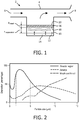
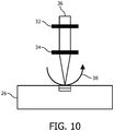
- the nebuliser 2 comprises a nebulisation chamber 10 between the inlet 6 and outlet 8 for storing a liquid 12, for example a medication or drug, to be nebulised (i.e. to be turned into a fine mist or spray).
- a liquid 12 for example a medication or drug
- the nebuliser 2 is configured such that the fine droplets of liquid 12 combine with the air drawn through the nebuliser 2 when the user inhales to deliver a dose of the medication or drug to the user.
- the nebuliser 2 may also comprise a reservoir that holds further liquid 12 to be nebulised and that is connected to the nebulisation chamber 10 so that the required amount of liquid 12 is maintained in the nebulisation chamber 10.
- the treatment time is mainly determined by the mass flow rate of the droplets generated by the nebuliser.
- treatment time can be up to several hours with currently available nebulisers.
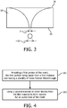
- the aerosol droplet size of the medicine In order for a medicine to be therapeutically effective when inhaled, and in particular for the medicine to be deposited in the lungs, the aerosol droplet size of the medicine must be within a narrow therapeutic range. The size of the droplets determines in which part of the lungs the medicine is deposited.
- the graph in Figure 2 shows how particle size affects the percentage deposition in the mouth and throat, the airways and the alveolar region.
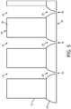
- the size of the droplets formed by the mesh is determined by the exit diameter of the nozzle (i.e. the diameter of the nozzle on the side of the mesh that droplets emerge - i.e. the outlet side 20 of the mesh 16 in the nebuliser 2 of Figure 1 ).
- the droplet diameter is roughly twice the exit diameter of the nozzle d as shown in Figure 3 . This means that a mesh 16 should typically have nozzles with an average exit diameter of 2.5 ⁇ m.
- every nozzle creates a single droplet during each cycle of the actuator 14.
- bigger droplets will result in a higher mass flow out of the nebuliser 2.
- the product to product variation of aerosol mass flow rate at a certain actuator vibration frequency should be low. Specifying a limit on this output variation thus has an implication for the acceptable variation in the nozzle exit diameter.
- the aerosol output in terms of grams per minute of liquid is 1.64 (90%) standard deviations within the specification limit.
- ⁇ drop 2 c 2 ⁇ nozzle 2 .
- this mass per unit area of the mesh 16 can normally only be achieved by forming the mesh 16 from a high density metal such as stainless steel, platinum or nickel palladium due to the additional constraint that the thickness of the mesh 16 should be small.
- a mesh that comprises a hybrid geometry in which the useful properties from two different types of material are combined to form the mesh.
- part of the mesh is made from a first material that provides the required mass per unit area of the mesh, and another part of the mesh is made from a second material (having a lower density than the first material) that is used to form the nozzles having the required exit diameter.
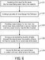
- a mesh for use in forming droplets of liquid in a nebuliser comprising a first portion made of a first material having a plurality of holes passing therethrough; and a second portion made of a second material that is in contact with the first portion, the second portion having a corresponding plurality of holes passing therethrough, the plurality of holes in the second portion forming nozzles for an outlet side of the mesh; wherein the first material has a higher density than the second material.
- the plurality of holes in the first portion made of the first material are provided with a first hole geometry having a first opening size.
- the plurality of holes in the second portion made of the second material are provided with a second hole geometry having a second opening size.
- the second opening size is smaller than the first opening size.
- the plurality of the holes in the first portion provide first supply openings, and the plurality of holes in the second portion provide the nozzles as second outlet openings that are arranged stream-downwards from the first supply openings.
- the first material can be a metal or a metal alloy.
- the first material can be stainless steel, platinum, cobalt, gold, tungsten or nickel palladium.
- the layer or plate of the second material is bonded or attached to the layer or plate of the first material.
- the second portion comprises second material located in the holes of the first portion.
- the first portion preferably has sufficient mass to create a resonant cavity in the nebuliser.
- the step of forming a plurality of holes through the first portion comprises using laser drilling.
- the step of providing a first portion comprises using electro formation.
- the step of using a second portion made of the second material having the plurality of holes formed therethrough comprises:
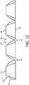
- the second portion provides transition portions between the inlet openings and the outlet openings. Further, the outlet openings are smaller than the inlet openings.
- the second openings forming the nozzles are provided having a tapered cross-section with a decreasing width in flowing direction; and, in step b), the second material is provided with an increasing material thickness forming the nozzle openings.
- step a) the plurality of the holes in the first portion provides first supply openings.
- step b) the plurality of holes in the second portion provides the nozzles as second outlet openings that are arranged stream-downwards from the first supply openings.
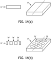
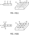
- the first material is provided as a layer or plate comprising the plurality of holes; and the second material is provided as a plurality of inlays that are least partly located in the holes of the first portion, each inlay at partly filling one of the holes in the first material, and having the nozzles formed in the second material.
- Figure 4 also shows further aspects as options of the method.
- step 101 can depend on the material the first portion is made of.
- step 101 can comprise providing a stainless steel layer or sheet and using laser-drilling to form the holes.
- Electroplating is a process that uses electrical current to reduce dissolved metal cations so that they form a coherent metal coating on an electrode.
- Electroforming uses electroplating to build structures with particular shapes on a substrate electrode, which is then separated from the electrode.
- a metal layer is grown on the substrate electrode, and using a non conductive layer like a polymer resist, areas can be selected that are shielded off from the metal growth.
- a metal structure is grown that has holes filled with non-conductive material, which is then removed to open up the holes to provide first portion.
- the thickness is in the range of 5 to 20 ⁇ m.
- materials having a density greater than 0.8 g/cm 3 and/or less than 3 g/cm 3 are suitable for use in forming the second portion of the mesh 16.
- materials having a density in the range of 0.8 to 3 g/cm 3 are used for forming the second portion of the mesh 16.
- step 103 Different ways of implementing step 103 will be described in more detail below.
- the step of using a second portion made of the second material having the plurality of holes formed therethrough comprises:
- step a) the plurality of the holes in the first portion provides first supply openings.
- the nozzles 28 in the second portion 26 are formed such that their diameter narrows from generally the same diameter as the holes 24 at the interface side (i.e. the side opposite the inlet side 18) of the first portion 22 to the desired exit diameter at the outlet side 20 of the mesh 16.
- the exit of the nozzles 28 is denoted 30 in Figure 5 .
- the profile of each nozzle 28 can taper to the desired diameter for the nozzle exit 30 in a linear or non-linear fashion (so producing a nozzle 28 with a straight or curved profile).
Claims (15)
- Netz (16, 16') zur Verwendung bei der Bildung von Flüssigkeitströpfchen in einem Zerstäuber, wobei das Netz Folgendes umfasst:- einen ersten Abschnitt (22, 22') aus einem ersten Material mit einer Vielzahl von hindurchführenden Löchern (24, 24'); und- einen zweiten Abschnitt (26, 26') aus einem zweiten Material in Kontakt mit dem ersten Abschnitt, wobei der zweite Abschnitt eine entsprechende Vielzahl von hindurchführenden Löchern aufweist, wobei die Vielzahl von Löchern in dem zweiten Abschnitt Düsen (28, 28') für eine Auslassseite (20, 20') des Netzes bilden;wobei das erste Material eine höhere Dichte aufweist als das zweite Material;
dadurch gekennzeichnet, dass die Vielzahl von Löchern in dem ersten Abschnitt aus dem ersten Material erste Öffnungen sind, die Einlassöffnungen des Netzes bilden;wobei die Vielzahl von Löchern in dem zweiten Abschnitt aus dem zweiten Material zweite Öffnungen sind, die Düsen mit Auslassöffnungen des Netzes bilden;wobei der zweite Abschnitt Übergangsabschnitte zwischen den Einlassöffnungen und den Auslassöffnungen bereitstellt; undwobei die Auslassöffnungen kleiner sind als die Einlassöffnungen. - Netz nach Anspruch 1,wobei die zweiten Öffnungen, die die Düsen bilden, einen sich verjüngenden Querschnitt mit einer abnehmenden Breite in Flussrichtung aufweisen;wobei das zweite Material mit einer zunehmenden Materialdicke zum Bilden der Düsenöffnungen bereitgestellt ist.
- Netz nach Anspruch 1 oder 2,wobei die Vielzahl von Löchern in dem ersten Abschnitt aus dem ersten Material mit einer ersten Lochgeometrie mit einer ersten Öffnungsgröße bereitgestellt werden;wobei die Vielzahl von Löchern in dem zweiten Abschnitt aus dem zweiten Material mit einer zweiten Lochgeometrie mit einer zweiten Öffnungsgröße bereitgestellt werden;wobei die zweite Öffnungsgröße kleiner ist als die erste Öffnungsgröße; undwobei die Vielzahl von Löchern in dem ersten Abschnitt erste Zuführungsöffnungen bereitstellen und die Vielzahl von Löchern in dem zweiten Abschnitt die Düsen als zweite Auslassöffnungen bereitstellen, die stromabwärts von den ersten Zuführungsöffnungen angeordnet sind.
- Netz nach einem der vorhergehenden Ansprüche,wobei das erste Material ein Material mit einer Dichte ist, die größer als 8 g/cm3 und/oder kleiner als 22 g/cm3 ist; und/oderwobei das zweite Material ein Material mit einer Dichte ist, die größer als 0,8 g/cm3 und/oder kleiner als 3 g/cm3 ist.
- Netz nach einem der vorhergehenden Ansprüche,
wobei vorgesehen ist, dassi) das erste Material ein Metall oder eine Metalllegierung ist;
wobei vorzugsweise das erste Material Edelstahl, Platin, Kobalt, Gold, Wolfram oder Nickelpalladium ist; und/oderii) das zweite Material Silikon, ein Polymer oder ein Epoxid ist;
wobei vorzugsweise das zweite Material Polycarbonat, Polyimid oder Epo-tek® 353ND ist. - Netz nach einem der vorhergehenden Ansprüche,
wobei die Vielzahl von Löchern in dem zweiten Abschnitt einen Durchmesser haben, der sich von einem Durchmesser, der im Allgemeinen der gleiche ist wie der Durchmesser der Löcher in dem ersten Abschnitt, auf der Auslassseite des Netzes zu einem kleineren Durchmesser verjüngt, der innerhalb eines vorgegebenen Bereichs liegt. - Netz nach einem der vorhergehenden Ansprüche,wobei das erste Material als eine Schicht oder Platte umfassend die Vielzahl von Löchern bereitgestellt ist und das zweite Material als eine Vielzahl von Einlagen bereitgestellt ist, die sich zumindest teilweise in den Löchern des ersten Abschnitts befinden, wobei jede Einlage eines der Löcher in dem ersten Material zumindest teilweise füllt, und die in dem zweiten Material ausgebildete Düsen aufweisen; und/oderwobei das erste Material als einer erste Schicht oder Platte umfassend die Vielzahl von Löchern bereitgestellt ist und das zweite Material als ein zweite Schicht oder Platte bereitgestellt ist, in der die Düsen ausgebildet sind.
- Netz nach einem der vorhergehenden Ansprüche,wobei der erste Abschnitt eine ausreichende Masse aufweist, um einen Resonanzhohlraum in dem Zerstäuber zu bilden; und/oderwobei der erste Abschnitt eine Masse pro Einheitsfläche von mindestens 0,04 Gramm/cm2 aufweist.
- Zerstäuber, umfassend einen Körper mit einem Einlass und einem Auslass, der so angeordnet ist, dass wenn ein Benutzer des Zerstäubers durch den Auslass einatmet, Luft über den Einlass und Auslass in und durch den Zerstäuber und in den Körper des Benutzers gesogen wird;wobei der Auslass in Form eines Mundstücks oder einer Gesichts- oder Nasenmaske oder in einer Form bereitgestellt ist, die sich zur Verbindung mit einem separat austauchbaren Mundstück oder einer separat austauschbaren Gesichts- oder Nasenmaske geeignet;ferner umfassend eine Zerstäubungskammer zwischen dem Einlass und dem Auslass zum Aufbewahren einer Flüssigkeit; undwobei der Zerstäuber mit einem Netz nach einem der vorhergehenden Ansprüche versehen ist, sodass sich die feinen Flüssigkeitströpfchen mit der durch den Zerstäuber gesogenen Luft kombinieren, wenn der Benutzer einatmet, um dem Benutzer eine Dosis des Medikaments oder Arzneimittels zu verabreichen.
- Verfahren zur Herstellung eines Netzes zur Verwendung bei der Bildung von Flüssigkeitströpfchen in einem Zerstäuber, wobei das Verfahren Folgendes umfasst:a) Bereitstellen (101) eines ersten Abschnitts aus einem ersten Material mit einer Vielzahl von hindurchführenden Löchern;b) Verwenden (103) eines zweiten Abschnitts aus einem zweiten Material, das eine geringere Dichte als das erste Material hat, um Düsen für eine Auslassseite des Netzes zu bilden, wobei der zweite Abschnitt in Kontakt mit dem ersten Abschnitt platziert ist, wobei der zweite Abschnitt eine entsprechende Vielzahl von hindurchführenden Löchern aufweist;wobei der Schritt des Bereitstellens eines ersten Abschnitts aus einem ersten Material mit der Vielzahl von hindurchführenden Löchern Folgendes umfasst:- Bereitstellen der Vielzahl von Löchern in dem ersten Abschnitt aus dem ersten Material als erste Öffnungen, die Einlassöffnungen des Netzes bilden;wobei der Schritt des Verwendens eines zweiten Abschnitts aus dem zweiten Material mit der Vielzahl von hindurchführenden Löchern Folgendes umfasst:- Bereitstellen der Vielzahl von Löchern in dem zweiten Abschnitt aus dem zweiten Material als zweite Öffnungen, die Düsen mit Auslassöffnungen des Netzes bilden;wobei der zweite Abschnitt Übergangsabschnitte zwischen den Einlassöffnungen und den Auslassöffnungen bereitstellt; und
wobei die Auslassöffnungen kleiner sind als die Einlassöffnungen. - Verfahren nach Anspruch 10,
wobei der Schritt des Bereitstellens eines ersten Abschnitts aus dem ersten Material mit der Vielzahl von hindurchführenden Löchern Folgendes umfasst:a1) Bereitstellen eines ersten Abschnitts aus dem ersten Material; unda2) Bilden einer Vielzahl von Löchern durch den ersten Abschnitt. - Verfahren nach Anspruch 10 oder 11,
wobei Folgendes vorgesehen ist:i) in Schritt b) werden die zweiten Öffnungen, die die Düsen bilden, mit einem sich verjüngenden Querschnitt mit einer abnehmenden Breite in Flussrichtung bereitgestellt;
wobei in Schritt b) das zweite Material mit einer zunehmenden Materialdicke zum Bilden der Düsenöffnungen bereitgestellt wird; und/oderii) in Schritt a) werden die Vielzahl von Öffnungen in dem ersten Abschnitt aus dem ersten Material mit einer ersten Lochgeometrie mit einer ersten Öffnungsgröße bereitgestellt;wobei in Schritt b) die Vielzahl von Löchern in dem zweiten Abschnitt aus dem zweiten Material mit einer zweiten Lochgeometrie mit einer zweiten Öffnungsgröße bereitgestellt werden; wobei die zweite Öffnungsgröße kleiner ist als die erste Öffnungsgröße;wobei in Schritt a) die Vielzahl von Löchern in dem ersten Abschnitt erste Zuführungsöffnungen bereitstellen; undwobei in Schritt b) die Vielzahl von Löchern in dem zweiten Abschnitt die Düsen als zweite Auslassöffnungen bereitstellen, die stromabwärts von den ersten Zuführungsöffnungen angeordnet sind. - Verfahren nach einem der Ansprüche 10 bis 12,
wobei der Schritt des Bereitstellens eines ersten Abschnitts das Bereitstellen einer Schicht oder Platte aus dem ersten Material umfasst. - Verfahren nach Anspruch 13,wobei das erste Material als eine Schicht oder Platte umfassend die Vielzahl von Löchern bereitgestellt wird; undwobei das zweite Material als eine Vielzahl von Einlagen bereitgestellt wird, die sich zumindest teilweise in den Löchern des ersten Abschnitts befinden, wobei jede Einlage eines der Löcher in dem ersten Material zumindest teilweise füllt, und die in dem zweiten Material ausgebildete Düsen aufweisen.
- Verfahren nach einem der Ansprüche 10 bis 14,
wobei der Schritt des Verwendens eines zweiten Abschnitts zum Bilden von Düsen für eine Auslassseite des Netzes Folgendes umfasst:b1) Bereitstellen einer Schicht oder Platte aus dem zweiten Material;b2) Bilden der übereinstimmenden Vielzahl von Löchern in dem zweiten Material; undb3) Bonden oder Anbringen des ersten Abschnitts an dem zweiten Abschnitt; und/oderwobei der Schritt des Verwendens eines zweiten Abschnitts zum Bilden von Düsen für eine Auslassseite des Netzes Folgendes umfasst:b4) Füllen der Vielzahl von Löchern in dem ersten Abschnitt mit dem zweiten Material; undb5) Bilden der Vielzahl von Düsen in dem zweiten Material.
Priority Applications (1)
| Application Number | Priority Date | Filing Date | Title |
|---|---|---|---|
| EP14766805.7A EP3024589B1 (de) | 2013-07-22 | 2014-07-15 | Netz zur verwendung in einem zerstäuber und verfahren zur herstellung davon |
Applications Claiming Priority (3)
| Application Number | Priority Date | Filing Date | Title |
|---|---|---|---|
| EP13306051 | 2013-07-22 | ||
| PCT/IB2014/063121 WO2015011608A1 (en) | 2013-07-22 | 2014-07-15 | A mesh for use in a nebuliser, and a method of manufacturing the same |
| EP14766805.7A EP3024589B1 (de) | 2013-07-22 | 2014-07-15 | Netz zur verwendung in einem zerstäuber und verfahren zur herstellung davon |
Publications (2)
| Publication Number | Publication Date |
|---|---|
| EP3024589A1 EP3024589A1 (de) | 2016-06-01 |
| EP3024589B1 true EP3024589B1 (de) | 2019-02-27 |
Family
ID=48906192
Family Applications (1)
| Application Number | Title | Priority Date | Filing Date |
|---|---|---|---|
| EP14766805.7A Active EP3024589B1 (de) | 2013-07-22 | 2014-07-15 | Netz zur verwendung in einem zerstäuber und verfahren zur herstellung davon |
Country Status (8)
| Country | Link |
|---|---|
| US (1) | US11357931B2 (de) |
| EP (1) | EP3024589B1 (de) |
| JP (1) | JP6408574B2 (de) |
| CN (1) | CN105408028B (de) |
| BR (1) | BR112016001153B1 (de) |
| ES (1) | ES2718678T3 (de) |
| RU (1) | RU2669082C2 (de) |
| WO (1) | WO2015011608A1 (de) |
Families Citing this family (6)
| Publication number | Priority date | Publication date | Assignee | Title |
|---|---|---|---|---|
| CN110621411B (zh) | 2017-05-31 | 2021-08-10 | 艾斯曲尔医疗公司 | 喷嘴装置及其制造方法 |
| CN111989005A (zh) | 2018-05-16 | 2020-11-24 | 菲利普莫里斯生产公司 | 雾化器及用于雾化器的网格 |
| JP7371311B2 (ja) * | 2018-05-24 | 2023-10-31 | 青島海爾洗滌電器有限公司 | 衣類処理装置及びその制御方法 |
| CN114144224A (zh) | 2019-03-26 | 2022-03-04 | 保科特纳洛克斯恩公司 | 药物合成物输送器械和方法 |
| WO2020198327A1 (en) * | 2019-03-26 | 2020-10-01 | Pocket Naloxone Corp. | Devices and methods for delivering pharmaceutical compositions |
| US11278709B1 (en) | 2021-03-12 | 2022-03-22 | Pocket Naloxone Corp. | Drug delivery device and methods for using same |
Family Cites Families (22)
| Publication number | Priority date | Publication date | Assignee | Title |
|---|---|---|---|---|
| SE349676B (de) | 1971-01-11 | 1972-10-02 | N Stemme | |
| JPS5912775A (ja) * | 1982-07-14 | 1984-01-23 | Matsushita Electric Ind Co Ltd | 霧化ポンプユニツト |
| JPS5952562A (ja) * | 1982-09-20 | 1984-03-27 | Matsushita Electric Ind Co Ltd | 霧化器 |
| JPS6054761A (ja) | 1983-09-02 | 1985-03-29 | Matsushita Electric Ind Co Ltd | 霧化装置 |
| US5133343A (en) * | 1985-08-09 | 1992-07-28 | Johnson Iv John J | Apparatus for supporting an inhaler |
| US5152456A (en) * | 1989-12-12 | 1992-10-06 | Bespak, Plc | Dispensing apparatus having a perforate outlet member and a vibrating device |
| US5487378A (en) * | 1990-12-17 | 1996-01-30 | Minnesota Mining And Manufacturing Company | Inhaler |
| US20090273633A1 (en) | 1997-07-15 | 2009-11-05 | Silverbrook Research Pty Ltd | Printhead Integrated Circuit With High Density Nozzle Array |
| US6425656B1 (en) | 1998-01-09 | 2002-07-30 | Seiko Epson Corporation | Ink-jet head, method of manufacture thereof, and ink-jet printer |
| US7677686B2 (en) | 1998-10-16 | 2010-03-16 | Silverbrook Research Pty Ltd | High nozzle density printhead ejecting low drop volumes |
| DE60122507T2 (de) | 2001-09-03 | 2007-04-05 | Microflow Engineering S.A. | Flüssigkeitstropfensprühvorrichtung |
| DE10348237A1 (de) | 2003-10-16 | 2005-05-19 | Pari GmbH Spezialisten für effektive Inhalation | Inhalationstherapievorrichtung mit einem Düsenvernebler |
| KR100561864B1 (ko) * | 2004-02-27 | 2006-03-17 | 삼성전자주식회사 | 잉크젯 프린트헤드의 노즐 플레이트 표면에 소수성코팅막을 형성하는 방법 |
| JP2005296737A (ja) * | 2004-04-07 | 2005-10-27 | Mikuni Corp | ビートプレート |
| US7347532B2 (en) | 2004-08-05 | 2008-03-25 | Fujifilm Dimatix, Inc. | Print head nozzle formation |
| RU2349392C2 (ru) | 2007-04-20 | 2009-03-20 | Общество с ограниченной ответственностью "Производственно-техническое и технологическое предприятие "Титан-А" (ООО "ПТ и ТП "Титан-А") | Ультразвуковой распылитель жидких препаратов различной вязкости |
| ITTO20080980A1 (it) | 2008-12-23 | 2010-06-24 | St Microelectronics Srl | Processo di fabbricazione di una membrana di ugelli integrata in tecnologia mems per un dispositivo di nebulizzazione e dispositivo di nebulizzazione che utilizza tale membrana |
| US9060715B2 (en) * | 2009-07-22 | 2015-06-23 | Koninklijke Philips N.V. | Nebulizer |
| US9623442B2 (en) * | 2009-11-24 | 2017-04-18 | Xerox Corporation | Process for thermally stable oleophobic low adhesion coating for inkjet printhead front face |
| US10314781B2 (en) | 2010-10-29 | 2019-06-11 | Koninklijke Philips N.V. | Nebulizer, a control unit for controlling the same, and a method of controlling a nebulizer |
| RU107026U1 (ru) | 2010-11-26 | 2011-08-10 | Евгений Иванович Евсюков | Устройство для ингаляций (варианты) |
| BR112013016671B1 (pt) * | 2010-12-28 | 2020-12-15 | Stamford Devices Ltd | Placa com abertura nebulizadora, malha vibratória do tipo nebulizador e método para a fabricação da dita placa |
-
2014
- 2014-07-15 JP JP2016528630A patent/JP6408574B2/ja active Active
- 2014-07-15 EP EP14766805.7A patent/EP3024589B1/de active Active
- 2014-07-15 RU RU2016105522A patent/RU2669082C2/ru active
- 2014-07-15 ES ES14766805T patent/ES2718678T3/es active Active
- 2014-07-15 US US14/906,371 patent/US11357931B2/en active Active
- 2014-07-15 CN CN201480041548.9A patent/CN105408028B/zh active Active
- 2014-07-15 BR BR112016001153-8A patent/BR112016001153B1/pt active IP Right Grant
- 2014-07-15 WO PCT/IB2014/063121 patent/WO2015011608A1/en active Application Filing
Non-Patent Citations (1)
| Title |
|---|
| None * |
Also Published As
| Publication number | Publication date |
|---|---|
| BR112016001153A2 (pt) | 2017-07-25 |
| JP2016525407A (ja) | 2016-08-25 |
| JP6408574B2 (ja) | 2018-10-17 |
| CN105408028A (zh) | 2016-03-16 |
| RU2016105522A (ru) | 2017-08-29 |
| US20160158464A1 (en) | 2016-06-09 |
| BR112016001153B1 (pt) | 2021-07-06 |
| CN105408028B (zh) | 2018-11-09 |
| ES2718678T3 (es) | 2019-07-03 |
| WO2015011608A1 (en) | 2015-01-29 |
| EP3024589A1 (de) | 2016-06-01 |
| US11357931B2 (en) | 2022-06-14 |
| RU2669082C2 (ru) | 2018-10-08 |
Similar Documents
| Publication | Publication Date | Title |
|---|---|---|
| EP3024589B1 (de) | Netz zur verwendung in einem zerstäuber und verfahren zur herstellung davon | |
| RU2593254C2 (ru) | Полученная фотолитографическим способом дырчатая пластина и способ ее изготовления | |
| JP4500477B2 (ja) | 改良されたアパーチャプレートならびにその構築および使用のための方法 | |
| EP2886185A1 (de) | Perforierte Membran und Verfahren zu ihrer Herstellung | |
| EP2744540B1 (de) | Zerstäuber sowie betriebsverfahren zu dessen steuerung | |
| US20090242663A1 (en) | Medical liquid droplet apparatus | |
| US11440030B2 (en) | Method for producing an aperture plate | |
| EP2841209B1 (de) | Ein zerstäuber und ein verfahren zur herstellung eines zerstäubers | |
| TWI338592B (en) | Nozzle plate of a spray apparatus and fabrication method thereof | |
| JP5157000B1 (ja) | 噴霧器用メッシュ | |
| EP4032619A1 (de) | Maschenzerstäuber mit porösem dünnem film und verfahren zur herstellung davon | |
| US9889261B2 (en) | Nebulizer mesh and production method thereof | |
| WO2014002770A1 (ja) | 液体噴霧装置 | |
| EP2947181B1 (de) | Verfahren zur herstellung einer lochplatte |
Legal Events
| Date | Code | Title | Description |
|---|---|---|---|
| PUAI | Public reference made under article 153(3) epc to a published international application that has entered the european phase |
Free format text: ORIGINAL CODE: 0009012 |
|
| 17P | Request for examination filed |
Effective date: 20160222 |
|
| AK | Designated contracting states |
Kind code of ref document: A1 Designated state(s): AL AT BE BG CH CY CZ DE DK EE ES FI FR GB GR HR HU IE IS IT LI LT LU LV MC MK MT NL NO PL PT RO RS SE SI SK SM TR |
|
| AX | Request for extension of the european patent |
Extension state: BA ME |
|
| DAX | Request for extension of the european patent (deleted) | ||
| GRAP | Despatch of communication of intention to grant a patent |
Free format text: ORIGINAL CODE: EPIDOSNIGR1 |
|
| STAA | Information on the status of an ep patent application or granted ep patent |
Free format text: STATUS: GRANT OF PATENT IS INTENDED |
|
| INTG | Intention to grant announced |
Effective date: 20180910 |
|
| GRAS | Grant fee paid |
Free format text: ORIGINAL CODE: EPIDOSNIGR3 |
|
| GRAA | (expected) grant |
Free format text: ORIGINAL CODE: 0009210 |
|
| STAA | Information on the status of an ep patent application or granted ep patent |
Free format text: STATUS: THE PATENT HAS BEEN GRANTED |
|
| AK | Designated contracting states |
Kind code of ref document: B1 Designated state(s): AL AT BE BG CH CY CZ DE DK EE ES FI FR GB GR HR HU IE IS IT LI LT LU LV MC MK MT NL NO PL PT RO RS SE SI SK SM TR |
|
| REG | Reference to a national code |
Ref country code: GB Ref legal event code: FG4D |
|
| REG | Reference to a national code |
Ref country code: CH Ref legal event code: EP |
|
| REG | Reference to a national code |
Ref country code: AT Ref legal event code: REF Ref document number: 1100564 Country of ref document: AT Kind code of ref document: T Effective date: 20190315 |
|
| REG | Reference to a national code |
Ref country code: IE Ref legal event code: FG4D |
|
| REG | Reference to a national code |
Ref country code: DE Ref legal event code: R096 Ref document number: 602014041864 Country of ref document: DE |
|
| REG | Reference to a national code |
Ref country code: NL Ref legal event code: FP |
|
| REG | Reference to a national code |
Ref country code: ES Ref legal event code: FG2A Ref document number: 2718678 Country of ref document: ES Kind code of ref document: T3 Effective date: 20190703 |
|
| REG | Reference to a national code |
Ref country code: LT Ref legal event code: MG4D |
|
| PG25 | Lapsed in a contracting state [announced via postgrant information from national office to epo] |
Ref country code: PT Free format text: LAPSE BECAUSE OF FAILURE TO SUBMIT A TRANSLATION OF THE DESCRIPTION OR TO PAY THE FEE WITHIN THE PRESCRIBED TIME-LIMIT Effective date: 20190627 Ref country code: FI Free format text: LAPSE BECAUSE OF FAILURE TO SUBMIT A TRANSLATION OF THE DESCRIPTION OR TO PAY THE FEE WITHIN THE PRESCRIBED TIME-LIMIT Effective date: 20190227 Ref country code: LT Free format text: LAPSE BECAUSE OF FAILURE TO SUBMIT A TRANSLATION OF THE DESCRIPTION OR TO PAY THE FEE WITHIN THE PRESCRIBED TIME-LIMIT Effective date: 20190227 Ref country code: NO Free format text: LAPSE BECAUSE OF FAILURE TO SUBMIT A TRANSLATION OF THE DESCRIPTION OR TO PAY THE FEE WITHIN THE PRESCRIBED TIME-LIMIT Effective date: 20190527 Ref country code: SE Free format text: LAPSE BECAUSE OF FAILURE TO SUBMIT A TRANSLATION OF THE DESCRIPTION OR TO PAY THE FEE WITHIN THE PRESCRIBED TIME-LIMIT Effective date: 20190227 |
|
| PG25 | Lapsed in a contracting state [announced via postgrant information from national office to epo] |
Ref country code: GR Free format text: LAPSE BECAUSE OF FAILURE TO SUBMIT A TRANSLATION OF THE DESCRIPTION OR TO PAY THE FEE WITHIN THE PRESCRIBED TIME-LIMIT Effective date: 20190528 Ref country code: IS Free format text: LAPSE BECAUSE OF FAILURE TO SUBMIT A TRANSLATION OF THE DESCRIPTION OR TO PAY THE FEE WITHIN THE PRESCRIBED TIME-LIMIT Effective date: 20190627 Ref country code: HR Free format text: LAPSE BECAUSE OF FAILURE TO SUBMIT A TRANSLATION OF THE DESCRIPTION OR TO PAY THE FEE WITHIN THE PRESCRIBED TIME-LIMIT Effective date: 20190227 Ref country code: LV Free format text: LAPSE BECAUSE OF FAILURE TO SUBMIT A TRANSLATION OF THE DESCRIPTION OR TO PAY THE FEE WITHIN THE PRESCRIBED TIME-LIMIT Effective date: 20190227 Ref country code: RS Free format text: LAPSE BECAUSE OF FAILURE TO SUBMIT A TRANSLATION OF THE DESCRIPTION OR TO PAY THE FEE WITHIN THE PRESCRIBED TIME-LIMIT Effective date: 20190227 Ref country code: BG Free format text: LAPSE BECAUSE OF FAILURE TO SUBMIT A TRANSLATION OF THE DESCRIPTION OR TO PAY THE FEE WITHIN THE PRESCRIBED TIME-LIMIT Effective date: 20190527 |
|
| REG | Reference to a national code |
Ref country code: AT Ref legal event code: MK05 Ref document number: 1100564 Country of ref document: AT Kind code of ref document: T Effective date: 20190227 |
|
| PG25 | Lapsed in a contracting state [announced via postgrant information from national office to epo] |
Ref country code: EE Free format text: LAPSE BECAUSE OF FAILURE TO SUBMIT A TRANSLATION OF THE DESCRIPTION OR TO PAY THE FEE WITHIN THE PRESCRIBED TIME-LIMIT Effective date: 20190227 Ref country code: CZ Free format text: LAPSE BECAUSE OF FAILURE TO SUBMIT A TRANSLATION OF THE DESCRIPTION OR TO PAY THE FEE WITHIN THE PRESCRIBED TIME-LIMIT Effective date: 20190227 Ref country code: RO Free format text: LAPSE BECAUSE OF FAILURE TO SUBMIT A TRANSLATION OF THE DESCRIPTION OR TO PAY THE FEE WITHIN THE PRESCRIBED TIME-LIMIT Effective date: 20190227 Ref country code: DK Free format text: LAPSE BECAUSE OF FAILURE TO SUBMIT A TRANSLATION OF THE DESCRIPTION OR TO PAY THE FEE WITHIN THE PRESCRIBED TIME-LIMIT Effective date: 20190227 Ref country code: AL Free format text: LAPSE BECAUSE OF FAILURE TO SUBMIT A TRANSLATION OF THE DESCRIPTION OR TO PAY THE FEE WITHIN THE PRESCRIBED TIME-LIMIT Effective date: 20190227 Ref country code: SK Free format text: LAPSE BECAUSE OF FAILURE TO SUBMIT A TRANSLATION OF THE DESCRIPTION OR TO PAY THE FEE WITHIN THE PRESCRIBED TIME-LIMIT Effective date: 20190227 |
|
| REG | Reference to a national code |
Ref country code: DE Ref legal event code: R097 Ref document number: 602014041864 Country of ref document: DE |
|
| PG25 | Lapsed in a contracting state [announced via postgrant information from national office to epo] |
Ref country code: PL Free format text: LAPSE BECAUSE OF FAILURE TO SUBMIT A TRANSLATION OF THE DESCRIPTION OR TO PAY THE FEE WITHIN THE PRESCRIBED TIME-LIMIT Effective date: 20190227 Ref country code: SM Free format text: LAPSE BECAUSE OF FAILURE TO SUBMIT A TRANSLATION OF THE DESCRIPTION OR TO PAY THE FEE WITHIN THE PRESCRIBED TIME-LIMIT Effective date: 20190227 |
|
| PG25 | Lapsed in a contracting state [announced via postgrant information from national office to epo] |
Ref country code: AT Free format text: LAPSE BECAUSE OF FAILURE TO SUBMIT A TRANSLATION OF THE DESCRIPTION OR TO PAY THE FEE WITHIN THE PRESCRIBED TIME-LIMIT Effective date: 20190227 |
|
| PLBE | No opposition filed within time limit |
Free format text: ORIGINAL CODE: 0009261 |
|
| STAA | Information on the status of an ep patent application or granted ep patent |
Free format text: STATUS: NO OPPOSITION FILED WITHIN TIME LIMIT |
|
| 26N | No opposition filed |
Effective date: 20191128 |
|
| PG25 | Lapsed in a contracting state [announced via postgrant information from national office to epo] |
Ref country code: SI Free format text: LAPSE BECAUSE OF FAILURE TO SUBMIT A TRANSLATION OF THE DESCRIPTION OR TO PAY THE FEE WITHIN THE PRESCRIBED TIME-LIMIT Effective date: 20190227 Ref country code: MC Free format text: LAPSE BECAUSE OF FAILURE TO SUBMIT A TRANSLATION OF THE DESCRIPTION OR TO PAY THE FEE WITHIN THE PRESCRIBED TIME-LIMIT Effective date: 20190227 |
|
| REG | Reference to a national code |
Ref country code: CH Ref legal event code: PL |
|
| PG25 | Lapsed in a contracting state [announced via postgrant information from national office to epo] |
Ref country code: TR Free format text: LAPSE BECAUSE OF FAILURE TO SUBMIT A TRANSLATION OF THE DESCRIPTION OR TO PAY THE FEE WITHIN THE PRESCRIBED TIME-LIMIT Effective date: 20190227 |
|
| REG | Reference to a national code |
Ref country code: BE Ref legal event code: MM Effective date: 20190731 |
|
| PG25 | Lapsed in a contracting state [announced via postgrant information from national office to epo] |
Ref country code: CH Free format text: LAPSE BECAUSE OF NON-PAYMENT OF DUE FEES Effective date: 20190731 Ref country code: LI Free format text: LAPSE BECAUSE OF NON-PAYMENT OF DUE FEES Effective date: 20190731 Ref country code: LU Free format text: LAPSE BECAUSE OF NON-PAYMENT OF DUE FEES Effective date: 20190715 Ref country code: BE Free format text: LAPSE BECAUSE OF NON-PAYMENT OF DUE FEES Effective date: 20190731 |
|
| PG25 | Lapsed in a contracting state [announced via postgrant information from national office to epo] |
Ref country code: IE Free format text: LAPSE BECAUSE OF NON-PAYMENT OF DUE FEES Effective date: 20190715 |
|
| PG25 | Lapsed in a contracting state [announced via postgrant information from national office to epo] |
Ref country code: CY Free format text: LAPSE BECAUSE OF FAILURE TO SUBMIT A TRANSLATION OF THE DESCRIPTION OR TO PAY THE FEE WITHIN THE PRESCRIBED TIME-LIMIT Effective date: 20190227 |
|
| PG25 | Lapsed in a contracting state [announced via postgrant information from national office to epo] |
Ref country code: MT Free format text: LAPSE BECAUSE OF FAILURE TO SUBMIT A TRANSLATION OF THE DESCRIPTION OR TO PAY THE FEE WITHIN THE PRESCRIBED TIME-LIMIT Effective date: 20190227 Ref country code: HU Free format text: LAPSE BECAUSE OF FAILURE TO SUBMIT A TRANSLATION OF THE DESCRIPTION OR TO PAY THE FEE WITHIN THE PRESCRIBED TIME-LIMIT; INVALID AB INITIO Effective date: 20140715 |
|
| PG25 | Lapsed in a contracting state [announced via postgrant information from national office to epo] |
Ref country code: MK Free format text: LAPSE BECAUSE OF FAILURE TO SUBMIT A TRANSLATION OF THE DESCRIPTION OR TO PAY THE FEE WITHIN THE PRESCRIBED TIME-LIMIT Effective date: 20190227 |
|
| PGFP | Annual fee paid to national office [announced via postgrant information from national office to epo] |
Ref country code: NL Payment date: 20230726 Year of fee payment: 10 |
|
| PGFP | Annual fee paid to national office [announced via postgrant information from national office to epo] |
Ref country code: IT Payment date: 20230721 Year of fee payment: 10 Ref country code: GB Payment date: 20230725 Year of fee payment: 10 Ref country code: ES Payment date: 20230816 Year of fee payment: 10 |
|
| PGFP | Annual fee paid to national office [announced via postgrant information from national office to epo] |
Ref country code: FR Payment date: 20230725 Year of fee payment: 10 Ref country code: DE Payment date: 20230726 Year of fee payment: 10 |