EP3024138A1 - Déphaseur et système de transmission équipé de celui-ci - Google Patents
Déphaseur et système de transmission équipé de celui-ci Download PDFInfo
- Publication number
- EP3024138A1 EP3024138A1 EP14825793.4A EP14825793A EP3024138A1 EP 3024138 A1 EP3024138 A1 EP 3024138A1 EP 14825793 A EP14825793 A EP 14825793A EP 3024138 A1 EP3024138 A1 EP 3024138A1
- Authority
- EP
- European Patent Office
- Prior art keywords
- phase shifter
- signal
- phase
- present
- exemplary embodiment
- Prior art date
- Legal status (The legal status is an assumption and is not a legal conclusion. Google has not performed a legal analysis and makes no representation as to the accuracy of the status listed.)
- Withdrawn
Links
Images


Classifications
-
- H—ELECTRICITY
- H03—ELECTRONIC CIRCUITRY
- H03D—DEMODULATION OR TRANSFERENCE OF MODULATION FROM ONE CARRIER TO ANOTHER
- H03D7/00—Transference of modulation from one carrier to another, e.g. frequency-changing
- H03D7/16—Multiple-frequency-changing
-
- H—ELECTRICITY
- H04—ELECTRIC COMMUNICATION TECHNIQUE
- H04B—TRANSMISSION
- H04B7/00—Radio transmission systems, i.e. using radiation field
- H04B7/02—Diversity systems; Multi-antenna system, i.e. transmission or reception using multiple antennas
- H04B7/04—Diversity systems; Multi-antenna system, i.e. transmission or reception using multiple antennas using two or more spaced independent antennas
- H04B7/06—Diversity systems; Multi-antenna system, i.e. transmission or reception using multiple antennas using two or more spaced independent antennas at the transmitting station
- H04B7/0613—Diversity systems; Multi-antenna system, i.e. transmission or reception using multiple antennas using two or more spaced independent antennas at the transmitting station using simultaneous transmission
- H04B7/0682—Diversity systems; Multi-antenna system, i.e. transmission or reception using multiple antennas using two or more spaced independent antennas at the transmitting station using simultaneous transmission using phase diversity (e.g. phase sweeping)
-
- H—ELECTRICITY
- H01—ELECTRIC ELEMENTS
- H01P—WAVEGUIDES; RESONATORS, LINES, OR OTHER DEVICES OF THE WAVEGUIDE TYPE
- H01P1/00—Auxiliary devices
- H01P1/18—Phase-shifters
- H01P1/182—Waveguide phase-shifters
-
- H—ELECTRICITY
- H01—ELECTRIC ELEMENTS
- H01P—WAVEGUIDES; RESONATORS, LINES, OR OTHER DEVICES OF THE WAVEGUIDE TYPE
- H01P1/00—Auxiliary devices
- H01P1/18—Phase-shifters
- H01P1/184—Strip line phase-shifters
-
- H—ELECTRICITY
- H01—ELECTRIC ELEMENTS
- H01P—WAVEGUIDES; RESONATORS, LINES, OR OTHER DEVICES OF THE WAVEGUIDE TYPE
- H01P5/00—Coupling devices of the waveguide type
- H01P5/02—Coupling devices of the waveguide type with invariable factor of coupling
-
- H—ELECTRICITY
- H01—ELECTRIC ELEMENTS
- H01Q—ANTENNAS, i.e. RADIO AERIALS
- H01Q21/00—Antenna arrays or systems
- H01Q21/30—Combinations of separate antenna units operating in different wavebands and connected to a common feeder system
-
- H—ELECTRICITY
- H01—ELECTRIC ELEMENTS
- H01Q—ANTENNAS, i.e. RADIO AERIALS
- H01Q3/00—Arrangements for changing or varying the orientation or the shape of the directional pattern of the waves radiated from an antenna or antenna system
- H01Q3/26—Arrangements for changing or varying the orientation or the shape of the directional pattern of the waves radiated from an antenna or antenna system varying the relative phase or relative amplitude of energisation between two or more active radiating elements; varying the distribution of energy across a radiating aperture
- H01Q3/30—Arrangements for changing or varying the orientation or the shape of the directional pattern of the waves radiated from an antenna or antenna system varying the relative phase or relative amplitude of energisation between two or more active radiating elements; varying the distribution of energy across a radiating aperture varying the relative phase between the radiating elements of an array
- H01Q3/34—Arrangements for changing or varying the orientation or the shape of the directional pattern of the waves radiated from an antenna or antenna system varying the relative phase or relative amplitude of energisation between two or more active radiating elements; varying the distribution of energy across a radiating aperture varying the relative phase between the radiating elements of an array by electrical means
-
- H—ELECTRICITY
- H04—ELECTRIC COMMUNICATION TECHNIQUE
- H04B—TRANSMISSION
- H04B1/00—Details of transmission systems, not covered by a single one of groups H04B3/00 - H04B13/00; Details of transmission systems not characterised by the medium used for transmission
- H04B1/02—Transmitters
- H04B1/04—Circuits
- H04B1/0475—Circuits with means for limiting noise, interference or distortion
Definitions
- the present disclosure relates to a phase shifter and a transmission system equipped with same.
- isolation between antennas requires improvement for increase in wireless transmission data speed (through-put) in a system transmitting and receiving data through frequencies of a plurality of bandwidths.
- a wireless (radio) transmission/receiving system uses a structure applied with an external antenna only, a structure applied with internal and external a ntennas and a structure applied with an internal antenna only.
- the structure ap plied with an external antenna only and the structure applied with internal and external antennas have no great problems of isolation between antennas, but va rious researches are being waged for improving isolation between antennas in t he structure applied with an internal antenna only.
- the technical subject to be solved by the present invention is to provide a phase shifter configured to minimize interference between first and second signals and to increase data transmission amount by shifting phases of the first and second signals to have a predetermined phase difference, and a system for transmitting (hereinafter referred to as "transmission system") using the same.
- a phase shifter comprising: an input unit through which a signal is inputted; a phase shifter having a partially-opened round shape and configured to shift a phase of the signal; and an output unit configured to output a phase-shifted signal by the phase shifter.
- the phase shifter may further comprise a first connector connected to a portion of a partially-opened part of the phase shifter and configured to connect the input unit and the phase shifter; and a second connector connected to the other portion of the partially-opened part of the phase shifter and configured to connect the output unit and the phase shifter.
- the phase shifted by the phase shifter may be determined by size of a diameter of the phase shifter.
- a transmission system using a phase shifter comprising: a first transmission unit configured to transmit a first signal through at least one first antenna; and a second transmission unit configured to transmit a second signal through at least one second antenna, wherein the second transmission unit includes a phase shifter configured to shift the second signal to have a phase difference from the first signal.
- the number of the phase shifter may correspond to that of the at least second antenna.
- the phase shifter may have one of ⁇ , 8, and ⁇ shapes.
- a frequency band of the first signal may correspond to that of the second signal.
- a frequency band of the first signal may be different from that of the second signal.
- Exemplary embodiments of the present invention have an advantageous effect in that data transmission speed can be improved by minimizing interference between two signals through orthogonal phase positioning of same frequency banded-signals.
- Another advantageous effect is that transmission speed of a wireless (radio) system using a plurality of antennas can be improved.
- Still another advantageous effect is that data transmission speed can be improved by minimizing interference between signals through shifting of orthogonal or different positioning of phases of a plurality of signals.
- FIG. 1 is a block diagram of a transmission system formed with a phase shifter according to an exemplary embodiment of the present invention.
- a system may include a first transmission unit (1) configured to transmit a signal of first frequency band, a second transmission unit (2) configured to transmit a signal of second frequency band, and a controller (3) configured to transmit a signal to the first and second transmission units (1, 2).
- the controller (3) may be embodied by an IC (Integrated Circuit) but detailed explanation thereto will be omitted here as it is irrelevant to the present invention.
- the first transmission unit (1) may include first and second antennas (11, 12) and a first amplifier (13). Although the exemplary embodiment of the present invention has illustrated an example including two antennas, the present invention is not limited thereto and the first transmission unit (1) may include a configuration formed with a plurality of antennas.
- a signal transmitted from the controller (3) may be amplified by the first amplifier (13) to be emitted through the first and second antennas (11, 12).
- the second transmission unit (2) may include a third antenna (21), a phase shifter (22) and a second amplifier (23).
- a third antenna 21
- a phase shifter (22) 2
- a second amplifier 23
- the exemplary embodiment of the present invention has illustrated an example including two antennas, the present invention is not limited thereto and the second transmission unit (2) may include a configuration formed with a plurality of antennas.
- each antenna is connected with a phase shifter (22).
- a signal transmitted from the controller (3) may be amplified by the second amplifier (23) to be shifted in phase by the phase shifter (22) according to an exemplary embodiment of the present invention and to be emitted through the third antenna (21).
- the phase shifter (22) may take one of ⁇ , 8, and ⁇ shapes.
- FIG. 2 is a schematic view of a phase shifter according to an exemplary embodiment of the present invention.
- the phase shifter (22) may include an input unit (22A) configured to input a signal, a phase shifter (22B) where a phase is shifted and outputted, and an output unit (22C) where a phase-shifted signal is outputted.
- a signal inputted through the input unit (22A) may be shifted in phase by the phase shifter (22B) and outputted through the output unit (22C).
- the phase shifter (22B) may have a predetermined size of diameter and take a partially opened round shape, and connected through the input unit (22A) and a first connector (22D), and connected through the output unit (22C) and a second connector (22E).
- the input unit (22A) and the output unit (22C) are illustrated to have a linear shape, but the present invention is not limited thereto, and the first connector (22D) and the second connector (22E) may be connected to an opened portion of the phase shifter (22B).
- the shifted phase may be determined by size of the phase shifter (22B). That is, when the diameter of the phase shifter (22B) is of a first size, the phase may be shifted to 90 degrees, and when the diameter of the phase shifter (22B) is of a second size, the phase may be shifted to 120 degrees. Furthermore, when the diameter of the phase shifter (22B) is of a third size, the phase may be shifted to 180 degrees. At this time, the first size may be smaller than the second size and the second size may be smaller than the third size.
- the number of antennas When the phase is shifted to 90 degrees, the number of antennas may be 3 to 4, when the phase is shifted to 120 degrees, the number of antennas may be 2 to 3, and when the phase is shifted to 180 degrees, the number of antennas may be 2.
- FIG. 3 is a schematic view of a shape of a phase shifter printed on a PCB according to an exemplary embodiment of the present invention.
- a signal inputted through the input unit (22A) of the phase shifter (22) through the second amplifier (23) may be phase-shifted by a predetermined angle by the phase shifter (22B), and a phase-shifted signal outputted through the output unit (22C) may be emitted through the third antenna (21).
- phase shifter is printed on a PCB
- present invention is not limited thereto, and the phase shifter may be variably configured in various transmission systems.
- the signals outputted to the first and second transmission units (1, 2) may be signals of same frequency band, or of mutually different frequency bands.
- a signal outputted through the first transmission unit (1) may be Wi-Fi signal, for example, and when the signal outputted through the second transmission unit (2) may be a Bluetooth® signal.
- Wi-Fi signal for example
- the signal outputted through the second transmission unit (2) may be a Bluetooth® signal
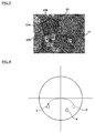
- FIG. 4 is a schematic view illustrating an operation of a phase shifter according to an exemplary embodiment of the present invention.
- phase (B) of one signal is orthogonally shifted to a phase (A) of another signal to allow phases of two signals to be mutually orthogonal, whereby data transmission speed can be enhanced.
- FIG. 5 is a schematic view illustrating a phase shifter that changes a phase by a size of 180 degrees according to an exemplary embodiment of the present invention
- FIG. 6 is a schematic view illustrating a phase shifter that changes a phase by a size of 90 degrees according to an exemplary embodiment of the present invention.
- the first transmission unit (1) includes two antennas (11, 12) and the second transmission unit (2) includes one antenna (21).
- D and E in FIG. 5 refer to signals transmitted through the first transmission unit (1), and F defines a signal transmitted through the second transmission unit (2). Furthermore, G and H in FIG. 6 define signals transmitted through the first transmission unit (1), and I refers to a signal transmitted through the second transmission unit (2).
- a signal inputted with the same phase is shifted to respectively 180 degrees and 90 degrees and transmitted through the first transmission unit (1) and a signal transmitted through the second transmission unit respectively have 180 degree and 90 degree phase differences.
- a transmission system formed with a phase shifter according to an exemplary embodiment of the present invention can improve the transmission speed by more than 10Mbps when Wi-Fi and Bluetooth signals are simultaneously transmitted.
- FIG. 7 are comparative views illustrating a case without a phase shifter according to exemplary embodiment of the present invention and a case with a phase shift according to exemplary embodiment of the present invention, where (a) of FIG.7A , (b) of FIG. 7C and (c) of FIG. 7E respectively illustrate phases of signal emitted through an antenna without a phase shifter, and (a) of FIG. 7B illustrates a case applied with a ⁇ type phase shifter, (b) of FIG. 7D illustrates a case applied with a 8 type phase shifter, and (c) of FIG. 7F illustrates a case applied with a ⁇ type phase shifter.
- 7B, 7D and 7F are changed in phase over 7A, 7C and 7E, whereby a signal transmitted through each antenna comes to have a predetermined phase difference to improve a data transmission speed.
- phase shifter according to an exemplary embodiment of the present invention has been described with reference to a number of limited illustrative embodiments thereof, it should be understood that numerous other modifications and embodiments can be devised by those skilled in the art that will fall within the spirit and scope of the principles of this disclosure. Therefore, it should be understood that the above-described embodiments are not limited by any of the details of the foregoing description and drawings, unless otherwise specified, but rather should be construed broadly within the scope as defined in the appended claims.
Landscapes
- Engineering & Computer Science (AREA)
- Computer Networks & Wireless Communication (AREA)
- Signal Processing (AREA)
- Power Engineering (AREA)
- Variable-Direction Aerials And Aerial Arrays (AREA)
- Transmitters (AREA)
- Waveguide Switches, Polarizers, And Phase Shifters (AREA)
- Details Of Aerials (AREA)
- Transceivers (AREA)
Applications Claiming Priority (2)
| Application Number | Priority Date | Filing Date | Title |
|---|---|---|---|
| KR1020130083611A KR102076525B1 (ko) | 2013-07-16 | 2013-07-16 | 위상변환기 및 이를 구비하는 송신 시스템 |
| PCT/KR2014/006442 WO2015009056A1 (fr) | 2013-07-16 | 2014-07-16 | Déphaseur et système de transmission équipé de celui-ci |
Publications (2)
| Publication Number | Publication Date |
|---|---|
| EP3024138A1 true EP3024138A1 (fr) | 2016-05-25 |
| EP3024138A4 EP3024138A4 (fr) | 2017-03-01 |
Family
ID=52346437
Family Applications (1)
| Application Number | Title | Priority Date | Filing Date |
|---|---|---|---|
| EP14825793.4A Withdrawn EP3024138A4 (fr) | 2013-07-16 | 2014-07-16 | Déphaseur et système de transmission équipé de celui-ci |
Country Status (7)
| Country | Link |
|---|---|
| US (1) | US20160373179A1 (fr) |
| EP (1) | EP3024138A4 (fr) |
| JP (1) | JP2016533073A (fr) |
| KR (1) | KR102076525B1 (fr) |
| CN (1) | CN105379108A (fr) |
| TW (1) | TW201509126A (fr) |
| WO (1) | WO2015009056A1 (fr) |
Families Citing this family (1)
| Publication number | Priority date | Publication date | Assignee | Title |
|---|---|---|---|---|
| KR20230014451A (ko) * | 2021-07-21 | 2023-01-30 | 엘지이노텍 주식회사 | 이종 복합 무선 통신 장치 |
Family Cites Families (15)
| Publication number | Priority date | Publication date | Assignee | Title |
|---|---|---|---|---|
| US4238745A (en) * | 1979-06-18 | 1980-12-09 | Rca Corporation | Phase shifter |
| CA2004857A1 (fr) * | 1988-12-21 | 1990-06-21 | Russell L. Holden | Circuit dephaseur en anneau |
| US5087922A (en) * | 1989-12-08 | 1992-02-11 | Hughes Aircraft Company | Multi-frequency band phased array antenna using coplanar dipole array with multiple feed ports |
| US5877659A (en) * | 1996-10-31 | 1999-03-02 | Northrop Grumman Corporation | 90° phase shifter apparatus and method using a directly coupled path and a switched path |
| KR20000075389A (ko) * | 1999-05-19 | 2000-12-15 | 김덕용 | 입력된 신호의 위상천이 및 감쇄를 위한 신호 처리장치 |
| CN1284797A (zh) * | 1999-08-16 | 2001-02-21 | Kmw株式会社 | 对所输入信号进行移相和对信号进行衰减的信号处理设备 |
| US6771931B2 (en) * | 2001-06-18 | 2004-08-03 | Intel Corporation | Method and an apparatus for passive interference cancellation |
| KR100562534B1 (ko) * | 2003-07-14 | 2006-03-22 | 주식회사 에이스테크놀로지 | 전력 분배 기능을 구비한 위상 가변기 |
| JP2007524323A (ja) * | 2004-02-25 | 2007-08-23 | コーニンクレッカ フィリップス エレクトロニクス エヌ ヴィ | アンテナアレイ |
| US7561006B2 (en) * | 2006-08-25 | 2009-07-14 | Banpil Photonics, Inc. | Low loss electrical delay line |
| JP4975105B2 (ja) * | 2006-10-03 | 2012-07-11 | ビーム ネットワークス リミテッド | 移相発振器およびフェーズド・アレイ・アンテナ |
| JP4808182B2 (ja) * | 2007-04-27 | 2011-11-02 | 株式会社エヌ・ティ・ティ・ドコモ | 無線通信装置、無線通信装置の給電方法 |
| CN101971413B (zh) * | 2008-02-25 | 2014-06-18 | 日本电业工作株式会社 | 多分支分配移相器 |
| US8456255B2 (en) * | 2010-05-04 | 2013-06-04 | Sparkmotion Inc. | Variable phase shifter comprising two finite coupling strips coupled to a branch line coupler |
| KR101075983B1 (ko) * | 2011-05-26 | 2011-10-21 | 주식회사 선우커뮤니케이션 | 안테나 위상 변위기 |
-
2013
- 2013-07-16 KR KR1020130083611A patent/KR102076525B1/ko active IP Right Grant
-
2014
- 2014-07-16 JP JP2016527930A patent/JP2016533073A/ja active Pending
- 2014-07-16 WO PCT/KR2014/006442 patent/WO2015009056A1/fr active Application Filing
- 2014-07-16 TW TW103124440A patent/TW201509126A/zh unknown
- 2014-07-16 US US14/900,308 patent/US20160373179A1/en not_active Abandoned
- 2014-07-16 CN CN201480039767.3A patent/CN105379108A/zh active Pending
- 2014-07-16 EP EP14825793.4A patent/EP3024138A4/fr not_active Withdrawn
Non-Patent Citations (1)
| Title |
|---|
| See references of WO2015009056A1 * |
Also Published As
| Publication number | Publication date |
|---|---|
| TW201509126A (zh) | 2015-03-01 |
| WO2015009056A1 (fr) | 2015-01-22 |
| EP3024138A4 (fr) | 2017-03-01 |
| KR102076525B1 (ko) | 2020-02-12 |
| KR20150009300A (ko) | 2015-01-26 |
| CN105379108A (zh) | 2016-03-02 |
| JP2016533073A (ja) | 2016-10-20 |
| US20160373179A1 (en) | 2016-12-22 |
Similar Documents
| Publication | Publication Date | Title |
|---|---|---|
| US9294178B2 (en) | Method and apparatus for transceiving for beam forming in wireless communication system | |
| US8742981B2 (en) | Microstrip coupler combining transmit-receive signal separation and differential to single ended conversion | |
| CN104079307A (zh) | 可消除干扰的电子装置 | |
| US10205233B2 (en) | Dual polarization antenna including isolation providing device | |
| EP2894792A1 (fr) | Module de communication sans fil | |
| KR20130074581A (ko) | 무선 통신 시스템에서의 수동 소자를 이용한 고주파 송수신 전치단 장치 | |
| JP2009044227A (ja) | 無線通信装置 | |
| US20060198429A1 (en) | Isolating circuit of transmitting and receiving paths in same frequency carrier | |
| EP3024138A1 (fr) | Déphaseur et système de transmission équipé de celui-ci | |
| JP2019140442A5 (fr) | ||
| US20080219391A1 (en) | Systems and Methods for Distributing a Clock Signal | |
| JP2013243487A (ja) | 車載アンテナ | |
| US20160190706A1 (en) | Antenna module | |
| CN107948947B (zh) | 用于车辆到x通信的通信设备 | |
| JP2013021406A (ja) | アンテナ装置 | |
| CN102782938A (zh) | 高频耦合器 | |
| US20210344124A1 (en) | Communication device | |
| US20200177228A1 (en) | Waveguide unit, waveguide device, and connection method | |
| US20170214148A1 (en) | Co-Frequency Full-Duplex Antenna Structure and Electronic Apparatus for Wireless Communications | |
| CN103762402A (zh) | 一种腔体滤波器 | |
| US8981865B2 (en) | First and second differential transmission lines where the second transmission line includes bent portions to surround the first transmission line | |
| EP4290680A1 (fr) | Appareil de communication à ondes millimétriques | |
| CN101409572B (zh) | 单或多系统信号匹配模块 | |
| KR200277969Y1 (ko) | 광대역 다중 송수신 결합장치 | |
| US20120289173A1 (en) | Interface of multi chip module |
Legal Events
| Date | Code | Title | Description |
|---|---|---|---|
| PUAI | Public reference made under article 153(3) epc to a published international application that has entered the european phase |
Free format text: ORIGINAL CODE: 0009012 |
|
| 17P | Request for examination filed |
Effective date: 20151222 |
|
| AK | Designated contracting states |
Kind code of ref document: A1 Designated state(s): AL AT BE BG CH CY CZ DE DK EE ES FI FR GB GR HR HU IE IS IT LI LT LU LV MC MK MT NL NO PL PT RO RS SE SI SK SM TR |
|
| AX | Request for extension of the european patent |
Extension state: BA ME |
|
| DAX | Request for extension of the european patent (deleted) | ||
| A4 | Supplementary search report drawn up and despatched |
Effective date: 20170201 |
|
| RIC1 | Information provided on ipc code assigned before grant |
Ipc: H01Q 21/30 20060101ALI20170126BHEP Ipc: H01Q 3/34 20060101AFI20170126BHEP Ipc: H01P 1/18 20060101ALI20170126BHEP |
|
| RAP1 | Party data changed (applicant data changed or rights of an application transferred) |
Owner name: LG INNOTEK CO., LTD. |
|
| STAA | Information on the status of an ep patent application or granted ep patent |
Free format text: STATUS: THE APPLICATION IS DEEMED TO BE WITHDRAWN |
|
| 18D | Application deemed to be withdrawn |
Effective date: 20170829 |