EP3023673A1 - Antriebsstrang und Adaptereinrichtung - Google Patents
Antriebsstrang und Adaptereinrichtung Download PDFInfo
- Publication number
- EP3023673A1 EP3023673A1 EP14194537.8A EP14194537A EP3023673A1 EP 3023673 A1 EP3023673 A1 EP 3023673A1 EP 14194537 A EP14194537 A EP 14194537A EP 3023673 A1 EP3023673 A1 EP 3023673A1
- Authority
- EP
- European Patent Office
- Prior art keywords
- housing
- adapter
- cooling cartridge
- transmission
- drive train
- Prior art date
- Legal status (The legal status is an assumption and is not a legal conclusion. Google has not performed a legal analysis and makes no representation as to the accuracy of the status listed.)
- Granted
Links
- 238000001816 cooling Methods 0.000 claims abstract description 72
- 230000005540 biological transmission Effects 0.000 claims abstract description 47
- 239000002826 coolant Substances 0.000 claims abstract description 26
- 230000008878 coupling Effects 0.000 claims abstract description 12
- 238000010168 coupling process Methods 0.000 claims abstract description 12
- 238000005859 coupling reaction Methods 0.000 claims abstract description 12
- 230000008901 benefit Effects 0.000 description 4
- 230000032683 aging Effects 0.000 description 2
- 238000010276 construction Methods 0.000 description 2
- 239000000498 cooling water Substances 0.000 description 2
- 239000003595 mist Substances 0.000 description 2
- 230000009467 reduction Effects 0.000 description 2
- 239000007921 spray Substances 0.000 description 2
- 230000004308 accommodation Effects 0.000 description 1
- 230000008859 change Effects 0.000 description 1
- 239000003795 chemical substances by application Substances 0.000 description 1
- 239000000284 extract Substances 0.000 description 1
- 238000009434 installation Methods 0.000 description 1
- 239000000463 material Substances 0.000 description 1
- 238000000034 method Methods 0.000 description 1
- 238000005192 partition Methods 0.000 description 1
- 230000008569 process Effects 0.000 description 1
- 238000007789 sealing Methods 0.000 description 1
Images

Classifications
-
- B—PERFORMING OPERATIONS; TRANSPORTING
- B60—VEHICLES IN GENERAL
- B60K—ARRANGEMENT OR MOUNTING OF PROPULSION UNITS OR OF TRANSMISSIONS IN VEHICLES; ARRANGEMENT OR MOUNTING OF PLURAL DIVERSE PRIME-MOVERS IN VEHICLES; AUXILIARY DRIVES FOR VEHICLES; INSTRUMENTATION OR DASHBOARDS FOR VEHICLES; ARRANGEMENTS IN CONNECTION WITH COOLING, AIR INTAKE, GAS EXHAUST OR FUEL SUPPLY OF PROPULSION UNITS IN VEHICLES
- B60K17/00—Arrangement or mounting of transmissions in vehicles
- B60K17/04—Arrangement or mounting of transmissions in vehicles characterised by arrangement, location, or kind of gearing
-
- F—MECHANICAL ENGINEERING; LIGHTING; HEATING; WEAPONS; BLASTING
- F16—ENGINEERING ELEMENTS AND UNITS; GENERAL MEASURES FOR PRODUCING AND MAINTAINING EFFECTIVE FUNCTIONING OF MACHINES OR INSTALLATIONS; THERMAL INSULATION IN GENERAL
- F16H—GEARING
- F16H57/00—General details of gearing
- F16H57/02—Gearboxes; Mounting gearing therein
- F16H57/025—Support of gearboxes, e.g. torque arms, or attachment to other devices
-
- B—PERFORMING OPERATIONS; TRANSPORTING
- B60—VEHICLES IN GENERAL
- B60K—ARRANGEMENT OR MOUNTING OF PROPULSION UNITS OR OF TRANSMISSIONS IN VEHICLES; ARRANGEMENT OR MOUNTING OF PLURAL DIVERSE PRIME-MOVERS IN VEHICLES; AUXILIARY DRIVES FOR VEHICLES; INSTRUMENTATION OR DASHBOARDS FOR VEHICLES; ARRANGEMENTS IN CONNECTION WITH COOLING, AIR INTAKE, GAS EXHAUST OR FUEL SUPPLY OF PROPULSION UNITS IN VEHICLES
- B60K17/00—Arrangement or mounting of transmissions in vehicles
- B60K17/04—Arrangement or mounting of transmissions in vehicles characterised by arrangement, location, or kind of gearing
- B60K17/06—Arrangement or mounting of transmissions in vehicles characterised by arrangement, location, or kind of gearing of change-speed gearing
-
- F—MECHANICAL ENGINEERING; LIGHTING; HEATING; WEAPONS; BLASTING
- F16—ENGINEERING ELEMENTS AND UNITS; GENERAL MEASURES FOR PRODUCING AND MAINTAINING EFFECTIVE FUNCTIONING OF MACHINES OR INSTALLATIONS; THERMAL INSULATION IN GENERAL
- F16H—GEARING
- F16H57/00—General details of gearing
- F16H57/02—Gearboxes; Mounting gearing therein
- F16H57/033—Series gearboxes, e.g. gearboxes based on the same design being available in different sizes or gearboxes using a combination of several standardised units
-
- F—MECHANICAL ENGINEERING; LIGHTING; HEATING; WEAPONS; BLASTING
- F16—ENGINEERING ELEMENTS AND UNITS; GENERAL MEASURES FOR PRODUCING AND MAINTAINING EFFECTIVE FUNCTIONING OF MACHINES OR INSTALLATIONS; THERMAL INSULATION IN GENERAL
- F16H—GEARING
- F16H57/00—General details of gearing
- F16H57/04—Features relating to lubrication or cooling or heating
- F16H57/0412—Cooling or heating; Control of temperature
- F16H57/0415—Air cooling or ventilation; Heat exchangers; Thermal insulations
- F16H57/0417—Heat exchangers adapted or integrated in the gearing
-
- F—MECHANICAL ENGINEERING; LIGHTING; HEATING; WEAPONS; BLASTING
- F16—ENGINEERING ELEMENTS AND UNITS; GENERAL MEASURES FOR PRODUCING AND MAINTAINING EFFECTIVE FUNCTIONING OF MACHINES OR INSTALLATIONS; THERMAL INSULATION IN GENERAL
- F16H—GEARING
- F16H57/00—General details of gearing
- F16H57/02—Gearboxes; Mounting gearing therein
- F16H2057/02034—Gearboxes combined or connected with electric machines
-
- F—MECHANICAL ENGINEERING; LIGHTING; HEATING; WEAPONS; BLASTING
- F16—ENGINEERING ELEMENTS AND UNITS; GENERAL MEASURES FOR PRODUCING AND MAINTAINING EFFECTIVE FUNCTIONING OF MACHINES OR INSTALLATIONS; THERMAL INSULATION IN GENERAL
- F16H—GEARING
- F16H57/00—General details of gearing
- F16H57/02—Gearboxes; Mounting gearing therein
- F16H2057/02039—Gearboxes for particular applications
- F16H2057/02069—Gearboxes for particular applications for industrial applications
- F16H2057/02073—Reduction gearboxes for industry
Definitions
- the present invention relates to a powertrain comprising a motor with a motor housing and a motor shaft, a transmission with a gear housing, a drive shaft and an output shaft, an arranged between the engine and the transmission adapter means which releasably connected to the motor housing and the gear housing adapter housing and a coupling device connecting the motor shaft and the drive shaft to each other, and at least one coolant supply to which at least one cooling cartridge is connected, wherein the cooling cartridge is arranged such that it cools existing oil within the transmission housing during normal operation of the drive train.
- the present invention relates to an adapter device with an adapter housing and a coupling device for connecting a motor shaft and a drive shaft of a transmission.
- Adapter devices are used to pair a predetermined engine with a predetermined transmission. With a plurality of such adapter devices corresponding powertrain series can be realized, in which a single motor with multiple gears and / or a single transmission can be connected to multiple engines or can.
- cooling cartridges known to dissipate heat from the transmission, which arise in particular by friction and splashing losses.
- MOTOX gearboxes from Siemens AG are equipped with cooling cartridges connected to a cooling water supply. The assembly of the cooling cartridges via a gearbox mounting cover, which is usually located in front of the slow-running gear stages of the transmission.
- the present invention provides a drive train of the type mentioned, which is characterized in that the cooling cartridge is attached to the adapter housing.
- the attachment of the cooling cartridge to the adapter housing is on the one hand to the advantage that sufficient space is available in the region of the adapter housing. Accordingly, the at least one cooling cartridge can constructively accommodate without much problems.
- cooling cartridges can be retrofitted to existing powertrains without much effort.
- the transmission is a reduction gear
- the arrangement of the cooling cartridge on the adapter housing on the other hand is advantageous in that the positioning of the cooling cartridge automatically takes place in the region of the high-speed input stage of the transmission, so that the cooling cartridge due to the stronger oil movement with very good efficiency.
- the cooling cartridge may be arranged so that it dips directly into the present in the lower region of the transmission housing oil sump. Alternatively, however, it can also be arranged such that it cools the spray oil or the oil mist.
- the adapter housing is preferably flanged to the motor housing and to the transmission housing. In this way, a stable construction of the drive train is ensured.
- the cooling cartridge is releasably attached to the adapter housing, so that it can be easily replaced or serviced.
- the cooling cartridge is provided with an external thread screwed into a threaded hole formed on the adapter housing, whereby a simple structure is achieved.
- At least one threaded plug is provided, which is designed such that it can be screwed into the threaded bore instead of the cooling cartridge. Accordingly, a powertrain with and without a cooling cartridge can optionally be realized. Alternatively, the cooling cartridge can also be connected to the process cooling of the system.
- the drive train according to the invention is a part of a transmission series, which has different engines, different transmissions and different adapter devices for selectively connecting the engines and transmissions.
- the cooling cartridge is attached to a wall of the adapter housing, through which the coupling device extends. Thanks to the good accessibility of such a wall, the cooling cartridge can be easily assembled and disassembled.
- the cooling cartridge may have a simple rod-shaped structure.
- the cooling cartridge is connected to a coolant supply to the engine. Since the motor is arranged directly adjacent to the adapter device, such a connection of the cooling cartridge to the coolant supply of the engine can be realized in a simple manner with little material expenditure.
- the present invention provides for the solution of the above-mentioned problem an adapter device of the type mentioned above, which is characterized in that it has at least one attached to the adapter housing cooling cartridge, which is designed in the intended mounted state of the adapter device to an oil sump of the transmission cool.
- the cooling cartridge is releasably attached to the adapter housing.
- the cooling cartridge in particular with an external thread be provided, which is screwed into a formed on the adapter housing threaded hole.
- the cooling cartridge is attached to a wall of the adapter housing, through which the coupling device extends.
- the adapter housing is preferably provided with coolant supply lines and coolant discharge lines extending through the housing wall, to which the cooling cartridge can be connected.
- the position of the coolant supply lines and the coolant outlets should be selected such that they are easily accessible.
- the figures show a drive train 1 according to an embodiment of the present invention having as main components a motor 2, a transmission 4 and an adapter device 5.
- the powertrain 1 may be part of a transmission series having a plurality of different engines, transmissions, and adapter devices that may be paired as needed.
- the motor 2 serves as a drive unit and comprises a motor housing 5 and a motor shaft, not shown.
- the transmission 3 is a reduction gear with a gear housing 6.
- the transmission 3 includes in a known manner a drive shaft and an output shaft, even if they are not shown here.
- the adapter device 4 is arranged between the engine 2 and the transmission 3. It has an adapter housing 7, which is flanged to the motor housing 5 and to the gear housing 6, wherein extending through the adapter housing 7, a coupling device 8, which connects the motor shaft with the drive shaft of the transmission 3.
- the coupling device 8 extends through a wall 9 of the adapter device 4, which defines a partition wall between the engine 2 and the transmission 3 and through which a threaded bore 10 extends eccentrically.
- a cooling cartridge 11 is provided.
- the cooling cartridge 11 comprises a cooling cartridge head 12, which has an external thread 13 and coolant connections not shown in detail.
- the coolant connections are fluidly connected to substantially U-shaped coolant lines 14, which extend outwardly from the cooling cartridge head 12.
- the cooling cartridge 11 is used starting from the side of the motor 2 through the provided in the wall 9 of the adapter device 4 threaded bore 10 and screwed with this. Accordingly, the coolant lines 14 project outward in the direction of the transmission 3.
- the position of the threaded hole 10 is chosen such that the coolant lines 14 completely immerse during normal operation of the drive train 1 in the oil sump of the transmission 3.
- the cooling cartridge 11 can also be arranged further above, so that it cools the spray oil or the oil mist.
- the coolant connections of the cooling cartridge 11 are connected to a coolant supply line 15 and a coolant discharge line 16, which extend through the adapter housing 7 and are connected to a coolant supply, not shown, of the motor 2.
- coolant is conducted through the coolant lines 14 of the cooling cartridge 11, for example in the form of cooling water.
- the coolant extracts heat from the oil of the transmission 3 and dissipates it.
- the direct heat transfer from oil to the cooling cartridge ensures optimum transmission cooling.
- the cooling capacity of the cooling cartridge 11 can be adjusted by the temperature of the supplied coolant and by the volume flow of the coolant. It should be understood that multiple cooling cartridges 11 can be provided should the cooling capacity of a single cooling cartridge 11 be insufficient.
- a threaded plug can be inserted into the provided in the wall 9 in the adapter housing 7 threaded bore 10.
- the cooling cartridge 11 is fastened to the adapter housing 7 of the adapter device 4 and thus to a position at which sufficient installation space is available. Accordingly, the accommodation of the cooling cartridge 11 can be realized structurally simple. In addition, adapter devices that have not been possible so far are provided with a cooling cartridge, be retrofitted in a simple manner. Another advantage of positioning the cooling cartridge 11 on the adapter housing 7 is that the cooling cartridge 11 is automatically positioned in the region of the high-speed input stage, so that the cooling cartridge 11 can be operated with a very good degree of efficiency. In addition, the cooling takes place primarily in the high-speed region of the transmission 3, so that the seal of the input shaft of the transmission undergoes a significant increase in life, since in addition to the high speed and the temperature contributes to sealing ring aging.
Landscapes
- Engineering & Computer Science (AREA)
- General Engineering & Computer Science (AREA)
- Mechanical Engineering (AREA)
- Chemical & Material Sciences (AREA)
- Combustion & Propulsion (AREA)
- Transportation (AREA)
- General Details Of Gearings (AREA)
Abstract
Description
- Die vorliegende Erfindung betrifft einen Antriebsstrang umfassend einen Motor mit einem Motorgehäuse und einer Motorwelle, ein Getriebe mit einem Getriebegehäuse, einer Antriebswelle und einer Abtriebswelle, eine zwischen dem Motor und dem Getriebe angeordnete Adaptereinrichtung, die ein mit dem Motorgehäuse und dem Getriebegehäuse lösbar verbundenes Adaptergehäuse und eine die Motorwelle und die Antriebswelle miteinander verbindende Kupplungseinrichtung aufweist, und zumindest eine Kühlmittelversorgung, an die wenigstens eine Kühlpatrone angeschlossen ist, wobei die Kühlpatrone derart angeordnet ist, dass sie während des bestimmungsgemäßen Betriebs des Antriebsstrangs innerhalb des Getriebegehäuses vorhandenes Öl kühlt. Ferner betrifft die vorliegende Erfindung eine Adaptereinrichtung mit einem Adaptergehäuse und einer Kupplungseinrichtung zum Verbinden einer Motorwelle und einer Antriebswelle eines Getriebes.
- Antriebsstränge und Adaptereinrichtungen der eingangs genannten Art sind im Stand der Technik in unterschiedlichsten Ausgestaltungen bekannt. Adaptereinrichtungen werden dazu eingesetzt, einen vorbestimmten Motor mit einem vorbestimmten Getriebe zu paaren. Mit einer Mehrzahl solcher Adaptereinrichtungen können entsprechend Antriebsstrangbaureihen realisiert werden, bei denen ein einzelner Motor mit mehreren Getrieben und/oder ein einzelnes Getriebe mit mehreren Motoren verbunden werden kann bzw. können. Ferner ist im Stand der Technik der Einsatz von so genannten Kühlpatronen bekannt, um Wärme aus dem Getriebe abzuführen, die insbesondere durch Reibungs- und Planschverluste entstehen. So sind beispielsweise MOTOX-Getriebe der Siemens AG mit an eine Kühlwasserversorgung angeschlossenen Kühlpatronen ausgestattet. Die Montage der Kühlpatronen erfolgt über einen Getriebemontagedeckel, der normalerweise vor den langsam laufenden Getriebestufen des Getriebes angeordnet ist.
- Ausgehend von diesem Stand der Technik ist es eine Aufgabe der vorliegenden Erfindung, einen Antriebsstrang und eine Adaptereinrichtung der eingangs genannten Art mit einem alternativen Aufbau zu schaffen.
- Zur Lösung dieser Aufgabe schafft die vorliegende Erfindung einen Antriebsstrang der eingangs genannten Art, der dadurch gekennzeichnet ist, dass die Kühlpatrone an dem Adaptergehäuse befestigt ist. Die Befestigung der Kühlpatrone an dem Adaptergehäuse ist zum einen dahingehend von Vorteil, dass im Bereich des Adaptergehäuses ausreichend Bauraum zur Verfügung steht. Entsprechend lässt sich die wenigstens eine Kühlpatrone konstruktiv ohne große Probleme unterbringen. Zudem können Kühlpatronen bei bestehenden Antriebssträngen auch ohne großen Aufwand nachgerüstet werden. Handelt es sich bei dem Getriebe um ein Untersetzungsgetriebe, ist die Anordnung der Kühlpatrone an dem Adaptergehäuse zum anderen dahingehend von Vorteil, dass die Positionierung der Kühlpatrone automatisch im Bereich der schnell laufenden Eingangsstufe des Getriebes erfolgt, so dass die Kühlpatrone aufgrund der stärkeren Ölbewegung mit sehr gutem Wirkungsgrad arbeiten kann. Die Kühlpatrone kann derart angeordnet sein, dass sie direkt in den im unteren Bereich des Getriebegehäuses vorhandenen Ölsumpf eintaucht. Alternativ kann sie aber auch derart angeordnet sein, dass sie das Spritzöl bzw. den Ölnebel kühlt.
- Das Adaptergehäuse ist bevorzugt an das Motorgehäuse und an das Getriebegehäuse angeflanscht. Auf diese Weise wird ein stabiler Aufbau des Antriebsstrangs gewährleistet.
- Vorteilhaft ist die Kühlpatrone lösbar an dem Adaptergehäuse befestigt, so dass diese problemlos ausgetauscht oder gewartet werden kann.
- Gemäß einer Ausgestaltung der vorliegenden Erfindung ist die Kühlpatrone mit einem Außengewinde versehen, das in eine an dem Adaptergehäuse ausgebildete Gewindebohrung geschraubt ist, wodurch ein einfacher Aufbau erzielt wird.
- Gemäß einer Variante der vorliegenden Erfindung ist zumindest ein Gewindestopfen vorgesehen, der derart ausgebildet ist, dass er anstelle der Kühlpatrone in die Gewindebohrung geschraubt werden kann. Entsprechend lässt sich wahlweise ein Antriebsstrang mit und ohne Kühlpatrone realisieren. Alternativ kann die Kühlpatrone aber auch an die Prozesskühlung der Anlage angeschlossen sein.
- Vorteilhaft stellt der erfindungsgemäße Antriebsstrang einen Teil einer Getriebebaureihe dar, die verschiedene Motoren, verschiedene Getriebe und verschiedene Adaptereinrichtungen zum wahlweisen Verbinden der Motoren und Getriebe aufweist.
- Vorteilhaft ist die Kühlpatrone an einer Wandung des Adaptergehäuses befestigt, durch die sich die Kupplungseinrichtung erstreckt. Dank der guten Zugänglichkeit einer solchen Wandung lässt sich die Kühlpatrone einfach montieren und demontieren. Darüber hinaus kann die Kühlpatrone einen einfachen stabförmigen Aufbau aufweisen.
- Vorteilhaft ist die Kühlpatrone an eine Kühlmittelversorgung des Motors angeschlossen. Da der Motor unmittelbar benachbart zu der Adaptereinrichtung angeordnet ist, lässt sich ein solcher Anschluss der Kühlpatrone an die Kühlmittelversorgung des Motors in einfacher Art und Weise mit wenig Materialaufwand realisieren.
- Ferner schafft die vorliegende Erfindung zur Lösung der eingangs genannten Aufgabe eine Adaptereinrichtung der eingangs genannten Art, die dadurch gekennzeichnet ist, dass diese zumindest eine an dem Adaptergehäuse befestigte Kühlpatrone aufweist, die dazu ausgelegt ist, im bestimmungsgemäß montierten Zustand der Adaptereinrichtung einen Ölsumpf des Getriebes zu kühlen.
- Bevorzugt ist die Kühlpatrone lösbar an dem Adaptergehäuse befestigt. So kann die Kühlpatrone insbesondere mit einem Außengewinde versehen sein, das in eine an dem Adaptergehäuse ausgebildete Gewindebohrung geschraubt ist.
- Vorteilhaft ist die Kühlpatrone an einer Wandung des Adaptergehäuses befestigt, durch die sich die Kupplungseinrichtung erstreckt.
- Bevorzugt ist das Adaptergehäuse mit sich durch die Gehäusewandung erstreckenden Kühlmittelzuleitungen und Kühlmittelableitungen versehen, an welche die Kühlpatrone angeschlossen werden kann. Die Position der Kühlmittelzuleitungen und der Kühlmittelableitungen sollte derart gewählt sein, dass diese gut zugänglich sind.
- Weitere Merkmale und Vorteile der vorliegenden Erfindung werden anhand der nachfolgenden Beschreibung eines Ausführungsbeispiels der vorliegenden Erfindung unter Bezugnahme auf die beiliegende Zeichnung deutlich. Darin ist
- Figur 1
- eine schematische perspektivische Ansicht eines Antriebsstrangs gemäß einer Ausführungsform der vorliegenden Erfindung;
- Figur 2
- eine perspektivische Ansicht eines Motors und einer Adaptereinrichtung des in
Figur 1 dargestellten Antriebsstrangs; und - Figur 3
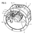
- eine perspektivische Ansicht der Adaptereinrichtung des in
Figur 1 dargestellten Antriebsstrangs, wenn diese von der Seite des Motors in Richtung des Getriebes betrachtet wird. - Die Figuren zeigen einen Antriebsstrang 1 gemäß einer Ausführungsform der vorliegenden Erfindung, der als Hauptkomponenten einen Motor 2, ein Getriebe 4 und eine Adaptereinrichtung 5 aufweist.
- Der Antriebsstrang 1 kann einen Teil einer Getriebebaureihe darstellen, die mehrere verschiedene Motoren, Getriebe und Adaptereinrichtungen aufweist, die bedarfsgerecht miteinander gepaart werden können.
- Der Motor 2 dient als Antriebseinheit und umfasst ein Motorgehäuse 5 und eine nicht näher dargestellte Motorwelle.
- Bei dem Getriebe 3 handelt es sich um ein Untersetzungsgetriebe mit einem Getriebegehäuse 6. Das Getriebe 3 umfasst in bekannter Weise eine Antriebswelle und eine Abtriebswelle, auch wenn diese vorliegend nicht dargestellt sind.
- Die Adaptereinrichtung 4 ist zwischen dem Motor 2 und dem Getriebe 3 angeordnet. Sie weist ein Adaptergehäuse 7 auf, das an das Motorgehäuse 5 und an das Getriebegehäuse 6 angeflanscht ist, wobei sich durch das Adaptergehäuse 7 eine Kupplungseinrichtung 8 erstreckt, welche die Motorwelle mit der Antriebswelle des Getriebes 3 verbindet. Die Kupplungseinrichtung 8 erstreckt sich durch eine Wandung 9 der Adaptereinrichtung 4, die eine Trennwand zwischen dem Motor 2 und dem Getriebe 3 definiert und durch die sich außermittig eine Gewindebohrung 10 erstreckt.
- Zur Abfuhr der während des Betriebs des Antriebsstrangs 1 im Getriebe 3 entstehenden Wärme, die insbesondere durch Reibungs- und Planschverluste erzeugt wird, ist eine Kühlpatrone 11 vorgesehen. Die Kühlpatrone 11 umfasst einen Kühlpatronenkopf 12, der ein Außengewinde 13 sowie nicht näher dargestellte Kühlmittelanschlüsse aufweist. Die Kühlmittelanschlüsse sind fluidtechnisch mit im Wesentlichen U-förmig ausgebildeten Kühlmittelleitungen 14 verbunden, die sich ausgehend von dem Kühlpatronenkopf 12 auswärts erstrecken. Die Kühlpatrone 11 ist ausgehend von der Seite des Motors 2 durch die in der Wandung 9 der Adaptereinrichtung 4 vorgesehene Gewindebohrung 10 eingesetzt und mit dieser verschraubt. Entsprechend stehen die Kühlmittelleitungen 14 auswärts in Richtung des Getriebes 3 vor. Die Position der Gewindebohrung 10 ist dabei derart gewählt, dass die Kühlmittelleitungen 14 während des bestimmungsgemäßen Betriebs des Antriebsstrangs 1 vollständig in den Ölsumpf des Getriebes 3 eintauchen. Alternativ kann die Kühlpatrone 11 aber auch weiter oberhalb angeordnet werden, so dass sie das Spritzöl bzw. den Ölnebel kühlt. Die Kühlmittelanschlüsse der Kühlpatrone 11 sind mit einer Kühlmittelzuleitung 15 und einer Kühlmittelableitung 16 verbunden, die sich durch das Adaptergehäuse 7 erstrecken und an eine nicht näher dargestellte Kühlmittelversorgung des Motors 2 angeschlossen sind.
- Während des Betriebs des Antriebsstrangs 1 wird Kühlmittel beispielsweise in Form von Kühlwasser durch die Kühlmittelleitungen 14 der Kühlpatrone 11 geleitet. Das Kühlmittel entzieht dem Öl des Getriebes 3 Wärme und führt diese ab. Durch die direkte Wärmeübertragung von Öl zur Kühlpatrone wird eine optimale Getriebekühlung erzielt. Die Kühlleistung der Kühlpatrone 11 lässt sich durch die Temperatur des zugeführten Kühlmittels sowie durch den Volumenstrom des Kühlmittels einstellen. Es sollte klar sein, dass mehrere Kühlpatronen 11 vorgesehen werden können, sollte die Kühlleistung einer einzelnen Kühlpatrone 11 nicht ausreichend sein.
- Für den Fall, dass gar keine Kühlung erforderlich ist, also die freie Konvektion zur Kühlung des Getriebes 3 ausreichend ist, kann anstelle der Kühlpatrone 11 ein Gewindestopfen in die in der Wandung 9 in das Adaptergehäuse 7 vorgesehene Gewindebohrung 10 eingesetzt werden.
- Dank des Einsatzes der Kühlpatrone 11 kann die Ölalterung gesenkt werden, was mit längeren Ölwechselfristen einhergeht. Ein wesentlicher Vorteil des zuvor beschriebenen Aufbaus des Antriebsstrangs 1 besteht darin, dass die Kühlpatrone 11 an dem Adaptergehäuse 7 der Adaptereinrichtung 4 und somit an einer Position befestigt ist, an der ausreichend Bauraum zur Verfügung steht. Entsprechend lässt sich die Unterbringung der Kühlpatrone 11 konstruktiv einfach realisieren. Darüber hinaus können auch Adaptereinrichtungen, die bislang nicht mit einer Kühlpatrone versehen sind, in einfacher Art und Weise nachgerüstet werden. Ein weiterer Vorteil der Positionierung der Kühlpatrone 11 an dem Adaptergehäuse 7 besteht darin, dass die Kühlpatrone 11 automatisch im Bereich der schnelllaufenden Eingangsstufe positioniert ist, so dass die Kühlpatrone 11 mit einem sehr guten Leistungsgrad betrieben werden kann. Darüber hinaus erfolgt die Kühlung vornehmlich in dem schnelllaufenden Bereich des Getriebes 3, so dass die Dichtung der Eingangswelle des Getriebes eine wesentliche Lebensdauersteigerung erfährt, da neben der hohen Drehzahl auch die Temperatur zur Dichtringalterung beiträgt.
- Obwohl die Erfindung im Detail durch das bevorzugte Ausführungsbeispiel näher illustriert und beschrieben wurde, so ist die Erfindung nicht durch die offenbarten Beispiele eingeschränkt und andere Variationen können vom Fachmann hieraus abgeleitet werden, ohne den Schutzumfang der Erfindung zu verlassen.
Claims (13)
- Antriebsstrang (1) umfassend einen Motor (2) mit einem Motorgehäuse (5) und einer Motorwelle, ein Getriebe (3) mit einem Getriebegehäuse (6), einer Antriebswelle und einer Abtriebswelle, eine zwischen dem Motor (2) und dem Getriebe (3) angeordnete Adaptereinrichtung (4), die ein mit dem Motorgehäuse (5) und dem Getriebegehäuse (6) lösbar verbundenes Adaptergehäuse (7) und eine die Motorwelle und die Antriebswelle miteinander verbindende Kupplungseinrichtung (8) aufweist, und zumindest eine Kühlmittelversorgung, an die wenigstens eine Kühlpatrone (11) angeschlossen ist, wobei die Kühlpatrone (11) derart angeordnet ist, dass sie während des bestimmungsgemäßen Betriebs des Antriebsstrangs (1) innerhalb des Getriebegehäuses (6) vorhandenes Öl kühlt, dadurch gekennzeichnet, dass die Kühlpatrone (11) an dem Adaptergehäuse (7) befestigt ist.
- Antriebsstrang (1) nach einem der vorhergehenden Ansprüche, dadurch gekennzeichnet, dass das Adaptergehäuse (7) an das Motorgehäuse (5) und an das Getriebegehäuse (6) angeflanscht ist.
- Antriebsstrang (1) nach einem der vorhergehenden Ansprüche, dadurch gekennzeichnet, dass die Kühlpatrone (11) lösbar an dem Adaptergehäuse (7) befestigt ist.
- Antriebsstrang (1) nach Anspruch 3, dadurch gekennzeichnet, dass die Kühlpatrone (11) mit einem Außengewinde (13) versehen ist, das in eine an dem Adaptergehäuse (7) ausgebildete Gewindebohrung (10) geschraubt ist.
- Antriebsstrang (1) nach Anspruch 4, dadurch gekennzeichnet, dass zumindest ein Gewindestopfen vorgesehen ist, der derart ausgebildet ist, dass er anstelle der Kühlpatrone (11) in die Gewindebohrung (10) geschraubt werden kann.
- Antriebsstrang (1) nach einem der vorhergehenden Ansprüche, dadurch gekennzeichnet, dass die Kühlpatrone (11) an einer Wandung des Adaptergehäuses (7) befestigt ist, durch die sich die Kupplungseinrichtung (8) erstreckt.
- Antriebsstrang (1) nach einem der vorhergehenden Ansprüche, dadurch gekennzeichnet, dass die Kühlpatrone (11) an eine Kühlmittelversorgung des Motors (2) angeschlossen ist.
- Antriebsstrang (1) nach einem der vorhergehenden Ansprüche, dadurch gekennzeichnet, dass dieser einen Teil einer Getriebebaureihe darstellt, die verschiedene Motoren, verschiedene Getriebe und verschiedene Kupplungseinrichtungen zum wahlweisen Verbinden der Motoren und Getriebe aufweist.
- Adaptereinrichtung (4) mit einem Adaptergehäuse (7) und einer Kupplungseinrichtung (8) zum Verbinden einer Motorwelle und einer Antriebswelle eines Getriebes (3), dadurch gekennzeichnet, dass die Adaptereinrichtung (4) zumindest eine an dem Adaptergehäuse (7) befestigte Kühlpatrone (11) aufweist, die dazu ausgelegt ist, im bestimmungsgemäß montierten Zustand der Adaptereinrichtung (4) einen Ölsumpf des Getriebes (3) zu kühlen.
- Adaptereinrichtung (4) nach Anspruch 9, dadurch gekennzeichnet, dass die Kühlpatrone (11) lösbar an dem Adaptergehäuse (7) befestigt ist.
- Adaptereinrichtung (4) nach Anspruch 10, dadurch gekennzeichnet, dass die Kühlpatrone (11) mit einem Außengewinde (13) versehen ist, das in eine an dem Adaptergehäuse (7) ausgebildete Gewindebohrung (10) geschraubt ist.
- Adaptereinrichtung (4) nach einem der Ansprüche 8 bis 11, dadurch gekennzeichnet, dass die Kühlpatrone (11) an einer Wandung (9) des Adaptergehäuses (7) befestigt ist, durch die sich die Kupplungseinrichtung (8) erstreckt.
- Adaptereinrichtung (4) nach einem der Ansprüche 9 bis 12, dadurch gekennzeichnet, dass das Adaptergehäuse (7) mit sich durch die Gehäusewandung erstreckenden Kühlmittelzuleitungen (15) und Kühlmittelableitungen (16) versehen ist.
Priority Applications (3)
| Application Number | Priority Date | Filing Date | Title |
|---|---|---|---|
| EP14194537.8A EP3023673B1 (de) | 2014-11-24 | 2014-11-24 | Antriebsstrang und Adaptereinrichtung |
| US14/949,329 US20160146329A1 (en) | 2014-11-24 | 2015-11-23 | Drive train and adapter device |
| CN201510815393.6A CN105620279B (zh) | 2014-11-24 | 2015-11-23 | 传动系和适配器装置 |
Applications Claiming Priority (1)
| Application Number | Priority Date | Filing Date | Title |
|---|---|---|---|
| EP14194537.8A EP3023673B1 (de) | 2014-11-24 | 2014-11-24 | Antriebsstrang und Adaptereinrichtung |
Publications (2)
| Publication Number | Publication Date |
|---|---|
| EP3023673A1 true EP3023673A1 (de) | 2016-05-25 |
| EP3023673B1 EP3023673B1 (de) | 2018-01-31 |
Family
ID=52003580
Family Applications (1)
| Application Number | Title | Priority Date | Filing Date |
|---|---|---|---|
| EP14194537.8A Active EP3023673B1 (de) | 2014-11-24 | 2014-11-24 | Antriebsstrang und Adaptereinrichtung |
Country Status (3)
| Country | Link |
|---|---|
| US (1) | US20160146329A1 (de) |
| EP (1) | EP3023673B1 (de) |
| CN (1) | CN105620279B (de) |
Families Citing this family (3)
| Publication number | Priority date | Publication date | Assignee | Title |
|---|---|---|---|---|
| CN107654627B (zh) * | 2017-09-29 | 2023-11-10 | 麦格纳动力总成(江西)有限公司 | 一种湿式双离合器自动变速器内置冷却系统 |
| KR200491811Y1 (ko) * | 2017-09-29 | 2020-06-09 | 시오우 링 쳉 | 차량 동력 전달 장치 |
| WO2020084990A1 (ja) * | 2018-10-26 | 2020-04-30 | ジヤトコ株式会社 | 動力伝達装置のハウジング部材 |
Citations (4)
| Publication number | Priority date | Publication date | Assignee | Title |
|---|---|---|---|---|
| JPS62126657U (de) * | 1986-02-04 | 1987-08-11 | ||
| JP2001253257A (ja) * | 2000-03-09 | 2001-09-18 | Fuji Heavy Ind Ltd | Atfクーラの取付構造 |
| DE102007024511A1 (de) * | 2007-05-24 | 2008-11-27 | Sew-Eurodrive Gmbh & Co. Kg | Wärmetauschmodul, Kühlpatrone, Getriebe, Getriebebaureihe und Verfahren zur Überwachung eines Getriebes |
| JP2010031981A (ja) * | 2008-07-30 | 2010-02-12 | Mazda Motor Corp | 変速機 |
Family Cites Families (9)
| Publication number | Priority date | Publication date | Assignee | Title |
|---|---|---|---|---|
| DE29603748U1 (de) * | 1996-02-29 | 1996-09-26 | Siemens Ag | Kraftfahrzeug-Antrieb mit einem Elektromotor |
| DE19637361C2 (de) * | 1996-09-13 | 1998-10-08 | Sew Eurodrive Gmbh & Co | Adapter und Adaptersystem zum Verbinden von Motoren mit Getrieben |
| EP1576713B1 (de) * | 2002-12-19 | 2009-09-02 | SEW-EURODRIVE GMBH & CO. | Adapter, getriebemotor und getriebemotor-baukasten |
| US20050066756A1 (en) * | 2003-09-30 | 2005-03-31 | Clare Patrick S. | System for securing a motor transversely to a gearbox |
| FR2866684B1 (fr) * | 2004-02-24 | 2007-05-11 | Renault Vehicules Ind | Ensemble de mecanique adaptation |
| US20090078082A1 (en) * | 2007-09-26 | 2009-03-26 | Gm Global Technology Operations, Inc. | Adapter Ring For Transmission Case To Engine Connection |
| DE102010042262A1 (de) * | 2010-10-11 | 2012-04-12 | Robert Bosch Gmbh | Elektronische Steuereinrichtung |
| EP2623821A1 (de) * | 2012-02-06 | 2013-08-07 | Siemens Aktiengesellschaft | Getriebegehäuse, Getriebeeinheit mit einem solchen Getriebegehäuse und Getriebemotor mit einer solchen Getriebeeinheit |
| EP2735774A1 (de) * | 2012-11-26 | 2014-05-28 | Siemens Aktiengesellschaft | Kupplungsadapter |
-
2014
- 2014-11-24 EP EP14194537.8A patent/EP3023673B1/de active Active
-
2015
- 2015-11-23 US US14/949,329 patent/US20160146329A1/en not_active Abandoned
- 2015-11-23 CN CN201510815393.6A patent/CN105620279B/zh active Active
Patent Citations (4)
| Publication number | Priority date | Publication date | Assignee | Title |
|---|---|---|---|---|
| JPS62126657U (de) * | 1986-02-04 | 1987-08-11 | ||
| JP2001253257A (ja) * | 2000-03-09 | 2001-09-18 | Fuji Heavy Ind Ltd | Atfクーラの取付構造 |
| DE102007024511A1 (de) * | 2007-05-24 | 2008-11-27 | Sew-Eurodrive Gmbh & Co. Kg | Wärmetauschmodul, Kühlpatrone, Getriebe, Getriebebaureihe und Verfahren zur Überwachung eines Getriebes |
| JP2010031981A (ja) * | 2008-07-30 | 2010-02-12 | Mazda Motor Corp | 変速機 |
Also Published As
| Publication number | Publication date |
|---|---|
| CN105620279B (zh) | 2018-12-04 |
| EP3023673B1 (de) | 2018-01-31 |
| CN105620279A (zh) | 2016-06-01 |
| US20160146329A1 (en) | 2016-05-26 |
Similar Documents
| Publication | Publication Date | Title |
|---|---|---|
| DE102007020453B4 (de) | Getriebe, Schmiermittel-Kreislaufsystem und Getriebebaureihe | |
| EP2126416B1 (de) | Getriebe mit ölkreislauf-verrohrung und getriebe- baureihe | |
| DE3209514C2 (de) | In sich geschlossene Getriebeanlage mit Druckschmierung | |
| DE10223927B4 (de) | Verkleidung für eine Pumpe in einem Schrägradgetriebe | |
| DE102012102798B4 (de) | Antriebseinheit mit Ölaustausch | |
| DE102012205757B4 (de) | Rotor für eine rotierende elektrische Maschine und Motor-Getriebe-Einheit | |
| DE102016114403B4 (de) | Zapfwellen-system für ein kraftfahrzeug, das der ausrückkupplung ölablass und drucköl bereitstellt | |
| DE102007004964B4 (de) | Getriebe mit Schmierölpumpe und Getriebe-Baureihe | |
| DE102019128957A1 (de) | Schmiermittelversorgungseinrichtung für ein Kraftfahrzeug, Verfahren zum Betreiben einer solchen Schmiermittelversorgungseinrichtung sowie Kraftfahrzeug mit einer solchen Schmiermittelversorgungseinrichtung | |
| EP2923120B1 (de) | Adapterbaugruppe | |
| DE102014011636A1 (de) | Ölzufuhrvorrichtung eines Fahrzeuggetriebes | |
| EP3023673B1 (de) | Antriebsstrang und Adaptereinrichtung | |
| DE102020203984B4 (de) | Ölversorgungssystem eines Fahrzeuggetriebes | |
| DE102015004991B3 (de) | Getriebe | |
| WO2014111250A1 (de) | Antrieb | |
| DE2148819C3 (de) | Kühlvorrichtung für eine Getriebeanordnung, insbesondere für den Antrieb von Gewinnungs- und Fördereinrichtungen für den Bergbau | |
| EP2394091B1 (de) | Tragelement mit einer antriebseinheit | |
| DE112019002167T5 (de) | Fahrzeugantriebseinheit | |
| DE102004032227A1 (de) | Schmierungsstruktur eines Handschaltgetriebes | |
| WO2022268370A1 (de) | Ölverteiler, achsantrieb und kraftfahrzeug | |
| DE102014208867A1 (de) | Integration einer Elektromotoreneinheit in ein Getriebegehäuse | |
| DE102016011436A1 (de) | Anordnung von Schrauben für einen Schraubenkompressor für ein Nutzfahrzeug | |
| DE102016207455A1 (de) | Schmiermittelleitschale und damit ausgestattetes Getriebe | |
| DE102016102096A1 (de) | Verzahnungskörper mit einer Schmiermittelzuführeinrichtung und Strahltriebwerk mit einem derartigen Verzahnungskörper | |
| WO2020260076A1 (de) | Retarder |
Legal Events
| Date | Code | Title | Description |
|---|---|---|---|
| AK | Designated contracting states |
Kind code of ref document: A1 Designated state(s): AL AT BE BG CH CY CZ DE DK EE ES FI FR GB GR HR HU IE IS IT LI LT LU LV MC MK MT NL NO PL PT RO RS SE SI SK SM TR |
|
| AX | Request for extension of the european patent |
Extension state: BA ME |
|
| PUAI | Public reference made under article 153(3) epc to a published international application that has entered the european phase |
Free format text: ORIGINAL CODE: 0009012 |
|
| 17P | Request for examination filed |
Effective date: 20160606 |
|
| RBV | Designated contracting states (corrected) |
Designated state(s): AL AT BE BG CH CY CZ DE DK EE ES FI FR GB GR HR HU IE IS IT LI LT LU LV MC MK MT NL NO PL PT RO RS SE SI SK SM TR |
|
| 17Q | First examination report despatched |
Effective date: 20170216 |
|
| RAP1 | Party data changed (applicant data changed or rights of an application transferred) |
Owner name: SIEMENS AKTIENGESELLSCHAFT |
|
| GRAP | Despatch of communication of intention to grant a patent |
Free format text: ORIGINAL CODE: EPIDOSNIGR1 |
|
| RIC1 | Information provided on ipc code assigned before grant |
Ipc: F16H 57/02 20120101ALN20170808BHEP Ipc: F16H 57/04 20100101AFI20170808BHEP Ipc: F16H 57/025 20120101ALI20170808BHEP Ipc: F16H 57/033 20120101ALI20170808BHEP |
|
| INTG | Intention to grant announced |
Effective date: 20170831 |
|
| GRAS | Grant fee paid |
Free format text: ORIGINAL CODE: EPIDOSNIGR3 |
|
| GRAA | (expected) grant |
Free format text: ORIGINAL CODE: 0009210 |
|
| AK | Designated contracting states |
Kind code of ref document: B1 Designated state(s): AL AT BE BG CH CY CZ DE DK EE ES FI FR GB GR HR HU IE IS IT LI LT LU LV MC MK MT NL NO PL PT RO RS SE SI SK SM TR |
|
| REG | Reference to a national code |
Ref country code: GB Ref legal event code: FG4D Free format text: NOT ENGLISH Ref country code: CH Ref legal event code: EP |
|
| REG | Reference to a national code |
Ref country code: AT Ref legal event code: REF Ref document number: 967688 Country of ref document: AT Kind code of ref document: T Effective date: 20180215 |
|
| REG | Reference to a national code |
Ref country code: IE Ref legal event code: FG4D Free format text: LANGUAGE OF EP DOCUMENT: GERMAN |
|
| REG | Reference to a national code |
Ref country code: DE Ref legal event code: R096 Ref document number: 502014007098 Country of ref document: DE |
|
| REG | Reference to a national code |
Ref country code: NL Ref legal event code: MP Effective date: 20180131 |
|
| REG | Reference to a national code |
Ref country code: LT Ref legal event code: MG4D |
|
| PG25 | Lapsed in a contracting state [announced via postgrant information from national office to epo] |
Ref country code: NL Free format text: LAPSE BECAUSE OF FAILURE TO SUBMIT A TRANSLATION OF THE DESCRIPTION OR TO PAY THE FEE WITHIN THE PRESCRIBED TIME-LIMIT Effective date: 20180131 Ref country code: LT Free format text: LAPSE BECAUSE OF FAILURE TO SUBMIT A TRANSLATION OF THE DESCRIPTION OR TO PAY THE FEE WITHIN THE PRESCRIBED TIME-LIMIT Effective date: 20180131 Ref country code: FI Free format text: LAPSE BECAUSE OF FAILURE TO SUBMIT A TRANSLATION OF THE DESCRIPTION OR TO PAY THE FEE WITHIN THE PRESCRIBED TIME-LIMIT Effective date: 20180131 Ref country code: NO Free format text: LAPSE BECAUSE OF FAILURE TO SUBMIT A TRANSLATION OF THE DESCRIPTION OR TO PAY THE FEE WITHIN THE PRESCRIBED TIME-LIMIT Effective date: 20180430 Ref country code: ES Free format text: LAPSE BECAUSE OF FAILURE TO SUBMIT A TRANSLATION OF THE DESCRIPTION OR TO PAY THE FEE WITHIN THE PRESCRIBED TIME-LIMIT Effective date: 20180131 Ref country code: HR Free format text: LAPSE BECAUSE OF FAILURE TO SUBMIT A TRANSLATION OF THE DESCRIPTION OR TO PAY THE FEE WITHIN THE PRESCRIBED TIME-LIMIT Effective date: 20180131 |
|
| PG25 | Lapsed in a contracting state [announced via postgrant information from national office to epo] |
Ref country code: SE Free format text: LAPSE BECAUSE OF FAILURE TO SUBMIT A TRANSLATION OF THE DESCRIPTION OR TO PAY THE FEE WITHIN THE PRESCRIBED TIME-LIMIT Effective date: 20180131 Ref country code: LV Free format text: LAPSE BECAUSE OF FAILURE TO SUBMIT A TRANSLATION OF THE DESCRIPTION OR TO PAY THE FEE WITHIN THE PRESCRIBED TIME-LIMIT Effective date: 20180131 Ref country code: RS Free format text: LAPSE BECAUSE OF FAILURE TO SUBMIT A TRANSLATION OF THE DESCRIPTION OR TO PAY THE FEE WITHIN THE PRESCRIBED TIME-LIMIT Effective date: 20180131 Ref country code: GR Free format text: LAPSE BECAUSE OF FAILURE TO SUBMIT A TRANSLATION OF THE DESCRIPTION OR TO PAY THE FEE WITHIN THE PRESCRIBED TIME-LIMIT Effective date: 20180501 Ref country code: IS Free format text: LAPSE BECAUSE OF FAILURE TO SUBMIT A TRANSLATION OF THE DESCRIPTION OR TO PAY THE FEE WITHIN THE PRESCRIBED TIME-LIMIT Effective date: 20180531 Ref country code: BG Free format text: LAPSE BECAUSE OF FAILURE TO SUBMIT A TRANSLATION OF THE DESCRIPTION OR TO PAY THE FEE WITHIN THE PRESCRIBED TIME-LIMIT Effective date: 20180430 Ref country code: PL Free format text: LAPSE BECAUSE OF FAILURE TO SUBMIT A TRANSLATION OF THE DESCRIPTION OR TO PAY THE FEE WITHIN THE PRESCRIBED TIME-LIMIT Effective date: 20180131 |
|
| PG25 | Lapsed in a contracting state [announced via postgrant information from national office to epo] |
Ref country code: MT Free format text: LAPSE BECAUSE OF FAILURE TO SUBMIT A TRANSLATION OF THE DESCRIPTION OR TO PAY THE FEE WITHIN THE PRESCRIBED TIME-LIMIT Effective date: 20180131 |
|
| PG25 | Lapsed in a contracting state [announced via postgrant information from national office to epo] |
Ref country code: AL Free format text: LAPSE BECAUSE OF FAILURE TO SUBMIT A TRANSLATION OF THE DESCRIPTION OR TO PAY THE FEE WITHIN THE PRESCRIBED TIME-LIMIT Effective date: 20180131 Ref country code: RO Free format text: LAPSE BECAUSE OF FAILURE TO SUBMIT A TRANSLATION OF THE DESCRIPTION OR TO PAY THE FEE WITHIN THE PRESCRIBED TIME-LIMIT Effective date: 20180131 Ref country code: EE Free format text: LAPSE BECAUSE OF FAILURE TO SUBMIT A TRANSLATION OF THE DESCRIPTION OR TO PAY THE FEE WITHIN THE PRESCRIBED TIME-LIMIT Effective date: 20180131 Ref country code: IT Free format text: LAPSE BECAUSE OF FAILURE TO SUBMIT A TRANSLATION OF THE DESCRIPTION OR TO PAY THE FEE WITHIN THE PRESCRIBED TIME-LIMIT Effective date: 20180131 |
|
| REG | Reference to a national code |
Ref country code: DE Ref legal event code: R097 Ref document number: 502014007098 Country of ref document: DE |
|
| PG25 | Lapsed in a contracting state [announced via postgrant information from national office to epo] |
Ref country code: SM Free format text: LAPSE BECAUSE OF FAILURE TO SUBMIT A TRANSLATION OF THE DESCRIPTION OR TO PAY THE FEE WITHIN THE PRESCRIBED TIME-LIMIT Effective date: 20180131 Ref country code: SK Free format text: LAPSE BECAUSE OF FAILURE TO SUBMIT A TRANSLATION OF THE DESCRIPTION OR TO PAY THE FEE WITHIN THE PRESCRIBED TIME-LIMIT Effective date: 20180131 Ref country code: DK Free format text: LAPSE BECAUSE OF FAILURE TO SUBMIT A TRANSLATION OF THE DESCRIPTION OR TO PAY THE FEE WITHIN THE PRESCRIBED TIME-LIMIT Effective date: 20180131 Ref country code: CZ Free format text: LAPSE BECAUSE OF FAILURE TO SUBMIT A TRANSLATION OF THE DESCRIPTION OR TO PAY THE FEE WITHIN THE PRESCRIBED TIME-LIMIT Effective date: 20180131 |
|
| PLBE | No opposition filed within time limit |
Free format text: ORIGINAL CODE: 0009261 |
|
| STAA | Information on the status of an ep patent application or granted ep patent |
Free format text: STATUS: NO OPPOSITION FILED WITHIN TIME LIMIT |
|
| 26N | No opposition filed |
Effective date: 20181102 |
|
| PG25 | Lapsed in a contracting state [announced via postgrant information from national office to epo] |
Ref country code: SI Free format text: LAPSE BECAUSE OF FAILURE TO SUBMIT A TRANSLATION OF THE DESCRIPTION OR TO PAY THE FEE WITHIN THE PRESCRIBED TIME-LIMIT Effective date: 20180131 |
|
| REG | Reference to a national code |
Ref country code: CH Ref legal event code: PL |
|
| PG25 | Lapsed in a contracting state [announced via postgrant information from national office to epo] |
Ref country code: MC Free format text: LAPSE BECAUSE OF FAILURE TO SUBMIT A TRANSLATION OF THE DESCRIPTION OR TO PAY THE FEE WITHIN THE PRESCRIBED TIME-LIMIT Effective date: 20180131 Ref country code: LU Free format text: LAPSE BECAUSE OF NON-PAYMENT OF DUE FEES Effective date: 20181124 |
|
| REG | Reference to a national code |
Ref country code: BE Ref legal event code: MM Effective date: 20181130 |
|
| REG | Reference to a national code |
Ref country code: IE Ref legal event code: MM4A |
|
| PG25 | Lapsed in a contracting state [announced via postgrant information from national office to epo] |
Ref country code: CH Free format text: LAPSE BECAUSE OF NON-PAYMENT OF DUE FEES Effective date: 20181130 Ref country code: LI Free format text: LAPSE BECAUSE OF NON-PAYMENT OF DUE FEES Effective date: 20181130 |
|
| PG25 | Lapsed in a contracting state [announced via postgrant information from national office to epo] |
Ref country code: IE Free format text: LAPSE BECAUSE OF NON-PAYMENT OF DUE FEES Effective date: 20181124 |
|
| PG25 | Lapsed in a contracting state [announced via postgrant information from national office to epo] |
Ref country code: BE Free format text: LAPSE BECAUSE OF NON-PAYMENT OF DUE FEES Effective date: 20181130 |
|
| PG25 | Lapsed in a contracting state [announced via postgrant information from national office to epo] |
Ref country code: TR Free format text: LAPSE BECAUSE OF FAILURE TO SUBMIT A TRANSLATION OF THE DESCRIPTION OR TO PAY THE FEE WITHIN THE PRESCRIBED TIME-LIMIT Effective date: 20180131 |
|
| PG25 | Lapsed in a contracting state [announced via postgrant information from national office to epo] |
Ref country code: PT Free format text: LAPSE BECAUSE OF FAILURE TO SUBMIT A TRANSLATION OF THE DESCRIPTION OR TO PAY THE FEE WITHIN THE PRESCRIBED TIME-LIMIT Effective date: 20180131 |
|
| PG25 | Lapsed in a contracting state [announced via postgrant information from national office to epo] |
Ref country code: MK Free format text: LAPSE BECAUSE OF NON-PAYMENT OF DUE FEES Effective date: 20180131 Ref country code: HU Free format text: LAPSE BECAUSE OF FAILURE TO SUBMIT A TRANSLATION OF THE DESCRIPTION OR TO PAY THE FEE WITHIN THE PRESCRIBED TIME-LIMIT; INVALID AB INITIO Effective date: 20141124 Ref country code: CY Free format text: LAPSE BECAUSE OF FAILURE TO SUBMIT A TRANSLATION OF THE DESCRIPTION OR TO PAY THE FEE WITHIN THE PRESCRIBED TIME-LIMIT Effective date: 20180131 |
|
| REG | Reference to a national code |
Ref country code: AT Ref legal event code: MM01 Ref document number: 967688 Country of ref document: AT Kind code of ref document: T Effective date: 20191124 |
|
| PG25 | Lapsed in a contracting state [announced via postgrant information from national office to epo] |
Ref country code: AT Free format text: LAPSE BECAUSE OF NON-PAYMENT OF DUE FEES Effective date: 20191124 |
|
| REG | Reference to a national code |
Ref country code: GB Ref legal event code: 732E Free format text: REGISTERED BETWEEN 20231123 AND 20231129 |
|
| PGFP | Annual fee paid to national office [announced via postgrant information from national office to epo] |
Ref country code: GB Payment date: 20231204 Year of fee payment: 10 |
|
| PGFP | Annual fee paid to national office [announced via postgrant information from national office to epo] |
Ref country code: FR Payment date: 20231114 Year of fee payment: 10 |
|
| PGFP | Annual fee paid to national office [announced via postgrant information from national office to epo] |
Ref country code: DE Payment date: 20240119 Year of fee payment: 10 |