EP3021202B1 - Verfahren zur modellierung von haptischem signal aus haptischem objekt, anzeigevorrichtung und ansteuerungsverfahren dafür - Google Patents
Verfahren zur modellierung von haptischem signal aus haptischem objekt, anzeigevorrichtung und ansteuerungsverfahren dafür Download PDFInfo
- Publication number
- EP3021202B1 EP3021202B1 EP15193621.8A EP15193621A EP3021202B1 EP 3021202 B1 EP3021202 B1 EP 3021202B1 EP 15193621 A EP15193621 A EP 15193621A EP 3021202 B1 EP3021202 B1 EP 3021202B1
- Authority
- EP
- European Patent Office
- Prior art keywords
- haptic
- data
- modeling
- signal
- touch
- Prior art date
- Legal status (The legal status is an assumption and is not a legal conclusion. Google has not performed a legal analysis and makes no representation as to the accuracy of the status listed.)
- Active
Links
Images


Classifications
-
- G—PHYSICS
- G06—COMPUTING OR CALCULATING; COUNTING
- G06F—ELECTRIC DIGITAL DATA PROCESSING
- G06F3/00—Input arrangements for transferring data to be processed into a form capable of being handled by the computer; Output arrangements for transferring data from processing unit to output unit, e.g. interface arrangements
- G06F3/01—Input arrangements or combined input and output arrangements for interaction between user and computer
- G06F3/03—Arrangements for converting the position or the displacement of a member into a coded form
- G06F3/041—Digitisers, e.g. for touch screens or touch pads, characterised by the transducing means
- G06F3/044—Digitisers, e.g. for touch screens or touch pads, characterised by the transducing means by capacitive means
- G06F3/0443—Digitisers, e.g. for touch screens or touch pads, characterised by the transducing means by capacitive means using a single layer of sensing electrodes
-
- G—PHYSICS
- G06—COMPUTING OR CALCULATING; COUNTING
- G06F—ELECTRIC DIGITAL DATA PROCESSING
- G06F17/00—Digital computing or data processing equipment or methods, specially adapted for specific functions
-
- G—PHYSICS
- G06—COMPUTING OR CALCULATING; COUNTING
- G06F—ELECTRIC DIGITAL DATA PROCESSING
- G06F3/00—Input arrangements for transferring data to be processed into a form capable of being handled by the computer; Output arrangements for transferring data from processing unit to output unit, e.g. interface arrangements
- G06F3/01—Input arrangements or combined input and output arrangements for interaction between user and computer
- G06F3/016—Input arrangements with force or tactile feedback as computer generated output to the user
-
- G—PHYSICS
- G06—COMPUTING OR CALCULATING; COUNTING
- G06F—ELECTRIC DIGITAL DATA PROCESSING
- G06F3/00—Input arrangements for transferring data to be processed into a form capable of being handled by the computer; Output arrangements for transferring data from processing unit to output unit, e.g. interface arrangements
- G06F3/01—Input arrangements or combined input and output arrangements for interaction between user and computer
- G06F3/03—Arrangements for converting the position or the displacement of a member into a coded form
- G06F3/041—Digitisers, e.g. for touch screens or touch pads, characterised by the transducing means
- G06F3/0412—Digitisers structurally integrated in a display
-
- G—PHYSICS
- G06—COMPUTING OR CALCULATING; COUNTING
- G06F—ELECTRIC DIGITAL DATA PROCESSING
- G06F3/00—Input arrangements for transferring data to be processed into a form capable of being handled by the computer; Output arrangements for transferring data from processing unit to output unit, e.g. interface arrangements
- G06F3/01—Input arrangements or combined input and output arrangements for interaction between user and computer
- G06F3/03—Arrangements for converting the position or the displacement of a member into a coded form
- G06F3/041—Digitisers, e.g. for touch screens or touch pads, characterised by the transducing means
- G06F3/0416—Control or interface arrangements specially adapted for digitisers
-
- G—PHYSICS
- G06—COMPUTING OR CALCULATING; COUNTING
- G06F—ELECTRIC DIGITAL DATA PROCESSING
- G06F3/00—Input arrangements for transferring data to be processed into a form capable of being handled by the computer; Output arrangements for transferring data from processing unit to output unit, e.g. interface arrangements
- G06F3/01—Input arrangements or combined input and output arrangements for interaction between user and computer
- G06F3/03—Arrangements for converting the position or the displacement of a member into a coded form
- G06F3/041—Digitisers, e.g. for touch screens or touch pads, characterised by the transducing means
- G06F3/044—Digitisers, e.g. for touch screens or touch pads, characterised by the transducing means by capacitive means
- G06F3/0446—Digitisers, e.g. for touch screens or touch pads, characterised by the transducing means by capacitive means using a grid-like structure of electrodes in at least two directions, e.g. using row and column electrodes
-
- G—PHYSICS
- G06—COMPUTING OR CALCULATING; COUNTING
- G06T—IMAGE DATA PROCESSING OR GENERATION, IN GENERAL
- G06T11/00—Two-dimensional [2D] image generation
- G06T11/20—Drawing from basic elements
-
- G—PHYSICS
- G06—COMPUTING OR CALCULATING; COUNTING
- G06F—ELECTRIC DIGITAL DATA PROCESSING
- G06F2203/00—Indexing scheme relating to G06F3/00 - G06F3/048
- G06F2203/041—Indexing scheme relating to G06F3/041 - G06F3/045
- G06F2203/04105—Pressure sensors for measuring the pressure or force exerted on the touch surface without providing the touch position
Definitions
- the present invention relates to a method and apparatus for modeling a haptic signal from a haptic object. More particularly, the present invention relates to a method and apparatus for modeling a haptic signal from a haptic object in order to enable a display apparatus to realize a tactile sense having a shape and a texture of a haptic object.
- Touch panels are a type of input device that is included in display apparatuses such as liquid crystal display (LCD) apparatuses, field emission displays (FEDs), plasma display panels (PDPs), electroluminescent displays (ELDs), electrophoretic displays (EPDs), and organic light-emitting display apparatuses.
- LCD liquid crystal display
- FEDs field emission displays
- PDPs plasma display panels
- ELDs electroluminescent displays
- EPDs electrophoretic displays
- organic light-emitting display apparatuses organic light-emitting display apparatuses.
- Touch panels enable a user to input information by directly touching a screen with a finger, a pen or the like while looking at the screen of a display apparatus.
- the touch panels have been commercialized as input devices for portable information devices, such as smartphones, tablet personal computers (PCs), etc., and various electronic devices such as notebook computers, monitors, televisions (TVs), etc.
- Touch panels are categorized into a resistive type, a capacitance type, an infrared type, etc. depending on a touch sensing method. Recently, since the capacitance type provides convenience in a manufacturing process and is good in touch sensitivity, the capacitance type is attracting much attention.
- Capacitive touch panels are categorized into a mutual capacitance type and a self-capacitance type. Mutual capacitive touch panels realize a multi-touch input unlike self-capacitive touch panels.
- haptic technology that applies an electrical tactile stimulus to a skin of a person by using an electric field (or a friction force) is being developed along with touch technology.
- Display apparatuses to which the haptic technology is applied apply a haptic signal to a haptic electrode to generate an attractive force for stimulating a tangoreceptor of a human body, and stimulate a tactile sense of a user by using the attractive force, thereby enabling the user to recognize a touch and a texture of the touch.
- FIG. 1 is a diagram showing haptic signals respectively corresponding to haptic objects having different textures in a display apparatus to which conventional haptic technology is applied.
- FIG. 1 (a) shows a haptic signal corresponding to a first haptic object 1 of a plastic material having a prism-pattern texture object 1a
- FIG. 1 (b) shows a haptic signal corresponding to a second haptic object 2 of a rubber material having a prism-pattern texture object 2a.
- the display apparatus to which the conventional haptic technology is applied generates haptic signals respectively corresponding to shapes of the texture objects 1a and 2a irrespective of materials of the haptic objects 1 and 2 and provides tactility of the haptic objects 1 and 2 to a user. Therefore, the haptic objects 1 and 2 have different materials, but fingers of the user feel the same tactile sense from the haptic objects 1 and 2 that respectively have the texture objects 1a and 2 having the same shape.
- the display apparatus to which the conventional haptic technology is applied cannot realize a tactile sense having the same shape and texture as a texture object of a haptic object.
- EP 2 354 901 A1 is entitled “ Tactile and touch control system” and discloses a " touch with feedback system 200 " (e.g. Figure 2 , paragraph 0039) comprising a display panel 230, a capacitive touch control screen 210, and touch feedback electrodes 260.
- the touch feedback electrodes 260 receive a touch feedback electrical signal and transfer it to the finger tip of an operator so that the operator can feel the sense of rectangles, for example.
- the operator may feel different textures of an object displayed and touched in different areas (a rough fabric texture 131 and a smooth leather texture 132, respectively).
- the haptic signal for exciting the touch feedback electrodes may comprise different characteristics such as frequency, strength, discontinuity, DC, AC, pulse shape.
- An embodiment described in the prior art document provides touch feedback in relation to temperature and describes a double use of "sharing electrodes 520" for touch sensing and touch feedback.
- US 2012/0327006 A1 is entitled “Using tactile feedback to provide spatial awareness " and seeks to " help visually impaired users to locate objects around them, determine physical characteristics of the objects in the environment, navigate the environment, and the like " .
- the prior art document provides a " tactile feedback map based on an image " .
- Figure 12 of the document combines a low-frequency signal (1202) and a higher-frequency signal (1204) to create a combined signal (1206) that is perceived as a single sensation.
- the amplitude and frequency of the applied signal may be modulated and a DC offset may be included.
- US 2010/0085169 A1 is entitled " User interface feedback apparatus , user interface feedback method, and program” and discloses a tactile control module (127) for outputting an electrical signal to an electrode sheet (111) of a haptic display comprising a position sensor (121) and a pressure sensor (122).
- a single sensor may be used to sense the pressure and the position (and movement) of a finger.
- the detected data from the aforementioned sensor(s) may be processed (124) into instructions for the tactile control module (127) to output a time-variant haptic feedback signal to the electrode sheet (111).
- the user's tactile sensation e.g. varying frictional forces, may be modified by modifying the magnitude and period of the voltage applied to the electrode sheet (111) in accordance with the position, motion and pressure of the user's finger.
- WO 2009/141502 A1 is entitled " Interface apparatus for touch input and tactile output communication " and discloses a display apparatus ( Figure 16B ) comprising a touch panel (1642) sandwiched between a display panel (1622) and a haptic panel (1662).
- the touch panel (1642) seems to use capacitive sensing ( Figure 13 ).
- a haptic driver (tactile output control 1660) generates a haptic signal and supplies it to the haptic electrode layer (1662).
- a controller uses logic (1668) stored in a memory (1606) to generate a haptic signal based on image data of an image area touched by a user's finger as detected by presence-detection logic (1648).
- the haptic signal may be a (low-frequency) basic waveform modulating a (high-frequency) carrier waveform. Different pulse rates may indicate different contents of the areas touched, and different intensities may provide feedback on the selection of functions.
- the prior art document also refers to using stored information (" stimulus-variation logic within the memory 1606") in order " to vary the electrical input to the electrode layer 1662".
- US 2011/0267294 A1 is entitled “ Apparatus and method for providing tactile feedback for user " and discloses a touch display capable of producing a " haptic click " or other tactile feedback.
- the touch display includes a force sensor ( Figure 2 , reference numeral 250) and a tactile output actuator (240). Tactile feedback is provided in a mechanical manner (" vibrotactile device ”) .
- EP 2 728 445 A2 is entitled " Method and apparatus for simulating surface features on a user interface with haptic effects” and discloses a modeling process which uses a single sensor ( accelerometer ) to capture a signal (227a) representing coefficients of friction of an object surface (140). Said signal may be played back to reproduce a haptic effect mimicking texture or other tactile features of the surface.
- the present invention is directed to providing methods and apparatus for modeling a haptic signal from a haptic object that substantially obviate one or more problems due to limitations and disadvantages of the related art.
- An aspect of the present invention is directed to providing methods and apparatus for modeling a haptic signal from a haptic object, which realize a tactile sense having a shape and a texture of a haptic object.
- a method of modeling a haptic signal from a haptic object comprising the features of claim 1 or claim 3.
- an apparatus for modeling a haptic signal from a haptic object comprising the features of claim 11 or claim 12.
- the meaning of "at least one of a first item, a second item, and a third item” denotes the combination of all items proposed from two or more of the first item, the second item, and the third item as well as the first item, the second item, or the third item.
- the term "on” should be construed as including a case where one element is formed at a top of another element and moreover a case where a third element is disposed therebetween.
- FIG. 2 is a diagram schematically illustrating an apparatus for modeling a haptic signal from a haptic object, according to an embodiment of the present invention.
- the apparatus for modeling a haptic signal from a haptic object may include a stage 110, a haptic object sample 10, a sensor transport plate 130, a plate transport unit 150, a sensor unit 170, and a haptic signal modeling unit 190.
- the stage 110 may be disposed in a base frame (not shown) to support the haptic object sample 10.
- a texture object 11 for stimulating a tactile sense of a user when a user touch is made may be provided on a surface of the haptic object sample 10.
- the texture object 11 may include a smooth texture pattern or a rough texture pattern of the haptic object sample 10.
- the rough texture pattern may have a form of a regular or irregular geometric structure.
- the sensor transport plate 130 may support the sensor unit 170 and may be transported in an X-axis or Y-axis direction according to driving of the plate transport unit 150, thereby transporting the sensor unit 170 in the X-axis or Y-axis direction.
- the plate transport unit 150 may be disposed in the base frame to be adjacent to the stage 10 and may transport the sensor transport plate 130 in the X-axis or Y-axis direction, based on a finger sweep.
- the plate transport unit 150 may convert a rotational motion of a motor into a rectilinear motion to transport the sensor transport plate 130 in the X-axis or Y-axis direction.
- the plate transport unit 150 may include an LM guider module that includes a guide rail and a guide block or may include a ball screw module that includes a ball screw, a ball nut, and a driving motor, but is not limited thereto.
- the sensor unit 170 may measure an X-axis position, a Y-axis position, and a Z-axis position of the texture object 11 of the haptic object sample 10 to generate measurement data Mxyz including X-axis data, Y-axis data, and Z-axis data.
- the sensor unit 170 may include a supporting pole 171, a 3-axis sensor 173, a linear bearing 175, a force sensor 177, and a 3-axis auxiliary sensor 178.
- the supporting pole 171 may be disposed vertical to a top of the haptic object sample 10.
- a tip 171a that directly contacts the texture object 11 provided in the haptic object sample 10 may be disposed at a lower end of the supporting pole 171.
- the tip 171a may have a diameter equal to a size of a user finger, and for example, may have a diameter of 10 mm to 20 mm.
- the 3-axis sensor 173 may be disposed on the supporting pole 171 and may model the amount and shape of the texture object 11 provided in the haptic object sample 10.
- the 3-axis sensor 173 may generate the measurement data Mxyz including the X-axis data, the Y-axis data, and the Z-axis data based on a position change of the tip 171a that is brought in contact with the texture object 11 of the haptic object sample 10, and may supply the measurement data Mxyz to the haptic signal modeling unit 190. That is, the 3-axis sensor 173 may measure the position change of the tip 171a that is moved when the tip 171a is brought in contact with the texture object 11 of the haptic object sample 10 according to the plate transport unit 150 being transported.
- Such 3-axis data may be used as actual measurement simulation data for setting a haptic signal that simultaneously realizes a shape and a texture of the texture object 11 provided in the haptic object sample 10.
- the 3-axis sensor 173 may be an acceleration sensor or a gyro sensor.
- the linear bearing 175 may be disposed between the sensor transport plate 130 and the supporting pole 171 and may support the supporting pole 171 to be lowered and raised.
- a fine adjustment member 179 may be coupled to a top of the linear bearing 175. The fine adjustment member 179 may finely lower and raise the supporting pole 171 to finely adjust a position of the tip 171a that is brought in contact with the texture object 11 of the haptic object sample 10.
- the force sensor 177 may be disposed on a bottom of the stage 110 and may model a friction force and a vertical drag based on a texture of the haptic object sample 10.
- the force sensor 177 may measure a level of pressure, which is applied to the haptic object sample 10 when the 3-axis sensor 173 performs sensing, to generate force measurement data Fxyz including X-axis data, Y-axis data, and Z-axis data and may supply the force measurement data Fxyz to the haptic signal modeling unit 190.
- the 3-axis auxiliary sensor 178 may be disposed on the sensor transport plate 130 overlapping the linear bearing 175 to generate auxiliary measurement data M'xyz including X-axis data, Y-axis data, and Z-axis data based on a position change of the sensor transport plate 130 and may supply the auxiliary measurement data M'xyz to the haptic signal modeling unit 190. That is, the 3-axis auxiliary sensor 178 may measure the position change of the sensor transport plate 130 caused by transporting of the plate transport unit 150 to generate the auxiliary measurement data M'xyz.
- the auxiliary measurement data M'xyz may be used as noise removal data for removing a vibration noise that is applied to the 3-axis sensor 173 according to the sensor transport plate 130 being transported.
- the 3-axis auxiliary sensor 178 according to an embodiment may be a sensor that is the same as the 3-axis sensor 173.
- the haptic signal modeling unit 190 may calculate shape modeling data and impulse modeling data corresponding to the texture object 11 by modeling a shape of the texture object 11 based on the measurement data Mxyz supplied from the 3-axis sensor 173. Also, the haptic signal modeling unit 190 may calculate friction force modeling data, vertical drag modeling data, and friction coefficient of the haptic object sample 10 by modeling a texture of the texture object 11 based on the force measurement data Fxyz supplied from the force sensor 177.
- the haptic signal modeling unit 190 may generate haptic basic waveform information corresponding to the shape of the texture object 11 by performing a shape rendering operation based on the shape modeling data and the impulse modeling data and then may set a haptic voltage level of a haptic basic waveform and a frequency of a carrier waveform combined with the haptic basic waveform by performing a texture rendering operation based on the friction force modeling data.
- a finger of a user may recognize a shape of the texture object 11 based on a low-frequency haptic signal, but cannot recognize a shape of the texture object 11 based on a high-frequency haptic signal. In the high-frequency haptic signal, the finger of the user may feel only a friction force.
- the haptic basic waveform may have a frequency of 1 Hz to 100 Hz for realizing a shape and a texture of the texture object 11.
- the frequency of the carrier waveform may be set to 1 kHz to 500 kHz for realizing a finer texture of the texture object 11, and for example, may be set to half (20 kHz/2) or more of a maximum audible frequency.
- the haptic signal modeling unit 190 may generate a first lookup table where setting information of a haptic signal, which includes haptic basic waveform information corresponding to a haptic basic waveform of the haptic object sample 10, a haptic voltage level of the haptic basic waveform, and frequency information of a carrier waveform combined with the haptic basic waveform, is mapped for each of a plurality of haptic object samples and may store the first lookup table in a memory 195.
- the first lookup table that is stored in the memory 195 by the haptic signal modeling unit 190 may be used as information for generating a haptic signal, which realizes the same shape and texture as those of a texture object of each haptic object sample, in an electronic device including a touch panel that senses only a position of a user touch.
- the haptic signal modeling unit 190 may generate a second lookup table where setting information of a haptic signal, which includes haptic basic waveform information corresponding to a haptic basic waveform of the haptic object sample 10 and a friction coefficient of the haptic object sample 10, is mapped for each of a plurality of haptic object samples and may store the second lookup table in the memory 195.
- the second lookup table that is stored in the memory 195 by the haptic signal modeling unit 190 may be used as information for generating a haptic signal, which realizes the same shape and texture as those of a texture object of each haptic object sample, in an electronic device including a touch panel that senses a touch force as well as a position of a user touch.
- the memory 195 may further store a third lookup table, where a correlation between friction forces of the haptic object sample 10 based on voltage levels is mapped, and a fourth lookup table where a correlation between friction forces of the haptic object sample 10 based on frequencies of carrier waveforms is mapped.
- the haptic signal modeling unit 190 may correct the measurement data Mxyz supplied from the 3-axis sensor 173 by using the auxiliary measurement data M'xyz supplied from the 3-axis auxiliary sensor 178 and may generate the setting information of the haptic signal, based on the corrected measurement data Mxyz.
- the apparatus for modeling a haptic signal from a haptic object may model the setting information of the haptic signal having the same shape and texture as those of the texture object 11 of the haptic object sample 10 by performing a shape modeling operation, a shape rendering operation, a texture modeling operation, and a texture rendering operation on the haptic object sample 10 including the texture object 11.
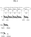
- FIGS. 3 and 4 are diagrams for describing a shape modeling method according to an embodiment of the present invention.
- the shape modeling method may digitize the characteristic of the haptic object sample 10 recognized by a finger of the user and the amount of impact applied to the finger of the user.
- the shape modeling method may calculate shape modeling data SMdata corresponding to the texture object 11 by modeling a shape of the texture object 11, based on the Z-axis data Mz of the measurement data Mxyz supplied from the 3-axis sensor 173.
- the texture object 11 of the haptic object sample 10 may be defined as first to Nth shape units SU.1 to SU.N which are grouped by a certain unit.
- the 3-axis sensors 173 may measure a position change of the texture object 11 at first to Kth sensing times (SU(1).1 to SU(K).1) to (SU(1).N to SU(K).N), which are predetermined for the first to Nth shape units SU.1 to SU.N, to generate first to Kth measurement data Mxyz for each of the shape units and may supply the first to Kth measurement data Mxyz to the haptic signal modeling unit 190.
- the haptic signal modeling unit 190 may calculate, as shape modeling data SMdata(1) to SMdata(K) at a corresponding sensing time, an average value of pieces of Z-axis data Mz at the same sensing time for each of the shape units SU.1 to SU.N by using the Z-axis data Mz at the first to Kth sensing times (SU(1).1 to SU(K).1) to (SU(1).N to SU(K).N) for each of the first to Nth shape units SU.1 to SU.N, and may calculate the shape modeling data SMdata including the calculated shape modeling data SMdata(1) to SMdata(K) respectively corresponding to a plurality of sensing times, thereby digitizing (normalizing) a shape of the texture object 11 of the haptic object sample 10.
- the haptic signal modeling unit 190 may calculate deviations " ⁇ Mdata(1) to ⁇ Mdata(K)" between the shape modeling data SMdata(1) to SMdata(K) respectively corresponding to the sensing times and shape modeling data 0 to SMdata(k-1) corresponding to a previous sensing time, based on the Z-axis data Mz of the first to Kth measurement data Mxyz for each of the shape units SU.1 to SU.N and may calculate shape modeling deviation data ⁇ SMdata including the calculated deviations " ⁇ SMdata(1) to ⁇ SMdata(K)” between the shape modeling data SMdata(1) to SMdata(K) respectively corresponding to the sensing times.
- the shape modeling deviation data ⁇ SMdata may be applied for transferring strong tactility to the finger of the user according to a shape change of the texture object 11 when a finger sweep (or drag) of the user is performed for the texture object 11 of the haptic object sample 10:
- the shape modeling method may calculate impulse modeling data IMdata corresponding to the shape of the texture object 11 by modeling the amount of impact based on the X-axis data Mx of the measurement data Mxyz supplied from the 3-axis sensor 173.
- the texture object 11 provided in the haptic object sample 10 may be defined as first to Nth impulse units IU. 1 to IU.N which are grouped by a certain unit.
- the haptic signal modeling unit 190 may calculate, as impulse modeling data IMdata(1) to IMdata(K) at a corresponding sensing time, an average value of pieces of X-axis data Mx at the same sensing time for each of the impulse units IU.
- the haptic signal modeling unit 190 may calculate absolute deviations " ⁇ IMdata(1) to ⁇ IMdata(K)" between the impulse modeling data IMdata(1) to IMdata(K) respectively corresponding to the sensing times and impulse modeling data 0 to IMdata(k-1) corresponding to a previous sensing time, based on the X-axis data Mx of the first to Kth measurement data Mxyz for each of the shape units IU.1 to IU.N and may calculate impulse modeling deviation data ⁇ IMdata including the calculated absolute deviations " ⁇ IMdata(1) to ⁇ IMdata(K)” between the impulse modeling data IMdata(1) to IMdata(K) respectively corresponding to the sensing times.
- the impulse modeling deviation data ⁇ IMdata may be applied for transferring strong tactility to the finger of the user according to a shape change of the texture object 11 when the finger sweep (or drag) of the user is performed for the texture object 11 of the haptic object sample 10:
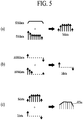
- FIG. 5 is a diagram for describing a shape rendering method.
- the shape rendering method may generate a haptic basic waveform HSa corresponding to the amount of impact and shape of the texture object 11 recognized by a finger of the user, based on data calculated through the above-described shape modeling.
- the shape rendering method may calculate shape data Sdata corresponding to a shape of the texture object 11, based on the shape modeling data SMdata and the impulse modeling data IMdata calculated through the above-described shape modeling, the shape rendering method may calculate impulse data Idata, based on the shape modeling deviation data ⁇ SMdata and the impulse modeling deviation data ⁇ IMdata, the method may generate the haptic basic waveform HSa, based on the calculated shape data Sdata and impulse data Idata, and may generate haptic basic waveform information corresponding to the haptic basic waveform HSa.
- the haptic signal modeling unit 190 may calculate the shape data Sdata by multiplying the shape modeling data SMdata and the impulse modeling data IMdata corresponding to the same sensing time.
- the haptic signal modeling unit 190 may calculate the impulse data Idata by multiplying the shape modeling deviation data ⁇ SMdata and the impulse modeling deviation data ⁇ IMdata corresponding to the same sensing time.
- the haptic signal modeling unit 190 may generate the haptic basic waveform HSa by summating the shape data Sdata and the impulse data Idata corresponding to the same sensing time.
- FIG. 6 is a diagram for describing a texture modeling method according to an embodiment of the present invention.
- the texture modeling method may model a vertical drag and a friction force, which are generated on a finger of the user, based on a material of the haptic object sample 10 to calculate friction force modeling data, vertical drag modeling data, and friction coefficient of the haptic object sample 10.
- the texture modeling method may calculate the vertical drag modeling data corresponding to the material of the haptic object sample 10, based on the Z-axis data Fz of the force measurement data Fxyz supplied from the force sensor 177 and may calculate the friction force modeling data corresponding to the material of the haptic object sample 10, based on the X-axis data Fx of the force measurement data Fxyz.
- the force sensor 177 may measure forces, which are applied to the haptic object sample 10 at the first to Kth sensing times SU(1) to SU(K) which are predetermined for the first to Nth shape units SU.1 to SU.N, to generate first to Kth force measurement data Fxyz for each of the shape units SU.1 to SU.N and may supply the first to Kth force measurement data Fxyz to the haptic signal modeling unit 190.
- the haptic signal modeling unit 190 may calculate vertical drag modeling data "F Normal ", based on the Z-axis data Fz of the first to Kth force measurement data Fxyz for each of the shape units SU.1 to SU.N. For example, the haptic signal modeling unit 190 may calculate the vertical drag modeling data "F Normal " as expressed in the following Equation (5).
- the haptic signal modeling unit 190 may calculate friction force modeling data "F Friction ", based on the X-axis data Fx of the first to Kth force measurement data Fxyz for each of the shape units SU.1 to SU.N. For example, the haptic signal modeling unit 190 may calculate the friction force modeling data "F Friction " as expressed in the following Equation (6).
- the haptic signal modeling unit 190 may summate the X-axis data Fx of the first to Kth force measurement data Fxyz in units of the shape units SU.1 to SU.N to calculate an absolute value of the average value "SU.(n)” and then may subtract the absolute average value "SU.(n)" of each of the shape units SU.1 to SU.N from the total number "N" of shape units to calculate the friction force modeling data "F Friction ".
- the first to Kth force measurement data Fxyz may have a positive (+) value or a negative (-) value according to a force direction
- the haptic signal modeling unit 190 may apply an offset value "Offset" in order for the first to Kth force measurement data Fxyz to have a positive (+) value or a negative (-) value with respect to zero.
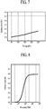
- FIG. 7 is a graph showing a correlation between a voltage level and a friction force in a texture rendering method.
- the texture rendering method may collect friction forces of the haptic object sample 10 based on voltage levels through pre-experiment and may generate a third lookup table where a correlation between the collected friction forces based on the voltage levels is mapped, based on the haptic basic waveform generated through the above-described shape rendering.
- the haptic signal modeling unit 190 may extract a voltage level based on friction force modeling data "F Friction " of the haptic object sample 10 calculated through the above-described texture modeling by using the third lookup table and may set the extracted voltage level as a haptic voltage level.
- the third lookup table may be stored in the memory 195.
- an electronic device that includes a touch panel for sensing a touch force as well as a touch position of a user touch may sense a touch force when there is a user touch, may calculate a vertical drag from the sensed touch force, may calculate a friction force by performing an arithmetic operation on the calculated vertical drag and the friction coefficient, and may extract a voltage level based on the friction force by using the third lookup table stored in the memory 195, and may set the extracted voltage level as the haptic voltage level.
- FIG. 8 is a graph showing a correlation between a frequency of a carrier waveform and a friction force in a texture rendering method.
- the texture rendering method may collect friction forces of the haptic object sample 10 based on frequencies of carrier waveforms through pre-experiment and may generate a fourth lookup table where a correlation between the collected friction forces of the haptic object sample 10 based on the frequencies of the carrier waveforms is mapped.
- the haptic signal modeling unit 190 may calculate a frequency based on the friction force modeling data "F Friction " of the haptic object sample 10 calculated through the above-described texture modeling by using the fourth lookup table and may set the extracted frequency as frequency information of a carrier waveform combined with a haptic basic waveform.
- the fourth lookup table may be stored in the memory 195.
- the electronic device that includes the touch panel for sensing a touch force as well as a touch position of a user touch may sense a touch force when there is a user touch, may calculate a vertical drag from the sensed touch force, may calculate a friction force by performing an arithmetic operation on the calculated vertical drag and the friction coefficient, and may extract a frequency based on the friction force by using the fourth lookup table stored in the memory 195, and may set the extracted frequency as the frequency information of the carrier waveform combined with the haptic basic waveform.
- FIG. 9 is a flowchart for describing a method of modeling a haptic signal from a haptic object, according to an embodiment of the present invention.
- a method of modeling a haptic signal from a haptic object according to an embodiment of the present invention will be described below with reference to FIGS. 2 to 9 .
- FIGS. 2 to 9 A method of modeling a haptic signal from a haptic object according to an embodiment of the present invention.
- the haptic object sample 10 including the texture object 11 may be located on the stage 10, and then, the sensor transport plate 130 may be transported according to driving of the plate transport unit 150.
- measurement data Mxyz of the texture object 11 measured by the 3-axis sensor 173 and force measurement data Fxyz measured by the force sensor 177 may be collected according to transporting of the sensor transport plate 130.
- shape modeling data SMdata corresponding to the texture object 11 of the haptic object sample 10 may be calculated by executing Equation (1) based on Z-axis data of the measurement data Mxyz, and impulse modeling data IMdata corresponding to the texture object 11 of the haptic object sample 10 may be calculated by executing Equation (3) based on X-axis data of the measurement data Mxyz.
- friction force modeling data "F Friction " corresponding to the haptic object sample 10 may be calculated based on X-axis data Fx of the force measurement data Fxyz.
- the friction force modeling data "F Friction” may be calculated by executing Equation (6) based on the force measurement data Fxyz, and its repetitive description is not repeated.
- setting information of the haptic signal based on the shape modeling data SMdata, the impulse modeling data IMdata, and the friction force modeling data "F Friction " may be generated.
- the setting information of the haptic signal may include haptic basic waveform information of the texture object 11 of the haptic object sample 10, the haptic voltage level, and frequency information of a carrier waveform combined with the haptic basic waveform.
- a first lookup table may be generated by mapping the setting information of the haptic signal to the haptic object sample 10 and may be stored in the memory 195.
- the memory 195 storing the first lookup table may be equipped in an electronic device that includes a touch panel for sensing only a touch position of a user touch.
- operation S140-1 haptic basic waveform information based on the shape modeling data SMdata and the impulse modeling data IMdata may be generated.
- operation S140-1 may include: an operation of calculating shape modeling deviation data ⁇ SMdata by executing Equation (2) based on the shape modeling data SMdata and calculating impulse modeling deviation data ⁇ IMdata by executing Equation (4) based on the impulse modeling data IMdata; an operation of calculating shape data Sdata by multiplying the shape modeling data SMdata and the impulse modeling data IMdata corresponding to the same sensing time; an operation of calculating impulse data Idata by multiplying the shape modeling deviation data ⁇ SMdata and the impulse modeling deviation data ⁇ IMdata corresponding to the same sensing time; an operation of generating a haptic basic waveform HSa by summating the shape data Sdata and the impulse data Idata corresponding to the same sensing time; and an operation of generating the haptic basic waveform information corresponding to the haptic basic waveform HSa.
- a voltage level based on friction force modeling data "F Friction " of the haptic object sample 10 may be extracted from a third lookup table where a correlation between friction forces of the haptic object sample based on voltage levels is mapped, and the extracted voltage level may be set as a haptic voltage level of the haptic basic waveform HSa.
- a frequency based on the friction force modeling data "F Friction" may be extracted from a fourth lookup table where a correlation between friction forces of the haptic object sample based on frequency information of carrier waveforms is mapped, and the extracted frequency may be set as the frequency information of the carrier waveforms.
- the method of modeling a haptic signal from a haptic object may model setting information of a haptic signal for providing a user with a texture as well as a shape of a haptic object sample.
- FIG. 10 is a flowchart for describing a method of modeling a haptic signal from a haptic object, according to another embodiment of the present invention.
- a method of modeling a haptic signal from a haptic object according to another embodiment of the present invention will be described below with reference to FIGS. 2 to 9 and 10 .
- FIGS. 2 to 9 and 10 A method of modeling a haptic signal from a haptic object according to another embodiment of the present invention.
- the haptic object sample 10 including the texture object 11 may be located on the stage 10, and then, the sensor transport plate 130 may be transported according to driving of the plate transport unit 150.
- measurement data Mxyz of the texture object 11 measured by the 3-axis sensor 173 and force measurement data Fxyz measured by the force sensor 177 may be collected according to transporting of the sensor transport plate 130.
- shape modeling data SMdata corresponding to the texture object 11 of the haptic object sample 10 may be calculated by executing Equation (1) based on Z-axis data of the measurement data Mxyz, and impulse modeling data IMdata corresponding to the texture object 11 of the haptic object sample 10 may be calculated by executing Equation (3) based on X-axis data of the measurement data Mxyz.
- friction force modeling data "F Friction " corresponding to the haptic object sample 10 may be calculated based on X-axis data Fx of the force measurement data Fxyz.
- the friction force modeling data "F Friction” may be calculated by executing Equation (6) based on the force measurement data Fxyz, and its repetitive description is not repeated.
- setting information of the haptic signal based on the shape modeling data SMdata, the impulse modeling data IMdata, the force measurement data Fxyz, and the friction force modeling data "F Friction " may be generated.
- the setting information of the haptic signal may include haptic basic waveform information of the texture object 11 of the haptic object sample 10 and a friction coefficient " ⁇ " of the haptic object sample 10.
- a second lookup table may be generated by mapping the setting information of the haptic signal to the haptic object sample 10 and may be stored in the memory 195, and a third lookup table where a correlation between friction forces of the haptic object sample 10 based on voltage levels and a fourth lookup table where a correlation between friction forces of the haptic object sample 10 based on frequencies of carrier waveforms may be additionally stored in the memory 195.
- the memory 195 storing the second to fourth lookup tables may be equipped in an electronic device that includes a touch panel for sensing a touch force as well as a touch position of a user touch.
- operation S240-1 haptic basic waveform information based on the shape modeling data SMdata and the impulse modeling data IMdata may be generated.
- operation S240-1 may include: an operation of calculating shape modeling deviation data ⁇ SMdata by executing Equation (2) based on the shape modeling data SMdata and calculating impulse modeling deviation data ⁇ IMdata by executing Equation (4) based on the impulse modeling data IMdata; an operation of calculating shape data Sdata by multiplying the shape modeling data SMdata and the impulse modeling data IMdata corresponding to the same sensing time; an operation of calculating impulse data Idata by multiplying the shape modeling deviation data ⁇ SMdata and the impulse modeling deviation data ⁇ IMdata corresponding to the same sensing time; an operation of generating a haptic basic waveform HSa by summating the shape data Sdata and the impulse data Idata corresponding to the same sensing time; and an operation of generating the haptic basic waveform information corresponding to the haptic basic waveform HSa.
- operation S240-2 the friction coefficient " ⁇ " of the haptic object sample 10 may be calculated based on the force measurement data Fxyz and the friction force modeling data "F Friction ".
- operation S240-2 may include: an operation of calculating vertical drag modeling data "F Normal " by executing Equation (5) based on Z-axis data of the force measurement data Fxyz; and an operation of calculating the friction coefficient " ⁇ ” by executing Equation (7) based on the vertical drag modeling data "F Normal " and the friction force modeling data "F Friction ".
- the method of modeling a haptic signal from a haptic object may model setting information of a haptic signal for simultaneously realizing a texture and a shape of a haptic object sample.
- the apparatus and method for modeling a haptic signal from a haptic object may generate, through a modeling method and a rendering method, a lookup table where setting information of a haptic signal, which includes haptic basic waveform information of each of a plurality of haptic object samples, a haptic voltage level of a haptic basic waveform, and frequency information of a carrier waveform, is mapped for each of various haptic object samples 10 and may store the first lookup table in a memory, thereby building a database of the setting information of the haptic signal for simultaneously realizing a shape and a texture of a haptic object for each haptic object sample.
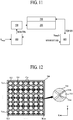
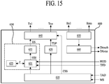
- FIG. 11 is a block diagram schematically illustrating a display apparatus according to a first embodiment of the present invention.
- FIG. 12 is a diagram schematically illustrating an electrode structure of a touch panel illustrated in FIG. 11 .
- FIG. 13 is a block diagram for describing a touch driver illustrated in FIG. 11 .
- the display apparatus may include a display panel 200, a touch panel 300, a controller 400, a display driver 500, and a touch driver 600.
- the display panel 200 may include a plurality of pixels which are respectively provided in a plurality of pixel areas defined by a plurality of gate lines and a plurality of data lines. Each of the plurality of pixels may display a certain image in response to a signal supplied from the display driver 500.
- the display panel 200 including the plurality of pixels may be a liquid crystal display panel or an organic light emitting display panel known to those skilled in the art, and thus, its detailed description is not provided.
- the touch panel 300 may include a plurality of transmission lines Tx1 to Txn and a plurality of reception lines Rx1 to Rxm.
- the plurality of transmission lines Tx1 to Txn may be arranged in parallel at predetermined intervals along a first direction Y in the touch panel 300.
- Each of the plurality of transmission lines Tx1 to Txn may include a plurality of touch driving electrodes 312, which are arranged at predetermined intervals along a second direction X intersecting the first direction Y, and a plurality of first bridges 312a that each connect adjacent touch driving electrodes 312 among the plurality of touch driving electrodes 312.
- each of the touch driving electrodes 312 may have a plane having a polygonal shape, for example, a diamond shape.
- Each of the plurality of first bridges 312a may connect adjacent touch driving electrodes 312.
- Each of the plurality of transmission lines Tx1 to Txn may be separately connected to the touch driver 600 and may be used as a haptic electrode that generates an attractive force according to a haptic signal to provide tactility to a finger of a user.
- the plurality of reception lines Rx1 to Rxm may be arranged in parallel at predetermined intervals along the second direction X in the touch panel 300.
- Each of the plurality of reception lines Rx1 to Rxm may include a plurality of touch sensing electrodes 314, which are arranged at predetermined intervals along the first direction Y, and a plurality of second bridges 314a that each connect adjacent touch sensing electrodes 314 among the plurality of touch sensing electrodes 314.
- Each of the touch sensing electrodes 314 may have a plane which is the same as that of the touch driving electrodes 312, and may be disposed between the touch driving electrodes 312. Therefore, the plurality of touch driving electrodes 312 and the plurality of touch sensing electrodes 314 may be disposed in a check shape.
- Each of the second bridges 314a may be provided to intersect a corresponding first bridge 312a to electrically connect adjacent touch sensing electrodes 314.
- Each of the plurality of reception lines Rx1 to Rxm may be separately connected to the touch driver 600 and may be used as a haptic electrode that generates an attractive force according to the haptic signal to provide tactility to a finger of a user.
- the plurality of transmission lines Tx1 to Txn and the plurality of reception lines Rx1 to Rxm may be provided to intersect each other with an insulating layer (or a dielectric layer) therebetween. Therefore, the insulating layer may generate a mutual capacitance Cm between the touch driving electrode 312 and the touch sensing electrode 314 adjacent thereto.
- the mutual capacitance Cm may act as a touch sensor that senses a user touch applied to the touch panel 300.
- each of the plurality of transmission lines Tx1 to Txn includes the diamond-shaped electrode 321 and each of the plurality of reception lines Rx1 to Rxm includes the diamond-shaped electrode 314, but the present disclosure is not limited thereto.
- the plurality of transmission lines Tx1 to Txn may be provided in a bar shape without including the electrodes 312, and the plurality of reception lines Rx1 to Rxm may be provided in a bar shape without including the electrodes 314.
- the touch panel 300 may have a structure of a mutual capacitive touch panel known to those skilled in the art.
- the touch panel 300 may be disposed on or directly attached to a top of the display panel 200.
- the display panel 200 is a liquid crystal display panel (or an organic light emitting display panel) including an upper polarizing film (not shown)
- the touch panel 300 may be disposed on the upper polarizing film or may be disposed between an upper substrate (not shown) and the upper polarizing film.
- the controller 400 may generate frame-unit image data RGB and a timing synchronization signal TSS, based on image source data "S Image " input from the outside and may supply the image data RGB and the timing synchronization signal TSS to the display driver 500.
- the controller 400 may calculate touch area data TAD corresponding to a user touch area, based on touch sensing data Dtouch supplied from the touch driver 600 and may execute an application program associated with the calculated touch area data TAD.
- the controller 400 may extract haptic object data HOD from the image source data "S Image ", based on the touch area data TAD and may supply the extracted haptic object data HOD to the touch driver 600.
- the image source data "S Image " of one frame may include image data, corresponding to a frame image displayed by the display panel 200, and the haptic object data HOD corresponding to a haptic object included in the frame image. Therefore, the controller 400 may extract haptic object data HOD of the user touch area, corresponding to the touch area data TAD, from the haptic object data HOD included in the frame-unit image source data "S Image " and may supply the extracted haptic object data HOD to the touch driver 600.
- the display driver 500 may supply data signals respectively corresponding to the image data RGB to the respective pixels by using the image data RGB and the timing synchronization signal TSS which are supplied from the controller 400, thereby displaying a certain image in the display panel 200.
- the display driver 500 may include: a timing controller (not shown) that generates a gate control signal and a data control signal by using the timing synchronization signal TSS supplied from the controller 400 and aligns the image data RGB to generate pixel data; a gate driving circuit unit that generates a gate signal according to the gate control signal and sequentially supplies the gate signal to the plurality of gate lines; and a data driving circuit unit (not shown) that converts pixel data into data signals according to the data control signal and respectively supplies the data signals to the plurality of data lines.
- the touch driver 600 may be driven in a touch mode or a haptic mode according to mode control by the controller 400.
- the touch driver 600 may sequentially supply a touch driving pulse TDP to the plurality of transmission lines Tx1 to Txn, may sense a capacitance change of a touch sensor Cm based on a user touch applied to the touch panel 300 through the plurality of reception lines Rx1 to Rxm to generate the touch sensing data Dtouch, and may supply the touch sensing data Dtouch to the controller 400.
- the touch driver 600 may generate a haptic basic waveform and a haptic signal HS combined with a carrier waveform, based on the touch area data TAD and the haptic object data HOD which are supplied from the controller 400, may select at least one transmission line included in the user touch area from among the plurality of transmission lines Tx1 to Txn, and may supply the haptic signal HS to the selected transmission line. Therefore, an attractive force may be generated in the user touch area according to the haptic signal HS supplied through a corresponding transmission line, and thus, a user may feel a tactile sense.
- the touch driver 600 may include a timing generating unit 610, a driving pulse supplying unit 620, a haptic driving unit 630, a channel selecting unit 640, a sensing unit 650, and a touch data processing unit 660.
- the touch driving unit 600 including the elements may be integrated into one readout integrated circuit (ROIC) chip.
- the touch data processing unit 660 may not be integrated into the ROIC chip but may be built into the controller 400.
- the timing generating unit 610 may generate a touch timing signal and a channel selection signal CSS for touch sensing driving of the touch driver 600 in response to a mode signal MS based on the touch mode supplied from the controller 400. Also, the timing generating unit 610 may generate a haptic timing signal for haptic driving of the touch driver 600 and generate the channel selection signal CSS corresponding to the touch area data TAD supplied from the controller 400, in response to the mode signal based on the haptic mode supplied from the controller 400
- the driving pulse supplying unit 620 may generate a touch driving pulse TDP in response to the touch timing signal supplied from the timing generating unit 610 and may sequentially supply the generated touch driving pulse TDP to the plurality of transmission lines Tx1 to Txn through the channel selecting unit 640.
- the touch driving pulse TDP may include a plurality of pulses so as to increase a charging amount of the touch sensor Cm and thus enhance sensing sensitivity.
- the haptic driving unit 630 may generate the haptic basic waveform and the haptic signal HS combined with a carrier waveform, based on the haptic object data HOD supplied from the controller 400 and may supply the haptic signal HS to at least one transmission line, included in a touch area corresponding to the touch area data TAD supplied from the controller 400, among the plurality of transmission lines Tx1 to Txn.
- the haptic driving unit 630 may include a haptic signal setting unit 631, a haptic signal generating unit 633, and a memory 635.
- the memory 635 may store setting information of a haptic signal which includes haptic basic waveform information corresponding to a haptic basic waveform of each of various haptic object samples, a haptic voltage level of a haptic basic waveform, and frequency information of a carrier waveform combined with the haptic basic waveform, which are set by the apparatus and method for modeling a haptic signal from a haptic object according to an embodiment of the present invention.
- the memory 635 may be provided inside the haptic driving unit 630 or may be provided inside or outside the touch driver 600.
- the haptic signal setting unit 631 may extract setting information HSI of a haptic signal, corresponding to the haptic object data HOD supplied from the controller 400, from the setting information of the haptic signal stored in the memory 635 and may supply the extracted setting information HSI of the haptic signal to the haptic signal generating unit 633. That is, the haptic signal setting unit 631 may extract the setting information HSI of the haptic signal (i.e., haptic basic waveform information, a haptic voltage level, and frequency information of a carrier waveform), corresponding to the haptic object data HOD, from a first lookup table stored in the memory 635.
- the setting information HSI of the haptic signal i.e., haptic basic waveform information, a haptic voltage level, and frequency information of a carrier waveform
- the haptic signal generating unit 633 may generate the haptic signal HS, based on the setting information HSI of the haptic signal (i.e., the haptic basic waveform information, the haptic voltage level, and the frequency information of the carrier waveform) supplied from the haptic signal setting unit 631.
- the haptic signal generating unit 633 may generate a haptic basic waveform HBW shown in FIG. 14 (a) , based on the haptic basic waveform information and the haptic voltage level, may generate a carrier waveform CW shown in FIG. 14 (b) , based on the frequency information of the carrier waveform, and may combine the haptic basic waveform HBW with the carrier waveform CW to generate the haptic signal HS shown in FIG. 14 (c) or (d) .
- the haptic signal generating unit 633 may select, as a reference waveform, at least one waveform corresponding to the haptic basic waveform information from among a sine waveform, a triangular waveform, a square waveform, a pulse waveform, and a sawtooth waveform and may modulate the selected reference waveform to generate the haptic basic waveform HBW corresponding to the haptic basic waveform information.
- the haptic signal generating unit 633 may combine the haptic basic waveform with the carrier waveform CW through frequency modulation based on a frequency addition combination method to generate the haptic signal HS shown in FIG. 14 (c) .
- the haptic signal generating unit 633 may modulate the amplitude of the carrier waveform according to the haptic basic waveform by using an amplitude modulation method to generate the haptic signal HS having a double side band as shown in FIG. 14 (d) .
- the haptic signal generating unit 633 may add a high-frequency carrier waveform CW, which is incapable of being recognized by the user, into a low-frequency haptic basic waveform HBW to generate the haptic signal HS, thereby enabling the user to feel a tactile sense having a shape and a texture of a haptic object when the user touches the touch panel.
- the channel selecting unit 640 may be separately connected to each of the plurality of transmission lines Tx1 to Txn and may be connected to the driving pulse supplying unit 620 and the haptic driving unit 630, thereby connecting a transmission line Tx, corresponding to the channel selection signal CSS, to the driving pulse supplying unit 620 or the haptic driving unit 630.
- the channel selecting unit 640 may transfer the touch driving pulse TDP, supplied from the driving pulse supplying unit 620, to a transmission line Tx corresponding to the channel selection signal CSS based on the touch mode.
- the channel selecting unit 640 may transfer the haptic signal HS, supplied from the haptic driving unit 630, to a transmission line Tx corresponding to the channel selection signal CSS based on the haptic mode.
- the channel selecting unit 640 may include a plurality of multiplexers.
- the sensing unit 650 may be connected to each of the plurality of reception lines Rx1 to Rxm. In response to a sampling signal from the timing generating unit 610, the sensing unit 650 may sense a change amount of a capacitance of a corresponding touch sensor Cm through each of the plurality of reception lines Rx1 to Rxm and may analog-digital convert the generated sensing signal to generate the touch sensing data Dtouch.
- the touch data processing unit 660 may receive the touch sensing data Dtouch input from the sensing unit 650 and may sequentially store the touch sensing data Dtouch in an internal memory. In response to a touch report signal from the timing generating unit 610, the touch data processing unit 660 may transfer the touch sensing data Dtouch, stored in the internal memory, to the controller 400.
- the controller 400 may receive the touch sensing data Dtouch transferred from the touch data processing unit 660 and may compare the received touch sensing data Dtouch with a predetermined threshold value to determine whether there is a touch and calculate touch coordinates by using sensing data greater than the threshold value. Also, the controller 400 may calculate the touch coordinates (XY coordinates), based on position information (Y coordinates) of the touch sensing electrode 314 from which the touch sensing data Dtouch is generated and position information (X coordinates) of the touch driving electrode 312 which is being driven and may execute an application program associated with the touch coordinates. Also, the controller 400 may generate the touch area data TAD corresponding to the calculated touch coordinates and may supply the touch area data TAD to the touch driver 600.
- the display apparatus may generate a haptic signal having a shape and a texture of a haptic object corresponding to a user touch area to generate an attractive force in the user touch area, based on setting information of a haptic signal which is previously set by the method of modeling a haptic signal from a haptic object and is stored in a memory, thereby providing a finger of a user with a tactile sense having the same shape and texture as those of the haptic object.
- An alternative display apparatus may include a capacitive touch panel disclosed in U.S. Patent Publication No. 2014-0062933 or a touch panel disclosed in Korean Patent Application No. 2014-0076794 , instead of the above-described touch panel 300.
- the display apparatus may sense a touch force as well as a touch position when a user touches the touch panel.
- the alternative display apparatus may calculate touch area data TAD corresponding to a user touch area, based on touch sensing data supplied from the touch driver 600 and may calculate touch force data, based on touch force sensing data supplied from the touch driver 600. Also, the controller 400 may extract haptic object data HOD from image source data "S image ", based on the touch area data TAD.
- a touch driver 600 may include a timing generating unit 610, a driving pulse supplying unit 620, a haptic driving unit 630, a channel selecting unit 640, a sensing unit 650, and a touch data processing unit 660.
- the elements other than the haptic driving unit 630 and the sensing unit 650 are as described above, and thus, their detailed descriptions are not repeated.
- the sensing unit 650 may sense a change amount of a capacitance of a corresponding touch sensor Cm through each of the plurality of reception lines Rx1 to Rxm and may analog-digital convert the generated sensing signal to generate touch sensing data Dtouch. Also, the sensing unit 650 may sense a user touch force applied to the touch panel 300 through a force sensing line to generate touch force sensing data Dforce and may supply the touch force sensing data Dforce to the controller 400.
- a touch force sensing operation performed by the sensing unit 650 is disclosed in U.S. Patent Publication No. 2014-0062933 or a touch panel disclosed in Korean Patent Application No. 2014-0076794 , and thus, its detailed description is not provided.
- the haptic driving unit 630 may generate a haptic signal HS, based on haptic object data HOD and touch force data TFD supplied from the controller 400 and may supply the generated haptic signal HS to a transmission line included in the user touch area.
- the haptic driving unit 630 may include a haptic signal setting unit 631, a haptic signal generating unit 633, and a memory 635.
- the above-described second to fourth lookup tables may be stored in the memory 635. That is, the memory 635 may store the second lookup table where haptic basic waveform information and a friction coefficient for each of various haptic object samples set by the apparatus and method for modeling a haptic signal from a haptic object according to an embodiment of the present invention are mapped, the third lookup table where a correlation between friction forces of the haptic object sample 10 based on voltage levels is mapped, and the fourth lookup table where a correlation between friction forces of the haptic object sample 10 based on frequencies of carrier waveforms is mapped.
- the haptic signal setting unit 631 may extract haptic basic waveform information and a friction coefficient " ⁇ ", corresponding to the haptic object data HOD, from the second lookup table stored in the memory 635. Subsequently, the haptic signal setting unit 631 may set the touch force data TFD, supplied from the controller 400, as a vertical drag value and may multiply the vertical drag value with the extracted friction coefficient " ⁇ " to calculate a friction force of a haptic object. Subsequently, the haptic signal setting unit 631 may extract a haptic voltage level and frequency information of a carrier waveform, corresponding to the friction force of the haptic object, from the third and fourth lookup tables stored in the memory 635.
- the haptic signal setting unit 631 may supply, to the haptic signal generating unit 633, setting information HIS of a haptic signal which includes the extracted haptic basic waveform information, haptic voltage level and frequency information of the carrier waveform.
- the haptic signal generating unit 633 may generate the haptic signal HS, based on the setting information HSI of the haptic signal (i.e., the haptic basic waveform information, the haptic voltage level, and the frequency information of the carrier waveform) supplied from the haptic signal setting unit 631.
- the setting information HSI of the haptic signal i.e., the haptic basic waveform information, the haptic voltage level, and the frequency information of the carrier waveform
- the alternative display apparatus provides the same effects as those of the first-described display apparatus.
- FIG. 16 is a diagram for describing another display apparatus.
- the display apparatus may include a display panel 200, a touch panel 300, a controller 400, a display driver 500, a touch driver 600, a haptic panel 700, and a haptic driver 800.
- the display panel 200, the touch panel 300, and the display driver 500 are as described above, and thus, their detailed descriptions are not repeated.
- the haptic panel 700 may be disposed on the touch panel 300 and may generate an attractive force in a user touch area to provide tactility to a finger of a user.
- the haptic panel 700 may include a transparent base substrate 710, a haptic electrode layer 720 provided on the transparent base substrate 710, and a protective film 730 covering the haptic electrode layer 720.
- the haptic electrode layer 720 may be provided all over a top of the transparent base substrate 710.
- the haptic electrode layer 720 may include a plurality of first haptic electrode patterns (not shown), which are arranged at certain intervals along a direction parallel to a transmission line of the touch panel 300, and a plurality of second haptic electrode patterns (not shown) which are arranged at certain intervals along a direction parallel to a reception line of the touch panel 300.
- the protective film 730 may act as an insulator that covers the haptic electrode layer 720.
- the controller 400 is as described above except that the controller 400 supplies the haptic driver 800 with a mode signal MS and haptic object data HOD based on the haptic mode, and thus, its detailed description is not repeated.
- the touch driver 600 may sequentially supply a touch driving pulse TDP to the plurality of transmission lines Tx1 to Txn and may sense, through the plurality of reception lines Rx1 to Rxm, a capacitance change of a touch sensor Cm based on a user touch applied to the touch panel 300 to supply touch sensing data Dtouch to the controller 400.
- the touch driver 600 may include a timing generating unit 610, a driving pulse supplying unit 620, a sensing unit 650, and a touch data processing unit 660 among the elements illustrated in FIG. 13 .
- the timing generating unit 610 may generate a touch timing signal for touch sensing driving of the touch driver 600 in response to the mode signal MS based on the touch mode supplied from the controller 400.
- the driving pulse supplying unit 620 may generate a touch driving pulse TDP and may sequentially supply the generated touch driving pulse TDP to the plurality of transmission lines Tx1 to Txn.
- the sensing unit 650 may sense a change amount of a capacitance of a corresponding touch sensor Cm through each of the plurality of reception lines Rx1 to Rxm and may analog-digital convert the generated sensing signal to generate the touch sensing data Dtouch.
- the touch data processing unit 660 may receive the touch sensing data Dtouch input from the sensing unit 650 and may sequentially store the touch sensing data Dtouch in an internal memory. In response to a touch report signal from the timing generating unit 610, the touch data processing unit 660 may transfer the touch sensing data Dtouch, stored in the internal memory, to the controller 400. Therefore, the controller 400 may receive the touch sensing data Dtouch transferred from the touch data processing unit 660, may calculate touch coordinates based on the received touch sensing data Dtouch, and may execute an application program associated with the touch coordinates.
- the haptic driver 800 may generate a haptic signal HS, based on the haptic object data HOD supplied from the controller 400 and may supply the haptic signal HS to the haptic electrode layer 720 of the haptic panel 700.
- the haptic driver 800 may include a haptic signal setting unit 631, a haptic signal generating unit 633, and a memory 635.
- the haptic driver 800 including the elements is as described above except that the haptic driver 800 supplies the haptic signal HS to the haptic electrode layer 720 of the haptic panel 700, and thus, its detailed description is not repeated.
- the aforementioned display apparatus provides the same effects as those of the first-described display apparatus.
- Another display apparatus may include elements other than the touch panel among the elements included in the aforementioned display apparatus and may include the capacitive touch panel disclosed in U.S. Patent Publication No. 2014-0062933 or a touch panel disclosed in Korean Patent Application No. 2014-0076794 , instead of the touch panel.
- the display apparatus may generate a haptic signal in the same method as the aforementioned display apparatus and may supply the generated haptic signal to the haptic electrode layer 720 of the haptic panel, thereby providing the same effects as those of the first-described display apparatus.
- FIG. 17 is a diagram for describing a haptic signal.
- FIG. 17 (a) shows a haptic signal corresponding to a haptic object causing a low friction force like plastic
- FIG. 17 (b) shows a haptic signal corresponding to a haptic object causing a high friction force like rubbers.
- a haptic signal may be generated by combining a haptic basic waveform based on a shape of a haptic object with a carrier waveform based on a friction force caused by a material of the haptic object. Therefore, even when a haptic object includes the same texture objects 11, the haptic signal may have different shapes according to materials of the texture objects 11. Therefore, a haptic signal shown in FIG. 17 (a) may provide a user with tactility corresponding to a shape of a texture object 11 provided in a haptic object 10. On the other hand, a haptic signal shown in FIG.
- the present invention may simultaneously provide the user with tactility, corresponding to a shape of a texture object 11 provided in a haptic object 20, and tactility corresponding to a texture (or a friction force) of the texture object 11.
- the present invention may combine a high-frequency carrier waveform, which is incapable of being recognized by the user, into a low-frequency haptic basic waveform to generate a haptic signal, thereby enabling the user to feel a tactile sense having a shape and a texture of a haptic object.
- FIG. 18 is a flowchart for describing a method of driving a display apparatus and is for describing a haptic driving method performed by the display apparatus.
- touch sensing data Dtouch may be generated by sensing a user touch applied to the touch panel 300.
- touch area data TAD corresponding to a user touch area may be calculated based on the touch sensing data Dtouch.
- haptic object data HOD may be extracted from image source data "S Image ", based on the touch area data TAD.
- haptic object data HOD of the user touch area corresponding to the touch area data TAD may be extracted from the haptic object data HOD included in frame-unit image source data "S Image ".
- setting information of a haptic signal corresponding to the haptic object data HOD may be extracted from setting information of a haptic signal stored in the memory 635.
- operation S340 may include operation S340-1 of extracting haptic basic waveform information corresponding to the haptic object data HOD from the first lookup table stored in the memory 635, operation S340-2 of extracting a haptic voltage level from the first lookup table, and operation S340-3 of extracting frequency information of a carrier waveform from the first lookup table.
- a haptic signal HS may be generated based on the setting information HSI of the haptic signal (i.e., haptic basic waveform information, a haptic voltage level, and frequency information of a carrier waveform).
- operation S350 may include: an operation of generating the haptic basic waveform HBW shown in FIG. 14 (a) , based on the haptic basic waveform information and the haptic voltage level; an operation of generating the carrier waveform CW shown in FIG. 14 (b) , based on the frequency information and the carrier waveform; and an operation of combining the haptic basic waveform HBW with the carrier waveform CW to generate the haptic signal shown in FIG. 14 (c) or (d) .
- the haptic signal HS may be supplied to the transmission line of the touch panel 300 included in the user touch area to generate an attractive force in the user touch area, thereby providing the user with a tactile sense having a shape and a texture of the haptic object.
- the haptic signal HS may be supplied to the haptic electrode layer 720 of the haptic panel 700 provided on the touch panel 300.
- the method of driving the display apparatus may generate the haptic signal HS having a shape and a texture of the haptic object data HOD set in the user touch area to generate an attractive force in the user touch area, based on the setting information HIS of the haptic signal which is previously set by the method of modeling a haptic signal from a haptic object and is stored in a memory, thereby providing a finger of the user with a tactile sense having the same shape and texture as those of the haptic object data HOD.
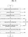
- FIG. 19 is a flowchart for describing a method of driving another display apparatus and is for describing a haptic driving method performed by the display apparatus.
- touch sensing data Dtouch may be generated by sensing a user touch applied to the touch panel 300, and touch force sensing data Dforce may be generated by sensing a user touch force based on the user touch.
- touch area data TAD corresponding to a user touch area may be calculated based on the touch sensing data Dtouch.
- haptic object data HOD may be extracted from image source data "S Image ", based on the touch area data TAD.
- haptic object data HOD of the user touch area corresponding to the touch area data TAD may be extracted from the haptic object data HOD included in frame-unit image source data "S Image ".
- setting information of a haptic signal corresponding to the haptic object data HOD may be extracted from setting information of a haptic signal stored in the memory 635.
- operation S440 may include: operation S440-1 of extracting a friction coefficient " ⁇ " and haptic basic waveform information, corresponding to the haptic object data HOD, from the second lookup table stored in the memory 635; operation S440-2 of setting the touch force data TFD as a vertical drag value and multiplying the vertical drag value and the extracted friction coefficient " ⁇ " to calculate a friction force of a haptic object; and operation S440-3 of extracting a haptic voltage level, corresponding to the friction force of the haptic object, from the third lookup table stored in the memory 635 and extracting frequency information of a carrier waveform, corresponding to the friction force of the haptic object, from the fourth lookup table stored in the memory 635.
- a haptic signal HS may be generated based on the setting information HSI of the haptic signal (i.e., haptic basic waveform information, a haptic voltage level, and frequency information of a carrier waveform).
- operation S450 may include: an operation of generating the haptic basic waveform HBW shown in FIG. 14 (a) , based on the haptic basic waveform information and the haptic voltage level; an operation of generating the carrier waveform CW shown in FIG. 14 (b) , based on the frequency information and the carrier waveform; and an operation of combining the haptic basic waveform HBW with the carrier waveform CW to generate the haptic signal shown in FIG. 14 (c) or (d) .
- the haptic signal HS may be supplied to the transmission line of the touch panel 300 included in the user touch area to generate an attractive force in the user touch area, thereby providing the user with a tactile sense having a shape and a texture of the haptic object.
- the haptic signal HS may be supplied to the haptic electrode layer 720 of the haptic panel 700 provided on the touch panel 300.
- the method of driving another display apparatus provides the same effects as those of the method of driving the previously described display apparatus.
- the display apparatus may be applied to a display unit of each of portable information devices, such as smartphones, tablet PCs, etc., and various electronic devices such as notebook computers, monitors, TVs, etc., which include a touch panel and a haptic function.
- portable information devices such as smartphones, tablet PCs, etc.
- electronic devices such as notebook computers, monitors, TVs, etc., which include a touch panel and a haptic function.
- the method of modeling a haptic signal from a haptic object may model setting information of a haptic signal for simultaneously realizing a shape and a texture of a haptic object sample.
- the display apparatus and the driving method thereof may generate a haptic signal having a shape and a texture of a haptic object corresponding to a user touch area to cause an attractive force in the user touch area, thereby providing a user with a tactile sense having the same shape and texture as those of the haptic object.
Landscapes
- Engineering & Computer Science (AREA)
- General Engineering & Computer Science (AREA)
- Theoretical Computer Science (AREA)
- Physics & Mathematics (AREA)
- General Physics & Mathematics (AREA)
- Human Computer Interaction (AREA)
- Data Mining & Analysis (AREA)
- Databases & Information Systems (AREA)
- Mathematical Physics (AREA)
- Software Systems (AREA)
- User Interface Of Digital Computer (AREA)
Claims (12)
- Ein Verfahren zum Modellieren eines haptischen Signals (HS) von einem haptischen Objekt (10), wobei das Modellierverfahren aufweist:Erhalten, durch eine Sensoreinheit (170), von Messdaten, welche mit einer Form eines Texturobjekts (11) korrespondieren, während die Sensoreinheit in Bezug auf das haptische Objekt (10), welches das Texturobjekt aufweist, bewegt wird;Erhalten, durch einen Kraftsensor (177), von Kraft-Messdaten, welche mit einem auf das haptische Objekt angewandten Druckpegel korrespondieren;Berechnen von Form-Modellierdaten und Impuls-Modellierdaten, welche mit dem Texturobjekt (11) korrespondieren, basierend auf den Messdaten;Berechnen von Reibungskraft-Modellierdaten, welche mit dem Texturobjekt (11) korrespondieren, basierend auf den Kraft-Messdaten;Erzeugen von Einstellungsinformationen eines haptischen Signals (HS), welches mit dem haptischen Objekt (10) korrespondiert, basierend auf den Form-Modellierdaten, den Impuls-Modellierdaten und den Reibungskraft-Modellierdaten; undSpeichern der Einstellungsinformationen des haptischen Signals (HS) in einem Speicher (635) ;wobei das Erzeugen der Einstellungsinformationen des haptischen Signals (HS) aufweist:Erzeugen einer Haptische-Basis-Wellenform, welche mit einer Form des haptischen Objekts (10) korrespondiert, basierend auf den Form-Modellierdaten und den Impuls-Modellierdaten, und Erzeugen von Haptische-Basis-Wellenform-Informationen, welche mit der Haptische-Basis-Wellenform korrespondieren;Einstellen eines Haptischer-Spannungspegels basierend auf den Reibungskraft-Modellierdaten; undErzeugen von Frequenzinformationen einer mit der Haptische-Basis-Wellenform kombinierten Träger-Wellenform, basierend auf den Reibungskraft-Modellierdaten.
- Das Verfahren gemäß Anspruch 1, wobei das Speichern der Einstellungsinformationen des haptischen Signals (HS) aufweist:Erzeugen einer ersten Nachschlagetabelle durch Abbilden der Haptische-Basis-Wellenform-Informationen, des Haptischer-Spannungspegels und der Frequenzinformationen der Träger-Wellenform auf das haptische Objekt (10); undSpeichern der ersten Nachschlagetabelle in dem Speicher (635).
- Ein Verfahren zum Modellieren eines haptischen Signals (HS) von einem haptischen Objekt (10), wobei das Modellierverfahren aufweist:Erhalten, durch eine Sensoreinheit (170), von Messdaten, welche mit einer Form eines Texturobjekts (11) korrespondieren, während die Sensoreinheit in Bezug auf ein haptisches Objekt (10), welches das Texturobjekt aufweist, bewegt wird;Erhalten, durch einen Kraftsensor (177), von Kraft-Messdaten, welche mit einem auf das haptische Objekt angewandten Druckpegel korrespondieren;Berechnen von Form-Modellierdaten und Impuls-Modellierdaten, welche mit dem Texturobjekt (11) korrespondieren, basierend auf den Messdaten;Berechnen von Reibungskraft-Modellierdaten, welche mit dem Texturobjekt (11) korrespondieren, basierend auf den Kraft-Messdaten;Erzeugen von Einstellungsinformationen eines haptischen Signals (HS), welche mit dem haptischen Objekt (10) korrespondieren, basierend auf den Form-Modellierdaten, den Impuls-Modellierdaten und den Reibungskraft-Modellierdaten; undSpeichern der Einstellungsinformationen des haptischen Signals (HS) in einem Speicher (635) ;wobei das Erzeugen der Einstellungsinformationen des haptischen Signals (HS) aufweist:Erzeugen einer Haptische-Basis-Wellenform, welche mit einer Form des haptischen Objekts (10) korrespondiert, basierend auf den Form-Modellierdaten und den Impuls-Modellierdaten, und Erzeugen der Haptische-Basis-Wellenform-Informationen, welche mit der Haptische-Basis-Wellenform korrespondieren; undBerechnen eines Reibungskoeffizienten, der mit dem haptischen Objekt (10) korrespondiert, basierend auf den Kraft-Messdaten und den Reibungskraft-Modellierdaten.
- Das Verfahren gemäß Anspruch 3, wobei das Speichern der Einstellungsinformationen des haptischen Signals (HS) aufweist:Erzeugen einer zweiten Nachschlagetabelle durch Abbilden der Haptische-Basis-Wellenform-Informationen und des Reibungskoeffizienten auf das haptische Objekt (10); undSpeichern der zweiten Nachschlagetabelle in dem Speicher (635).
- Das Verfahren gemäß Anspruch 4, ferner aufweisend: ein zusätzliches Speichern, in dem Speicher (635), einer dritten Nachschlagetabelle, in der eine Reibungskraft des haptischen Objekts (10) basierend auf einem Spannungspegel abgebildet wird, und einer vierten Nachschlagetabelle, in der eine Reibungskraft des haptischen Objekts (10) basierend auf einer Frequenz einer Träger-Wellenform abgebildet wird.
- Ein Verfahren zum Antreiben einer Anzeigevorrichtung, wobei das Verfahren aufweist:Erfassen einer Nutzerberührung, welche auf ein Berührungspanel (300) ausgeübt wird, um Berührung-Erfassungsdaten (Dtouch) zu erzeugen;Berechnen eines Berührungsbereichs basierend auf den Berührung-Erfassungsdaten;Extrahieren von Haptisches-Objekt-Daten (HOD) eines haptischen Objekts, das mit dem Berührungsbereich korrespondiert, aus Teilen von Haptisches-Objekt-Daten, welche in Eingangsbild-Quellendaten (Simage) enthalten sind;Erzeugen eines haptischen Signals (HS), welches eine Träger-Wellenform und eine Haptische-Basis-Wellenform, die mit den Haptisches-Objekt-Daten des haptischen Objekts korrespondiert, aufweist; undBewirken einer taktilen Empfindung in dem Berührungsbereich unter Verwendung des haptischen Signals (HS),wobei das Erzeugen des haptischen Signals (HS) aufweist:
Extrahieren, aus dem Speicher (635), eines durch ein Verfahren gemäß irgendeinem der Ansprüche 1 bis 5 modellierten haptischen Signals (HS). - Das Verfahren gemäß Anspruch 6, wobei das Erzeugen des haptischen Signals (HS) aufweist:ein Extrahieren, aus einem Speicher (635), von Haptische-Basis-Wellenform-Informationen und einem Haptischer-Spannungspegel, welche mit den Haptisches-Objekt-Daten (HOD) des haptischen Objekts korrespondieren, und Frequenzinformationen der Trägerwellenform;Erzeugen der Haptische-Basis-Wellenform basierend auf den Haptische-Basis-Wellenform-Informationen und dem Haptischer-Spannungspegel;Erzeugen der Träger-Wellenform basierend auf den Frequenzinformationen der Träger-Wellenform; undKombinieren der Haptische-Basis-Wellenform mit der Träger-Wellenform, um das haptische Signal (HS) zu erzeugen.
- Das Verfahren gemäß Anspruch 6, ferner aufweisend ein Erfassen einer Nutzer-Berührungskraft, welche auf ein Berührungspanel angewandt wird, um Berührungskraft-Daten (TFD) zu berechnen,
wobei das Erzeugen des haptischen Signals (HS) aufweist:Extrahieren eines Reibungskoeffizienten, welcher mit den Haptisches-Objekt-Daten (HOD) des haptischen Objekts korrespondiert, aus einem Speicher (635), um eine Reibungskraft des haptischen Objekts zu berechnen, basierend auf den Berührungskraft-Daten (TFD) und dem Reibungskoeffizienten;Extrahieren, aus dem Speicher (635), von Haptische-Basis-Wellenform-Informationen, welche mit dem Haptisches-Objekt-Daten des haptischen Objekts korrespondieren, einem Haptischer-Spannungspegel, welcher mit der Reibungskraft des haptischen Objekts korrespondiert, und Frequenzinformationen der Träger-Wellenform;Erzeugen der Haptische-Basis-Wellenform basierend auf den extrahierten Haptische-Basis-Wellenform-Informationen und dem Haptischer-Spannungspegel;Erzeugen der Träger-Wellenform basierend auf den Frequenzinformationen der Träger-Wellenform; undKombinieren der Haptische-Basis-Wellenform mit der Träger-Wellenform, um das haptische Signal (HS) zu erzeugen. - Das Verfahren gemäß einem der Ansprüche 6 bis 8, wobei das haptische Signal (HS) an mindestens eine Übertragungsleitung bereitgestellt wird, welche in dem Berührungspanel (300) bereitgestellt ist.
- Das Verfahren gemäß einem der Ansprüche 6 bis 8, wobei das haptische Signal (HS) an eine haptische Elektrodenschicht (720) bereitgestellt wird, welche in einem haptischen Panel (700), das auf dem Berührungspanel (300) angeordnet ist, enthalten ist.
- Eine Vorrichtung zum Modellieren eines haptischen Signals (HS) von einem haptischen Objekt (10), wobei die Vorrichtung aufweist:eine Sensoreinheit (170), die konfiguriert ist zum Erhalten von Messdaten, die mit einer Form eines Texturobjekts (11) korrespondieren, während die Sensoreinheit in Bezug auf das haptische Objekt (10), welches das Texturobjekt aufweist, bewegt wird;einen Kraftsensor (177), der konfiguriert ist zum Erhalten von Kraft-Messdaten, welche mit einem Druckpegel, der auf das haptische Objekt angewandt wird, korrespondieren;eine Haptisches-Signal-Modelliereinheit (190), die konfiguriert ist zum:- Berechnen von Form-Modellierdaten und Impuls-Modellierdaten, die mit dem Texturobjekt (11) korrespondieren, basierend auf den Form-Messdaten;- Berechnen von Reibungskraft-Modellierdaten, welche mit dem Texturobjekt (11) korrespondieren, basierend auf den Kraft-Messdaten;- Erzeugen von Einstellungsinformationen eines haptischen Signals (HS), welche mit dem haptischen Objekt (10) korrespondieren, basierend auf den Form-Modellierdaten, den Impuls-Modellierdaten und den Reibungskraft-Modellierdaten; und- Speichern der Einstellungsinformationen des haptischen Signals (HS) in einem Speicher (635),wobei die Haptisches-Signal-Modelliereinheit (190) konfiguriert ist zum Erzeugen der Einstellungsinformationen des haptischen Signals (HS) durch:Erzeugen einer Haptische-Basis-Wellenform, welche mit einer Form des haptischen Objekts (10) korrespondiert, basierend auf den Form-Modellierdaten und den Impuls-Modellierdaten, und Erzeugen von Haptische-Basis-Wellenform-Informationen, welche mit der Haptische-Basis-Wellenform korrespondieren;Einstellen eines Haptischer-Spannungspegels basierend auf den Reibungskraft-Modellierdaten; undErzeugen von Frequenzinformationen einer mit der Haptische-Basis-Wellenform kombinierten Träger-Wellenform, basierend auf den Reibungskraft-Modellierdaten.
- Eine Vorrichtung zum Modellieren eines haptischen Signals (HS) von einem haptischen Objekt (10), wobei die Vorrichtung aufweist:eine Sensoreinheit (170), die konfiguriert ist zum Erhalten von Messdaten, die mit einer Form eines Testurobjekts (11) korrespondieren, während die Sensoreinheit in Bezug auf das haptische Objekt (10), welches das Texturobjekt aufweist, bewegt wird;einen Kraftsensor (177), der konfiguriert ist zum Erhalten von Kraft-Messdaten, welche mit einem Druckpegel, der auf das haptische Objekt angewandt wird, korrespondieren;eine Haptisches-Signal-Modelliereinheit (190), die konfiguriert ist zum:- Berechnen von Form-Modellierdaten und Impuls-Modellierdaten, die mit dem Texturobjekt (11) korrespondieren, basierend auf den Form-Messdaten;- Berechnen von Reibungskraft-Modellierdaten, welche mit dem Texturobjekt (11) korrespondieren, basierend auf den Kraft-Messdaten;- Erzeugen von Einstellungsinformationen eines haptischen Signals (HS), welche mit dem haptischen Objekt (10) korrespondieren, basierend auf den Form-Modellierdaten, den Impuls-Modellierdaten und den Reibungskraft-Modellierdaten; und- Speichern der Einstellungsinformationen des haptischen Signals (HS) in einem Speicher (635),wobei die Haptisches-Signal-Modelliereinheit (190) konfiguriert ist zum Erzeugen der Einstellungsinformationen des haptischen Signals (HS) durch:Erzeugen einer Haptische-Basis-Wellenform, welche mit einer Form des haptischen Objekts (10) korrespondiert, basierend auf den Form-Modellierdaten und den Impuls-Modellierdaten, und Erzeugen der Haptische-Basis-Wellenform-Informationen, welche mit der Haptische-Basis-Wellenform korrespondieren; undBerechnen eines Reibungskoeffizienten, welcher mit dem haptischen Objekt (10) korrespondiert, basierend auf den Kraft-Messdaten und den Reibungskraft-Modellierdaten.
Applications Claiming Priority (1)
| Application Number | Priority Date | Filing Date | Title |
|---|---|---|---|
| KR1020140157324A KR102398389B1 (ko) | 2014-11-12 | 2014-11-12 | 햅틱 객체로부터 햅틱 신호를 모델링하는 방법, 디스플레이 장치 및 이의 구동 방법 |
Publications (2)
| Publication Number | Publication Date |
|---|---|
| EP3021202A1 EP3021202A1 (de) | 2016-05-18 |
| EP3021202B1 true EP3021202B1 (de) | 2018-07-04 |
Family
ID=54540887
Family Applications (1)
| Application Number | Title | Priority Date | Filing Date |
|---|---|---|---|
| EP15193621.8A Active EP3021202B1 (de) | 2014-11-12 | 2015-11-09 | Verfahren zur modellierung von haptischem signal aus haptischem objekt, anzeigevorrichtung und ansteuerungsverfahren dafür |
Country Status (5)
| Country | Link |
|---|---|
| US (1) | US9984479B2 (de) |
| EP (1) | EP3021202B1 (de) |
| KR (1) | KR102398389B1 (de) |
| CN (1) | CN105589557B (de) |
| TW (1) | TWI632494B (de) |
Families Citing this family (7)
| Publication number | Priority date | Publication date | Assignee | Title |
|---|---|---|---|---|
| JP6073451B1 (ja) * | 2015-11-17 | 2017-02-01 | 京セラ株式会社 | 電子機器 |
| KR102462941B1 (ko) * | 2016-01-26 | 2022-11-03 | 삼성디스플레이 주식회사 | 표시 장치 |
| CN112146701B (zh) * | 2020-09-17 | 2022-09-30 | 五邑大学 | 一种触觉测量装置及方法 |
| WO2023037463A1 (ja) * | 2021-09-09 | 2023-03-16 | 豊田合成株式会社 | 触感提示装置 |
| US12111968B2 (en) * | 2021-11-25 | 2024-10-08 | Electronics And Telecommunications Research Institute | Haptic feedback system |
| CN114265503B (zh) * | 2021-12-22 | 2023-10-13 | 吉林大学 | 一种应用于笔式振动触觉反馈装置的纹理渲染方法 |
| KR102756642B1 (ko) | 2022-12-29 | 2025-01-16 | 경희대학교 산학협력단 | 햅틱 질감 예측 장치 및 방법 |
Family Cites Families (18)
| Publication number | Priority date | Publication date | Assignee | Title |
|---|---|---|---|---|
| FI20085475A0 (fi) | 2008-05-19 | 2008-05-19 | Senseg Oy | Kosketuslaiteliitäntä |
| JP2010086471A (ja) * | 2008-10-02 | 2010-04-15 | Sony Corp | 操作感提供装置、および操作感フィードバック方法、並びにプログラム |
| US9746923B2 (en) | 2009-03-12 | 2017-08-29 | Immersion Corporation | Systems and methods for providing features in a friction display wherein a haptic effect is configured to vary the coefficient of friction |
| EP2406704A1 (de) | 2009-03-12 | 2012-01-18 | Immersion Corporation | Systeme und verfahren für eine textur-engine |
| CN101907922B (zh) | 2009-06-04 | 2015-02-04 | 新励科技(深圳)有限公司 | 一种触感触控系统 |
| US20110267294A1 (en) * | 2010-04-29 | 2011-11-03 | Nokia Corporation | Apparatus and method for providing tactile feedback for user |
| US20120327006A1 (en) * | 2010-05-21 | 2012-12-27 | Disney Enterprises, Inc. | Using tactile feedback to provide spatial awareness |
| CN102054122B (zh) | 2010-10-27 | 2013-01-09 | 东南大学 | 基于实际测量的纹理的力触觉表达方法 |
| US9013426B2 (en) * | 2012-01-12 | 2015-04-21 | International Business Machines Corporation | Providing a sense of touch in a mobile device using vibration |
| US9007323B2 (en) * | 2012-02-03 | 2015-04-14 | Panasonic Intellectual Property Management Co., Ltd. | Haptic feedback device, method for driving haptic feedback device, and drive program |
| US9116546B2 (en) | 2012-08-29 | 2015-08-25 | Immersion Corporation | System for haptically representing sensor input |
| US9158407B2 (en) | 2012-08-29 | 2015-10-13 | Sharp Kabushiki Kaisha | Capacitive touch panel with a ‘dual layer’ force sensor |
| US9196134B2 (en) * | 2012-10-31 | 2015-11-24 | Immersion Corporation | Method and apparatus for simulating surface features on a user interface with haptic effects |
| KR102006151B1 (ko) * | 2012-11-27 | 2019-10-10 | 삼성디스플레이 주식회사 | 터치를 인식하고 전기 촉각 자극을 제공하는 표시 장치 및 그 구동 방법 |
| KR101541154B1 (ko) | 2012-12-13 | 2015-08-03 | 엘아이지인베니아 주식회사 | 원자층 증착장치 |
| CN103869960B (zh) * | 2012-12-18 | 2018-02-23 | 富泰华工业(深圳)有限公司 | 触感反馈系统及其提供触感反馈的方法 |
| US20140267076A1 (en) | 2013-03-15 | 2014-09-18 | Immersion Corporation | Systems and Methods for Parameter Modification of Haptic Effects |
| KR102245943B1 (ko) * | 2014-06-23 | 2021-04-29 | 엘지디스플레이 주식회사 | 터치 패널 및 이의 구동 장치 |
-
2014
- 2014-11-12 KR KR1020140157324A patent/KR102398389B1/ko active Active
-
2015
- 2015-11-09 EP EP15193621.8A patent/EP3021202B1/de active Active
- 2015-11-10 US US14/937,196 patent/US9984479B2/en active Active
- 2015-11-11 CN CN201510766136.8A patent/CN105589557B/zh active Active
- 2015-11-11 TW TW104137244A patent/TWI632494B/zh active
Non-Patent Citations (1)
| Title |
|---|
| None * |
Also Published As
| Publication number | Publication date |
|---|---|
| CN105589557B (zh) | 2018-06-08 |
| TWI632494B (zh) | 2018-08-11 |
| KR20160057030A (ko) | 2016-05-23 |
| TW201621587A (zh) | 2016-06-16 |
| KR102398389B1 (ko) | 2022-05-16 |
| US20160133034A1 (en) | 2016-05-12 |
| CN105589557A (zh) | 2016-05-18 |
| US9984479B2 (en) | 2018-05-29 |
| EP3021202A1 (de) | 2016-05-18 |
Similar Documents
| Publication | Publication Date | Title |
|---|---|---|
| EP3021202B1 (de) | Verfahren zur modellierung von haptischem signal aus haptischem objekt, anzeigevorrichtung und ansteuerungsverfahren dafür | |
| CN105373274B (zh) | 触摸面板及其操作方法 | |
| CN105373248B (zh) | 触摸面板及其操作方法 | |
| US20120327006A1 (en) | Using tactile feedback to provide spatial awareness | |
| KR102160245B1 (ko) | 촉각영상 표현방법 및 이를 수행하기 위한 터치스크린 장치 | |
| KR102242529B1 (ko) | 스타일러스 펜 및 이를 이용한 표시장치 | |
| US10845878B1 (en) | Input device with tactile feedback | |
| CN107291288B (zh) | 驱动电路、触摸显示装置和驱动该触摸显示装置的方法 | |
| JP6220611B2 (ja) | 触覚画像の表現方法及びそれを行うためのタッチスクリーン装置 | |
| Gao et al. | Touch-based human-machine interaction | |
| JP6693641B2 (ja) | 触覚提示装置及び電子機器並びに触覚提示装置の駆動方法 | |
| KR102242493B1 (ko) | 표시장치 | |
| KR101992849B1 (ko) | 터치 좌표 전송 제어방법과 이를 이용한 터치 스크린 장치 | |
| KR102357599B1 (ko) | 휴대용 전자 기기 | |
| KR102029438B1 (ko) | 햅틱 터치 스크린 | |
| CN206991274U (zh) | 触控装置、触控显示装置 |
Legal Events
| Date | Code | Title | Description |
|---|---|---|---|
| PUAI | Public reference made under article 153(3) epc to a published international application that has entered the european phase |
Free format text: ORIGINAL CODE: 0009012 |
|
| 17P | Request for examination filed |
Effective date: 20151109 |
|
| AK | Designated contracting states |
Kind code of ref document: A1 Designated state(s): AL AT BE BG CH CY CZ DE DK EE ES FI FR GB GR HR HU IE IS IT LI LT LU LV MC MK MT NL NO PL PT RO RS SE SI SK SM TR |
|
| AX | Request for extension of the european patent |
Extension state: BA ME |
|
| RBV | Designated contracting states (corrected) |
Designated state(s): AL AT BE BG CH CY CZ DE DK EE ES FI FR GB GR HR HU IE IS IT LI LT LU LV MC MK MT NL NO PL PT RO RS SE SI SK SM TR |
|
| 17Q | First examination report despatched |
Effective date: 20170426 |
|
| GRAP | Despatch of communication of intention to grant a patent |
Free format text: ORIGINAL CODE: EPIDOSNIGR1 |
|
| INTG | Intention to grant announced |
Effective date: 20180124 |
|
| GRAS | Grant fee paid |
Free format text: ORIGINAL CODE: EPIDOSNIGR3 |
|
| GRAA | (expected) grant |
Free format text: ORIGINAL CODE: 0009210 |
|
| AK | Designated contracting states |
Kind code of ref document: B1 Designated state(s): AL AT BE BG CH CY CZ DE DK EE ES FI FR GB GR HR HU IE IS IT LI LT LU LV MC MK MT NL NO PL PT RO RS SE SI SK SM TR |
|
| REG | Reference to a national code |
Ref country code: GB Ref legal event code: FG4D |
|
| REG | Reference to a national code |
Ref country code: CH Ref legal event code: EP |
|
| REG | Reference to a national code |
Ref country code: AT Ref legal event code: REF Ref document number: 1015207 Country of ref document: AT Kind code of ref document: T Effective date: 20180715 |
|
| REG | Reference to a national code |
Ref country code: IE Ref legal event code: FG4D |
|
| REG | Reference to a national code |
Ref country code: DE Ref legal event code: R096 Ref document number: 602015012962 Country of ref document: DE |
|
| REG | Reference to a national code |
Ref country code: FR Ref legal event code: PLFP Year of fee payment: 4 |
|
| REG | Reference to a national code |
Ref country code: NL Ref legal event code: FP |
|
| REG | Reference to a national code |
Ref country code: LT Ref legal event code: MG4D |
|
| REG | Reference to a national code |
Ref country code: AT Ref legal event code: MK05 Ref document number: 1015207 Country of ref document: AT Kind code of ref document: T Effective date: 20180704 |
|
| PG25 | Lapsed in a contracting state [announced via postgrant information from national office to epo] |
Ref country code: PL Free format text: LAPSE BECAUSE OF FAILURE TO SUBMIT A TRANSLATION OF THE DESCRIPTION OR TO PAY THE FEE WITHIN THE PRESCRIBED TIME-LIMIT Effective date: 20180704 Ref country code: FI Free format text: LAPSE BECAUSE OF FAILURE TO SUBMIT A TRANSLATION OF THE DESCRIPTION OR TO PAY THE FEE WITHIN THE PRESCRIBED TIME-LIMIT Effective date: 20180704 Ref country code: RS Free format text: LAPSE BECAUSE OF FAILURE TO SUBMIT A TRANSLATION OF THE DESCRIPTION OR TO PAY THE FEE WITHIN THE PRESCRIBED TIME-LIMIT Effective date: 20180704 Ref country code: LT Free format text: LAPSE BECAUSE OF FAILURE TO SUBMIT A TRANSLATION OF THE DESCRIPTION OR TO PAY THE FEE WITHIN THE PRESCRIBED TIME-LIMIT Effective date: 20180704 Ref country code: SE Free format text: LAPSE BECAUSE OF FAILURE TO SUBMIT A TRANSLATION OF THE DESCRIPTION OR TO PAY THE FEE WITHIN THE PRESCRIBED TIME-LIMIT Effective date: 20180704 Ref country code: GR Free format text: LAPSE BECAUSE OF FAILURE TO SUBMIT A TRANSLATION OF THE DESCRIPTION OR TO PAY THE FEE WITHIN THE PRESCRIBED TIME-LIMIT Effective date: 20181005 Ref country code: AT Free format text: LAPSE BECAUSE OF FAILURE TO SUBMIT A TRANSLATION OF THE DESCRIPTION OR TO PAY THE FEE WITHIN THE PRESCRIBED TIME-LIMIT Effective date: 20180704 Ref country code: NO Free format text: LAPSE BECAUSE OF FAILURE TO SUBMIT A TRANSLATION OF THE DESCRIPTION OR TO PAY THE FEE WITHIN THE PRESCRIBED TIME-LIMIT Effective date: 20181004 Ref country code: CZ Free format text: LAPSE BECAUSE OF FAILURE TO SUBMIT A TRANSLATION OF THE DESCRIPTION OR TO PAY THE FEE WITHIN THE PRESCRIBED TIME-LIMIT Effective date: 20180704 Ref country code: BG Free format text: LAPSE BECAUSE OF FAILURE TO SUBMIT A TRANSLATION OF THE DESCRIPTION OR TO PAY THE FEE WITHIN THE PRESCRIBED TIME-LIMIT Effective date: 20181004 Ref country code: IS Free format text: LAPSE BECAUSE OF FAILURE TO SUBMIT A TRANSLATION OF THE DESCRIPTION OR TO PAY THE FEE WITHIN THE PRESCRIBED TIME-LIMIT Effective date: 20181104 |
|
| PG25 | Lapsed in a contracting state [announced via postgrant information from national office to epo] |
Ref country code: HR Free format text: LAPSE BECAUSE OF FAILURE TO SUBMIT A TRANSLATION OF THE DESCRIPTION OR TO PAY THE FEE WITHIN THE PRESCRIBED TIME-LIMIT Effective date: 20180704 Ref country code: LV Free format text: LAPSE BECAUSE OF FAILURE TO SUBMIT A TRANSLATION OF THE DESCRIPTION OR TO PAY THE FEE WITHIN THE PRESCRIBED TIME-LIMIT Effective date: 20180704 Ref country code: ES Free format text: LAPSE BECAUSE OF FAILURE TO SUBMIT A TRANSLATION OF THE DESCRIPTION OR TO PAY THE FEE WITHIN THE PRESCRIBED TIME-LIMIT Effective date: 20180704 Ref country code: AL Free format text: LAPSE BECAUSE OF FAILURE TO SUBMIT A TRANSLATION OF THE DESCRIPTION OR TO PAY THE FEE WITHIN THE PRESCRIBED TIME-LIMIT Effective date: 20180704 |
|
| REG | Reference to a national code |
Ref country code: DE Ref legal event code: R097 Ref document number: 602015012962 Country of ref document: DE |
|
| PG25 | Lapsed in a contracting state [announced via postgrant information from national office to epo] |
Ref country code: IT Free format text: LAPSE BECAUSE OF FAILURE TO SUBMIT A TRANSLATION OF THE DESCRIPTION OR TO PAY THE FEE WITHIN THE PRESCRIBED TIME-LIMIT Effective date: 20180704 Ref country code: RO Free format text: LAPSE BECAUSE OF FAILURE TO SUBMIT A TRANSLATION OF THE DESCRIPTION OR TO PAY THE FEE WITHIN THE PRESCRIBED TIME-LIMIT Effective date: 20180704 Ref country code: EE Free format text: LAPSE BECAUSE OF FAILURE TO SUBMIT A TRANSLATION OF THE DESCRIPTION OR TO PAY THE FEE WITHIN THE PRESCRIBED TIME-LIMIT Effective date: 20180704 |
|
| PLBE | No opposition filed within time limit |
Free format text: ORIGINAL CODE: 0009261 |
|
| STAA | Information on the status of an ep patent application or granted ep patent |
Free format text: STATUS: NO OPPOSITION FILED WITHIN TIME LIMIT |
|
| PG25 | Lapsed in a contracting state [announced via postgrant information from national office to epo] |
Ref country code: DK Free format text: LAPSE BECAUSE OF FAILURE TO SUBMIT A TRANSLATION OF THE DESCRIPTION OR TO PAY THE FEE WITHIN THE PRESCRIBED TIME-LIMIT Effective date: 20180704 Ref country code: SK Free format text: LAPSE BECAUSE OF FAILURE TO SUBMIT A TRANSLATION OF THE DESCRIPTION OR TO PAY THE FEE WITHIN THE PRESCRIBED TIME-LIMIT Effective date: 20180704 Ref country code: SM Free format text: LAPSE BECAUSE OF FAILURE TO SUBMIT A TRANSLATION OF THE DESCRIPTION OR TO PAY THE FEE WITHIN THE PRESCRIBED TIME-LIMIT Effective date: 20180704 |
|
| 26N | No opposition filed |
Effective date: 20190405 |
|
| REG | Reference to a national code |
Ref country code: CH Ref legal event code: PL |
|
| PG25 | Lapsed in a contracting state [announced via postgrant information from national office to epo] |
Ref country code: MC Free format text: LAPSE BECAUSE OF FAILURE TO SUBMIT A TRANSLATION OF THE DESCRIPTION OR TO PAY THE FEE WITHIN THE PRESCRIBED TIME-LIMIT Effective date: 20180704 Ref country code: LU Free format text: LAPSE BECAUSE OF NON-PAYMENT OF DUE FEES Effective date: 20181109 |
|
| REG | Reference to a national code |
Ref country code: BE Ref legal event code: MM Effective date: 20181130 |
|
| REG | Reference to a national code |
Ref country code: IE Ref legal event code: MM4A |
|
| PG25 | Lapsed in a contracting state [announced via postgrant information from national office to epo] |
Ref country code: LI Free format text: LAPSE BECAUSE OF NON-PAYMENT OF DUE FEES Effective date: 20181130 Ref country code: SI Free format text: LAPSE BECAUSE OF FAILURE TO SUBMIT A TRANSLATION OF THE DESCRIPTION OR TO PAY THE FEE WITHIN THE PRESCRIBED TIME-LIMIT Effective date: 20180704 Ref country code: CH Free format text: LAPSE BECAUSE OF NON-PAYMENT OF DUE FEES Effective date: 20181130 |
|
| PG25 | Lapsed in a contracting state [announced via postgrant information from national office to epo] |
Ref country code: IE Free format text: LAPSE BECAUSE OF NON-PAYMENT OF DUE FEES Effective date: 20181109 |
|
| PG25 | Lapsed in a contracting state [announced via postgrant information from national office to epo] |
Ref country code: BE Free format text: LAPSE BECAUSE OF NON-PAYMENT OF DUE FEES Effective date: 20181130 |
|
| PG25 | Lapsed in a contracting state [announced via postgrant information from national office to epo] |
Ref country code: MT Free format text: LAPSE BECAUSE OF NON-PAYMENT OF DUE FEES Effective date: 20181109 |
|
| PG25 | Lapsed in a contracting state [announced via postgrant information from national office to epo] |
Ref country code: TR Free format text: LAPSE BECAUSE OF FAILURE TO SUBMIT A TRANSLATION OF THE DESCRIPTION OR TO PAY THE FEE WITHIN THE PRESCRIBED TIME-LIMIT Effective date: 20180704 |
|
| PG25 | Lapsed in a contracting state [announced via postgrant information from national office to epo] |
Ref country code: PT Free format text: LAPSE BECAUSE OF FAILURE TO SUBMIT A TRANSLATION OF THE DESCRIPTION OR TO PAY THE FEE WITHIN THE PRESCRIBED TIME-LIMIT Effective date: 20180704 |
|
| PG25 | Lapsed in a contracting state [announced via postgrant information from national office to epo] |
Ref country code: HU Free format text: LAPSE BECAUSE OF FAILURE TO SUBMIT A TRANSLATION OF THE DESCRIPTION OR TO PAY THE FEE WITHIN THE PRESCRIBED TIME-LIMIT; INVALID AB INITIO Effective date: 20151109 Ref country code: CY Free format text: LAPSE BECAUSE OF FAILURE TO SUBMIT A TRANSLATION OF THE DESCRIPTION OR TO PAY THE FEE WITHIN THE PRESCRIBED TIME-LIMIT Effective date: 20180704 Ref country code: MK Free format text: LAPSE BECAUSE OF NON-PAYMENT OF DUE FEES Effective date: 20180704 |
|
| PGFP | Annual fee paid to national office [announced via postgrant information from national office to epo] |
Ref country code: NL Payment date: 20250922 Year of fee payment: 11 |
|
| PGFP | Annual fee paid to national office [announced via postgrant information from national office to epo] |
Ref country code: GB Payment date: 20250922 Year of fee payment: 11 |
|
| PGFP | Annual fee paid to national office [announced via postgrant information from national office to epo] |
Ref country code: FR Payment date: 20250925 Year of fee payment: 11 |
|
| PGFP | Annual fee paid to national office [announced via postgrant information from national office to epo] |
Ref country code: DE Payment date: 20250922 Year of fee payment: 11 |