EP3021044A1 - Lichtbaugruppe und verfahren zum drehmomentfreien zusammenbau der lichtbaugruppe - Google Patents
Lichtbaugruppe und verfahren zum drehmomentfreien zusammenbau der lichtbaugruppe Download PDFInfo
- Publication number
- EP3021044A1 EP3021044A1 EP15194302.4A EP15194302A EP3021044A1 EP 3021044 A1 EP3021044 A1 EP 3021044A1 EP 15194302 A EP15194302 A EP 15194302A EP 3021044 A1 EP3021044 A1 EP 3021044A1
- Authority
- EP
- European Patent Office
- Prior art keywords
- reflector
- spring element
- heat sink
- tension
- tension element
- Prior art date
- Legal status (The legal status is an assumption and is not a legal conclusion. Google has not performed a legal analysis and makes no representation as to the accuracy of the status listed.)
- Granted
Links
Images

Classifications
-
- F—MECHANICAL ENGINEERING; LIGHTING; HEATING; WEAPONS; BLASTING
- F21—LIGHTING
- F21S—NON-PORTABLE LIGHTING DEVICES; SYSTEMS THEREOF; VEHICLE LIGHTING DEVICES SPECIALLY ADAPTED FOR VEHICLE EXTERIORS
- F21S45/00—Arrangements within vehicle lighting devices specially adapted for vehicle exteriors, for purposes other than emission or distribution of light
- F21S45/40—Cooling of lighting devices
- F21S45/47—Passive cooling, e.g. using fins, thermal conductive elements or openings
-
- F—MECHANICAL ENGINEERING; LIGHTING; HEATING; WEAPONS; BLASTING
- F21—LIGHTING
- F21V—FUNCTIONAL FEATURES OR DETAILS OF LIGHTING DEVICES OR SYSTEMS THEREOF; STRUCTURAL COMBINATIONS OF LIGHTING DEVICES WITH OTHER ARTICLES, NOT OTHERWISE PROVIDED FOR
- F21V17/00—Fastening of component parts of lighting devices, e.g. shades, globes, refractors, reflectors, filters, screens, grids or protective cages
- F21V17/10—Fastening of component parts of lighting devices, e.g. shades, globes, refractors, reflectors, filters, screens, grids or protective cages characterised by specific fastening means or way of fastening
-
- F—MECHANICAL ENGINEERING; LIGHTING; HEATING; WEAPONS; BLASTING
- F16—ENGINEERING ELEMENTS AND UNITS; GENERAL MEASURES FOR PRODUCING AND MAINTAINING EFFECTIVE FUNCTIONING OF MACHINES OR INSTALLATIONS; THERMAL INSULATION IN GENERAL
- F16B—DEVICES FOR FASTENING OR SECURING CONSTRUCTIONAL ELEMENTS OR MACHINE PARTS TOGETHER, e.g. NAILS, BOLTS, CIRCLIPS, CLAMPS, CLIPS OR WEDGES; JOINTS OR JOINTING
- F16B5/00—Joining sheets or plates, e.g. panels, to one another or to strips or bars parallel to them
- F16B5/02—Joining sheets or plates, e.g. panels, to one another or to strips or bars parallel to them by means of fastening members using screw-thread
- F16B5/0266—Joining sheets or plates, e.g. panels, to one another or to strips or bars parallel to them by means of fastening members using screw-thread using springs
-
- F—MECHANICAL ENGINEERING; LIGHTING; HEATING; WEAPONS; BLASTING
- F21—LIGHTING
- F21S—NON-PORTABLE LIGHTING DEVICES; SYSTEMS THEREOF; VEHICLE LIGHTING DEVICES SPECIALLY ADAPTED FOR VEHICLE EXTERIORS
- F21S41/00—Illuminating devices specially adapted for vehicle exteriors, e.g. headlamps
- F21S41/10—Illuminating devices specially adapted for vehicle exteriors, e.g. headlamps characterised by the light source
- F21S41/14—Illuminating devices specially adapted for vehicle exteriors, e.g. headlamps characterised by the light source characterised by the type of light source
- F21S41/141—Light emitting diodes [LED]
- F21S41/147—Light emitting diodes [LED] the main emission direction of the LED being angled to the optical axis of the illuminating device
- F21S41/148—Light emitting diodes [LED] the main emission direction of the LED being angled to the optical axis of the illuminating device the main emission direction of the LED being perpendicular to the optical axis
-
- F—MECHANICAL ENGINEERING; LIGHTING; HEATING; WEAPONS; BLASTING
- F21—LIGHTING
- F21S—NON-PORTABLE LIGHTING DEVICES; SYSTEMS THEREOF; VEHICLE LIGHTING DEVICES SPECIALLY ADAPTED FOR VEHICLE EXTERIORS
- F21S41/00—Illuminating devices specially adapted for vehicle exteriors, e.g. headlamps
- F21S41/30—Illuminating devices specially adapted for vehicle exteriors, e.g. headlamps characterised by reflectors
- F21S41/39—Attachment thereof
-
- F—MECHANICAL ENGINEERING; LIGHTING; HEATING; WEAPONS; BLASTING
- F21—LIGHTING
- F21S—NON-PORTABLE LIGHTING DEVICES; SYSTEMS THEREOF; VEHICLE LIGHTING DEVICES SPECIALLY ADAPTED FOR VEHICLE EXTERIORS
- F21S45/00—Arrangements within vehicle lighting devices specially adapted for vehicle exteriors, for purposes other than emission or distribution of light
- F21S45/40—Cooling of lighting devices
- F21S45/49—Attachment of the cooling means
-
- F—MECHANICAL ENGINEERING; LIGHTING; HEATING; WEAPONS; BLASTING
- F21—LIGHTING
- F21V—FUNCTIONAL FEATURES OR DETAILS OF LIGHTING DEVICES OR SYSTEMS THEREOF; STRUCTURAL COMBINATIONS OF LIGHTING DEVICES WITH OTHER ARTICLES, NOT OTHERWISE PROVIDED FOR
- F21V17/00—Fastening of component parts of lighting devices, e.g. shades, globes, refractors, reflectors, filters, screens, grids or protective cages
- F21V17/10—Fastening of component parts of lighting devices, e.g. shades, globes, refractors, reflectors, filters, screens, grids or protective cages characterised by specific fastening means or way of fastening
- F21V17/16—Fastening of component parts of lighting devices, e.g. shades, globes, refractors, reflectors, filters, screens, grids or protective cages characterised by specific fastening means or way of fastening by deformation of parts; Snap action mounting
- F21V17/162—Fastening of component parts of lighting devices, e.g. shades, globes, refractors, reflectors, filters, screens, grids or protective cages characterised by specific fastening means or way of fastening by deformation of parts; Snap action mounting the parts being subjected to traction or compression, e.g. coil springs
-
- F—MECHANICAL ENGINEERING; LIGHTING; HEATING; WEAPONS; BLASTING
- F21—LIGHTING
- F21V—FUNCTIONAL FEATURES OR DETAILS OF LIGHTING DEVICES OR SYSTEMS THEREOF; STRUCTURAL COMBINATIONS OF LIGHTING DEVICES WITH OTHER ARTICLES, NOT OTHERWISE PROVIDED FOR
- F21V17/00—Fastening of component parts of lighting devices, e.g. shades, globes, refractors, reflectors, filters, screens, grids or protective cages
- F21V17/10—Fastening of component parts of lighting devices, e.g. shades, globes, refractors, reflectors, filters, screens, grids or protective cages characterised by specific fastening means or way of fastening
- F21V17/16—Fastening of component parts of lighting devices, e.g. shades, globes, refractors, reflectors, filters, screens, grids or protective cages characterised by specific fastening means or way of fastening by deformation of parts; Snap action mounting
- F21V17/166—Fastening of component parts of lighting devices, e.g. shades, globes, refractors, reflectors, filters, screens, grids or protective cages characterised by specific fastening means or way of fastening by deformation of parts; Snap action mounting the parts being subjected to torsion, e.g. spiral springs
-
- F—MECHANICAL ENGINEERING; LIGHTING; HEATING; WEAPONS; BLASTING
- F21—LIGHTING
- F21V—FUNCTIONAL FEATURES OR DETAILS OF LIGHTING DEVICES OR SYSTEMS THEREOF; STRUCTURAL COMBINATIONS OF LIGHTING DEVICES WITH OTHER ARTICLES, NOT OTHERWISE PROVIDED FOR
- F21V19/00—Fastening of light sources or lamp holders
- F21V19/001—Fastening of light sources or lamp holders the light sources being semiconductors devices, e.g. LEDs
- F21V19/003—Fastening of light source holders, e.g. of circuit boards or substrates holding light sources
- F21V19/0035—Fastening of light source holders, e.g. of circuit boards or substrates holding light sources the fastening means being capable of simultaneously attaching of an other part, e.g. a housing portion or an optical component
-
- F—MECHANICAL ENGINEERING; LIGHTING; HEATING; WEAPONS; BLASTING
- F21—LIGHTING
- F21V—FUNCTIONAL FEATURES OR DETAILS OF LIGHTING DEVICES OR SYSTEMS THEREOF; STRUCTURAL COMBINATIONS OF LIGHTING DEVICES WITH OTHER ARTICLES, NOT OTHERWISE PROVIDED FOR
- F21V29/00—Protecting lighting devices from thermal damage; Cooling or heating arrangements specially adapted for lighting devices or systems
- F21V29/50—Cooling arrangements
- F21V29/70—Cooling arrangements characterised by passive heat-dissipating elements, e.g. heat-sinks
-
- F—MECHANICAL ENGINEERING; LIGHTING; HEATING; WEAPONS; BLASTING
- F21—LIGHTING
- F21V—FUNCTIONAL FEATURES OR DETAILS OF LIGHTING DEVICES OR SYSTEMS THEREOF; STRUCTURAL COMBINATIONS OF LIGHTING DEVICES WITH OTHER ARTICLES, NOT OTHERWISE PROVIDED FOR
- F21V7/00—Reflectors for light sources
-
- F—MECHANICAL ENGINEERING; LIGHTING; HEATING; WEAPONS; BLASTING
- F21—LIGHTING
- F21Y—INDEXING SCHEME ASSOCIATED WITH SUBCLASSES F21K, F21L, F21S and F21V, RELATING TO THE FORM OR THE KIND OF THE LIGHT SOURCES OR OF THE COLOUR OF THE LIGHT EMITTED
- F21Y2115/00—Light-generating elements of semiconductor light sources
- F21Y2115/10—Light-emitting diodes [LED]
Definitions
- the present invention relates to a light assembly with a heat sink, with a support plate for receiving at least one LED illuminant and with a reflector, in which a producible by the LED light can be irradiated, wherein the heat sink has a receiving surface on which the support plate and the reflector are arranged one above the other.
- the DE 10 2012 202 933 A1 shows a light assembly with a heat sink, with a support plate for receiving at least one LED illuminant and with a reflector into which a light can be generated by the LED light can be injected.
- the heat sink has a receiving surface on which the carrier plate and the reflector are arranged one above the other.
- screw elements are used to create a connection of the reflector with the carrier plate and the heat sink. If the screw tightened, so a torque is applied to the components to be connected, which can lead to a misalignment. In particular, when the carrier plate is adjusted with the LED bulbs relative to the reflector, the adjusted position can be lost by tightening the screw again. Therefore, a torque-free connection between the heat sink, the support plate and the reflector is desirable.
- the object of the invention is to overcome the disadvantages arising from the prior art, the formation of a light assembly with a heat sink, with a support plate and a reflector in which the support plate with the reflector to be arranged torque-free on the heat sink.
- a maladjustment in particular be avoided by LED bulbs on the support plate relative to the reflector.
- the invention proposes that extends through the heat sink, the support plate and the reflector, a common mounting opening in which a spring element and a tension element are arranged, wherein the heat sink, the support plate and the reflector on the spring element with a biasing force on each other lying clamped lying, and wherein the clamping force is applied by means of the tension element on the spring element.
- the invention advantageously uses the possibility of introducing a common mounting opening through the heat sink, the carrier plate and the reflector. Due to the spring element and the tension element, no torque is generated between the reflector and the heat sink or carrier plate when the tensioning force is applied, so that a misalignment of the carrier plate with the LED light sources relative to the reflector is avoided.
- the bracing force can be adjusted via the tension element, with an elongation of the spring element generating a substantially linear force increase over a biasing path of the spring element. If the bracing force has reached a desired value by the spring element being pretensioned accordingly, then the tension element can be fixed, so that the bracing force via the spring element and the tension element for the operation of the light assembly remains permanently maintained.
- the luminous means can be formed from an LED or from a laser, or the luminous means can comprise a plurality of LEDs.
- the mounting opening may have opposite mouth regions, such that a first mouth region is located in the heat sink, for example, and an opposite second mouth region lies in the reflector, and the mounting opening extends between the two mouth regions.
- the spring element can, for example, be located in the first mouth region and the tension element in the opposite second mouth region. If the spring element and the tension element are introduced into the respective mouth regions, they can be interconnected on the inside in the assembly opening, after which the bracing force is applied by the tension element to the spring element.
- the spring element can be formed for example by a helical spring, and the spring element can have a first end region with a collar, with which the spring element is seated in the mouth region.
- the spring element in particular the helical spring, can have a second end region with a central web to which the tension element is connected.
- the tension element may have a plate, with which the tension element is seated in the second mouth region and wherein the tension element has a tension band, which is guided around the central web of the spring element.
- the tension element can be designed in the form of a cable tie. If a loop is formed around the central web with the drawstring, the end of the drawstring can again be passed through the plate, and the drawstring can be tightened on the plate in the manner of a cable tie. The retracted area of the drawstring is thereby fixed in the plate, and is biased by a sufficiently far retraction of the drawstring in the plate, the spring element accordingly, the connection arrangement of the heat sink, the support plate and the reflector for permanent use is completed. Optionally, an outstanding from the plate end of the drawstring be separated.
- the drawstring can be locked in the plate of the tension element with different lengths of tape especially in the manner of the cable tie, so that for example via a predetermined feed path of the drawstring in the plate, the required clamping force can be applied.
- the pressing together of the heat sink, the support plate and the reflector takes place via the mouth areas by the plate is seated, for example, form-fitting manner in the mouth region of the reflector and the collar of the spring element sits in the mouth region of the heat sink form-fitting.
- the plate can, for example, float in the mouth region of the reflector.
- the plate can automatically align to the central axis of the clamping force without the drawstring, so for example, the cable tie, the spring element pulls at an angle. Consequently, the connection of the heat sink with the support plate and the reflector is not only torque-free but also free of forces transverse to the guide direction.
- the invention is further directed to a method for assembling a light assembly with a heat sink, with a support plate for receiving at least one LED illuminant and with a reflector, in which a light can be generated by the LED light can be injected, wherein the heat sink has a receiving surface in which the carrier plate and the reflector are arranged one above the other, the method comprising at least the following steps: providing the heat sink, the carrier plate and the reflector in a superimposed arrangement and with a common mounting opening; Inserting a spring element and a tension element in the mounting hole and applying a bracing by means of the tension element on the spring element, so that the heat sink, the support plate and the reflector are connected to each other torque-free.
- the mounting opening may extend between two mouth regions, wherein the spring element is inserted into a first mouth region and wherein the tension element is inserted into an opposite second mouth region of the mounting opening.
- the spring element may comprise a collar, via which the bracing force is applied to, for example, the heat sink, and the tension element may comprise a plate which is floatingly seated in the mouth region of the mounting opening, which extends in sections through the reflector.
- the tension element may comprise a tension band, wherein for applying a tensioning force is provided by means of the tension element on the spring element, that the tension band is guided to form a loop around a central web of the spring element and it is provided that the tension band is then tightened in the manner of a cable tie until the desired bracing force is achieved.
- the spring element is designed in particular as a helical spring and has the collar on a first end, and on the opposite second end, the helical spring on the central web.
- the drawstring may be flexible in the manner of a cable tie so that it is guided around the central web of the spring element in particular by hand.
- the end of the tension band is again introduced through an opening in the plate of the tension element, and the pulling of the tension band through the plate can be made on a length corresponding to a known tensioning force.
- the clamping force over a measurable length of the passage of the drawstring can be adjusted by the plate.
- the spring element can also be formed by a clip which is seated in the mouth region of the mounting opening or the spring element is generally formed by a bending plate or by another expansion element.
- the spring element and also the tension element form an abutment on a counter system in the mouth areas of the mounting opening, which define a bearing plane to which the tensioning force applied via the spring element extends in a perpendicular.
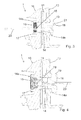
- FIG. 1 shows the assembly 1 from the direction of the reflector 13
- FIG. 2 shows the assembly 1 from the direction of the heat sink 10th
- the light assembly 1 comprises a heat sink 10, a support plate 11 for receiving LED bulbs 12 and a reflector 13.
- the light assembly 1 can serve to produce a main light function, such as a dipped beam, wherein the assembly shown 1 can also form only part of a light field or the light assembly serves to fulfill an additional or signal light function.
- the light assembly 1 is designed for receiving in the housing of a headlight, wherein the assembly 1 can be received, for example via the heat sink 10 to a corresponding attachment.
- the heat sink 10 has on a front side a substantially planar running receiving surface 10a, and on the receiving surface 10a is seated on a support plate 11.
- the carrier plate 11 may preferably be designed as a printed circuit board and at the same time de-heat the LED bulbs 12 so that heat generated during operation of the LED bulbs 12 can be dissipated through the carrier plate 11 into the heat sink 10. Consequently, the support plate 11 can preferably rest flush against the receiving surface 10a.
- a reflector 13 is seated, and the reflector 13 extends arcuately so above the light source 12, which irradiates this light with appropriate energization in the reflector 13.
- the support plate 11 and the reflector 13 is an arrangement of a spring element 15 and a tension member 16, wherein the tension member 16 in Fig. 1 is shown from the side of the reflector 13, and the spring element 15 is in Fig. 2 from the back of the heat sink 10 visible, noticeable.
- the structure and operation of the connecting means between the heat sink 10, the support plate 11 and the reflector 13 is in connection with the following 3 and 4 described in more detail.
- FIGS. 3 and 4 show a cross-sectional view through the light assembly 1, comprising the heat sink 10, the support plate 11 and the reflector 13.
- a common mounting opening 14 extends therethrough, and the mounting opening 14 extends between two mouth regions 14a and 14b.
- a first mouth region 14a is located in the heat sink 10, and an opposite second mouth region 14b is located in the reflector 13.
- a spring element configured as a helical spring is provided in the first mouth region 14a 15, wherein the spring element 15 comprises a collar 17 which engages around a corresponding, correspondingly designed inner part of the mouth region 14 of the heat sink 10.
- a tension element 16 which is designed in the manner of a cable tie 21, is introduced into the reflector 13 in the second opening region 14b.
- the tension element 16 comprises a plate 19 which is seated in the second opening region 14b in such a way that it floats over a molded shoulder on the plate 19 into a correspondingly configured flange in the mouth region 14b of the reflector 13.
- the tension member 16 further comprises a drawstring 20 which extends from the plate 19 out, and the drawstring 20 can be passed through a further opening in the plate 19 and locked in this.
- the tension member 16 is performed substantially in the manner of a cable tie.
- the tension band 20 of the tension element 16 is brought into contact with the spring element 15, as in FIG Fig. 4 shown.
- the spring element 15 has a central web 18 which is located at the opposite end of the end of the spring element 15 to which the collar 17 is attached. If the drawstring 20 is guided around the central web 18, then the drawstring 20 can subsequently be passed through the plate 19 and latched therein. To form a loop, which is guided around the central web 18 around, the drawstring 20 are now fed into the plate 19, whereby the spring element 15 lengthened. By the elongation of the spring element 15, a clamping force between the heat sink 10, the support plate 11 and the reflector 13 is generated, and the clamping force can be adjusted over the length of the drawstring 20 with which this is pulled through the plate 19 therethrough.
- connection shown between the heat sink 10, the support plate 11 and the reflector 13 is characterized in that only an axial force in the extension direction of the mounting hole 14 is applied.
- the connection is thus free of torque and transverse force, in particular by the central arrangement of the central web 18, the spring element 15 is not pulled obliquely. Due to the floating support of the plate 19 in the mouth region 14b of the reflector 13 transverse forces can be additionally avoided.
- Another advantage is that the tensioning force can be easily adjusted by the length of the drawstring 20, which is pulled back around the central web 18 by the plate 19 to form a loop. The adjustment can thus be done manually or with a gripper under force or preferably under a distance measurement.
Landscapes
- Engineering & Computer Science (AREA)
- General Engineering & Computer Science (AREA)
- Physics & Mathematics (AREA)
- Microelectronics & Electronic Packaging (AREA)
- Optics & Photonics (AREA)
- Mechanical Engineering (AREA)
- Non-Portable Lighting Devices Or Systems Thereof (AREA)
- Arrangement Of Elements, Cooling, Sealing, Or The Like Of Lighting Devices (AREA)
- Fastening Of Light Sources Or Lamp Holders (AREA)
Abstract
Description
- Die vorliegende Erfindung betrifft eine Lichtbaugruppe mit einem Kühlkörper, mit einer Trägerplatte zur Aufnahme wenigstens eines LED-Leuchtmittels und mit einem Reflektor, in den ein durch das LED-Leuchtmittel erzeugbares Licht einstrahlbar ist, wobei der Kühlkörper eine Aufnahmefläche aufweist, an der die Trägerplatte und der Reflektor aufeinander liegend angeordnet sind.
- Die
DE 10 2012 202 933 A1 zeigt eine Lichtbaugruppe mit einem Kühlkörper, mit einer Trägerplätte zur Aufnahme wenigstens eines LED-Leuchtmittels und mit einem Reflektor, in den ein durch das LED-Leuchtmittel erzeugbares Licht einstrahlbar ist. Der Kühlkörper weist eine Aufnahmefläche auf, an der die Trägerplatte und der Reflektor aufeinander liegend angeordnet sind. Um eine Verbindung des Reflektors mit der Trägerplatte und dem Kühlkörper zu schaffen, werden Schraubelemente verwendet. Werden die Schraubelemente festgezogen, so wird ein Drehmoment auf die zu verbindenden Bauteile aufgegeben, was zu einer Dejustage führen kann. Insbesondere dann, wenn die Trägerplatte mit den LED-Leuchtmitteln relativ zum Reflektor justiert ist, kann die einjustierte Position durch das Festziehen der Schraubelemente wieder verloren gehen. Daher ist eine drehmomentfreie Verbindung zwischen dem Kühlkörper, der Trägerplatte und dem Reflektor wünschenswert. - Aufgabe der Erfindung ist zur Überwindung der aus dem Stand der Technik hervorgehenden Nachteile die Bildung einer Lichtbaugruppe mit einem Kühlkörper, mit einer Trägerplatte und mit einem Reflektor, bei der die Trägerplatte mit dem Reflektor drehmomentfrei am Kühlkörper angeordnet werden sollen. Insbesondere soll bei einer Verbindung des Reflektors, der Trägerplatte und des Kühlkörpers eine Dejustage insbesondere von LED-Leuchtmitteln auf der Trägerplatte relativ zum Reflektor vermieden werden.
- Diese Aufgabe wird ausgehend von einer Lichtbaugruppe gemäß dem Oberbegriff des Anspruches 1 sowie gemäß dem Verfahren des Anspruches 8 mit den jeweils kennzeichnenden Merkmalen gelöst. Vorteilhafte Weiterbildungen der Erfindung sind in den abhängigen Ansprüchen angegeben.
- Zur Lösung der Aufgabe wird erfindungsgemäß vorgeschlagen, dass sich durch den Kühlkörper, die Trägerplatte und den Reflektor eine gemeinsame Montageöffnung erstreckt, in der ein Federelement und ein Zugelement angeordnet sind, wobei der Kühlkörper, die Trägerplatte und der Reflektor über das Federelement mit einer Vorspannkraft aufeinander liegend verspannt sind, und wobei die Verspannkraft mittels des Zugelementes auf das Federelement aufgebracht ist.
- Die Erfindung nutzt vorteilhaft die Möglichkeit, durch den Kühlkörper, die Trägerplatte und den Reflektor eine gemeinsame Montageöffnung einzubringen. Durch das Federelement und das Zugelement wird bei Aufbringung der Verspannkraft kein Drehmoment zwischen dem Reflektor und dem Kühlkörper bzw. der Trägerplatte erzeugt, so dass auch eine Dejustage der Trägerplatte mit den LED-Leuchtmitteln relativ zum Reflektor vermieden wird. Die Verspannkraft kann über das Zugelement eingestellt werden, wobei bei einer Längung des Federelementes ein im Wesentlichen linearer Kraftanstieg über einem Vorspannweg des Federelementes erzeugt wird. Hat die Verspannkraft einen Soll-Wert erreicht, indem das Federelement entsprechend vorgespannt wurde, so kann das Zugelement festgesetzt werden, so dass die Verspannkraft über das Federelement und das Zugelement für den Betrieb der Lichtbaugruppe dauerhaft aufrechterhalten bleibt.
- Das Leuchtmittel kann aus einer LED oder aus einem Laser gebildet sein oder das Leuchtmittel kann mehrere LEDs umfassen. Eine Ausführung des Leuchtmittels mit einer konventionellen Lichtquelle, beispielsweise mit einem thermischen Strahler oder einer Gasentladungslampe, ist im Rahmen der Erfindung ebenfalls möglich.
- Gemäß einer vorteilhaften Ausführungsform der Lichtbaugruppe kann die Montageöffnung sich gegenüberliegende Mündungsbereiche aufweisen, so dass ein erster Mündungsbereich beispielsweise im Kühlkörper liegt und ein gegenüberliegender zweiter Mündungsbereich liegt im Reflektor, und zwischen den beiden Mündungsbereichen erstreckt sich die Montageöffnung. Das Federelement kann dabei beispielsweise im ersten Mündungsbereich und das Zugelement im gegenüberliegenden zweiten Mündungsbereich einsitzen. Werden das Federelement und das Zugelement in die jeweiligen Mündungsbereiche eingebracht, können diese innenseitig in der Montageöffnung miteinander verbunden werden, wonach die Verspannkraft durch das Zugelement auf das Federelement aufgebracht wird.
- Das Federelement kann beispielsweise durch eine Schraubenfeder gebildet sein, und das Federelement kann einen ersten Endbereich mit einem Bund aufweisen, mit dem das Federelement im Mündungsbereich einsitzt. Weiterführend kann das Federelement, insbesondere die Schraubenfeder, einen zweiten Endbereich mit einem Mittelsteg aufweisen, an dem das Zugelement angebunden ist.
- Das Zugelement kann einen Teller aufweisen, mit dem das Zugelement im zweiten Mündungsbereich einsitzt und wobei das Zugelement ein Zugband aufweist, das um den Mittelsteg des Federelementes geführt ist. Insbesondere kann das Zugelement in Form eines Kabelbinders ausgebildet sein. Wird um den Mittelsteg mit dem Zugband eine Schlaufe gebildet, kann das Ende des Zugbandes wieder durch den Teller geführt werden, und nach Art eines Kabelbinders kann das Zugband am Teller festgezogen werden. Der eingezogene Bereich des Zugbandes wird dabei im Teller festgesetzt, und ist durch ein hinreichend weites Einziehen des Zugbandes in den Teller das Federelement entsprechend vorgespannt, so ist die Verbindungsanordnung des Kühlkörpers, der Trägerplatte und des Reflektors für den dauerhaften Einsatz fertiggestellt. Gegebenenfalls kann ein aus dem Teller herausragendes Ende des Zugbandes abgetrennt werden.
- Das Zugband kann im Teller des Zugelementes mit verschiedenen Bandlängen insbesondere nach Art des Kabelbinders verrastet sein, so dass beispielsweise über einen vorgegebenen Einzugweg des Zugbandes in den Teller die erforderliche Verspannkraft aufgebracht werden kann. Das Aufeinanderdrücken des Kühlkörpers, der Trägerplatte und des Reflektors erfolgt dabei über die Mündungsbereiche, indem der Teller beispielsweise im Mündungsbereich des Reflektors formschließend einsitzt und der Bund des Federelementes sitzt im Mündungsbereich des Kühlkörpers formschließend ein. Um seitliche Kräfte und Kippmomente zu vermeiden, kann der Teller beispielsweise schwimmend im Mündungsbereich des Reflektors einsitzen. Somit kann sich der Teller selbsttätig zur Mittelachse der Verspannkraft ausrichten, ohne dass das Zugband, also beispielsweise der Kabelbinder, das Federelement schräg zieht. Folglich erfolgt die Verbindung des Kühlkörpers mit der Trägerplatte und dem Reflektor nicht nur drehmomentfrei sondern auch frei von Kräften quer zur Führungsrichtung.
- Die Erfindung ist weiterhin gerichtet auf ein Verfahren zum Zusammenbau einer Lichtbaugruppe mit einem Kühlkörper, mit einer Trägerplatte zur Aufnahme wenigstens eines LED-Leuchtmittels und mit einem Reflektor, in den ein durch das LED-Leuchtmittel erzeugbares Licht einstrahlbar ist, wobei der Kühlkörper eine Aufnahmefläche aufweist, an der die Trägerplatte und der Reflektor aufeinander liegend angeordnet sind, wobei das Verfahren wenigstens die folgenden Schritte aufweist: Bereitstellen des Kühlkörpers, der Trägerplatte und des Reflektors in einer aufeinander liegenden Anordnung und mit einer gemeinsamen Montageöffnung; Einsetzen eines Federelementes und eines Zugelementes in die Montageöffnung und Aufbringen einer Verspannkraft mittels des Zugelementes auf das Federelement, so dass der Kühlkörper, die Trägerplatte und der Reflektor drehmomentfrei miteinander verbunden sind.
- Insbesondere kann sich die Montageöffnung zwischen zwei Mündungsbereichen erstrecken, wobei das Federelement in einen ersten Mündungsbereich eingesetzt wird und wobei das Zugelement in einen gegenüberliegenden zweiten Mündungsbereich der Montageöffnung eingesetzt wird. Das Federelement kann einen Bund umfassen, über den die Verspannkraft auf beispielsweise den Kühlkörper aufgebracht wird, und das Zugelement kann einen Teller aufweisen, der schwimmend im Mündungsbereich der Montageöffnung einsitzt, die sich abschnittsweise durch den Reflektor erstreckt.
- Gemäß einer vorteilhaften Ausgestaltung des erfindungsgemäßen Verfahrens kann das Zugelement ein Zugband aufweisen, wobei zur Aufbringung einer Verspannkraft mittels des Zugelementes auf das Federelement vorgesehen ist, dass das Zugband unter Bildung einer Schlaufe um einen Mittelsteg des Federelementes geführt wird und es ist vorgesehen, dass das Zugband anschließend nach Art eines Kabelbinders zugezogen wird, bis die gewünschte Verspannkraft erreicht wird. Das Federelement ist insbesondere als Schraubenfeder ausgeführt und weist auf einem ersten Ende den Bund auf, und auf dem gegenüberliegenden zweiten Ende weist die Schraubenfeder den Mittelsteg auf. Das Zugband kann nach Art eines Kabelbinders flexibel sein, damit dieses um den Mittelsteg des Federelementes insbesondere händisch herumgeführt wird. Anschließend wird das Ende des Zugbandes wieder durch eine Öffnung in den Teller des Zugelementes eingeführt, und das Einziehen des Zugbandes durch den Teller kann auf einer Länge erfolgen, die mit einer bekannten Verspannkraft korrespondiert. Somit kann die Verspannkraft über eine messbare Länge des Durchzugs des Zugbandes durch den Teller eingestellt werden. Das Federelement kann alternativ auch durch eine Spange gebildet sein, die im Mündungsbereich der Montageöffnung einsitzt oder das Federelement ist allgemein durch ein Biegeblech oder durch ein sonstiges Dehnelement gebildet. Wichtig und besonders vorteilhaft dabei ist, dass das Federelement und auch das Zugelement eine Anlage an einer Gegenanlage in den Mündungsbereichen der Montageöffnung bilden, die eine Anlageebene definieren, zu der die über das Federelement aufgebrachte Verspannkraft in einer Lotrechten verläuft.
- Weitere, die Erfindung verbessernde Maßnahmen werden nachstehend gemeinsam mit der Beschreibung eines bevorzugten Ausführungsbeispiels der Erfindung anhand der Figuren näher dargestellt. Es zeigt:
- Fig. 1
- eine perspektivische Ansicht der Lichtbaugruppe,
- Fig. 2
- eine weitere perspektivische Ansicht der Lichtbaugruppe,
- Fig. 3
- eine quergeschnittene Ansicht der Lichtbaugruppe mit einem Zugelement und einem Federelement in einer nicht verbundenen Anordnung und
- Fig. 4
- die quergeschnittene Ansicht gemäß
Fig. 3 mit einem Zugelement, das mit einem Federelement in Verbindung gebracht ist und das das Federelement mit einer Verspannkraft verspannt. - Die
Figuren 1 und 2 zeigen die erfindungsgemäße Lichtbaugruppe 1 in verschiedenen Perspektiven, undFigur 1 zeigt die Baugruppe 1 aus Richtung des Reflektors 13 undFigur 2 zeigt die Baugruppe 1 aus Richtung des Kühlkörpers 10. - Die Lichtbaugruppe 1 umfasst einen Kühlkörper 10, eine Trägerplatte 11 zur Aufnahme von LED-Leuchtmitteln 12 und einen Reflektor 13. Die Lichtbaugruppe 1 kann zur Erzeugung einer Hauptlichtfunktion dienen, beispielsweise eines Abblendlichtes, wobei die gezeigte Baugruppe 1 auch nur einen Teil eines Lichtfeldes bilden kann oder die Lichtbaugruppe dient zur Erfüllung einer Zusatz- oder Signallichtfunktion. Die Lichtbaugruppe 1 ist ausgeführt zur Aufnahme im Gehäuse eines Scheinwerfers, wobei die Baugruppe 1 beispielsweise über den Kühlkörper 10 an einer entsprechenden Befestigung aufgenommen werden kann.
- Der Kühlkörper 10 weist auf einer Vorderseite eine im Wesentlichen plan ausgeführte Aufnahmefläche 10a auf, und auf der Aufnahmefläche 10a sitzt eine Trägerplatte 11 auf. Die Trägerplatte 11 kann bevorzugt als Leiterplatte ausgeführt sein und zugleich die LED-Leuchtmittel 12 entwärmen, so dass Wärme, die im Betrieb der LED-Leuchtmittel 12 erzeugt wird, durch die Trägerplatte 11 in den Kühlkörper 10 abgeleitet werden kann. Folglich kann die Trägerplatte 11 bevorzugt plan an der Aufnahmefläche 10a anliegen. Auf der Vorderseite der Trägerplatte 11 sitzt ein Reflektor 13 auf, und der Reflektor 13 erstreckt sich bogenförmig so über dem Leuchtmittel 12, das dieses bei entsprechender Bestromung Licht in den Reflektor 13 einstrahlt.
- Zur Befestigung der Bauteile umfassend den Kühlkörper 10, die Trägerplatte 11 und den Reflektor 13 dient eine Anordnung aus einem Federelement 15 und einem Zugelement 16, wobei das Zugelement 16 in
Fig. 1 von der Seite des Reflektors 13 gezeigt ist, und das Federelement 15 ist inFig. 2 von der Rückseite des Kühlkörpers 10 sichtbar. Der Aufbau und die Funktionsweise des Verbindungsmittels zwischen dem Kühlkörper 10, der Trägerplatte 11 und dem Reflektor 13 ist in Zusammenhang mit den folgendenFig. 3 und 4 näher beschrieben. - Die
Figuren 3 und 4 zeigen eine Querschnittsansicht durch die Lichtbaugruppe 1, umfassend den Kühlkörper 10, die Trägerplatte 11 und den Reflektor 13. Durch den Kühlkörper 10, die Trägerplatte 11 und den Reflektor 13 erstreckt sich eine gemeinsame Montageöffnung 14 hindurch, und die Montageöffnung 14 verläuft zwischen zwei Mündungsbereichen 14a und 14b. Ein erster Mündungsberich 14a befindet sich im Kühlkörper 10, und ein gegenüberliegender zweiter Mündungsbereich 14b befindet sich im Reflektor 13. Um eine Verbindung zwischen dem Kühlkörper 10, der Trägerplatte 11 und dem Reflektor 13 zu schaffen, ist im ersten Mündungsbereich 14a ein als Schraubenfeder ausgeführtes Federelement 15 eingesetzt, wobei das Federelement 15 einen Bund 17 umfasst, der einen entsprechenden, korrespondierend ausgeführten inneren Teil des Mündungsbereiches 14 des Kühlkörpers 10 umgreift. Auf der gegenüberliegenden Seite ist im zweiten Mündungsbereich 14b im Reflektor 13 ein Zugelement 16 eingebracht, welches nach Art eines Kabelbinders 21 ausgeführt ist. Das Zugelement 16 umfasst einen Teller 19, der im zweiten Mündungsbereich 14b so einsitzt, dass dieser schwimmend über eine angeformte Schulter am Teller 19 in einen korrespondierend ausgeführten Bund im Mündungsbereich 14b des Reflektors 13 aufsitzt. Das Zugelement 16 umfasst weiterhin ein Zugband 20, das sich vom Teller 19 heraus erstreckt, und das Zugband 20 kann durch eine weitere Öffnung im Teller 19 hindurchgeführt und in diesem verrastet werden. Somit ist das Zugelement 16 im Wesentlichen nach Art eines Kabelbinders ausgeführt. - Zur Herstellung der Verbindung zwischen dem Kühlkörper 10, der Trägerplatte 11 und dem Reflektor 13 wird das Zugband 20 des Zugelementes 16 mit dem Federelement 15 in Verbindung gebracht, wie in
Fig. 4 gezeigt. Hierfür weist das Federelement 15 einen Mittelsteg 18 auf, der sich an dem gegenüberliegenden Ende des Endes des Federelementes 15 befindet, an dem der Bund 17 angebracht ist. Wird das Zugband 20 um den Mittelsteg 18 herumgeführt, so kann das Zugband 20 anschließend durch den Teller 19 hindurchgeführt und in diesem verrastet werden. Unter Bildung einer Schlaufe, die um den Mittelsteg 18 herum geführt ist, kann das Zugband 20 nunmehr in den Teller 19 eingezogen werden, wodurch sich das Federelement 15 längt. Durch die Längung des Federelementes 15 wird eine Verspannkraft zwischen dem Kühlkörper 10, der Trägerplatte 11 und dem Reflektor 13 erzeugt, und die Verspannkraft kann eingestellt werden über die Länge des Zugbandes 20, mit der dieses durch den Teller 19 hindurch gezogen wird. - Die gezeigte Verbindung zwischen dem Kühlkörper 10, der Trägerplatte 11 und dem Reflektor 13 zeichnet sich dadurch aus, dass ausschließlich eine Axialkraft in Erstreckungsrichtung der Montageöffnung 14 aufgebracht wird. Die Verbindung erfolgt folglich drehmoment- und querkraftfrei, insbesondere durch die mittige Anordnung des Mittelsteges 18 wird das Federelement 15 nicht schräg gezogen. Durch die schwimmende Auflage des Tellers 19 in dem Mündungsbereich 14b des Reflektors 13 können Querkräfte zusätzlich vermieden werden. Ein weiterer Vorteil besteht darin, dass die Verspannkraft einfach eingestellt werden kann durch die Länge des Zugbandes 20, das unter Bildung einer Schlaufe um den Mittelsteg 18 durch den Teller 19 zurückgezogen wird. Das Einstellen kann folglich manuell oder mit einem Greifer unter Kraftmessung oder bevorzugt unter einer Wegmessung erfolgen.
- Die Erfindung beschränkt sich in ihrer Ausführung nicht auf das vorstehend angegebene bevorzugte Ausführungsbeispiel. Vielmehr ist eine Anzahl von Varianten denkbar, welche von der dargestellten Lösung auch bei grundsätzlich anders gearteten Ausführungen Gebrauch macht. Sämtliche aus den Ansprüchen, der Beschreibung oder den Zeichnungen hervorgehenden Merkmale und/oder Vorteile, einschließlich konstruktiven Einzelheiten, räumlicher Anordnungen und Verfahrensschritte können sowohl für sich als auch in den verschiedensten Kombinationen erfindungswesentlich sein.
-
- 1
- Lichtbaugruppe
- 10
- Kühlkörper
- 10a
- Aufnahmefläche
- 11
- Trägerplatte
- 12
- Leuchtmittel
- 13
- Reflektor
- 14
- Montageöffnung
- 14a
- erster Mündungsbereich
- 14b
- zweiter Mündungsbereich
- 15
- Federelement
- 16
- Zugelement
- 17
- Bund
- 18
- Mittelsteg
- 19
- Teller
- 20
- Zugband
- 21
- Kabelbinder
Claims (10)
- Lichtbaugruppe (1) mit einem Kühlkörper (10), mit einer Trägerplatte (11) zur Aufnahme wenigstens eines Leuchtmittels (12) und mit einem Reflektor (13), in den ein durch das Leuchtmittel (12) erzeugbares Licht einstrahlbar ist, wobei der Kühlkörper (10) eine Aufnahmefläche (10a) aufweist, an der die Trägerplatte (11) und der Reflektor (13) aufeinander liegend angeordnet sind, dadurch gekennzeichnet, dass sich durch den Kühlkörper (10), die Trägerplatte (11) und den Reflektor (13) eine gemeinsame Montageöffnung (14) erstreckt, in der ein Federelement (15) und ein Zugelement (16) angeordnet sind, wobei der Kühlkörper (10), die Trägerplatte (11) und der Reflektor (13) über das Federelement (15) mit einer Verspannkraft aufeinander liegend verspannt sind, wobei die Verspannkraft mittels des Zugelementes (16) auf das Federelement (15) aufgebracht ist.
- Lichtbaugruppe (1) nach Anspruch 1, dadurch gekennzeichnet, dass die Montageöffnung (14) sich zwischen einem ersten Mündungsbereich (14a) und einen gegenüberliegenden zweiten Mündungsbereich (14b) erstreckt, wobei das Federelement (15) im ersten Mündungsbereich (14a) und das Zugelement (16) im gegenüberliegenden zweiten Mündungsbereich (14b) einsitzt.
- Lichtbaugruppe (1) nach Anspruch 1 oder 2, dadurch gekennzeichnet, dass das Federelement (15) durch eine Schraubenfeder gebildet ist und einen ersten Endbereich mit einem Bund (17) aufweist, mit dem das Federelement (15) im Mündungsbereich (14a) einsitzt.
- Lichtbaugruppe (1) nach einem der Ansprüche 1 bis 3, dadurch gekennzeichnet, dass das Federelement (15) einen zweiten Endbereich mit einem Mittelsteg (18) aufweist, an den das Zugelement (16) angebunden ist.
- Lichtbaugruppe (1) nach einem der vorgenannten Ansprüche, dadurch gekennzeichnet, dass das Zugelement (16) einen Teller (19) aufweist, mit dem das Zugelement (16) im zweiten Mündungsbereich (14b) einsitzt und wobei das Zugelement (16) ein Zugband (20) aufweist, das um den Mittelsteg (18) des Federelementes (15) geführt ist.
- Lichtbaugruppe (1) nach einem der vorgenannten Ansprüche, dadurch gekennzeichnet, dass das Zugelement (16) als Kabelbinder (21) ausgebildet ist.
- Lichtbaugruppe (1) nach einem der vorgenannten Ansprüche, dadurch gekennzeichnet, dass das Zugband (20) im Teller (19) des Zugelementes (16) bei verschiedenen Bandlängen nach Art eines Kabelbinders (21) verrastbar ist.
- Verfahren zum Zusammenbau einer Lichtbaugruppe (1) mit einem Kühlkörper (10), mit einer Trägerplatte (11) zur Aufnahme wenigstens eines Leuchtmittels (12) und mit einem Reflektor (13), in den ein durch das Leuchtmittel (12) erzeugbares Licht einstrahlbar ist, wobei der Kühlkörper (10) eine Aufnahmefläche (10a) aufweist, an der die Trägerplatte (11) und der Reflektor (13) aufeinander liegend angeordnet sind, wobei das Verfahren wenigstens die folgenden Schritte aufweist:- Bereitstellen des Kühlkörpers (10), der Trägerplatte (11) und des Reflektors (13) in einer aufeinander liegenden Anordnung und mit einer gemeinsamen Montageöffnung (14),- Einsetzen eines Federelementes (15) und eines Zugelementes (16) in einer gegenüberliegenden Anordnung in die Montageöffnung (14) und- Aufbringen einer Verspannkraft mittels des Zugelementes (16) auf das Federelement (15) senkrecht zur Aufnahmefläche (10a), sodass der Kühlkörper (10), die Trägerplatte (11) und der Reflektor (13) drehmomentfrei miteinander verbunden sind.
- Verfahren nach Anspruch 8, dadurch gekennzeichnet, dass sich die Montageöffnung (14) zwischen zwei Mündungsbereichen (14a, 14b) erstreckt, wobei das Federelement (15) in einen ersten Mündungsbereich (14a) und wobei das Zugelement (16) in einen gegenüberliegenden zweiten Mündungsbereich (14b) eingesetzt wird.
- Verfahren nach einem der Ansprüche 8 oder 9, dadurch gekennzeichnet, dass das Zugelement (16) ein Zugband (20) aufweist, wobei zur Aufbringung einer Verspannkraft mittels des Zugelementes (16) auf das Federelement (15) vorgesehen ist, dass- das Zugband (20) unter Bildung einer Schlaufe um einen Mittelsteg (18) des Federelementes (15) geführt wird und dass- das Zugband anschließend nach Art eines Kabelbinders (21) zugezogen wird, bis die gewünschte Verspannkraft erreicht ist.
Applications Claiming Priority (1)
| Application Number | Priority Date | Filing Date | Title |
|---|---|---|---|
| DE102014116684 | 2014-11-14 |
Publications (2)
| Publication Number | Publication Date |
|---|---|
| EP3021044A1 true EP3021044A1 (de) | 2016-05-18 |
| EP3021044B1 EP3021044B1 (de) | 2017-04-19 |
Family
ID=54705366
Family Applications (1)
| Application Number | Title | Priority Date | Filing Date |
|---|---|---|---|
| EP15194302.4A Active EP3021044B1 (de) | 2014-11-14 | 2015-11-12 | Lichtbaugruppe und verfahren zum drehmomentfreien zusammenbau der lichtbaugruppe |
Country Status (3)
| Country | Link |
|---|---|
| US (1) | US9772092B2 (de) |
| EP (1) | EP3021044B1 (de) |
| CN (1) | CN105605435B (de) |
Cited By (1)
| Publication number | Priority date | Publication date | Assignee | Title |
|---|---|---|---|---|
| EP3872395A1 (de) * | 2020-02-27 | 2021-09-01 | HELLA Saturnus Slovenija d.o.o. | Lichtmodul einer kraftfahrzeugbeleuchtungseinheit und verfahren zur montage eines lichtmoduls eines kraftfahrzeugs |
Families Citing this family (2)
| Publication number | Priority date | Publication date | Assignee | Title |
|---|---|---|---|---|
| DE102017115652A1 (de) | 2017-07-12 | 2019-01-17 | HELLA GmbH & Co. KGaA | Modulbaugruppe mit mehreren Lichteinheiten zur Anordnung in einer Beleuchtungseinrichtung |
| US10823356B1 (en) | 2019-12-20 | 2020-11-03 | Valeo Vision | Device and method of focusing a light |
Citations (6)
| Publication number | Priority date | Publication date | Assignee | Title |
|---|---|---|---|---|
| DE10224004A1 (de) * | 2001-06-11 | 2002-12-12 | Denso Corp | Entladungslampe für Fahrzeugscheinwerfer |
| US20100014287A1 (en) * | 2008-07-18 | 2010-01-21 | Foxsemicon Integrated Technology, Inc. | Illuminating device with heat dissipating element |
| US20110156567A1 (en) * | 2009-12-28 | 2011-06-30 | Silitek Electronic (Guangzhou) Co., Ltd. | Lamp and lamp holder module thereof |
| DE102011081062A1 (de) * | 2011-08-17 | 2013-02-21 | Automotive Lighting Reutlingen Gmbh | Scheinwerfer für ein Kraftfahrzeug mit einer auswechselbaren komplexen Lichtquelle |
| DE102012202933A1 (de) | 2012-02-27 | 2013-08-29 | Osram Gmbh | Beleuchtungseinrichtung |
| WO2014190368A1 (de) * | 2013-05-29 | 2014-12-04 | Zizala Lichtsysteme Gmbh | Beleuchtungsvorrichtung für einen fahrzeugscheinwerfer |
Family Cites Families (5)
| Publication number | Priority date | Publication date | Assignee | Title |
|---|---|---|---|---|
| US1911820A (en) * | 1929-08-09 | 1933-05-30 | Katches Inc | Fastening device |
| JP4535453B2 (ja) * | 2006-03-06 | 2010-09-01 | 株式会社小糸製作所 | 光源モジュール及び車輌用灯具 |
| DE102006048230B4 (de) * | 2006-10-11 | 2012-11-08 | Osram Ag | Leuchtdiodensystem, Verfahren zur Herstellung eines solchen und Hinterleuchtungseinrichtung |
| CN102149965B (zh) * | 2008-09-05 | 2016-08-31 | 皇家飞利浦电子股份有限公司 | 灯总成 |
| EP2182276B1 (de) * | 2008-10-31 | 2012-04-11 | Osram AG | Montageanordnung für Beleuchtungsmodule und entsprechendes Verfahren |
-
2015
- 2015-10-14 US US14/883,182 patent/US9772092B2/en active Active
- 2015-11-12 EP EP15194302.4A patent/EP3021044B1/de active Active
- 2015-11-13 CN CN201510777056.2A patent/CN105605435B/zh active Active
Patent Citations (6)
| Publication number | Priority date | Publication date | Assignee | Title |
|---|---|---|---|---|
| DE10224004A1 (de) * | 2001-06-11 | 2002-12-12 | Denso Corp | Entladungslampe für Fahrzeugscheinwerfer |
| US20100014287A1 (en) * | 2008-07-18 | 2010-01-21 | Foxsemicon Integrated Technology, Inc. | Illuminating device with heat dissipating element |
| US20110156567A1 (en) * | 2009-12-28 | 2011-06-30 | Silitek Electronic (Guangzhou) Co., Ltd. | Lamp and lamp holder module thereof |
| DE102011081062A1 (de) * | 2011-08-17 | 2013-02-21 | Automotive Lighting Reutlingen Gmbh | Scheinwerfer für ein Kraftfahrzeug mit einer auswechselbaren komplexen Lichtquelle |
| DE102012202933A1 (de) | 2012-02-27 | 2013-08-29 | Osram Gmbh | Beleuchtungseinrichtung |
| WO2014190368A1 (de) * | 2013-05-29 | 2014-12-04 | Zizala Lichtsysteme Gmbh | Beleuchtungsvorrichtung für einen fahrzeugscheinwerfer |
Cited By (1)
| Publication number | Priority date | Publication date | Assignee | Title |
|---|---|---|---|---|
| EP3872395A1 (de) * | 2020-02-27 | 2021-09-01 | HELLA Saturnus Slovenija d.o.o. | Lichtmodul einer kraftfahrzeugbeleuchtungseinheit und verfahren zur montage eines lichtmoduls eines kraftfahrzeugs |
Also Published As
| Publication number | Publication date |
|---|---|
| EP3021044B1 (de) | 2017-04-19 |
| US20160138786A1 (en) | 2016-05-19 |
| CN105605435A (zh) | 2016-05-25 |
| CN105605435B (zh) | 2018-12-04 |
| US9772092B2 (en) | 2017-09-26 |
Similar Documents
| Publication | Publication Date | Title |
|---|---|---|
| DE3313954A1 (de) | Plombe vom vorhaengeschlosstyp | |
| DE202017107545U1 (de) | Montageklammer | |
| DE102017108320B4 (de) | Flachteilhalter für die Befestigung eines Flachteils an einem Rahmengestell eines Schaltschranks und ein entsprechender Schaltschrank | |
| WO2011042195A1 (de) | Leuchteinheit für fahrzeuge | |
| DE102009022796A1 (de) | Vorrichtung zum Verlegen eines in einem Flugzeug installierten Kabelstrangs | |
| EP3021044B1 (de) | Lichtbaugruppe und verfahren zum drehmomentfreien zusammenbau der lichtbaugruppe | |
| DE102014104206A1 (de) | Befestigungsclip und Verfahren zum Herstellen eines Befestigungsclips | |
| DE19650864B4 (de) | Anordnung zur Befestigung einer Beleuchtungseinrichtung an einem Fahrzeugteil | |
| DE102010039133A1 (de) | Halterungsanordnung zur Halterung von Systemen sowie Luft- oder Raumfahrzeug | |
| EP3378700B1 (de) | Lichtmodul für einen kraftfahrzeugscheinwerfer | |
| DE102015118505B4 (de) | Befestigungsvorrichtung | |
| DE102011100888A1 (de) | Verbindungssystem mit einem Rohrverbinder | |
| DE1455395C3 (de) | Verfahren zur Herstellung einer isolierenden Schienenstoßverbindung | |
| DE102009010296A1 (de) | Verbindungsanordnung eines Anbauteils an einem Karosseriebauteil | |
| DE102019111429A1 (de) | Leuchteinheit für einen Scheinwerfer eines Fahrzeugs | |
| DE102012111312B4 (de) | Vorrichtung und Verfahren zum Justieren eines LED-Moduls | |
| EP3165821A1 (de) | Längliches lichtbandelement | |
| DE3147654A1 (de) | "waermeschutzschild oder -abschirmung fuer elektrische maschine" | |
| DE102023106842A1 (de) | Straffvorrichtung für eine Sicherheitsgurtkomponente | |
| DE102009024363A1 (de) | Vorrichtung zur Verbindung zweier Bauteile | |
| DE102004012049A1 (de) | Verfahren zum Befestigen eines Blechpaketes für die Statorwicklung eines Linearmotors am Fahrweg | |
| DE102013101340B4 (de) | Leuchteinheit mit einem Lichtleitkörper und Verfahren zur Montage einer Leuchteinheit | |
| DE102010000943B4 (de) | Leistungshalbleitermodul mit zwei miteinander verbundenen Gehäuseteilen und Verfahren zur Herstellung eines Leistungshalbleitermoduls mit zwei miteinander verbundenen Gehäuseteilen | |
| EP4340553B1 (de) | Elektronikmodul mit integrierter leiterplattenaufnahme zur kontaktierung zumindest eines drahtes mit einer in der leiterplattenaufnahme anordenbaren leiterplatte sowie zugehöriges verfahren | |
| DE102019126469A1 (de) | Steckverbinder zur modularen anordnung von kontakteinsätzen |
Legal Events
| Date | Code | Title | Description |
|---|---|---|---|
| PUAI | Public reference made under article 153(3) epc to a published international application that has entered the european phase |
Free format text: ORIGINAL CODE: 0009012 |
|
| AK | Designated contracting states |
Kind code of ref document: A1 Designated state(s): AL AT BE BG CH CY CZ DE DK EE ES FI FR GB GR HR HU IE IS IT LI LT LU LV MC MK MT NL NO PL PT RO RS SE SI SK SM TR |
|
| AX | Request for extension of the european patent |
Extension state: BA ME |
|
| 17P | Request for examination filed |
Effective date: 20160801 |
|
| RBV | Designated contracting states (corrected) |
Designated state(s): AL AT BE BG CH CY CZ DE DK EE ES FI FR GB GR HR HU IE IS IT LI LT LU LV MC MK MT NL NO PL PT RO RS SE SI SK SM TR |
|
| GRAP | Despatch of communication of intention to grant a patent |
Free format text: ORIGINAL CODE: EPIDOSNIGR1 |
|
| RIC1 | Information provided on ipc code assigned before grant |
Ipc: F21S 8/10 20060101ALI20161212BHEP Ipc: F21V 17/16 20060101AFI20161212BHEP Ipc: F21V 19/00 20060101ALI20161212BHEP |
|
| INTG | Intention to grant announced |
Effective date: 20170111 |
|
| GRAS | Grant fee paid |
Free format text: ORIGINAL CODE: EPIDOSNIGR3 |
|
| GRAA | (expected) grant |
Free format text: ORIGINAL CODE: 0009210 |
|
| AK | Designated contracting states |
Kind code of ref document: B1 Designated state(s): AL AT BE BG CH CY CZ DE DK EE ES FI FR GB GR HR HU IE IS IT LI LT LU LV MC MK MT NL NO PL PT RO RS SE SI SK SM TR |
|
| REG | Reference to a national code |
Ref country code: GB Ref legal event code: FG4D Free format text: NOT ENGLISH |
|
| REG | Reference to a national code |
Ref country code: CH Ref legal event code: EP |
|
| REG | Reference to a national code |
Ref country code: AT Ref legal event code: REF Ref document number: 886339 Country of ref document: AT Kind code of ref document: T Effective date: 20170515 |
|
| REG | Reference to a national code |
Ref country code: IE Ref legal event code: FG4D Free format text: LANGUAGE OF EP DOCUMENT: GERMAN |
|
| REG | Reference to a national code |
Ref country code: DE Ref legal event code: R096 Ref document number: 502015000894 Country of ref document: DE |
|
| REG | Reference to a national code |
Ref country code: NL Ref legal event code: MP Effective date: 20170419 |
|
| REG | Reference to a national code |
Ref country code: LT Ref legal event code: MG4D |
|
| PG25 | Lapsed in a contracting state [announced via postgrant information from national office to epo] |
Ref country code: NL Free format text: LAPSE BECAUSE OF FAILURE TO SUBMIT A TRANSLATION OF THE DESCRIPTION OR TO PAY THE FEE WITHIN THE PRESCRIBED TIME-LIMIT Effective date: 20170419 |
|
| REG | Reference to a national code |
Ref country code: FR Ref legal event code: PLFP Year of fee payment: 3 |
|
| PG25 | Lapsed in a contracting state [announced via postgrant information from national office to epo] |
Ref country code: NO Free format text: LAPSE BECAUSE OF FAILURE TO SUBMIT A TRANSLATION OF THE DESCRIPTION OR TO PAY THE FEE WITHIN THE PRESCRIBED TIME-LIMIT Effective date: 20170719 Ref country code: HR Free format text: LAPSE BECAUSE OF FAILURE TO SUBMIT A TRANSLATION OF THE DESCRIPTION OR TO PAY THE FEE WITHIN THE PRESCRIBED TIME-LIMIT Effective date: 20170419 Ref country code: FI Free format text: LAPSE BECAUSE OF FAILURE TO SUBMIT A TRANSLATION OF THE DESCRIPTION OR TO PAY THE FEE WITHIN THE PRESCRIBED TIME-LIMIT Effective date: 20170419 Ref country code: LT Free format text: LAPSE BECAUSE OF FAILURE TO SUBMIT A TRANSLATION OF THE DESCRIPTION OR TO PAY THE FEE WITHIN THE PRESCRIBED TIME-LIMIT Effective date: 20170419 Ref country code: GR Free format text: LAPSE BECAUSE OF FAILURE TO SUBMIT A TRANSLATION OF THE DESCRIPTION OR TO PAY THE FEE WITHIN THE PRESCRIBED TIME-LIMIT Effective date: 20170720 Ref country code: ES Free format text: LAPSE BECAUSE OF FAILURE TO SUBMIT A TRANSLATION OF THE DESCRIPTION OR TO PAY THE FEE WITHIN THE PRESCRIBED TIME-LIMIT Effective date: 20170419 |
|
| PG25 | Lapsed in a contracting state [announced via postgrant information from national office to epo] |
Ref country code: RS Free format text: LAPSE BECAUSE OF FAILURE TO SUBMIT A TRANSLATION OF THE DESCRIPTION OR TO PAY THE FEE WITHIN THE PRESCRIBED TIME-LIMIT Effective date: 20170419 Ref country code: PL Free format text: LAPSE BECAUSE OF FAILURE TO SUBMIT A TRANSLATION OF THE DESCRIPTION OR TO PAY THE FEE WITHIN THE PRESCRIBED TIME-LIMIT Effective date: 20170419 Ref country code: BG Free format text: LAPSE BECAUSE OF FAILURE TO SUBMIT A TRANSLATION OF THE DESCRIPTION OR TO PAY THE FEE WITHIN THE PRESCRIBED TIME-LIMIT Effective date: 20170719 Ref country code: IS Free format text: LAPSE BECAUSE OF FAILURE TO SUBMIT A TRANSLATION OF THE DESCRIPTION OR TO PAY THE FEE WITHIN THE PRESCRIBED TIME-LIMIT Effective date: 20170819 Ref country code: LV Free format text: LAPSE BECAUSE OF FAILURE TO SUBMIT A TRANSLATION OF THE DESCRIPTION OR TO PAY THE FEE WITHIN THE PRESCRIBED TIME-LIMIT Effective date: 20170419 Ref country code: SE Free format text: LAPSE BECAUSE OF FAILURE TO SUBMIT A TRANSLATION OF THE DESCRIPTION OR TO PAY THE FEE WITHIN THE PRESCRIBED TIME-LIMIT Effective date: 20170419 |
|
| REG | Reference to a national code |
Ref country code: DE Ref legal event code: R081 Ref document number: 502015000894 Country of ref document: DE Owner name: HELLA GMBH & CO. KGAA, DE Free format text: FORMER OWNER: HELLA KGAA HUECK & CO., 59557 LIPPSTADT, DE |
|
| REG | Reference to a national code |
Ref country code: DE Ref legal event code: R097 Ref document number: 502015000894 Country of ref document: DE |
|
| PG25 | Lapsed in a contracting state [announced via postgrant information from national office to epo] |
Ref country code: DK Free format text: LAPSE BECAUSE OF FAILURE TO SUBMIT A TRANSLATION OF THE DESCRIPTION OR TO PAY THE FEE WITHIN THE PRESCRIBED TIME-LIMIT Effective date: 20170419 Ref country code: CZ Free format text: LAPSE BECAUSE OF FAILURE TO SUBMIT A TRANSLATION OF THE DESCRIPTION OR TO PAY THE FEE WITHIN THE PRESCRIBED TIME-LIMIT Effective date: 20170419 Ref country code: EE Free format text: LAPSE BECAUSE OF FAILURE TO SUBMIT A TRANSLATION OF THE DESCRIPTION OR TO PAY THE FEE WITHIN THE PRESCRIBED TIME-LIMIT Effective date: 20170419 Ref country code: RO Free format text: LAPSE BECAUSE OF FAILURE TO SUBMIT A TRANSLATION OF THE DESCRIPTION OR TO PAY THE FEE WITHIN THE PRESCRIBED TIME-LIMIT Effective date: 20170419 Ref country code: SK Free format text: LAPSE BECAUSE OF FAILURE TO SUBMIT A TRANSLATION OF THE DESCRIPTION OR TO PAY THE FEE WITHIN THE PRESCRIBED TIME-LIMIT Effective date: 20170419 |
|
| PLBE | No opposition filed within time limit |
Free format text: ORIGINAL CODE: 0009261 |
|
| STAA | Information on the status of an ep patent application or granted ep patent |
Free format text: STATUS: NO OPPOSITION FILED WITHIN TIME LIMIT |
|
| PG25 | Lapsed in a contracting state [announced via postgrant information from national office to epo] |
Ref country code: IT Free format text: LAPSE BECAUSE OF FAILURE TO SUBMIT A TRANSLATION OF THE DESCRIPTION OR TO PAY THE FEE WITHIN THE PRESCRIBED TIME-LIMIT Effective date: 20170419 Ref country code: SM Free format text: LAPSE BECAUSE OF FAILURE TO SUBMIT A TRANSLATION OF THE DESCRIPTION OR TO PAY THE FEE WITHIN THE PRESCRIBED TIME-LIMIT Effective date: 20170419 |
|
| 26N | No opposition filed |
Effective date: 20180122 |
|
| PG25 | Lapsed in a contracting state [announced via postgrant information from national office to epo] |
Ref country code: SI Free format text: LAPSE BECAUSE OF FAILURE TO SUBMIT A TRANSLATION OF THE DESCRIPTION OR TO PAY THE FEE WITHIN THE PRESCRIBED TIME-LIMIT Effective date: 20170419 |
|
| PG25 | Lapsed in a contracting state [announced via postgrant information from national office to epo] |
Ref country code: MC Free format text: LAPSE BECAUSE OF FAILURE TO SUBMIT A TRANSLATION OF THE DESCRIPTION OR TO PAY THE FEE WITHIN THE PRESCRIBED TIME-LIMIT Effective date: 20170419 |
|
| PG25 | Lapsed in a contracting state [announced via postgrant information from national office to epo] |
Ref country code: LU Free format text: LAPSE BECAUSE OF NON-PAYMENT OF DUE FEES Effective date: 20171112 |
|
| REG | Reference to a national code |
Ref country code: BE Ref legal event code: MM Effective date: 20171130 |
|
| REG | Reference to a national code |
Ref country code: IE Ref legal event code: MM4A |
|
| PG25 | Lapsed in a contracting state [announced via postgrant information from national office to epo] |
Ref country code: MT Free format text: LAPSE BECAUSE OF FAILURE TO SUBMIT A TRANSLATION OF THE DESCRIPTION OR TO PAY THE FEE WITHIN THE PRESCRIBED TIME-LIMIT Effective date: 20170419 |
|
| REG | Reference to a national code |
Ref country code: FR Ref legal event code: PLFP Year of fee payment: 4 |
|
| PG25 | Lapsed in a contracting state [announced via postgrant information from national office to epo] |
Ref country code: IE Free format text: LAPSE BECAUSE OF NON-PAYMENT OF DUE FEES Effective date: 20171112 |
|
| PG25 | Lapsed in a contracting state [announced via postgrant information from national office to epo] |
Ref country code: BE Free format text: LAPSE BECAUSE OF NON-PAYMENT OF DUE FEES Effective date: 20171130 |
|
| PG25 | Lapsed in a contracting state [announced via postgrant information from national office to epo] |
Ref country code: HU Free format text: LAPSE BECAUSE OF FAILURE TO SUBMIT A TRANSLATION OF THE DESCRIPTION OR TO PAY THE FEE WITHIN THE PRESCRIBED TIME-LIMIT; INVALID AB INITIO Effective date: 20151112 |
|
| REG | Reference to a national code |
Ref country code: CH Ref legal event code: PL |
|
| PG25 | Lapsed in a contracting state [announced via postgrant information from national office to epo] |
Ref country code: CH Free format text: LAPSE BECAUSE OF NON-PAYMENT OF DUE FEES Effective date: 20181130 Ref country code: LI Free format text: LAPSE BECAUSE OF NON-PAYMENT OF DUE FEES Effective date: 20181130 |
|
| PG25 | Lapsed in a contracting state [announced via postgrant information from national office to epo] |
Ref country code: CY Free format text: LAPSE BECAUSE OF FAILURE TO SUBMIT A TRANSLATION OF THE DESCRIPTION OR TO PAY THE FEE WITHIN THE PRESCRIBED TIME-LIMIT Effective date: 20170419 |
|
| PG25 | Lapsed in a contracting state [announced via postgrant information from national office to epo] |
Ref country code: MK Free format text: LAPSE BECAUSE OF FAILURE TO SUBMIT A TRANSLATION OF THE DESCRIPTION OR TO PAY THE FEE WITHIN THE PRESCRIBED TIME-LIMIT Effective date: 20170419 |
|
| PG25 | Lapsed in a contracting state [announced via postgrant information from national office to epo] |
Ref country code: TR Free format text: LAPSE BECAUSE OF FAILURE TO SUBMIT A TRANSLATION OF THE DESCRIPTION OR TO PAY THE FEE WITHIN THE PRESCRIBED TIME-LIMIT Effective date: 20170419 |
|
| PG25 | Lapsed in a contracting state [announced via postgrant information from national office to epo] |
Ref country code: PT Free format text: LAPSE BECAUSE OF FAILURE TO SUBMIT A TRANSLATION OF THE DESCRIPTION OR TO PAY THE FEE WITHIN THE PRESCRIBED TIME-LIMIT Effective date: 20170419 |
|
| PG25 | Lapsed in a contracting state [announced via postgrant information from national office to epo] |
Ref country code: AL Free format text: LAPSE BECAUSE OF FAILURE TO SUBMIT A TRANSLATION OF THE DESCRIPTION OR TO PAY THE FEE WITHIN THE PRESCRIBED TIME-LIMIT Effective date: 20170419 |
|
| GBPC | Gb: european patent ceased through non-payment of renewal fee |
Effective date: 20191112 |
|
| PG25 | Lapsed in a contracting state [announced via postgrant information from national office to epo] |
Ref country code: GB Free format text: LAPSE BECAUSE OF NON-PAYMENT OF DUE FEES Effective date: 20191112 |
|
| REG | Reference to a national code |
Ref country code: AT Ref legal event code: MM01 Ref document number: 886339 Country of ref document: AT Kind code of ref document: T Effective date: 20201112 |
|
| PG25 | Lapsed in a contracting state [announced via postgrant information from national office to epo] |
Ref country code: AT Free format text: LAPSE BECAUSE OF NON-PAYMENT OF DUE FEES Effective date: 20201112 |
|
| PGFP | Annual fee paid to national office [announced via postgrant information from national office to epo] |
Ref country code: FR Payment date: 20250922 Year of fee payment: 11 |
|
| PGFP | Annual fee paid to national office [announced via postgrant information from national office to epo] |
Ref country code: DE Payment date: 20250916 Year of fee payment: 11 |