EP3020883A1 - System zur montage von wand- und/oder dachbedeckungsmaterialien und verfahren zur montage von wand- und/oder dachbedeckungen auf einer gebäudestruktur - Google Patents
System zur montage von wand- und/oder dachbedeckungsmaterialien und verfahren zur montage von wand- und/oder dachbedeckungen auf einer gebäudestruktur Download PDFInfo
- Publication number
- EP3020883A1 EP3020883A1 EP15194442.8A EP15194442A EP3020883A1 EP 3020883 A1 EP3020883 A1 EP 3020883A1 EP 15194442 A EP15194442 A EP 15194442A EP 3020883 A1 EP3020883 A1 EP 3020883A1
- Authority
- EP
- European Patent Office
- Prior art keywords
- mounting
- wall
- roof
- cladding
- lath
- Prior art date
- Legal status (The legal status is an assumption and is not a legal conclusion. Google has not performed a legal analysis and makes no representation as to the accuracy of the status listed.)
- Withdrawn
Links
Images


Classifications
-
- E—FIXED CONSTRUCTIONS
- E04—BUILDING
- E04D—ROOF COVERINGS; SKY-LIGHTS; GUTTERS; ROOF-WORKING TOOLS
- E04D12/00—Non-structural supports for roofing materials, e.g. battens, boards
- E04D12/004—Battens
-
- E—FIXED CONSTRUCTIONS
- E04—BUILDING
- E04D—ROOF COVERINGS; SKY-LIGHTS; GUTTERS; ROOF-WORKING TOOLS
- E04D1/00—Roof covering by making use of tiles, slates, shingles, or other small roofing elements
- E04D1/34—Fastenings for attaching roof-covering elements to the supporting elements
-
- E—FIXED CONSTRUCTIONS
- E04—BUILDING
- E04F—FINISHING WORK ON BUILDINGS, e.g. STAIRS, FLOORS
- E04F13/00—Coverings or linings, e.g. for walls or ceilings
- E04F13/07—Coverings or linings, e.g. for walls or ceilings composed of covering or lining elements; Sub-structures therefor; Fastening means therefor
- E04F13/08—Coverings or linings, e.g. for walls or ceilings composed of covering or lining elements; Sub-structures therefor; Fastening means therefor composed of a plurality of similar covering or lining elements
- E04F13/0801—Separate fastening elements
- E04F13/0803—Separate fastening elements with load-supporting elongated furring elements between wall and covering elements
- E04F13/081—Separate fastening elements with load-supporting elongated furring elements between wall and covering elements with additional fastening elements between furring elements and covering elements
- E04F13/083—Hooking means on the back side of the covering elements
-
- E—FIXED CONSTRUCTIONS
- E04—BUILDING
- E04D—ROOF COVERINGS; SKY-LIGHTS; GUTTERS; ROOF-WORKING TOOLS
- E04D1/00—Roof covering by making use of tiles, slates, shingles, or other small roofing elements
- E04D1/34—Fastenings for attaching roof-covering elements to the supporting elements
- E04D2001/3408—Fastenings for attaching roof-covering elements to the supporting elements characterised by the fastener type or material
- E04D2001/3414—Metal strips or sheet metal
-
- E—FIXED CONSTRUCTIONS
- E04—BUILDING
- E04D—ROOF COVERINGS; SKY-LIGHTS; GUTTERS; ROOF-WORKING TOOLS
- E04D1/00—Roof covering by making use of tiles, slates, shingles, or other small roofing elements
- E04D1/34—Fastenings for attaching roof-covering elements to the supporting elements
- E04D2001/347—Fastenings for attaching roof-covering elements to the supporting elements characterised by the fastening pattern
- E04D2001/3476—Fastenings for attaching roof-covering elements to the supporting elements characterised by the fastening pattern the fastening means taking hold directly on adjacent elements of the same row and fastening them simultaneously to the roof structure
Definitions
- the roof cladding will be referred to as shale plates or roofing plates, the invention, however, not being limited to shale plates, but also being useable for mounting of other roof cladding materials in the form of plate elements made from wood, ceramic materials, including tile, fibre cement, felt board-based materials and natural stone, including particularly shale, and other commonly occurring roof cladding materials used in sheet form.
- the roofing plates are preferably flat, but the system according to the invention can also be used for laying of corrugated plates, e.g. traditional fibre cement plates or other commonly known corrugated plates, e.g. made from metal, such as steel plates.
- the mounting system according to the invention is thus easy and quick to mount.
- the lath profiles can be placed very easily and very precisely at the necessary distance with very little tolerance and level when placed in the hook elements on the guide strips.
- the only prerequisite is that the guide strips are placed uniformly on the substructure, so that the bottom hook elements are placed in a horizontal row on the wall or roof structure.
- This way, the mounting of the roof and/or wall cladding becomes easy and quick, among other things because the building fitter no longer needs to measure distances and ensure that every single row of the roof cladding material is placed horizontally on the wall or roof structure.
- the hook-shaped elements of the guide strip are placed with a distance d corresponding to the distance between the L-shaped leg of the lath profile.
- the distance d between the hook-shaped elements is determined according to the type of roof, respectively wall, cladding and the size of the cladding plates, among other things the height h of the plates being deciding for the distance d between lath profiles, as a certain overlap is calculated between the roofing plates, respectively the wall cladding plates, over the lath profile.
- the guide strip as well as the lath profile are manufactured from metal, such as steel, including galvanised steel, light-alloy metal, e.g. aluminium or similar appropriate metals.
- the guide strip and/or the lath profile is coated with a plastic layer of e.g. polyethylene (PE), polypropylene (PP), polyester/polyethylene terephthalate (PET) and/or similar appropriate plastic types and/or combinations hereof, which will inhibit or completely prevent any corrosion of the metal parts of the mounting system.
- PE polyethylene
- PP polypropylene
- PET polyester/polyethylene terephthalate
- the mounting system preferably also comprises a sealing strip which is mountable on a further flange along the back side of the stop.
- the sealing strip prevents encroachment of water that may run "backwards" in between the overlapping plates of wall or roof cladding, e.g. during a storm or due to other weather conditions.
- a sealing strip or a packing strip in the form of a foam band e.g. made from polyether sulfone (PES) or alternatively a rubber-based sealing strip, e.g. made from butyl rubber, is preferably placed on the further flange behind the stop flange.
- the sealing strip can e.g.
- connection face is substantially perpendicular to the mounting flange.
- said flange comprised by the mounting face on the lath profile extends substantially perpendicular from the upper side of the mounting face along the upper edge of the mounting face.
- said lath profile is formed by two or more individual lath profile parts.
- Roof or wall cladding elements are then mounted on the mounting plate of the guide profile, so that the upper edge of the wall cladding elements is brought into contact with a flange that is inclined in relation to the upper side of the mounting face along the upper edge of the mounting face on the lath profile, and which constitutes a stop for the upper edge of the wall or roof cladding elements. Roof or wall cladding elements are fixed to the mounting face of the lath profiles using fixing means.
- the lower face of the lower support flange or the upper face of the spacing face are glued together using an adhesive to avoid displacements between the mounting guides, e.g. during gusts of wind.
- the method according to the invention preferably also comprises that a sealing strip is mounted along the back side of the stop, as described above.
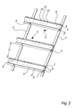
- Fig. 2 shows the roof mounting system according to the invention without roofing plates 1.
- the guide strip 2 has a number of sets of hook elements 4 placed with the distance D between each set of hook elements 4.
- the distance D is e.g. approx. 250 mm if the roofing plates 1 have a height H ( Fig. 1 ) of 300 mm.
- the distance d between the hook elements of each set is e.g. 50 mm, corresponding to the width of the lath profile 3 until the stop flange 9, i.e. without the area behind the stop 9.
- the lath profile 3 comprises a mounting face 6, on which the roofing plates, e.g. shale plates, are mounted using fixing means 14 in an area along the upper end of the roofing plates 1.
- the mounting face therefore preferably comprises a number of through-holes 13, designed for receiving the fixing means 14, e.g. screws.
- a sealing strip 15 is preferably mounted on the mounting face 6 in the area behind the stop 9.
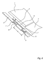
- Figs. 6 and 7a-7b show the location of the sealing plate 16 under a joint 18 between two neighbouring roofing plates 1.
- the sealing plate 16 has a fold 17 along its side edges.
- the sealing plate 16 is placed under a joint 18 between to neighbouring roofing plates 1 in a row, so that the joint 18 lies approximately along the centre line of the sealing plate 16, and so that the folds 17 face upwards in relation to the roofing plates 1, on which the sealing plate 16 strip is laid.
- the guide strip 2 and the lath profile 3 of the roof mounting system described above are also useful for mounting of facade cladding 1 on a wall of a building 5.
- the guide strip is mounted on a substructure on the wall face, e.g. a cover place and/or a post in the wall.
- the sealing plate 16 can be left out when mounting facade cladding on a wall.
- the mounting flange 8, 10 on the lath profile 3, 3' is also fixed using fixing means 19, e.g. screws, to the substructure. Therefore, the mounting flange 8, 10 on the lower of the L-shaped legs 7 of the lath profile is preferably also provided with holes (not shown) for fixing means which fix the lath profile 3 to the substructure in the wall structure.
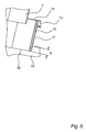
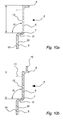
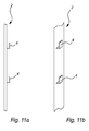
- Figs. 9a-9b and 10a-10b show variants of the lath profile 3'
- 10a-10b show variants of the lath profile 3' in cross-section.
- This lath profile 3' is suited for wall mounting of facade cladding material 1' in the form of plate-shaped facade cladding elements, as described in more detail above.
- the lath profile 3' comprises a mounting face 6, which along its lower edge has an L-shaped leg 7 with a mounting flange 8, 10. The angle between the connection flange in the L-shaped leg 7 and the mounting flange 8, 10 is substantially perpendicular.
- the stop flange 9 is substantially perpendicular to the upper side of the mounting face 6, as described above.
- the mounting face 6 is provided with a number of openings 13 for fixing means 14, which fix the facade cladding material 1' to the mounting face 6 of the lath profile.
- the number of the openings 13 and their individual distance can be varied in accordance with similar openings in the facade cladding plates 1'.
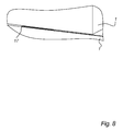
- Fig. 12a shows a cross-section through the lath profile 3' mounted with the guide strip in a cross-section through the longitudinal direction of the guide strip 2.
- the mounting flange 8, 10, 10 is placed between the surface of the guide strip 2 and the hook element 4.
Landscapes
- Engineering & Computer Science (AREA)
- Architecture (AREA)
- Civil Engineering (AREA)
- Structural Engineering (AREA)
- Mechanical Engineering (AREA)
- Roof Covering Using Slabs Or Stiff Sheets (AREA)
- Finishing Walls (AREA)
Applications Claiming Priority (2)
| Application Number | Priority Date | Filing Date | Title |
|---|---|---|---|
| DKPA201470702 | 2014-11-14 | ||
| DK201570058A DK178392B8 (da) | 2014-11-14 | 2015-02-02 | System til montering af væg- og/eller tagbeklædningsmaterialer og fremgangsmåde til montering af væg- og eller tagbeklædning på en bygningskonstruktion |
Publications (1)
| Publication Number | Publication Date |
|---|---|
| EP3020883A1 true EP3020883A1 (de) | 2016-05-18 |
Family
ID=54601624
Family Applications (1)
| Application Number | Title | Priority Date | Filing Date |
|---|---|---|---|
| EP15194442.8A Withdrawn EP3020883A1 (de) | 2014-11-14 | 2015-11-13 | System zur montage von wand- und/oder dachbedeckungsmaterialien und verfahren zur montage von wand- und/oder dachbedeckungen auf einer gebäudestruktur |
Country Status (2)
| Country | Link |
|---|---|
| EP (1) | EP3020883A1 (de) |
| DK (1) | DK178392B8 (de) |
Cited By (2)
| Publication number | Priority date | Publication date | Assignee | Title |
|---|---|---|---|---|
| EP3636853A1 (de) | 2018-10-12 | 2020-04-15 | Prodatek A/S | Montageschiene für montageverkleidung, verfahren zur verkleidung einer gebäudeoberfläche und verwendung einer montageschiene |
| CN116591401A (zh) * | 2023-07-17 | 2023-08-15 | 天合光能股份有限公司 | 光伏屋面 |
Citations (6)
| Publication number | Priority date | Publication date | Assignee | Title |
|---|---|---|---|---|
| US1725466A (en) * | 1926-08-30 | 1929-08-20 | Gladding Mcbean & Co | Roofing |
| DE7122693U (de) * | 1972-08-17 | Hunter D | Wandverkleidung bzw Zwischenprofil fur Wandverkleidungen | |
| FR2592673A1 (fr) * | 1986-01-07 | 1987-07-10 | Vicaire Bertrand | Chevron profile pour la pose de tuiles romaines |
| JPH04327635A (ja) * | 1991-04-26 | 1992-11-17 | Gantan Beauty Kogyo Kk | 屋根材用の捨て板 |
| WO2002033192A1 (en) * | 2000-10-17 | 2002-04-25 | Alan Zafer & Associates Limited | Slate laying system |
| US20030182888A1 (en) * | 2000-05-24 | 2003-10-02 | Christophe Desbois | Roof system with rows of superimposed tiles |
Family Cites Families (5)
| Publication number | Priority date | Publication date | Assignee | Title |
|---|---|---|---|---|
| NZ265219A (en) * | 1993-04-22 | 1997-08-22 | Richard Waddington | Tile roof fixing system has tiles supported by pairs of parallel joining strips sitting on battens on rafters |
| US5564245A (en) * | 1994-05-18 | 1996-10-15 | Rademacher; Richard J. | Hangers for siding |
| KR200158908Y1 (ko) * | 1997-09-08 | 1999-10-15 | 박준석 | 건축물 외장판재의 설치구조 |
| NZ588871A (en) * | 2010-10-28 | 2013-04-26 | Cladding Systems Internat Ltd | Cladding mounting rail and method for attaching angled lapped boards to an exterior wall. |
| US9624675B2 (en) * | 2013-01-27 | 2017-04-18 | Fiber Cement Foam Systems Insulation, LLC | Method and device to attach building siding boards |
-
2015
- 2015-02-02 DK DK201570058A patent/DK178392B8/da active
- 2015-11-13 EP EP15194442.8A patent/EP3020883A1/de not_active Withdrawn
Patent Citations (6)
| Publication number | Priority date | Publication date | Assignee | Title |
|---|---|---|---|---|
| DE7122693U (de) * | 1972-08-17 | Hunter D | Wandverkleidung bzw Zwischenprofil fur Wandverkleidungen | |
| US1725466A (en) * | 1926-08-30 | 1929-08-20 | Gladding Mcbean & Co | Roofing |
| FR2592673A1 (fr) * | 1986-01-07 | 1987-07-10 | Vicaire Bertrand | Chevron profile pour la pose de tuiles romaines |
| JPH04327635A (ja) * | 1991-04-26 | 1992-11-17 | Gantan Beauty Kogyo Kk | 屋根材用の捨て板 |
| US20030182888A1 (en) * | 2000-05-24 | 2003-10-02 | Christophe Desbois | Roof system with rows of superimposed tiles |
| WO2002033192A1 (en) * | 2000-10-17 | 2002-04-25 | Alan Zafer & Associates Limited | Slate laying system |
Cited By (3)
| Publication number | Priority date | Publication date | Assignee | Title |
|---|---|---|---|---|
| EP3636853A1 (de) | 2018-10-12 | 2020-04-15 | Prodatek A/S | Montageschiene für montageverkleidung, verfahren zur verkleidung einer gebäudeoberfläche und verwendung einer montageschiene |
| CN116591401A (zh) * | 2023-07-17 | 2023-08-15 | 天合光能股份有限公司 | 光伏屋面 |
| CN116591401B (zh) * | 2023-07-17 | 2023-10-20 | 天合光能股份有限公司 | 光伏屋面 |
Also Published As
| Publication number | Publication date |
|---|---|
| DK178392B1 (da) | 2016-02-01 |
| DK178392B8 (da) | 2016-04-04 |
Similar Documents
| Publication | Publication Date | Title |
|---|---|---|
| US10370855B2 (en) | Roof deck intake vent | |
| US8371083B2 (en) | Retrofit roof assembly | |
| WO2010128375A2 (en) | Profiled joint for connecting solar panels | |
| US8291655B2 (en) | Roof with ridge vent brace | |
| US20170306621A1 (en) | An exterior wall and a method for constructing an exterior wall | |
| US8522508B1 (en) | Flashing support cant for a wall assembly and associated method | |
| US20120291382A1 (en) | Cool roof batten assembly | |
| EP3020883A1 (de) | System zur montage von wand- und/oder dachbedeckungsmaterialien und verfahren zur montage von wand- und/oder dachbedeckungen auf einer gebäudestruktur | |
| GB2194265A (en) | Insulated roof cladding panels | |
| EP3075913B1 (de) | Verfahren zur reduktion der feuchteansammlung in einem hohlraum einer hohlraumwand und ein fundamentkeil | |
| MX2008003674A (es) | Sistema de techado y metodo. | |
| AU2019204459B2 (en) | A Roof | |
| JP6963985B2 (ja) | 外壁見切り部の防水構造とその形成方法 | |
| EP2126235B1 (de) | Brandschutzdachteilungssystem | |
| JP3233209U (ja) | 瓦屋根の下地構造 | |
| GB2502286A (en) | Roof panel with wooden skin layer and insulating layer. | |
| US9719260B2 (en) | Roof baffle | |
| EP2547834B1 (de) | Luftspaltbarriere | |
| JPS63284344A (ja) | 屋根パネル | |
| DK178993B1 (da) | Fremgangsmåde til etablering af en skotrende samt en skotrende | |
| FI59141B (fi) | Prefabricerat plaotbeslag foer anordnande av takgenomgaongar i takpanneklaedda yttertak | |
| CA2810153C (en) | Roof deck intake vent | |
| RU142711U1 (ru) | Крепежный узел | |
| JP6501337B2 (ja) | 屋根構造 | |
| WO2008003975A1 (en) | A cladding system |
Legal Events
| Date | Code | Title | Description |
|---|---|---|---|
| PUAI | Public reference made under article 153(3) epc to a published international application that has entered the european phase |
Free format text: ORIGINAL CODE: 0009012 |
|
| AK | Designated contracting states |
Kind code of ref document: A1 Designated state(s): AL AT BE BG CH CY CZ DE DK EE ES FI FR GB GR HR HU IE IS IT LI LT LU LV MC MK MT NL NO PL PT RO RS SE SI SK SM TR |
|
| AX | Request for extension of the european patent |
Extension state: BA ME |
|
| STAA | Information on the status of an ep patent application or granted ep patent |
Free format text: STATUS: THE APPLICATION IS DEEMED TO BE WITHDRAWN |
|
| 18D | Application deemed to be withdrawn |
Effective date: 20161119 |