Field of the invention
-
The present invention relates to a mounting system for mounting of a wall and/or a roof cladding on a building structure.
-
The invention furthermore relates to a method for mounting of a wall and/or roof cladding on a building structure.
Background of the invention
-
A building is normally erected by pouring an insulated foundation and subsequently placing external walls and inner walls, and the roof structure of the building is placed so that it is carried by at least the external walls. An underroof is then laid over the roof structure, such as diffusion-open underroof made from cloth or other known materials, plywood or masonite plates or other wooden cladding and similar types of underroof traditionally used in construction. Finally, the roof cladding is typically laid individually in the form of stone made from e.g. tile, cement-based materials or small flat plate-shaped elements made from materials that are e.g. wooden or ceramic, e.g. made from tile, felt board-based or from natural stone, e.g. shale. This type of flat cladding elements is also called shingles. Alternatively, larger plate-shaped materials are used, e.g. corrugated plates, including e.g. plates made from plastic or fibre cement, and the individual plates are fixed to a nailable plate-shaped substructure or to battens mounted on rafters in the roof structure.
-
Facade cladding which is mounted on existing facades or newly constructed buildings, can be mounted using several different known methods.
-
As regards building renovation, possibly in connection with external post-insulation of existing buildings, it is e.g. possible to mount facade claddings direcly on an existing facade by fixing the facade cladding directly to the vertical face of the facade, e.g. using screws or similar fixing means.
-
For instance,
US 2003/0182888 A describes a roof mounting system having horizontal lath profiles mounted on the roof using guide strips. The roof cladding is mounted by the cladding, on its back side, having one or more hooks at a distance from the lower edge adapted to support on a wing on the upper edge of the lath profile.
-
Alternatively, horizontal battens or guides are mounted, e.g. made from metal, plastic or wood, to which the facade cladding can be fixed, e.g. using screws or similar fixing means. The horizontal battens may be mounted directly on the facade face, or they may be mounted on vertical posts in the external wall, particularly in new construction. Alternatively, these posts are fixed to the existing facade, e.g. in connection with external post-insulation of existing buildings.
-
For instance, a first lower row of elements can be mounted in the facade cladding using fixing means, e.g. screws, along the upper end edge. The next row can be placed so that the lower end of the next row of facade cladding elements covers the upper edge of the underlying row of facade cladding elements. Hereby, the new row of facade cladding elements can also cover the fixing means of the previous row.
-
Common to these known systems is that each facade cladding element is mounted individually following time-consuming measurements. This means that the mounting of the cladding materials is very time-consuming and results in increased construction costs for the facade renovation or new building erection. Furthermore, the mounting is dependent on taking place in dry weather or under a covering of the building to avoid moisture behind the facade cladding.
Object of the invention
-
It is the object of the invention to provide a system and a method making it easy and quick to mount and fix plate-shaped wall and/or roof cladding elements on a building structure, thus reducing the costs for the mounting of the roof and/or wall cladding. It is furthermore the object of the invention to provide a system and a method for mounting of plate-shaped roof elements in a roof cladding, which save materials and thus result in reduced costs.
Description of the invention
-
These objects of the invention are achieved using a wall and/or roof cladding mounting system for mounting of a wall and/or roof cladding on a building structure. The mounting system comprises a lath profile having a mounting face for mounting of wall or roof cladding elements, wherein the lath profile along the lower edge of the mounting face comprises at least one first L-shaped leg. A mounting flange on the L-shaped leg is connected to the lower edge of the mounting face of the lath profile by a connection face which is inclined in relation to the mounting flange. The mounting face on the lath profile comprises a flange which is inclined in relation to the upper side of the mounting face along the upper edge of the mounting face, and which constitutes a stop for the upper edge of the wall or roof cladding elements. The mounting face of the lath profile comprises a number of holes for placing of fixing means for securing the upper end of the roof or wall cladding elements to the mounting face of the lath profile.
-
The roof or wall cladding elements are thus only retained on the lath profile at the fixing means along the upper edge of the roof or wall cladding elements, and cover against the row placed below at the lower end of the roof or wall cladding elements in the zone with overlap between the two rows of roof or wall cladding elements. This ensures that the mounting of the cladding elements on the lath profiles becomes invisible, uniform and very stable.
-
When mounting the roof or wall cladding elements on the mounting face of the lath profile, the above-mentioned flange thus constitutes a guide when the roof or wall cladding is mounted. In this way, the roof, respectively the wall, cladding is mounted uniformly on the lath profile, and thus the roof or the wall cladding is presented with a substantially straight line along the lower edge of a row of cladding elements overlapping the previous row of cladding elements.
-
Hereby it is achieved that it becomes very easy and very quick to lay a roof or set up a wall cladding on a building structure, comprising small plate-shaped roof or wall cladding materials of the above-mentioned type, e.g. shale plates.
-
In the following, the roof cladding will be referred to as shale plates or roofing plates, the invention, however, not being limited to shale plates, but also being useable for mounting of other roof cladding materials in the form of plate elements made from wood, ceramic materials, including tile, fibre cement, felt board-based materials and natural stone, including particularly shale, and other commonly occurring roof cladding materials used in sheet form. The roofing plates are preferably flat, but the system according to the invention can also be used for laying of corrugated plates, e.g. traditional fibre cement plates or other commonly known corrugated plates, e.g. made from metal, such as steel plates.
-
The roof structure itself comprises rafters designed to carry the roof. The roof structure is e.g. made from wood, which is traditionally used in housing construction, or the roof structure is a metal structure, e.g. made from steel, including galvanised steel or light-alloy metal, e.g. aluminium.
-
The wall structure comprises load-bearing posts and transversal battens. The wall structure is e.g. made from wood, which is traditionally used in housing construction, or is a metal structure, e.g. made from steel, including galvanised steel or light-alloy metal, e.g. aluminium, which may constitute the substructure for the mounting substructure for the mounting system according to the invention. The outside of the walls against the building envelope is possibly covered by a sheet material, e.g. plywood sheets, which can also be used as substructure for fixing of the mounting system according to the invention. In external post-insulation of an existing building, the existing external wall will be used to fix a structure which fixes the insulation between the previous external wall and the new building envelope. The new building envelope is e.g. mounted on the structure using the mounting system according to the invention.
-
It is preferred that the mounting system comprises a guide strip which is placeable on a rafter, and comprises hook-shaped elements with a distance between them, and wherein the hooks are adapted to engage a flange on a lath profile. The guide strip is mounted on the upper side of a rafter or on a wall face, such as on an existing wall face, a covering plate on a wall or directly on the posts of a wall structure. The mounting of the guide strip takes place using traditional fixing means, e.g. nails or screws, possibly in combination with an adhesive in the form of an adhesive strip on the back side of the guide strip, covered by a removeable piece of covering paper until the actual mounting. Alternatively, the guide strip can be fixed using rivets on a roof structure made from metal. The underroof may be fixed between the rafter and the guide strip or in another way.
-
The mounting system according to the invention is thus easy and quick to mount. The lath profiles can be placed very easily and very precisely at the necessary distance with very little tolerance and level when placed in the hook elements on the guide strips. The only prerequisite is that the guide strips are placed uniformly on the substructure, so that the bottom hook elements are placed in a horizontal row on the wall or roof structure. This way, the mounting of the roof and/or wall cladding becomes easy and quick, among other things because the building fitter no longer needs to measure distances and ensure that every single row of the roof cladding material is placed horizontally on the wall or roof structure. Once the measuring for the mounting of the guide strips has been done, and the guide strips are mounted, the entire roof, respectively wall, cladding will be mounted correctly and extremely quickly, as the fitter can merely place the lath profiles in the hooks of the guide strip, whereby they are automatically placed at the correct distance in relation to each other, as the distance between the hook elements of the guide strip is adapted to the size of the plate-shaped cladding elements and in consideration of the requirements to the load-bearing capacity of the mounting system. The roof, respectively the wall, cladding, will furthermore be presented aesthetically and is carried out correctly in correspondence with applicable construction specifications for the roof cladding in question. This also results in a significant reduction in the total costs for replacement or laying of a roof, as a significant part of the costs are made up by salary costs for the roof fitters.
-
If the wall or roof structure is made from metal, the guide strip may be integrated in the post or rafter structure, as the hook-shaped elements are thus designed in the upper faces of the rafters, respectively the surface of the posts, facing against the outside of the building.
-
However, it is preferred that the guide strip is an independent element, as that makes it possible to manufacture different guide strips adapted to the wall and/or roof cladding materials and having distances between the hook-shaped elements adapted to the size of the plates and the need for support, e.g. in a selected wall and/or roof cladding material. Thereby it is possible to manufacture rafters, respectively wall posts, independently of the choice of roof cladding. Furthermore, the guide strip can also be mounted on an existing wall or roof structure, where the cladding is to be replaced, and thus the new wall and/or roof cladding can quickly be mounted on an existing building.
-
The hook-shaped elements of the guide strip are placed with a distance d corresponding to the distance between the L-shaped leg of the lath profile. The distance d between the hook-shaped elements is determined according to the type of roof, respectively wall, cladding and the size of the cladding plates, among other things the height h of the plates being deciding for the distance d between lath profiles, as a certain overlap is calculated between the roofing plates, respectively the wall cladding plates, over the lath profile.
-
In a variant of the guide strip, this is designed with hook elements in pairs with a distance between the two hook elements of the pairs corresponding to the distance between the two L-shaped legs of the lath profile.
-
The hook elements on the guide strip are manufactured e.g. by a tab being punched out of the guide and pressed into hook form using an appropriate tool.
-
In a variant of the guide strip, two rows of hook elements are located in parallel in the longitudinal direction of the guide strip. This makes it possible to place any joints between the lath profiles over a rafter while at the same time fixing the ends of the two lath profiles in the joint.
-
The distance D between the lath profiles in a roof structure will e.g. be approx. 250 mm if for instance shale plates are used with a size of 300x300 mm and a thickness of 5-15 mm. According to the invention, an overlap h may exist, e.g. substantially corresponding to the width of the lath profile, which in this case would be approx. 50 mm.
-
The distance D' between the lath profiles when mounting wall cladding on a wall structure depends on the size of the selected wall cladding plates, a distance being chosen between the lath profiles which is slightly smaller than the height of the wall cladding plates, so that there is also an overlap between two rows of the wall cladding plates.
-
The lath profiles comprise a mounting face for fixing of the roofing plates on the lath profiles. The mounting face preferably has through-holes at a certain fixed distance, used for the fixing of the cladding elements using traditional fixing means, e.g. screws. By using a fixed distance, e.g. 75-100 mm, it will be possible to manufacture cladding elements for roofs and/or walls having pre-drilled holes at the fixed distance, so that it becomes easy and quick to mount the cladding elements.
-
The roofing plates or the wall cladding is mounted on the lath profile, so that their side faces abut each other, i.e. without overlap.
-
In order to avoid water encroachment between two neighbouring plates in a roof structure, a sealing plate is used, which will be described below. When the first row of roofing plates is fixed on a first lath profile, the overlap from the next row of roofing plates will cover the fixing means in the first row of roofing plates etc. The joint between the roofing plates in the second row is preferably displaced in relation to the previous row, so that the sealing plate (see below) can conduct any water encroaching into the joint between two neighbouring plates, down to an underlying plate in the row below.
-
The lath profile preferably comprises two L-shaped legs, wherein the lower flange is substantially parallel to the mounting face and is adapted to engage with the hook-shaped elements on the guide strip. The two L-shaped legs are fixed to the underside of the mounting face and parallel to the upper and the lower edge of the mounting face, respectively. In order to be able to engage with the hook elements on the guide strip, the lower flanges on the L-shaped legs face the same way and point downwards when they are mounted in the hook elements of the guide strip. The weight of the roof will thus assist in retaining the lath profiles in the hooks of the guide strip by virtue of its own weight, and it is easy to mount the lath profiles by pushing them down into the hook elements.
-
The lower mounting flange of the lath profile on the L-shaped legs preferably comprises a slot parallel to the longitudinal direction of the lath profile. The slot is destined for snap engagement with an edge on the back side of the hook-shaped elements. This ensures better retention of the lath profiles in the guide strip, on the one hand during the mounting hereof, as the parts do not as easily get separated, e.g. through a push or similar during the mounting, on the other hand also in the finished roof, respectively the finished wall cladding.
-
The lath profile is suited for manufacture by extrusion. The lath profile can be manufactured in lengths adapted to the relevant roof structure, so that the length is adapted to the distance between the rafters of the roof structure, or in standard lengths, e.g. between 900-6,000 mm.
-
The guide strip as well as the lath profile are manufactured from metal, such as steel, including galvanised steel, light-alloy metal, e.g. aluminium or similar appropriate metals. In one variant, the guide strip and/or the lath profile is coated with a plastic layer of e.g. polyethylene (PE), polypropylene (PP), polyester/polyethylene terephthalate (PET) and/or similar appropriate plastic types and/or combinations hereof, which will inhibit or completely prevent any corrosion of the metal parts of the mounting system.
-
The material thickness of the guide strip and particularly the lath profile depends of the weight of the cladding material mounted on the wall, respectively the roof, but will, in relation to a traditional wall, respectively roof, structure of wood be light, which improves the ergonomics for building workers, as the number of heavy lifts can be reduced significantly or avoided entirely.
-
A guide strip and a lath profile for mounting of a shale roof of shale plates having a size of 300x300 mm and a thickness of 5-15 mm will e.g. have a material thickness of 0.5-0.8 mm, preferably 0.6-0.7 mm.
-
The mounting system preferably also comprises a sealing strip which is mountable on a further flange along the back side of the stop. The sealing strip prevents encroachment of water that may run "backwards" in between the overlapping plates of wall or roof cladding, e.g. during a storm or due to other weather conditions. A sealing strip or a packing strip in the form of a foam band, e.g. made from polyether sulfone (PES) or alternatively a rubber-based sealing strip, e.g. made from butyl rubber, is preferably placed on the further flange behind the stop flange. The sealing strip can e.g. have a height that exceeds the height of the stop flange, so that the sealing strip is compressed under the weight of the roofing plate lying over the sealing strip and the stop. The sealing strip preferably comprises an adhesive strip which is placed against the further flange along the back side of the stop after having removed a cover strip, or the sealing strip is glued in place using another appropriate glue type, e.g. a separate piece of double adhesive tape or an appropriate liquid glue.
-
The mounting system preferably comprises a sealing plate, preferably in the form of a metal band, which along both its side edges comprises a fold for sealing between two neighbouring roofing plates. By letting the band have a fold along the side edges, it is prevented that water encroaching between two neighbouring roofing plates can encroach between two roofing plates and under the roof cladding. Instead, the water is conducted to a roofing plate in the row below etc. This minimises the risk of water damage arising and any problems with mildew and mould in the roof structure and in the building in general.
-
The sealing plate is preferably manufactured as a metal band of steel, aluminium or zink, possibly coated by a plastic layer of e.g. polyethylene (PE), polypropylene (PP), polyester/polyethylene terephthalate (PET) and/or similar appropriate plastic types and/or combinations hereof. The metal band e.g. has a material thickness of 0.05-0.4 mm, preferably 0.15-0.25 mm. The sealing plate can be supplied in lengths adapted to the height of the roofing plates used, whereby waste in the form of too short end pieces is avoided. Alternatively, the sealing plate is manufactured in lengths which can easily be shortened, e.g. by sawing or cutting a piece off the sealing plate of the desired length.
-
In an aspect of the invention the connection face is substantially perpendicular to the mounting flange.
-
In an aspect of the invention said flange comprised by the mounting face on the lath profile extends substantially perpendicular from the upper side of the mounting face along the upper edge of the mounting face.
-
In an aspect of the invention said lath profile is formed by two or more individual lath profile parts.
-
Forming the lath profile from two or more individual lath profile parts is advantageous in that it hereby is possible to form the lath profile from different material e.g. abated to the specific use.
-
The invention furthermore relates to a method for mounting of a wall and/or roof cladding on a building structure. The method comprises mounting of a guide strip with hook-shaped elements on a substructure. A lath profile is then mounted having a mounting face for mounting of wall or cladding elements and having at least one L-shaped leg, wherein the lower flange of the at least one L-shaped leg is led into the opening between the hook elements on the guide strip and the upper side of the guide strip and into engagement, such as snap engagement, as described above, with the hook-shaped elements on the guide strip. Roof or wall cladding elements are then mounted on the mounting plate of the guide profile, so that the upper edge of the wall cladding elements is brought into contact with a flange that is inclined in relation to the upper side of the mounting face along the upper edge of the mounting face on the lath profile, and which constitutes a stop for the upper edge of the wall or roof cladding elements. Roof or wall cladding elements are fixed to the mounting face of the lath profiles using fixing means.
-
It is preferred that an adhesive is laid between two overlapping rows of wall or roof cladding elements. This ensures that the cladding elements do not rattle against each other in heavy wind or possibly torn completely off during a storm. Furthermore, the adhesive contributes to ensuring the building envelope against water encroachment.
-
It is preferred that the lower face of the lower support flange or the upper face of the spacing face are glued together using an adhesive to avoid displacements between the mounting guides, e.g. during gusts of wind.
-
Preferably, an adhesive is used in the form of a double adhesive sealing strip or a packing strip in the form of a rubber or foam band having adhesive on both sides. The sealing strip is e.g. manufactured from a polyether sulfone (PES) rubber or a butyl rubber-based sealing strip, which can be compressed without flowing out under the pressure that occurs between the cladding plates when the outer of the two overlapping cladding plates is fixed to the lath profile. As an alternative hereto, an expanding glue type or sealant may be used, which can fill out a gap between the cladding plates.
-
The method preferably furthermore comprises laying a sealing plate between two neighbouring roof elements, the sealing plate along both its side edges comprising a fold, as described above.
-
The method according to the invention preferably also comprises that a sealing strip is mounted along the back side of the stop, as described above.
Description of the drawings
-
In the following, the invention will be described with reference to the drawings, wherein
- Fig. 1
- shows a roof made using a roof mounting system according to the invention,
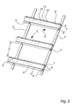
- Fig. 2
- shows the guide strip and lath profile of the roof mounting system without roof cladding,
- Fig. 3
- shows a detailed view of the guide strip and lath profile of the roof mounting system with roof cladding,
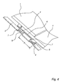
- Fig. 4
- shows a section through the joint between the guide strip and the lath profile, seen in perspective,
- Fig. 5
- shows a detailed view of the L-shaped leg of the lath profile mounted in the hook elements of the guide strip,
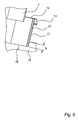
- Fig. 6
- shows the location of a sealing plate according to the invention,
- Figs. 7a-7b
- show the location of a sealing plate according to the invention in different enlargements,
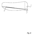
- Fig. 8
- shows the sealing plate between two roofing plates according to the invention,
- Figs. 9a-b
- show possible alternative designs of the lath profile which are well suited for mounting of facade cladding materials,
- Figs. 10a-b
- show a cross-section at A-A through the lath profile of Fig. 9a or 9b,
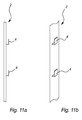
- Fig. 11a
- shows a variant of the guide strip, seen in cross-section and perspective,
- Fig. 11b
- shows a variant of the guide strip, seen in perspective,
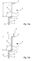
- Fig. 12a
- shows a cross-section of a lath profile mounted in a guide strip and mounted with facade cladding, and
- Fig. 12b
- shows a cross-section of a lath profile and mounted with facade cladding.
Detailed description of the invention
-
Fig. 1 shows a roof with a roof cladding in the form of individual roofing plates 1, mounted using a mounting system according to the invention. A number of guide strips 2 are mounted on the upper side of rafters in a roof structure (not shown). Perpendicularly to the guide strips 1, i.e. substantially horizontally, lath profiles 3 are mounted, to which the roofing plates 1 are fixed. The roofing plates 1 are placed in rows, so that a joint 18 between two neighbouring plates occurs. The second row of roofing plates 1 is mounted displaced in relation to the row below etc., so that the joint 18 on the second row lies in line with an area of a roofing plate 1 of the row below. Thereby the joints 18 between the roofing plates 1 do not lie directly in continuation of each other.
-
Fig. 2 shows the roof mounting system according to the invention without roofing plates 1. The guide strip 2 has a number of sets of hook elements 4 placed with the distance D between each set of hook elements 4. The distance D is e.g. approx. 250 mm if the roofing plates 1 have a height H (Fig. 1) of 300 mm. The distance d between the hook elements of each set is e.g. 50 mm, corresponding to the width of the lath profile 3 until the stop flange 9, i.e. without the area behind the stop 9. The lath profile 3 comprises a mounting face 6, on which the roofing plates, e.g. shale plates, are mounted using fixing means 14 in an area along the upper end of the roofing plates 1. The mounting face therefore preferably comprises a number of through-holes 13, designed for receiving the fixing means 14, e.g. screws. A sealing strip 15 is preferably mounted on the mounting face 6 in the area behind the stop 9.
-
The stop 9 has a height substantially corresponding to the thickness of a roofing plate 1.
-
The roofing plates 1 are laid with an overlap h, so that the next row of roofing plates 1 covers the area of the previous row of roofing plates 1 where the fixing means 14, e.g. screws, are located.
-
Figs. 4-5 show a section through the guide strip 2, the hooks 4 and the lath profile 3. The lath profile 3 has a mounting face 6, the upper side of which is substantially parallel to the plane of the guide strip 2. On the underside of the mounting face 6, two L-shaped legs 7 are fixed, wherein the lower flanges 8 are substantially parallel to the mounting face 6. The mounting flanges 8, 10 face the same way, i.e. downwards when they are mounted.
-
The lath profile is mounted in the guide strip 2 by the lower flanges 8 being snapped onto the hook elements 4 on the guide strips. A lath profile 3 extends over several guide strips 2, and the roof mounting system thus replaces the traditional wooden battens of a roof structure and is both quicker and easier to mount.
-
Figs. 6 and 7a-7b show the location of the sealing plate 16 under a joint 18 between two neighbouring roofing plates 1. The sealing plate 16 has a fold 17 along its side edges. The sealing plate 16 is placed under a joint 18 between to neighbouring roofing plates 1 in a row, so that the joint 18 lies approximately along the centre line of the sealing plate 16, and so that the folds 17 face upwards in relation to the roofing plates 1, on which the sealing plate 16 strip is laid.
-
In this way, the fold 17 will lie under the roofing plate 1, which prevents water encroachment under the roofing plates 1 and into the house. Any encroaching water will be conducted down the sealing plate 1 and onto the surface of the roofing plate 1 in the row below, because the joints 18 between the roofing plates 1 of a row are displaced in relation to the rows above and in relation to the row below the current row of roofing plates.
-
The guide strip 2 and the lath profile 3 of the roof mounting system described above are also useful for mounting of facade cladding 1 on a wall of a building 5. When mounting facade cladding on a wall, the guide strip is mounted on a substructure on the wall face, e.g. a cover place and/or a post in the wall. The sealing plate 16 can be left out when mounting facade cladding on a wall.
-
Figs. 11a-11b show a variant of the guide strip 2, which is useful for wall mounting of the mounting system in connection with mounting of facade cladding. The hook element 4 on the guide strip 2 is substantially as described above, however there are not two hook elements 4 per lath profile 3. Also on this variant of the guide strip 2, the hook elements 4 may be placed in two parallel rows (not shown) in the longitudinal direction, so that it becomes possible to abut the ends of two lath profiles 3 against each other and support the ends of the lath profiles 3 in each their hook element 4.
-
In wall mounting, it is preferred that the mounting flange 8, 10 on the lath profile 3, 3' is also fixed using fixing means 19, e.g. screws, to the substructure. Therefore, the mounting flange 8, 10 on the lower of the L-shaped legs 7 of the lath profile is preferably also provided with holes (not shown) for fixing means which fix the lath profile 3 to the substructure in the wall structure.
-
Figs. 9a-9b and 10a-10b show variants of the lath profile 3', and 10a-10b show variants of the lath profile 3' in cross-section. This lath profile 3' is suited for wall mounting of facade cladding material 1' in the form of plate-shaped facade cladding elements, as described in more detail above. The lath profile 3' comprises a mounting face 6, which along its lower edge has an L-shaped leg 7 with a mounting flange 8, 10. The angle between the connection flange in the L-shaped leg 7 and the mounting flange 8, 10 is substantially perpendicular. The angle α between the connection flange and the mounting face is preferably 86-89°, preferably 87-88.5°, so that the mounting face 6 and the mounting flange 8, 10 of the L-shaped leg is 1-4°. This makes it possible for each row of plate-shaped cladding elements 1 in a row mounted above to be oblique, so that the lower edge of the row of the plate-shaped cladding elements 1 on the lath profile 3 mounted above can thus overlap plate-shaped cladding elements 1 in the row below (see Figs. 11a-11b).
-
The mounting flange 8, 10 is provided with a number of through-holes 20 used to fix the lath profile 3' to the substructure in the wall.
-
Also in this variant of the lath profile 3', the stop flange 9 is substantially perpendicular to the upper side of the mounting face 6, as described above. The mounting face 6 is provided with a number of openings 13 for fixing means 14, which fix the facade cladding material 1' to the mounting face 6 of the lath profile. The number of the openings 13 and their individual distance can be varied in accordance with similar openings in the facade cladding plates 1'. Alternatively, the lath profiles 3' can be manufactured with a shorter or longer row of openings 13, so that it is possible to manufacture a single variant of the lath profile 3' which can be used for almost any type of facade cladding, as it is possible to select a number of appropriate openings that match the mounting openings in the facade cladding materials 1, regardless of the distance between them.
-
It is possible to provide the lath profile 3' with a further flange 19 along the back side of the stop 9, which e.g. constitutes an extension of the mounting face 6. This further flange 19 is used for mounting of the sealing strip 15, as described above.
-
In order to give the structure additional rigidity, the lath profile 3' may be provided with a support flange 21 which stands substantially perpendicular from the underside of the mounting face 6. The support flange 21 supports against the substructure, i.e. the outer surface of the wall, e.g. a cover plate.
-
Fig. 12a shows a cross-section through the lath profile 3' mounted with the guide strip in a cross-section through the longitudinal direction of the guide strip 2. The mounting flange 8, 10, 10 is placed between the surface of the guide strip 2 and the hook element 4.
-
Fig. 12b shows a cross-section through the lath profile 3' between two guide strips 2. Preferably, an adhesive strip or sealing strip 22 or glue is mounted as described above, which ensures that the plates of facade cladding 1 do not rattle against each other during heavy wind or are completely torn off, e.g. during a storm.
-
The mounting flange 8, 10 on the lath profile 3' is fixed to the substructure, i.e. the wall, using fixing means 23.
-
However, it is also possible to use the lath profiles 3, 3' without the use of guide strips 2, 2', but the mounting of the lath profiles 3, 3' is significantly quicker when guide strips are used, as the use of the guide strips 2, 2' avoids having to make measurements of the distance from the previous lath profile 3,3' and securing that the lath profile 3, 3' is level underway when placing every single lath profile 3, 3'. When using the guide strips 2, 2', it is only necessary to make measurements when mounting the guide strips 2, 2'.
List
-
- 1. Roofing plates
- 1'. Facade cladding material
- 2, 2'. Guide strip
- 3, 3'. Lath profiles
- 4. Hook elements
- 5. Building
- 6. Mounting face
- 7. L-shaped legs
- 8. Lower flanges
- 9. Stop flange
- 10. Mounting flange
- 11. Connection face
- 12.
- 13. Through holes
- 14. Fixing means
- 15. Sealing strip
- 16. Sealing plate
- 17. Fold of the sealing plate
- 18. Joint
- 19. Fixing means
- 20. Through-holes provided by the lower flange
- 21. Support flange
- 22. Sealing strip
- 23. Fixing means of the wall
- D. Distance between each set of hooks
- d. Distance between hook elements
- H. Height