EP3020643A2 - Stützvorrichtung für eine tasche - Google Patents
Stützvorrichtung für eine tasche Download PDFInfo
- Publication number
- EP3020643A2 EP3020643A2 EP14823765.4A EP14823765A EP3020643A2 EP 3020643 A2 EP3020643 A2 EP 3020643A2 EP 14823765 A EP14823765 A EP 14823765A EP 3020643 A2 EP3020643 A2 EP 3020643A2
- Authority
- EP
- European Patent Office
- Prior art keywords
- bag
- coupling portion
- mouth
- bag coupling
- pressing member
- Prior art date
- Legal status (The legal status is an assumption and is not a legal conclusion. Google has not performed a legal analysis and makes no representation as to the accuracy of the status listed.)
- Withdrawn
Links
- 230000008878 coupling Effects 0.000 claims abstract description 102
- 238000010168 coupling process Methods 0.000 claims abstract description 102
- 238000005859 coupling reaction Methods 0.000 claims abstract description 102
- 239000000463 material Substances 0.000 description 6
- 238000012856 packing Methods 0.000 description 5
- 238000005452 bending Methods 0.000 description 4
- 239000004033 plastic Substances 0.000 description 3
- 238000007789 sealing Methods 0.000 description 3
- 230000007423 decrease Effects 0.000 description 2
- 230000005489 elastic deformation Effects 0.000 description 2
- 230000000694 effects Effects 0.000 description 1
- 239000000835 fiber Substances 0.000 description 1
- 238000003780 insertion Methods 0.000 description 1
- 230000037431 insertion Effects 0.000 description 1
- 239000002184 metal Substances 0.000 description 1
- 238000000034 method Methods 0.000 description 1
- 238000012986 modification Methods 0.000 description 1
- 230000004048 modification Effects 0.000 description 1
- 239000000088 plastic resin Substances 0.000 description 1
- 229920001296 polysiloxane Polymers 0.000 description 1
- 238000000926 separation method Methods 0.000 description 1
- 229910052710 silicon Inorganic materials 0.000 description 1
- 239000010703 silicon Substances 0.000 description 1
- 239000000057 synthetic resin Substances 0.000 description 1
- 229920003002 synthetic resin Polymers 0.000 description 1
Images

Classifications
-
- B—PERFORMING OPERATIONS; TRANSPORTING
- B65—CONVEYING; PACKING; STORING; HANDLING THIN OR FILAMENTARY MATERIAL
- B65B—MACHINES, APPARATUS OR DEVICES FOR, OR METHODS OF, PACKAGING ARTICLES OR MATERIALS; UNPACKING
- B65B67/00—Apparatus or devices facilitating manual packaging operations; Sack holders
- B65B67/12—Sack holders, i.e. stands or frames with means for supporting sacks in the open condition to facilitate filling with articles or materials
-
- B—PERFORMING OPERATIONS; TRANSPORTING
- B65—CONVEYING; PACKING; STORING; HANDLING THIN OR FILAMENTARY MATERIAL
- B65F—GATHERING OR REMOVAL OF DOMESTIC OR LIKE REFUSE
- B65F1/00—Refuse receptacles; Accessories therefor
- B65F1/14—Other constructional features; Accessories
- B65F1/141—Supports, racks, stands, posts or the like for holding refuse receptacles
- B65F1/1415—Supports, racks, stands, posts or the like for holding refuse receptacles for flexible receptables, e.g. bags, sacks
-
- B—PERFORMING OPERATIONS; TRANSPORTING
- B65—CONVEYING; PACKING; STORING; HANDLING THIN OR FILAMENTARY MATERIAL
- B65B—MACHINES, APPARATUS OR DEVICES FOR, OR METHODS OF, PACKAGING ARTICLES OR MATERIALS; UNPACKING
- B65B67/00—Apparatus or devices facilitating manual packaging operations; Sack holders
- B65B67/12—Sack holders, i.e. stands or frames with means for supporting sacks in the open condition to facilitate filling with articles or materials
- B65B67/1255—Sack holders, i.e. stands or frames with means for supporting sacks in the open condition to facilitate filling with articles or materials characterised by positively acting means for stretching the mouth of the sack into the open condition, e.g. using springs
-
- B—PERFORMING OPERATIONS; TRANSPORTING
- B65—CONVEYING; PACKING; STORING; HANDLING THIN OR FILAMENTARY MATERIAL
- B65F—GATHERING OR REMOVAL OF DOMESTIC OR LIKE REFUSE
- B65F1/00—Refuse receptacles; Accessories therefor
-
- B—PERFORMING OPERATIONS; TRANSPORTING
- B65—CONVEYING; PACKING; STORING; HANDLING THIN OR FILAMENTARY MATERIAL
- B65F—GATHERING OR REMOVAL OF DOMESTIC OR LIKE REFUSE
- B65F1/00—Refuse receptacles; Accessories therefor
- B65F1/14—Other constructional features; Accessories
-
- B—PERFORMING OPERATIONS; TRANSPORTING
- B65—CONVEYING; PACKING; STORING; HANDLING THIN OR FILAMENTARY MATERIAL
- B65F—GATHERING OR REMOVAL OF DOMESTIC OR LIKE REFUSE
- B65F1/00—Refuse receptacles; Accessories therefor
- B65F1/14—Other constructional features; Accessories
- B65F1/16—Lids or covers
-
- F—MECHANICAL ENGINEERING; LIGHTING; HEATING; WEAPONS; BLASTING
- F16—ENGINEERING ELEMENTS AND UNITS; GENERAL MEASURES FOR PRODUCING AND MAINTAINING EFFECTIVE FUNCTIONING OF MACHINES OR INSTALLATIONS; THERMAL INSULATION IN GENERAL
- F16M—FRAMES, CASINGS OR BEDS OF ENGINES, MACHINES OR APPARATUS, NOT SPECIFIC TO ENGINES, MACHINES OR APPARATUS PROVIDED FOR ELSEWHERE; STANDS; SUPPORTS
- F16M11/00—Stands or trestles as supports for apparatus or articles placed thereon ; Stands for scientific apparatus such as gravitational force meters
- F16M11/20—Undercarriages with or without wheels
- F16M11/22—Undercarriages with or without wheels with approximately constant height, e.g. with constant length of column or of legs
-
- B—PERFORMING OPERATIONS; TRANSPORTING
- B65—CONVEYING; PACKING; STORING; HANDLING THIN OR FILAMENTARY MATERIAL
- B65F—GATHERING OR REMOVAL OF DOMESTIC OR LIKE REFUSE
- B65F1/00—Refuse receptacles; Accessories therefor
- B65F1/14—Other constructional features; Accessories
- B65F2001/1653—Constructional features of lids or covers
- B65F2001/1676—Constructional features of lids or covers relating to means for sealing the lid or cover, e.g. against escaping odors
-
- B—PERFORMING OPERATIONS; TRANSPORTING
- B65—CONVEYING; PACKING; STORING; HANDLING THIN OR FILAMENTARY MATERIAL
- B65F—GATHERING OR REMOVAL OF DOMESTIC OR LIKE REFUSE
- B65F2210/00—Equipment of refuse receptacles
- B65F2210/167—Sealing means
Definitions
- the present invention relates to a bag supporting device, and more particularly, to a bag supporting device that can open a mouth of a bag and support the bag or close the mouth of the bag.
- a plastic bag such as a garbage bag or a food garbage bag has a constant volume and is thrown away with a mouth thereof bound when the volume is full.
- the mouth of the garbage bag is opened, garbage is placed in the garbage bag, and then the mouth thereof is bound again until the volume is full.
- the mouth of the garbage bag does not need to be opened and bound again whenever garbage is placed in the garbage bag and thus the garbage bag can be conveniently used.
- bad smell from the garbage can be controlled and thus the garbage bag can be used sanitarily.
- the present invention is made to solve the above-mentioned problem and an object thereof is to provide a bag supporting device with a simple configuration which can be conveniently used.
- a bag supporting device including: a bag coupling portion that presses an inner surface of a mouth of a bag to the outside by shape deformation and brings the mouth of the bag into close contact with an outer surface thereof while keeping the mouth of the bag opened, wherein the bag coupling portion includes a through-hole that communicates with the mouth of the bag and a pressing member of which a part is reduced and enlarged.
- the bag supporting device may have one or more of the following embodiments.
- a frictional member may be disposed on an outer surface of the bag coupling portion.
- the bag coupling portion may be fixed to a position with a constant height by a support.
- a cover may be coupled to the bag coupling portion.
- a bag to be described below has a bag shape and can be formed of various materials such as synthetic resin, paper, silicone, and fiber.
- the side and the bottom of the bag can be formed as surfaces, but may be formed as nets having large or small holes formed therein.
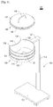
- FIGS. 1 to 5 a bag supporting device 100 according to a first embodiment of the present invention will be described with reference to FIGS. 1 to 5 .
- FIGS. 1 and 2 are perspective views illustrating the bag supporting device 100 according to the first embodiment of the present invention, where FIG. 1 illustrates a state in which a bag 170 and a cover 140 are not coupled to each other and FIG. 2 illustrates a state in which the bag 170 and the cover 140 are coupled to each other.
- the bag 170 is indicated by a dotted line for the purpose of convenience.
- the bag supporting device 100 includes a bag coupling portion 120 that is coupled to a mouth of the bag 170, a support 150 that supports the bag coupling portion 120 at a constant height, a base 160 that is coupled to an end of the support 150, and a cover 140 that is inserted into the bag coupling portion 120 and the bag 170.
- a part of the bag coupling portion 120 is elastically deformed and the outer diameter of the bag coupling portion 120 is enlarged or reduced by the deformation. Accordingly, when the bag 170 is inserted (which includes positioning the bag on the circumference of the bag coupling portion 120: the same is true in the following description) into the bag coupling portion 120 and then the outer diameter of the bag coupling portion 120 is enlarged as illustrated in FIG. 2 in a state in which the outer diameter of the bag coupling portion 120 is reduced as illustrated in FIG. 1 , the mouth of the bag 170 can be fixed to the outer surface 122 of the bag coupling portion 120. Accordingly, the bag 170 can be maintained in a constant shape while keeping the mouth opened by the bag coupling portion 120.
- the bag coupling portion 120 is coupled to the bag 170 by its elastic deformation, there is an advantage that the configuration thereof is simple. Since a user can insert the bag 170 into the bag coupling portion 120 in a state in which a pressing member 134 corresponding to a part of the bag coupling portion 120 is reduced as illustrated in FIG. 1 and then can elastically enlarge the pressing member 134 corresponding to a part of the bag coupling portion 120 as illustrated in FIG. 2 , there is also an advantage that the bag supporting device can be conveniently used.
- FIG. 3 is a plan view illustrating a state in which the pressing member 134 of the bag coupling portion 120 is reduced.
- FIG. 4 is a plan view illustrating a state in which the pressing member 134 of the bag coupling portion 120 illustrated in FIG. 3 is elastically deformed and enlarged to the outside.
- FIG. 5 is a cross-sectional view illustrating a state in which the cover 140 is coupled to the bag coupling portion 120 of the bag supporting device 100 illustrated in FIG. 1 .
- the mouth of the bag 170 is inserted onto the circumference of the outer surface 122 of the bag coupling portion 120.
- the bag coupling portion 120 includes the pressing member 134 and presses the inner surface of the mouth of the bag 170 to the outside by the elastic deformation of the pressing member 134 (enlargement to the outside in a state in which the pressing member is reduced inward). Accordingly, the bag 170 is fixed to a position around the outer surface 122 of the bag coupling portion 120 while keeping the mouth of the bag opened by the bag coupling portion 120.
- the bag coupling portion 120 has a cross-section having an elliptical shape and a through-hole 132 is formed at the center thereof.
- the bag coupling portion 120 has a constant height and includes an outer surface 122 and an inner surface 128. A part of the bag coupling portion 120 corresponds to the pressing member 134 which can be elastically deformed.
- the pressing member 134 can be formed of a material having elasticity such as plastic resin or metal, and is not limited to the materials as long as the pressing member has elasticity.
- the pressing member 134 formed as a part of the bag coupling portion 120 has elasticity and the shape can be elastically deformed.
- the pressing member 134 can be bent inward as in the state illustrated in FIG. 3 and can be elastically deformed to protrude outward as in the state illustrated in FIG. 4 .
- Bending points 136 formed to be thinner than the other portion are formed at both ends of the pressing member 134.
- the pressing member 134 can be bent about the bending points 136.
- the pressing member 134 may not include the bending points 136.
- the pressing member 134 may be formed of a material having elasticity and a potion other than the pressing member 134 may be formed of a material not having elasticity. Connecting portions between the pressing member 134 and the portion other than the pressing member 134 have a structure capable of allowing movement of the pressing member 134 when the pressing member 134 is pushed aside.
- the circumferential length of the bag coupling portion 120 is reduced and thus the bag 170 having a constant mouth size can be inserted onto the circumference of the bag coupling portion 120.
- the outer surface 122 of the bag coupling portion 120 may not press the inner surface of the mouth of the bag 170 outward.
- the circumferential length of the bag coupling portion 120 is enlarged. Accordingly, the outer surface 122 of the bag coupling portion 120 presses the inner surface of the mouth of the bag 170 outward and thus the bag 170 can come in close contact with and be fixed to the outer surface 122 of the bag coupling portion 120.
- the mouth of the bag 170 inserted onto the circumference of the bag coupling portion 120 may be deformed outward.
- the bag coupling portion 120 of the bag supporting device 100 according to the first embodiment has an elliptical cross-section, but the bag coupling portion of the bag supporting device according to the present invention is not limited to this shape. Accordingly, the bag coupling portion may have various shapes such as a circular shape or a polygonal shape.
- the pressing member 134 of the bag coupling portion 120 has an arc shape and one pressing member is disposed as a part of the bag coupling portion 120, but the shape and the number of pressing members are not limited to the above-mentioned examples.
- the pressing member may have a polygonal shape having two or more bending points and two or more pressing members may be disposed in the bag coupling portion 120.
- a frictional member 124 is formed on the outer surface 122 of the bag coupling portion 120.
- the frictional member 124 is formed along the circumference of the outer surface 122 of the bag coupling portion 120.
- the surface of the frictional member 124 has a frictional force and prevents the bag 170 closely contacting and fixed to the outer surface 122 of the bag coupling portion 120 from being easily detached therefrom.
- the frictional member 124 may be formed of a material having a frictional force such as rubber or silicon or may be embodied by a protrusion (not illustrated) or a groove (not illustrated) formed in a part of the outer surface 122 of the bag coupling portion 120 to give a frictional force.
- the frictional member 124 is present between the outer surface of the bag coupling portion 120 and the inner surface of the bag 170 and has a function of sealing the clearance therebetween. That is, the frictional member 124 has a packing function of preventing garbage smell from leaking therefrom.
- a rounded portion 126 curved to be inclined inward is formed at the lower end of the bag coupling portion 120.
- the rounded portion 126 enables easy insertion of the mouth of the bag 170 onto the circumference of the bag coupling portion 120.
- the inner surface 128 of the bag coupling portion 120 defines the through-hole 132.
- the through-hole 132 corresponds to a hole formed at the center of the bag coupling portion 120 and communicates with the bag 170 inserted onto the bag coupling portion 120 as illustrated in FIG. 2 .
- the bag coupling portion 120 and the bag 170 coupled thereto have a configuration similar to the configuration of a wastebasket, and the through-hole 132 of the bag coupling portion 120 corresponds to a mouth of the wastebasket.
- the bag coupling portion 120 has a constant height and has a constant coupling area to the bag 170 coming in close contact with the outer surface 122 thereof.
- the bag coupling portion 120 has a constant height due to the support 150.
- the support 150 is coupled to one top end portion of the bag coupling portion 120 and includes a horizontal member 152 and a vertical member 154.
- the vertical member 154 is provided to cause the bag coupling portion 120 to have a constant height from a base 160 located on the floor.
- the support 150 may have a structure (not illustrated) capable of adjusting the height and may adjust the height of the bag coupling portion 120.
- the base 160 is coupled to an end of the vertical member 154 and prevents the support 150 and the bag coupling portion 120 from falling.
- a member having a frictional force such as a rubber pad (not illustrated) may be coupled to the bottom surface of the base 160 so as to fix the position and to prevent sliding.
- the base 160 may have an adjustable base member (not illustrated) in which a contact surface with the floor can vary depending on a situation.
- the cover 140 is inserted into one of the bag coupling portion 120 and the bag 170 and serves to close the mouth thereof.
- FIG. 2 illustrates a state in which the cover 140 passes through the bag coupling portion 120 and is inserted into the bag 170.
- the cover 140 includes a cover body 142, a packing 144, and a knob 146.
- the cover body 142 has the same elliptical shape as the bag coupling portion 120 and the size may be slightly smaller than that of the bag coupling portion 120.
- the packing 144 is inserted into the circumference of the cover body 142 and the knob 146 is coupled to the top surface thereof.
- the cover 140 can be located inside the bag coupling portion 120 as illustrated in FIG. 5 .
- the packing 144 comes in close contact with the inner surface 128 of the bag coupling portion 120 to provide a sealing force. Accordingly, even when garbage (not illustrated) causing bad smell such as food garbage is placed in the bag 170, it is possible to prevent the bad smell from leaking outward by the cover 140.
- the cover 140 may pass through the bag coupling portion 120 and may be located inside the bag 170. In this case, an amount of garbage placed in the bag 170 is small.
- the packing 144 comes in close contact with the inner surface of the bag 170 to provide a sealing force.
- the knob 146 enables easy separation of the cover 140 from the bag 170 or the bag coupling portion 120.
- the cover 140 according to this embodiment can be inserted into the bag 170 through the bag coupling portion 120, but the cover may have a structure which is hooked to the top of the bag coupling portion 120 and does not pass through the bag coupling portion 120 in another embodiment.
- the pressing member 134 of the bag coupling portion 120 is bent inward as illustrated in FIGS. 1 and 3 . Accordingly, the circumferential length of the bag coupling portion 120 decreases and the bag 170 having a constant mouth size can be easily inserted onto the bag coupling portion 120.
- the bag 170 is inserted onto the bag coupling portion 120 from down to up. Since the rounded portion 126 is formed at the bottom of the bag coupling portion 120, the mouth of the bag 170 can be easily inserted onto the bag coupling portion 120.
- the pressing member 134 is bent outward as illustrated in FIGS. 2 and 4 . Since the pressing member 134 has elasticity, the pressing member can be deformed outward with its elasticity by only pulling the pressing member outward. When the pressing member 134 is deformed outward as illustrated in FIGS. 2 and 4 , the outer surface 122 of the bag coupling portion 120 presses the inner circumference of the mouth of the bag 170 outward. Accordingly, the bag 170 is brought into close contact with the circumference of the bag coupling portion 120 and fixed thereto and the mouth thereof can be kept opened by the bag coupling portion 120.
- the state illustrated in FIG. 2 is obtained by coupling the bag 170 to the bag coupling portion 120.
- a user can easily place garbage in the bag 170 of which the mouth is opened by the bag coupling portion 120.
- the mouth of the bag 170 can be closed using the cover 140.
- the pressing member 134 When the bag 170 is filled with garbage to a certain extent, the pressing member 134 is bent inward in the state illustrated in FIGS. 2 and 4 as illustrated in FIGS. 1 and 2 . Accordingly, the bag coupling portion 120 pressing the inner circumference of the mouth of the bag 170 outward decreases in the circumferential length. Accordingly, it is possible to easily separate the bag 170 from the bag coupling portion 120.
Landscapes
- Engineering & Computer Science (AREA)
- Mechanical Engineering (AREA)
- General Engineering & Computer Science (AREA)
- Refuse Receptacles (AREA)
- Bag Frames (AREA)
- Supplying Of Containers To The Packaging Station (AREA)
- Sheets, Magazines, And Separation Thereof (AREA)
- Auxiliary Apparatuses For Manual Packaging Operations (AREA)
Applications Claiming Priority (2)
| Application Number | Priority Date | Filing Date | Title |
|---|---|---|---|
| KR1020130081702A KR101390006B1 (ko) | 2013-07-11 | 2013-07-11 | 봉투 지지장치 |
| PCT/KR2014/006233 WO2015005710A2 (ko) | 2013-07-11 | 2014-07-11 | 봉투 지지장치 |
Publications (2)
| Publication Number | Publication Date |
|---|---|
| EP3020643A2 true EP3020643A2 (de) | 2016-05-18 |
| EP3020643A4 EP3020643A4 (de) | 2017-02-08 |
Family
ID=50658903
Family Applications (1)
| Application Number | Title | Priority Date | Filing Date |
|---|---|---|---|
| EP14823765.4A Withdrawn EP3020643A4 (de) | 2013-07-11 | 2014-07-11 | Stützvorrichtung für eine tasche |
Country Status (8)
| Country | Link |
|---|---|
| US (1) | US9676550B2 (de) |
| EP (1) | EP3020643A4 (de) |
| JP (1) | JP2016523787A (de) |
| KR (1) | KR101390006B1 (de) |
| CN (1) | CN105555670A (de) |
| AU (1) | AU2014287919B2 (de) |
| CA (1) | CA2916933A1 (de) |
| WO (1) | WO2015005710A2 (de) |
Families Citing this family (4)
| Publication number | Priority date | Publication date | Assignee | Title |
|---|---|---|---|---|
| KR101799649B1 (ko) * | 2015-12-07 | 2017-11-22 | 강희연 | 봉투를 묶어주는 쓰레기수거대 |
| CN111186668B (zh) * | 2020-03-31 | 2021-05-21 | 南通利安健智能科技有限公司 | 一种垃圾袋撑袋机构 |
| US11358791B1 (en) * | 2020-12-07 | 2022-06-14 | Owen Lee Alberson | EZ fill bag holder |
| KR102531360B1 (ko) * | 2023-04-07 | 2023-05-12 | 민서은 | 쓰레기봉투 거치대 |
Family Cites Families (33)
| Publication number | Priority date | Publication date | Assignee | Title |
|---|---|---|---|---|
| US224318A (en) * | 1880-02-10 | Bag-holder | ||
| US1468709A (en) * | 1922-03-06 | 1923-09-25 | Grandeur Alfred J La | Bag-mouth expander |
| US1922938A (en) * | 1931-11-05 | 1933-08-15 | William B Phillips | Bag holder |
| US2162113A (en) * | 1937-07-03 | 1939-06-13 | Fred P Noffsinger | Bag holder |
| US2383366A (en) * | 1943-07-05 | 1945-08-21 | Fmc Corp | Bag holder |
| US2995329A (en) * | 1960-09-02 | 1961-08-08 | Jr Louie R Talcott | Sack holder |
| US3142465A (en) * | 1961-06-19 | 1964-07-28 | Hellner Karl Gustaf | Supporting means for bags or sacks |
| US3768763A (en) * | 1971-03-11 | 1973-10-30 | R Hembree | Supporting device for open topped receptacle |
| GB2111937B (en) * | 1981-12-07 | 1985-07-10 | Ass Sprayers Ltd | A bag holder |
| JPS61200310U (de) * | 1985-06-05 | 1986-12-15 | ||
| DE8907061U1 (de) * | 1989-06-09 | 1989-10-05 | Löbbert, Johannes, 48301 Nottuln | Sack mit Sackkragen und Deckel |
| CA2001175C (en) * | 1989-10-20 | 1996-10-29 | Patrick J. Larkin | Garbage bag and utility holder |
| JPH0449103U (de) * | 1990-08-28 | 1992-04-24 | ||
| US5478152A (en) * | 1992-12-14 | 1995-12-26 | Bogle; David M. | Locking system for holding open a plastic film bag |
| CN2199138Y (zh) * | 1994-04-19 | 1995-05-31 | 高巍 | 方便架 |
| US20010032911A1 (en) * | 1998-04-24 | 2001-10-25 | Gabl Frank S. | Adjustable device for maintaining yard waste bags in open positions |
| JP2000168902A (ja) * | 1998-12-07 | 2000-06-20 | Tadashi Shiozawa | 臭い漏れ防止生ゴミ容器 |
| US6367822B1 (en) * | 2000-07-11 | 2002-04-09 | William B. Hutchins | Bag expander |
| US6554810B1 (en) * | 2000-07-12 | 2003-04-29 | Peter J. Wilk | Collapsible emesis container |
| US6431503B1 (en) * | 2001-08-24 | 2002-08-13 | Tom Horan | Lawn bag holder |
| US6705575B1 (en) * | 2003-01-17 | 2004-03-16 | Marian A. Hoy | Disposable bag with stand |
| US6698474B1 (en) * | 2003-03-07 | 2004-03-02 | William J. Trsek | Bag handling apparatus |
| KR200355078Y1 (ko) * | 2004-04-21 | 2004-07-02 | 이태희 | 쓰레기 봉투 거치대 |
| KR200362972Y1 (ko) * | 2004-07-12 | 2004-09-22 | 송원순 | 쓰레기 봉투 지지장치 |
| US7350547B2 (en) * | 2005-04-19 | 2008-04-01 | Quiring Frank K | Refuse bag tensioner and method of use |
| JP2007314296A (ja) * | 2006-05-25 | 2007-12-06 | Takeda:Kk | ごみ収納補助具 |
| KR20090006309U (ko) * | 2007-12-21 | 2009-06-25 | 임흥호 | 쓰레기봉투 거치구 |
| JP3155847U (ja) * | 2009-09-23 | 2009-12-03 | 有限会社 新美工業 | ゴミ袋保持具及びこれを用いたゴミ容器 |
| US8100370B1 (en) * | 2010-07-08 | 2012-01-24 | Ross Robert Kramer | Bag mouth holder and opener |
| CN201971361U (zh) * | 2010-12-25 | 2011-09-14 | 王昀 | 多功能长槽齿口式垃圾桶 |
| CN202124255U (zh) * | 2011-06-26 | 2012-01-25 | 谭全清 | 塑料袋活动垃圾筐架 |
| KR101107781B1 (ko) * | 2011-09-08 | 2012-01-25 | 신재민 | 투입구 가변형 종량제 쓰레기봉투 거치장치 |
| MX377303B (es) * | 2013-04-23 | 2025-03-07 | Vishaal Boehm Verma | Dispositivo para mantener abierto y empaque que tiene el mismo. |
-
2013
- 2013-07-11 KR KR1020130081702A patent/KR101390006B1/ko not_active Expired - Fee Related
-
2014
- 2014-07-11 JP JP2016525288A patent/JP2016523787A/ja active Pending
- 2014-07-11 EP EP14823765.4A patent/EP3020643A4/de not_active Withdrawn
- 2014-07-11 CA CA2916933A patent/CA2916933A1/en not_active Abandoned
- 2014-07-11 US US14/900,615 patent/US9676550B2/en not_active Expired - Fee Related
- 2014-07-11 CN CN201480038822.7A patent/CN105555670A/zh active Pending
- 2014-07-11 AU AU2014287919A patent/AU2014287919B2/en not_active Expired - Fee Related
- 2014-07-11 WO PCT/KR2014/006233 patent/WO2015005710A2/ko not_active Ceased
Non-Patent Citations (1)
| Title |
|---|
| See references of WO2015005710A2 * |
Also Published As
| Publication number | Publication date |
|---|---|
| US20160376100A1 (en) | 2016-12-29 |
| KR101390006B1 (ko) | 2014-04-30 |
| CA2916933A1 (en) | 2015-01-15 |
| EP3020643A4 (de) | 2017-02-08 |
| JP2016523787A (ja) | 2016-08-12 |
| WO2015005710A3 (ko) | 2015-03-26 |
| CN105555670A (zh) | 2016-05-04 |
| AU2014287919A1 (en) | 2016-02-04 |
| AU2014287919B2 (en) | 2017-07-27 |
| WO2015005710A2 (ko) | 2015-01-15 |
| US9676550B2 (en) | 2017-06-13 |
Similar Documents
| Publication | Publication Date | Title |
|---|---|---|
| EP3020643A2 (de) | Stützvorrichtung für eine tasche | |
| JP4857343B2 (ja) | ごみ箱および容器の蓋 | |
| TW585820B (en) | Tube-type container | |
| US7793899B2 (en) | Structure for a suction device | |
| US20170014849A1 (en) | Handheld shower and the matching cradle thereof | |
| KR101510750B1 (ko) | 가이드형 화장료 배출판을 구비한 화장품 용기 | |
| US20080264950A1 (en) | Container assemblies with bag engaging member | |
| US9567136B2 (en) | Dip clip | |
| KR20200026720A (ko) | 음용 빨대 기구 | |
| US7384073B1 (en) | Disposable nonremovable tube fitting | |
| KR20220134507A (ko) | 손잡이 하부에 따개가 형성된 수직형 병따개 | |
| EP3093510A1 (de) | Vakuumadsorbptionsvorrichtung | |
| US8631841B1 (en) | Collection funnel | |
| USD1028277S1 (en) | Testing device | |
| KR20170025749A (ko) | 일회용 종이컵 수거함 | |
| EP3842362A1 (de) | Nachfüllbarer behälter | |
| US20050115978A1 (en) | Universal bottle base cup | |
| JP6174375B2 (ja) | 塗布具のしごき機能を有する中栓 | |
| CN106163945A (zh) | 注出泵的支承装置、使用其的注出泵和注出容器 | |
| RU186759U1 (ru) | Крышка с трубочкой для одноразового стаканчика | |
| JP3199467U (ja) | 容器用蓋及び蓋付き容器 | |
| KR20140018167A (ko) | 봉투 지지장치 | |
| KR200473484Y1 (ko) | 쓰레기통 | |
| US9352904B1 (en) | Trashcan having a detachable liner engagement member | |
| CN209173122U (zh) | 锐器盒 |
Legal Events
| Date | Code | Title | Description |
|---|---|---|---|
| PUAI | Public reference made under article 153(3) epc to a published international application that has entered the european phase |
Free format text: ORIGINAL CODE: 0009012 |
|
| 17P | Request for examination filed |
Effective date: 20151223 |
|
| AK | Designated contracting states |
Kind code of ref document: A2 Designated state(s): AL AT BE BG CH CY CZ DE DK EE ES FI FR GB GR HR HU IE IS IT LI LT LU LV MC MK MT NL NO PL PT RO RS SE SI SK SM TR |
|
| AX | Request for extension of the european patent |
Extension state: BA ME |
|
| DAX | Request for extension of the european patent (deleted) | ||
| A4 | Supplementary search report drawn up and despatched |
Effective date: 20170111 |
|
| RIC1 | Information provided on ipc code assigned before grant |
Ipc: B65F 1/14 20060101AFI20170104BHEP Ipc: B65B 67/12 20060101ALI20170104BHEP |
|
| STAA | Information on the status of an ep patent application or granted ep patent |
Free format text: STATUS: THE APPLICATION IS DEEMED TO BE WITHDRAWN |
|
| 18D | Application deemed to be withdrawn |
Effective date: 20180201 |