EP3020506B2 - Werkzeugmaschineneinheit zur ausrichtung eines werkzeugs oder eines werkstücks - Google Patents
Werkzeugmaschineneinheit zur ausrichtung eines werkzeugs oder eines werkstücks Download PDFInfo
- Publication number
- EP3020506B2 EP3020506B2 EP15186301.6A EP15186301A EP3020506B2 EP 3020506 B2 EP3020506 B2 EP 3020506B2 EP 15186301 A EP15186301 A EP 15186301A EP 3020506 B2 EP3020506 B2 EP 3020506B2
- Authority
- EP
- European Patent Office
- Prior art keywords
- base
- support
- axis
- inclination
- carrier
- Prior art date
- Legal status (The legal status is an assumption and is not a legal conclusion. Google has not performed a legal analysis and makes no representation as to the accuracy of the status listed.)
- Active
Links
Images


Classifications
-
- B—PERFORMING OPERATIONS; TRANSPORTING
- B23—MACHINE TOOLS; METAL-WORKING NOT OTHERWISE PROVIDED FOR
- B23Q—DETAILS, COMPONENTS, OR ACCESSORIES FOR MACHINE TOOLS, e.g. ARRANGEMENTS FOR COPYING OR CONTROLLING; MACHINE TOOLS IN GENERAL CHARACTERISED BY THE CONSTRUCTION OF PARTICULAR DETAILS OR COMPONENTS; COMBINATIONS OR ASSOCIATIONS OF METAL-WORKING MACHINES, NOT DIRECTED TO A PARTICULAR RESULT
- B23Q1/00—Members which are comprised in the general build-up of a form of machine, particularly relatively large fixed members
- B23Q1/25—Movable or adjustable work or tool supports
- B23Q1/44—Movable or adjustable work or tool supports using particular mechanisms
- B23Q1/50—Movable or adjustable work or tool supports using particular mechanisms with rotating pairs only, the rotating pairs being the first two elements of the mechanism
- B23Q1/54—Movable or adjustable work or tool supports using particular mechanisms with rotating pairs only, the rotating pairs being the first two elements of the mechanism two rotating pairs only
- B23Q1/545—Movable or adjustable work or tool supports using particular mechanisms with rotating pairs only, the rotating pairs being the first two elements of the mechanism two rotating pairs only comprising spherical surfaces
-
- B—PERFORMING OPERATIONS; TRANSPORTING
- B23—MACHINE TOOLS; METAL-WORKING NOT OTHERWISE PROVIDED FOR
- B23Q—DETAILS, COMPONENTS, OR ACCESSORIES FOR MACHINE TOOLS, e.g. ARRANGEMENTS FOR COPYING OR CONTROLLING; MACHINE TOOLS IN GENERAL CHARACTERISED BY THE CONSTRUCTION OF PARTICULAR DETAILS OR COMPONENTS; COMBINATIONS OR ASSOCIATIONS OF METAL-WORKING MACHINES, NOT DIRECTED TO A PARTICULAR RESULT
- B23Q1/00—Members which are comprised in the general build-up of a form of machine, particularly relatively large fixed members
- B23Q1/25—Movable or adjustable work or tool supports
- B23Q1/44—Movable or adjustable work or tool supports using particular mechanisms
- B23Q1/50—Movable or adjustable work or tool supports using particular mechanisms with rotating pairs only, the rotating pairs being the first two elements of the mechanism
- B23Q1/54—Movable or adjustable work or tool supports using particular mechanisms with rotating pairs only, the rotating pairs being the first two elements of the mechanism two rotating pairs only
- B23Q1/5406—Movable or adjustable work or tool supports using particular mechanisms with rotating pairs only, the rotating pairs being the first two elements of the mechanism two rotating pairs only a single rotating pair followed perpendicularly by a single rotating pair
Definitions
- the invention relates to a machine tool unit for aligning a tool or a workpiece, with a base for connection to a machine frame and with a carrier, which can be moved relative to the base, for arranging the tool or the workpiece.
- Machine tool units are from the DE 42 07 201 A1 , the GB 872 847A and the U.S. 2,774,642 A previously known, with the DE 42 07 201 A1 forms the basis for the preamble of claim 1.
- the present invention is based on the object of creating a machine tool unit which is compact and allows a simple setting of a spatial position of a tool or workpiece arranged on the carrier.
- the machine tool unit according to the invention makes it possible to mount the carrier directly on the base, with the mounting unit providing three rotational degrees of freedom, so that the carrier can be moved around three mutually perpendicular axes. In this way, it is not necessary to arrange an intermediate element between the base and the carrier, which is arranged movably on the base with one rotational degree of freedom and which creates a mobile mounting for the carrier with a further rotational degree of freedom.
- the bearing unit is designed in the form of a self-aligning or pivoting bearing. This bearing has three rotational degrees of freedom.
- the pendulum or pivot bearing allows the carrier to move around a virtual bearing point around three mutually perpendicular axes of rotation.
- the rotational degrees of freedom are realized by spherical sliding surfaces.
- a pivot position adjustment device is provided for setting a pivot position of the carrier about a pivot axis. This is particularly advantageous when the carrier is used to arrange a finishing tool, in particular in the form of a cup wheel.
- a curvature profile of a workpiece surface to be machined can be influenced by adjusting the pivoting position of the carrier, so that this is optionally flat, concavely curved (hollow) or convexly curved (crowned).
- An adjustment range of the pivot position setting device can be +/- 5°, in particular +/- 2°, for example, based on a central position.
- the pivot axis extends perpendicular to an extension plane of the carrier and perpendicular to an axis of inclination.
- the carrier can be pivoted about the pivot axis and the inclination can be adjusted about the inclination axis, the pivot axis and the inclination axis being perpendicular to one another and the carrier being immovable about a third axis perpendicular both to the pivot axis and to the inclination axis.
- a particularly advantageous embodiment of the invention provides that at least one pressure device is provided for fixing the carrier to the base, which pushes the carrier away from the base, and/or at least one pulling device which pulls the carrier in the direction of the base.
- the pressure device and the tension device make it possible to brace the carrier relative to the base, so that the carrier is held on the base without play, regardless of the spatial position that the carrier assumes relative to the base. In particular, any play that may be present in the bearing unit can also be compensated for.
- a particularly stable mounting of the carrier on the base results when the pressure device and the pulling device are arranged spatially offset from one another. This means that the pressure device and the tension device do not exert a compressive force or tensile force on the carrier along mutually coaxial axes, but rather along mutually offset axes, in particular mutually parallel axes.
- a simplified alignment of the carrier relative to the base results if an inclination adjustment device is provided for adjusting an inclination of the carrier about an inclination axis.
- An adjustment range of the inclination adjustment device can be +/- 2°, in particular +/- 0.5°, for example, based on a central position.
- the axis of inclination preferably extends parallel to an extension plane of the carrier. This is preferred in particular when the tool arranged on the carrier is a finishing tool, in particular in the form of a cup wheel, which provides a workpiece surface to be machined with a cross-polished structure.
- the angle of grinding tracks crossing one another can then be influenced by means of the inclination adjustment device.
- the inclination adjustment device acts as a pressure device which pushes the carrier away from the base. In this way, at least one of the printing devices can be dispensed with.
- the inclination adjustment device comprises a prism-shaped pressing body which rests with a partial circumference of its outer surface on a contact surface of the carrier or the base.
- a pressing body it can be, for example, a cylindrical body cooperating with a generatrix with a contact surface of the support or the base.
- the contact which is in the form of a line in comparison to a point support, makes it possible to fix the carrier relative to the base with regard to a rotational degree of freedom. It is therefore possible for the bearing unit itself to provide three rotational degrees of freedom, of which only two rotational degrees of freedom are used, with a third rotational degree of freedom being blocked by the linear contact between the pressing body and the carrier or the base.
- the base does not have to be connected directly to a stationary machine foundation of the machine frame, but can also be mounted on a part of the machine frame, which in turn can be moved relative to an installation location.
- the carrier can also be used to arrange further elements (slide or compound slide arrangements, rotary and/or linear drive for a tool or workpiece).
- the machine tool unit As described above, there are particular advantages when using the machine tool unit as part of a finishing device, since the machine tool unit according to the invention enables a tool or a workpiece to be mounted particularly precisely and at the same time in a stable manner.
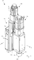
- FIG. 10 An embodiment of a finishing device is in figure 1 shown and denoted overall by the reference numeral 10 there.
- the finishing device 10 comprises a machine tool unit 12 with a base 14 and a carrier 16 movably mounted on the base 14.
- the base 14 is held on a device carrier, not shown.
- the base 14 is held on the equipment carrier so that it can be displaced along an x-axis. If the z-axis shown in the drawing corresponds to a vertical direction, the base 14 forms a horizontal slide.
- the carrier 16 serves as a holder for a drive 18 for linearly driving a slide 20 in a direction parallel to the z-axis, for example by means of a spindle drive 22.
- the slide 20 can also be referred to as a vertical slide.
- the carriage 20 is used to hold a tool 24, which is designed in particular in the form of a cup wheel 26 and has an annular effective surface 28 for the finishing machining of a workpiece (not shown).
- the tool 24 can be driven in the direction of rotation by means of a rotary drive 30 .
- the rotary drive 30 is also connected to the carriage 20 .
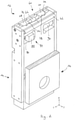
- the base 14 and the carrier 16 are each essentially flat elements which extend within extension planes that are essentially parallel to one another (here: in the x, z plane).
- a storage unit 32 is provided for storing the carrier 16 on the base 14 .
- the bearing unit 32 is designed in the form of a pendulum or pivot bearing. This comprises a bearing part 34 connected to the base 16 with an outer ring 36 for supporting an inner ring 38 which is non-rotatably connected to a carrier 14 associated bearing part 40 is connected.
- the outer ring 36 and the inner ring 38 together form a spherical bearing, which makes it possible to move the carrier-fixed bearing part 40 and thus the carrier 14 about a number of rotational axes.
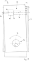
- the carrier can be moved about an inclination axis 42, which corresponds to the x-axis (cf Figures 4 to 6 ).
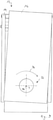
- the bearing part 40 and thus the carrier 14 can be pivoted about a pivot axis 44, which corresponds to the y-axis (cf Figures 7 to 9 ).
- the machine tool unit 12 preferably comprises a plurality of pressure devices 46 and pull devices 48.
- the devices 46 and 48 preferably each extend perpendicularly to the extension planes of the base 14 and the carrier 16.
- the pressure devices 46 are designed, for example, in the form of compression springs and are fixed, for example, to the base 14, preferably by means of a screw 50.
- the free end of the compression spring exerts a compressive force on an underside 54 of the carrier 16 with an end face 52 .
- the bottom 54 of the carrier 16 faces a top 56 of the base 14 .
- a plurality of pressure devices 52 are preferably distributed around the bearing unit 32 along a circumference. Spatially offset from the pressure devices 46 and spatially offset from the storage unit 32, a plurality of pulling devices 48 are preferably arranged. Along one of the axes, for example along the z-axis, the pressure devices 46 and the tension devices 48 are arranged on opposite sides in relation to a center point of the storage unit 32 .
- the pulling devices 48 include, for example, a pull rod 58 which is connected to the carrier 16 and is subjected to train by means of a compression spring 60 .
- the pressure devices 46 and the traction devices 48 generate an effective torque around the bearing unit 32, which prestresses the carrier 16 in the direction of rotation about the x-axis.
- This bias counteracts an inclination adjustment device 60 described below.
- the inclination adjustment device 60 is arranged on the base 14 and comprises a spindle 66 which can be actuated manually or by a motor and which drives two spindle blocks 68 and 70 in opposite directions.
- the spindle 66 has a left-hand thread that interacts with the spindle block 68 and a right-hand thread that interacts with the spindle block 70 .
- the spindle blocks 68 and 70 interact with respective mating surfaces 76 and 78 via inclined surfaces 72 and 74, which are firmly connected to the pressing body 62.
- the spindle 66 can be driven in such a way that the distance between the spindle blocks 68 and 70 increases.
- the pressing body 62 always exerts a compressive force on the carrier 16 , so that the inclination adjustment device 60 is also effective as a pressure device 46 .
- the machine tool unit 12 comprises a pivoting position adjustment device 84 (cf figure 8 ).
- This includes a drive part 86, for example in the form of a manually or motor-operated pin 86, which is connected to the base 14 and, with a preferably hardened and rounded pressure surface 87, acts on a driven part 88, which is fixedly connected to the carrier 16.
- the driven part 88 is clamped between the drive part 86 and a counter-holder 90 connected to the base 14 .
- the counter-holder 90 also includes a preferably hardened and rounded pressing surface 92.
- the counter-holder 90 is designed, for example, in the form of a cylinder/piston unit and/or in the form of a compression spring, in particular with a square cross section.
- the counter-holder 90 causes the drive part 86 and the position of the driven part 88 to be firmly clamped between the pressing surface 87 and the pressing surface 92 in all pivoted positions of the carrier 16, regardless of the setting.
- the swivel position adjustment device 84 makes it possible to move the carrier 16 from an in figure 7 illustrated basic position in a first pivoting direction 94 (cf figure 8 ) and in a second pivoting direction 96 opposite thereto (cf figure 9 ).
- the inclination adjustment device 60 and the swivel position adjustment device 84 are arranged in spatial proximity to one another in the region of an end of the base 14 which is remote from the bearing unit 32 . This enables a particularly precise adjustment of the inclination and pivoting position of the carrier 16.
Landscapes
- Engineering & Computer Science (AREA)
- Mechanical Engineering (AREA)
- Machine Tool Units (AREA)
Description
- Die Erfindung betrifft eine Werkzeugmaschineneinheit zur Ausrichtung eines Werkzeugs oder eines Werkstücks, mit einer Basis zur Verbindung mit einem Maschinengestell und mit einem relativ zu der Basis bewegbaren Träger zur Anordnung des Werkzeugs oder des Werkstücks.
- Werkzeugmaschineneinheiten sind aus der
DE 42 07 201 A1 , derGB 872 847 A US 2 774 642 A vorbekannt, wobei dieDE 42 07 201 A1 die Basis für den Oberbegriff des Anspruchs 1 darstellt. - Der vorliegenden Erfindung liegt die Aufgabe zugrunde, eine Werkzeugmaschineneinheit zu schaffen, welche kompakt ist und eine einfache Einstellung einer Raumlage eines an dem Träger angeordneten Werkzeugs oder Werkstücks ermöglicht.
- Diese Aufgabe wird durch eine Werkzeugmaschineneinheit nach Anspruch 1 gelöst.
- Die erfindungsgemäßen Werkzeugmaschineneinheit ermöglicht es, den Träger unmittelbar an der Basis zu lagern, wobei die Lagereinheit drei Rotationsfreiheitsgrade bereitstellt, sodass der Träger um drei zueinander senkrechte Achsen herum bewegbar ist. Auf diese Weise ist es nicht erforderlich, zwischen Basis und Träger ein Zwischenelement anzuordnen, welches mit einem Rotationsfreiheitsgrad beweglich an der Basis angeordnet ist und welches mit einem weiteren Rotationsfreiheitsgrad eine bewegliche Lagerung für den Träger schafft.
- Die Lagereinheit ist in Form eines Pendel- oder Gelenklagers ausgebildet. Dieses Lager hat drei Rotationsfreiheitsgrade.
- Das Pendel- oder Gelenklager ermöglicht eine Bewegung des Trägers um einen virtuellen Lagerpunkt herum um drei zueinander senkrechte Rotationsachsen. Die Rotationsfreiheitsgrade sind durch sphärische Gleitflächen realisiert.
- Erfindungsgemäß ist zudem vorgesehen, dass eine Schwenklageneinstelleinrichtung zur Einstellung einer Schwenklage des Trägers um eine Schwenkachse vorgesehen ist. Dies ist insbesondere dann vorteilhaft, wenn der Träger zur Anordnung eines Finishwerkzeugs, insbesondere in Form einer Topfscheibe, dient. In diesem Fall kann durch Einstellung der Schwenklage des Trägers ein Krümmungsprofil einer zu bearbeiteten Werkstückoberfläche beeinflusst werden, sodass dieses wahlweise eben, konkav gekrümmt (hohl) oder konvex gekrümmt (ballig) ist.
- Ein Verstellbereich der Schwenklageneinstelleinrichtung kann beispielsweise bezogen auf eine Mittellage +/- 5°, insbesondere +/- 2° betragen.
- Die Schwenkachse erstreckt sich erfindungsgemäß senkrecht zu einer Erstreckungsebene des Trägers und senkrecht zu einer Neigungsachse.
- Erfindungsgemäß ist der Träger um die Schwenkachse verschwenkbar und um die Neigungsachse neigungseinstellbar, wobei die Schwenkachse und die Neigungsachse zueinander senkrecht verlaufen und wobei der Träger um eine sowohl zu der Schwenkachse als auch zu der Neigungsachse senkrechte dritte Achse herum unbewegbar ist. Auf diese Weise kann mit wenigen Bauteilen eine besonders stabile Lagerung des Trägers an der Basis geschaffen werden.
- Eine besonders vorteilhafte Ausführungsform der Erfindung sieht vor, dass zur Festlegung des Trägers an der Basis mindestens eine Druckeinrichtung vorgesehen ist, welche den Träger von der Basis wegdrückt, und/oder mindestens eine Zugeinrichtung, welche den Träger in Richtung auf die Basis zieht. Die Druckeinrichtung und die Zugeinrichtung ermöglichen es, den Träger relativ zu der Basis zu verspannen, sodass unabhängig von der Raumlage, die der Träger relativ zu der Basis einnimmt, der Träger spielfrei an der Basis gehalten ist. Insbesondere kann auch ein etwaig vorhandenes Spiel der Lagereinheit ausgeglichen werden.
- Eine besonders stabile Lagerung des Trägers an der Basis ergibt sich, wenn die Druckeinrichtung die Zugeinrichtung räumlich voneinander versetzt angeordnet sind. Dies bedeutet, dass die Druckeinrichtung und die Zugeinrichtung nicht entlang zueinander koaxialer Achsen eine Druckkraft beziehungsweise Zugkraft auf den Träger ausüben, sondern entlang von zueinander versetzten, insbesondere zueinander parallelen Achsen.
- Eine vereinfachte Ausrichtung des Trägers relativ zu der Basis ergibt sich, wenn eine Neigungseinstelleinrichtung zur Einstellung einer Neigung des Trägers um eine Neigungsachse vorgesehen ist.
- Ein Verstellbereich der Neigungseinstelleinrichtung kann beispielsweise bezogen auf eine Mittellage +/- 2°, insbesondere +/- 0,5° betragen.
- Vorzugsweise erstreckt sich die Neigungsachse parallel zu einer Erstreckungsebene des Trägers. Dies ist insbesondere dann bevorzugt, wenn es sich bei dem an dem Träger angeordneten Werkzeug um ein Finishwerkzeug, insbesondere in Form einer Topfscheibe, handelt, welche eine zu bearbeitende Oberfläche eines Werkstücks mit einer Kreuzschliffstruktur versieht. Der Winkel von einander kreuzenden Schleifspuren kann dann mittels der Neigungseinstelleinrichtung beeinflusst werden.
- Besonders bevorzugt ist es, wenn die Neigungseinstelleinrichtung als Druckeinrichtung wirksam ist, welche den Träger von der Basis wegdrückt. Auf diese Weise kann auf zumindest eine der Druckeinrichtungen verzichtet werden.
- Besonders bevorzugt ist es, wenn die Neigungseinstelleinrichtung einen prismenförmigen Andrückkörper umfasst, welcher mit einem Teilumfang seiner Mantelfläche an einer Kontaktfläche des Trägers oder der Basis anliegt. Bei einem solchen Andrückkörper kann es sich beispielsweise um einen zylindrischen Körper handeln, der mit einer Mantellinie mit einer Kontaktfläche des Trägers oder der Basis zusammenwirkt. Der im Vergleich zu einer Punktabstützung linienförmige Kontakt ermöglicht es, den Träger hinsichtlich eines Rotationsfreiheitsgrads relativ zu der Basis festzulegen. Es ist also möglich, dass die Lagereinheit selbst drei Rotationsfreiheitsgrade bereitstellt, von denen aber nur zwei Rotationsfreiheitsgrade genutzt werden, wobei ein dritter Rotationsfreiheitsgrad durch den linienförmigen Kontakt zwischen dem Andrückkörper und dem Träger oder der Basis gesperrt wird.
- Es versteht sich, dass die Basis nicht unmittelbar mit einem ortsfesten Maschinenfundament des Maschinengestells verbunden sein muss, sondern auch an einem Teil des Maschinengestells gelagert sein kann, welcher seinerseits relativ zu einem Aufstellort bewegbar ist.
- In entsprechender Weise ist es nicht erforderlich, ein Werkzeug oder ein Werkstück unmittelbar und unbewegbar mit dem Träger zu verbinden; der Träger kann vielmehr auch zur Anordnung weiterer Elemente (Schlitten- oder Kreuzschlittenanordnungen, Dreh- und/oder Linearantrieb für ein Werkzeug oder Werkstück) dienen.
- Wie vorstehend beschrieben, ergeben sich besondere Vorteile bei der Verwendung der Werkzeugmaschineneinheit als Teil einer Finishvorrichtung, da die erfindungsgemäße Werkzeugmaschineneinheit eine besonders präzise und gleichzeitig stabile Lagerung eines Werkzeugs oder eines Werkstücks ermöglicht.
- Weitere Merkmale und Vorteile der Erfindung sind Gegenstand der nachfolgenden Beschreibung und der zeichnerischen Darstellung eines bevorzugten Ausführungsbeispiels.
- In der Zeichnung zeigen
- Fig. 1
- eine perspektivische Darstellung einer Finishvorrichtung;
- Fig. 2
- eine perspektivische Darstellung einer Werkzeugmaschineneinheit der Finishvorrichtung gemäß
Fig. 1 ; - Fig. 3
- eine perspektivische Darstellung der Werkzeugmaschineneinheit gemäß
Fig. 2 aus einer rückwärtigen Perspektive; - Fig. 4
- eine Seitenansicht der Werkzeugmaschineneinheit gemäß
Fig. 2 , wobei ein Träger der Werkzeugmaschineneinheit eine Neigungsgrundstellung einnimmt; - Fig. 5
- eine der
Fig. 4 entsprechende Ansicht, mit einem ausgehend aus der Neigungsgrundstellung in einer ersten Richtung geneigten Träger; - Fig. 6
- eine der
Fig. 4 entsprechende Ansicht, mit einem ausgehend aus der Neigungsgrundstellung in einer zweiten Richtung geneigten Träger; - Fig. 7
- eine Draufsicht der Werkzeugmaschineneinheit gemäß
Fig. 2 , wobei der Träger eine Schwenklagengrundstellung einnimmt; - Fig. 8
- eine der
Fig. 7 entsprechende Ansicht, mit einem ausgehend aus der Schwenklagengrundstellung in einer ersten Richtung verschwenkten Träger; und - Fig. 9
- eine der
Fig. 7 entsprechende Ansicht, mit einem ausgehend aus der Schwenklagengrundstellung in einer zweiten Richtung verschwenkten Träger. - Eine Ausführungsform einer Finishvorrichtung ist in
Figur 1 dargestellt und dort insgesamt mit dem Bezugszeichen 10 bezeichnet. Die Finishvorrichtung 10 umfasst eine Werkzeugmaschineneinheit 12 mit einer Basis 14 und einem an der Basis 14 bewegbar gelagerten Träger 16. Die Basis 14 ist an einem nicht dargestellten Geräteträger gehalten. Insbesondere ist die Basis 14 längs einer x-Achse verschiebbar an dem Geräteträger gehalten. Für den Fall, dass die in der Zeichnung dargestellte z-Achse einer vertikalen Richtung entspricht, bildet die Basis 14 einen Horizontalschlitten. - Der Träger 16 dient bei dem der in der Zeichnung dargestellten Ausführungsbeispiel als Halter für einen Antrieb 18 zum Linearantrieb eines Schlittens 20 in zu der z-Achse paralleler Richtung, beispielsweise mittels eines Spindeltriebs 22. Der Schlitten 20 kann auch als Vertikalschlitten bezeichnet werden.
- Der Schlitten 20 dient zur Aufnahme eines Werkzeugs 24, welches insbesondere in Form einer Topfscheibe 26 ausgebildet ist und eine ringförmige Wirkfläche 28 zur finishenden Bearbeitung eines (nicht dargestellten) Werkstücks aufweist. Das Werkzeug 24 ist mittels eines Drehantriebs 30 in Drehrichtung antreibbar. Der Drehantrieb 30 ist ebenfalls mit dem Schlitten 20 verbunden.
- Nachfolgend werden der Aufbau und die Funktionsweise der Werkzeugmaschineneinheit 12 unter Bezugnahme auf die
Figuren 2 bis 9 beschrieben. - Die Basis 14 und der Träger 16 sind jeweils im Wesentlichen flächige Elemente, welche sich innerhalb zueinander im Wesentlichen paralleler Erstreckungsebenen erstrecken (hier: in der x-, z-Ebene). Zur Lagerung des Trägers 16 an der Basis 14 ist eine Lagereinheit 32 vorgesehen. Diese ist in
Figur 3 perspektivisch und in denFiguren 4 bis 6 in einem Schnitt dargestellt. Beim dargestellten Ausführungsbeispiel ist die Lagereinheit 32 in Form eines Pendel- oder Gelenklagers ausgebildet. Dieses umfasst ein mit der Basis 16 verbundenes Lagerteil 34 mit einem Außenring 36 zur Lagerung eines Innenrings 38, der drehfest mit einem mit dem Träger 14 verbundenen Lagerteil 40 verbunden ist. Der Außenring 36 und der Innenring 38 bilden gemeinsam ein sphärisches Lager, welches ermöglicht, den trägerfesten Lagerteil 40 und somit den Träger 14 um mehrere Rotationsachsen bewegen zu können. Insbesondere kann der Träger um eine Neigungsachse 42, welche der x-Achse entspricht, bewegt werden (vergleicheFiguren 4 bis 6 ). Ferner kann das Lagerteil 40 und somit der Träger 14 um eine Schwenkachse 44, welche der y-Achse entspricht, verschwenkt werden (vergleicheFiguren 7 bis 9 ). - Zur Festlegung des Trägers 16 an der Basis 14 und Fixierung in einer bestimmten Neigungs- und Schwenklage umfasst die Werkzeugmaschineneinheit 12 vorzugsweise jeweils mehrere Druckeinrichtungen 46 und Zugeinrichtungen 48.
- Die Einrichtungen 46 und 48 erstrecken sich vorzugsweise jeweils senkrecht zu den Erstreckungsebenen der Basis 14 und des Trägers 16. Die Druckeinrichtungen 46 sind beispielsweise in Form von Druckfedern ausgebildet und beispielsweise an der Basis 14 fixiert, vorzugsweise mittels einer Schraube 50. Das freie Ende der Druckfeder übt mit einer Stirnfläche 52 eine Druckkraft auf eine Unterseite 54 des Trägers 16 aus. Die Unterseite 54 des Trägers 16 ist einer Oberseite 56 der Basis 14 zugewandt.
- Vorzugsweise sind mehrere Druckeinrichtungen 52 entlang eines Umfangs um die Lagereinheit 32 verteilt angeordnet. Räumlich versetzt zu den Druckeinrichtungen 46 und räumlich versetzt zu der Lagereinheit 32 sind vorzugsweise mehrere Zugeinrichtungen 48 angeordnet. Entlang einer der Achsen, beispielsweise entlang der z-Achse, sind die Druckeinrichtungen 46 und die Zugeinrichtungen 48 bezogen auf einen Mittelpunkt der Lagereinheit 32 auf einander gegenüberliegenden Seiten angeordnet.
- Die Zugeinrichtungen 48 umfassen beispielsweise eine Zugstange 58, welche mit dem Träger 16 verbunden ist und mittels einer Druckfeder 60 auf Zug beansprucht ist.
- Die Druckeinrichtungen 46 und die Zugeinrichtungen 48 erzeugen ein um die Lagereinheit 32 wirksames Drehmoment, welches den Träger 16 in Drehrichtung um die x-Achse vorspannt. Dieser Vorspannung wirkt eine nachfolgend beschriebene Neigungseinstelleinrichtung 60 entgegen. Diese umfasst einen zylindrischen Andrückkörper 62, welcher sich vorzugsweise parallel zu der x-Achse erstreckt und mit einer linienförmige Kontaktfläche 64 mit der Unterseite 54 des Trägers 16 zusammenwirkt (vergleiche
Figur 4 ). - Die Neigungseinstelleinrichtung 60 ist an der Basis 14 angeordnet und umfasst eine Spindel 66, welche von Hand oder motorisch betätigbar ist und zwei Spindelblöcke 68 und 70 gegenläufig antreibt. Hierfür weist die Spindel 66 ein mit dem Spindelblock 68 zusammenwirkendes Linksgewinde und ein mit dem Spindelblock 70 zusammenwirkendes Rechtsgewinde auf. Die Spindelblöcke 68 und 70 wirken über Schrägflächen 72 beziehungsweise 74 mit jeweiligen Gegenflächen 76 und 78 zusammen, welche fest mit dem Andrückkörper 62 verbunden sind. Ausgehend aus einer in den
Figuren 2 und4 dargestellten Neigungsgrundstellung kann die Spindel 66 so angetrieben werden, dass sich der Abstand zwischen den Spindelblöcken 68 und 70 vergrößert. Dies bewirkt eine Aushubbewegung des Andrücckörpers 62 aus der Basis 14 heraus, sodass der Träger 16 in einer ersten Richtung 80 um die Neigungsachse 42 verschwenkt wird. In entsprechender Weise kann der Träger 16 durch Verringerung der Distanz der Spindelblöcke 68 und 70 in einer zu der ersten Richtung 80 entgegengesetzten zweiten Richtung 82 um die Neigungsachse 42 bewegt werden (vergleicheFigur 6 ). - Unabhängig von der Neigungslage des Trägers 16 um die Neigungsachse 42 übt der Andrückkörper 62 immer eine Druckkraft auf den Träger 16 aus, sodass die Neigungseinstelleinrichtung 60 auch als Druckeinrichtung 46 wirksam ist.
- Da sich die Kontaktfläche 64 des Andrückkörpers 62 parallel zu der x-Achse erstreckt, wird eine Bewegung des Trägers 16 um die z-Achse verhindert. Dieser dritte Rotationsfreiheitsgrad wird also prinzipiell durch die Lagereinheit 32 vorgehalten, jedoch nicht genutzt.
- Zur Einstellung einer Schwenklage des Trägers 16 um eine Schwenkachse 44, welche der y-Achse entspricht, umfasst die Werkzeugmaschineneinheit 12 eine Schwenklageneinstelleinrichtung 84 (vergleiche
Figur 8 ). Diese umfasst ein Antriebsteil 86, beispielsweise in Form eines manuell oder motorisch betätigbaren Stifts 86, welcher mit der Basis 14 verbunden ist und mit einer vorzugsweise gehärteten und abgerundeten Andrückfläche 87 auf ein Abtriebsteil 88 wirkt, welches fest mit dem Träger 16 verbunden ist. Das Abtriebsteil 88 ist zwischen dem Antriebsteil 86 und einem mit der Basis 14 verbundenen Gegenhalter 90 eingespannt. Der Gegenhalter 90 umfasst ebenfalls eine vorzugsweise gehärtete und gerundete Andrückfläche 92. Der Gegenhalter 90 ist beispielsweise in Form einer Zylinder-/Kolbeneinheit ausgebildet und/oder in Form einer Druckfeder, insbesondere mit quadratischem Querschnitt. Der Gegenhalter 90 bewirkt, dass unabhängig von der Einstellung des Antriebsteils 86 und der Lage des Abtriebsteils 88 dieses in allen Schwenklagen des Trägers 16 fest zwischen der Andrückfläche 87 und der Andrückfläche 92 eingespannt ist. - Die Schwenklageneinstelleinrichtung 84 ermöglicht es, den Träger 16 aus einer in
Figur 7 dargestellten Grundstellung in einer ersten Schwenkrichtung 94 zu verschwenken (vergleicheFigur 8 ) und in einer hierzu entgegengesetzten zweiten Schwenkrichtung 96 (vergleicheFigur 9 ). - Die Neigungseinstelleinrichtung 60 und die Schwenklageneinstelleinrichtung 84 sind in räumlicher Nähe zueinander im Bereich eines von der Lagereinheit 32 entfernten Endes der Basis 14 angeordnet. Dies ermöglicht eine besonders präzise Einstellung der Neigung und Schwenklage des Trägers 16.
Claims (7)
- Werkzeugmaschineneinheit (12) zur Ausrichtung eines Werkzeugs (24) oder eines Werkstücks, mit einer Basis (14) zur Verbindung mit einem Maschinengestell und mit einem relativ zu der Basis (14) bewegbaren Träger (16) zur Anordnung des Werkzeugs oder des Werkstücks (24), wobei zur Lagerung des Trägers (16) an der Basis (14) eine Lagereinheit (32) mit mindestens zwei Rotationsfreiheitsgraden vorgesehen ist, wobei eine Schwenklageneinstelleinrichtung (84) zur Einstellung einer Schwenklage des Trägers (16) um eine Schwenkachse (44) vorgesehen ist und der Träger (16) um eine Neigungsachse (42) neigungseinstellbar ist, wobei die Schwenkachse (44) und die Neigungsachse (42) zueinander senkrecht verlaufen, und wobei der Träger (16) um eine sowohl zu der Schwenkachse (44) als auch zu der Neigungsachse (42) senkrechte dritte Achse herum unbewegbar ist, dadurch gekennzeichnet, dass sich die Schwenkachse (44) senkrecht zu einer Erstreckungsebene des Trägers (16) erstreckt und dass die Lagereinheit (32) in Form eines Pendel- oder Gelenklagers ausgebildet ist, das drei Rotationsfreiheitsgrade aufweist, die durch sphärische Gleitflächen realisiert sind.
- Werkzeugmaschineneinheit (12) nach Anspruch 1, dadurch gekennzeichnet, dass zur Festlegung des Trägers (16) an der Basis (14) mindestens eine Druckeinrichtung (46) vorgesehen ist, welche den Träger (16) von der Basis (14) wegdrückt, und/oder mindestens eine Zugeinrichtung (48), welche den Träger (16) in Richtung auf die Basis (14) zieht.
- Werkzeugmaschineneinheit (12) nach Anspruch 2, dadurch gekennzeichnet, dass die Druckeinrichtung (46) und die Zugeinrichtung (48) räumlich voneinander versetzt angeordnet sind.
- Werkzeugmaschineneinheit (12) nach einem der voranstehenden Ansprüche, dadurch gekennzeichnet, dass eine Neigungseinstelleinrichtung (60) zur Einstellung einer Neigung des Trägers (16) um eine Neigungsachse (42) vorgesehen ist.
- Werkzeugmaschineneinheit nach Anspruch 4, dadurch gekennzeichnet, dass sich die Neigungsachse (42) parallel zu einer Erstreckungsebene des Trägers (16) erstreckt.
- Werkzeugmaschineneinheit (12) nach Anspruch 4 oder 5, dadurch gekennzeichnet, dass die Neigungseinstelleinrichtung (60) als Druckeinrichtung (46) wirksam ist, welche den Träger (16) von der Basis (14) wegdrückt.
- Werkzeugmaschineneinheit (12) nach einem der Ansprüche 4 bis 6, dadurch gekennzeichnet, dass die Neigungseinstelleinrichtung (60) einen prismenförmigen Andrückkörper (62) umfasst, welcher mit einem Teilumfang seiner Mantelfläche an einer Kontaktfläche (54) des Trägers (16) oder der Basis (14) anliegt.
Applications Claiming Priority (1)
| Application Number | Priority Date | Filing Date | Title |
|---|---|---|---|
| DE102014223101.9A DE102014223101A1 (de) | 2014-11-12 | 2014-11-12 | Werkzeugmaschineneinheit zur Ausrichtung eines Werkzeugs oder eines Werkstücks |
Publications (3)
| Publication Number | Publication Date |
|---|---|
| EP3020506A1 EP3020506A1 (de) | 2016-05-18 |
| EP3020506B1 EP3020506B1 (de) | 2018-11-14 |
| EP3020506B2 true EP3020506B2 (de) | 2022-03-02 |
Family
ID=54199544
Family Applications (1)
| Application Number | Title | Priority Date | Filing Date |
|---|---|---|---|
| EP15186301.6A Active EP3020506B2 (de) | 2014-11-12 | 2015-09-22 | Werkzeugmaschineneinheit zur ausrichtung eines werkzeugs oder eines werkstücks |
Country Status (2)
| Country | Link |
|---|---|
| EP (1) | EP3020506B2 (de) |
| DE (1) | DE102014223101A1 (de) |
Families Citing this family (1)
| Publication number | Priority date | Publication date | Assignee | Title |
|---|---|---|---|---|
| DE102019214867B4 (de) * | 2019-09-27 | 2021-10-28 | Kadia Produktion Gmbh + Co. | Honmaschine |
Citations (1)
| Publication number | Priority date | Publication date | Assignee | Title |
|---|---|---|---|---|
| EP1920877B1 (de) † | 2006-11-10 | 2010-02-24 | Thielenhaus Technologies GmbH | Schwenkbare Werkzeugschlittenanordnung |
Family Cites Families (9)
| Publication number | Priority date | Publication date | Assignee | Title |
|---|---|---|---|---|
| US2774642A (en) * | 1955-03-21 | 1956-12-18 | Cincinnati Milling Machine Co | Adjustable table for milling machines |
| GB872847A (en) * | 1957-12-05 | 1961-07-12 | Coventry Gauge & Tool Co Ltd | Compound angle work table |
| JPH0830743B2 (ja) | 1991-03-07 | 1996-03-27 | 株式会社ミツトヨ | レベリング装置 |
| DE4401496C3 (de) * | 1994-01-20 | 2001-07-26 | Emag Maschfab Gmbh | Werkzeugschneiden-Verstelleinrichtung zum Bearbeiten von runden, unrunden und/oder nicht zylinderförmigen Innen- und/oder Außenkonturen |
| JP3234872B2 (ja) * | 1996-10-08 | 2001-12-04 | セイコーインスツルメンツ株式会社 | アクチュエータおよびその駆動方法、および、その駆動方法をコンピュータに実行させるためのプログラムを記録したコンピュータ読み取り可能な記録媒体、並びに、そのアクチュエータを用いた小型工作機械 |
| DE19859360C2 (de) * | 1998-12-22 | 2003-07-17 | Schwaebische Werkzeugmaschinen | Werkzeugmaschine mit piezoelektrischer Positionskorrektureinrichtung |
| DE102006004747A1 (de) * | 2006-02-02 | 2007-08-09 | Supfina Grieshaber Gmbh & Co.Kg | Vorrichtung zum Einstellen einer Werkzeugspindel |
| EP2305418A1 (de) * | 2009-10-03 | 2011-04-06 | Fischer AG Präzisionsspindeln | Mehrachsen-Schwenkkopf-Anordnung für eine Bearbeitungsmaschine |
| DE202010008979U1 (de) * | 2010-11-08 | 2012-02-09 | Starrag Heckert Ag | Einrichtung zur Lagekorrektur von Elementen einer Werkzeugmaschine und Kompensationselement dafür |
-
2014
- 2014-11-12 DE DE102014223101.9A patent/DE102014223101A1/de not_active Withdrawn
-
2015
- 2015-09-22 EP EP15186301.6A patent/EP3020506B2/de active Active
Patent Citations (1)
| Publication number | Priority date | Publication date | Assignee | Title |
|---|---|---|---|---|
| EP1920877B1 (de) † | 2006-11-10 | 2010-02-24 | Thielenhaus Technologies GmbH | Schwenkbare Werkzeugschlittenanordnung |
Also Published As
| Publication number | Publication date |
|---|---|
| EP3020506B1 (de) | 2018-11-14 |
| EP3020506A1 (de) | 2016-05-18 |
| DE102014223101A1 (de) | 2016-05-12 |
Similar Documents
| Publication | Publication Date | Title |
|---|---|---|
| DE19641831B4 (de) | Universal-Fräs- und Bohrmaschine | |
| DE202017100994U1 (de) | Querträgerschrauben-Stützeinrichtung für Bearbeitungsmaschinen in Portalform | |
| DE202007001985U1 (de) | Spannvorrichtung | |
| DE102013225292B4 (de) | Schleifmaschine zum schleifen von zentrischen und/oder exzentrischen lagerstellen an wellenteilen mit einer lünette zum abstützen der lagerstellen | |
| EP3765670B1 (de) | Schienen-schleifmaschine zum schleifen von schienen eines gleises | |
| EP1815939B1 (de) | Halterung für eine Spanneinheit mit über Führungsnuten und Nutensteine verschiebbaren Stellplatten und Konsole ; Spannvorrichtung mit einer solchen Halterung | |
| EP3020506B2 (de) | Werkzeugmaschineneinheit zur ausrichtung eines werkzeugs oder eines werkstücks | |
| EP0014768A1 (de) | Vorrichtung zum Handhaben eines an einem Ausleger schwenk- und drehbar angeordneten Werkzeuges | |
| DE102015104058B3 (de) | Zentrische Spannvorrichtung | |
| EP3072635B1 (de) | Vorrichtung zum abstützen eines zu bearbeitenden werkstücks | |
| WO2010097366A9 (de) | Schlittensystem für werkzeugmaschinen | |
| DE102017107571B3 (de) | Spanneinheit mit verschwenkbarem Spannmodul und Spannsystem | |
| EP3251788B1 (de) | Vorrichtung zum abstützen eines zu bearbeitenden werkstücks | |
| EP3856113B1 (de) | Tischsäule für einen operationstisch mit versteifungsmechanismus für eine zylindrische führung | |
| EP2881218B1 (de) | Lünette zur Abstützung eines Werkstücks | |
| EP2371482A1 (de) | Werkzeugmaschine | |
| EP3524386B1 (de) | Vorrichtung zum abstützen eines zu bearbeitenden werkstücks | |
| DE102010038818B4 (de) | Werkzeugvorrichtung und Werkzeugmaschine | |
| EP2803445B1 (de) | Vorrichtung zur bandfinishenden Bearbeitung eines Werkstücks | |
| DE102004025061B4 (de) | Werkzeugantrieb, insbesondere zum automatischen Entgraten, Kantenbrechen oder Verputzen von Werkstücken | |
| DE1294272B (de) | Mechanische Nachfuehrvorrichtung | |
| DE102008045975A1 (de) | Spannvorrichtung | |
| DE1905144B2 (de) | Abrichtvorrichtung fuer schleifscheiben zum abrichten von konkaven und konvexen profilen mit geradliniger anschlussbewegung | |
| EP3394651B1 (de) | Ausrichtungsvorrichtung für ein ende einer lichtleitfaser | |
| DE3915532C2 (de) |
Legal Events
| Date | Code | Title | Description |
|---|---|---|---|
| PUAI | Public reference made under article 153(3) epc to a published international application that has entered the european phase |
Free format text: ORIGINAL CODE: 0009012 |
|
| AK | Designated contracting states |
Kind code of ref document: A1 Designated state(s): AL AT BE BG CH CY CZ DE DK EE ES FI FR GB GR HR HU IE IS IT LI LT LU LV MC MK MT NL NO PL PT RO RS SE SI SK SM TR |
|
| AX | Request for extension of the european patent |
Extension state: BA ME |
|
| 17P | Request for examination filed |
Effective date: 20160916 |
|
| RBV | Designated contracting states (corrected) |
Designated state(s): AL AT BE BG CH CY CZ DE DK EE ES FI FR GB GR HR HU IE IS IT LI LT LU LV MC MK MT NL NO PL PT RO RS SE SI SK SM TR |
|
| RIN1 | Information on inventor provided before grant (corrected) |
Inventor name: SONNTAG, DANIEL Inventor name: KOENIG, RAPHAEL Inventor name: MUELLER, MARKUS |
|
| RIN1 | Information on inventor provided before grant (corrected) |
Inventor name: MUELLER, MARKUS Inventor name: KOENIG, RAPHAEL Inventor name: SONNTAG, DANIEL |
|
| GRAP | Despatch of communication of intention to grant a patent |
Free format text: ORIGINAL CODE: EPIDOSNIGR1 |
|
| STAA | Information on the status of an ep patent application or granted ep patent |
Free format text: STATUS: GRANT OF PATENT IS INTENDED |
|
| INTG | Intention to grant announced |
Effective date: 20180524 |
|
| GRAS | Grant fee paid |
Free format text: ORIGINAL CODE: EPIDOSNIGR3 |
|
| GRAA | (expected) grant |
Free format text: ORIGINAL CODE: 0009210 |
|
| STAA | Information on the status of an ep patent application or granted ep patent |
Free format text: STATUS: THE PATENT HAS BEEN GRANTED |
|
| AK | Designated contracting states |
Kind code of ref document: B1 Designated state(s): AL AT BE BG CH CY CZ DE DK EE ES FI FR GB GR HR HU IE IS IT LI LT LU LV MC MK MT NL NO PL PT RO RS SE SI SK SM TR |
|
| REG | Reference to a national code |
Ref country code: CH Ref legal event code: EP Ref country code: AT Ref legal event code: REF Ref document number: 1064241 Country of ref document: AT Kind code of ref document: T Effective date: 20181115 |
|
| REG | Reference to a national code |
Ref country code: DE Ref legal event code: R096 Ref document number: 502015006848 Country of ref document: DE |
|
| REG | Reference to a national code |
Ref country code: IE Ref legal event code: FG4D Free format text: LANGUAGE OF EP DOCUMENT: GERMAN |
|
| REG | Reference to a national code |
Ref country code: NL Ref legal event code: MP Effective date: 20181114 |
|
| REG | Reference to a national code |
Ref country code: LT Ref legal event code: MG4D |
|
| PG25 | Lapsed in a contracting state [announced via postgrant information from national office to epo] |
Ref country code: HR Free format text: LAPSE BECAUSE OF FAILURE TO SUBMIT A TRANSLATION OF THE DESCRIPTION OR TO PAY THE FEE WITHIN THE PRESCRIBED TIME-LIMIT Effective date: 20181114 Ref country code: FI Free format text: LAPSE BECAUSE OF FAILURE TO SUBMIT A TRANSLATION OF THE DESCRIPTION OR TO PAY THE FEE WITHIN THE PRESCRIBED TIME-LIMIT Effective date: 20181114 Ref country code: LV Free format text: LAPSE BECAUSE OF FAILURE TO SUBMIT A TRANSLATION OF THE DESCRIPTION OR TO PAY THE FEE WITHIN THE PRESCRIBED TIME-LIMIT Effective date: 20181114 Ref country code: BG Free format text: LAPSE BECAUSE OF FAILURE TO SUBMIT A TRANSLATION OF THE DESCRIPTION OR TO PAY THE FEE WITHIN THE PRESCRIBED TIME-LIMIT Effective date: 20190214 Ref country code: ES Free format text: LAPSE BECAUSE OF FAILURE TO SUBMIT A TRANSLATION OF THE DESCRIPTION OR TO PAY THE FEE WITHIN THE PRESCRIBED TIME-LIMIT Effective date: 20181114 Ref country code: LT Free format text: LAPSE BECAUSE OF FAILURE TO SUBMIT A TRANSLATION OF THE DESCRIPTION OR TO PAY THE FEE WITHIN THE PRESCRIBED TIME-LIMIT Effective date: 20181114 Ref country code: NO Free format text: LAPSE BECAUSE OF FAILURE TO SUBMIT A TRANSLATION OF THE DESCRIPTION OR TO PAY THE FEE WITHIN THE PRESCRIBED TIME-LIMIT Effective date: 20190214 Ref country code: IS Free format text: LAPSE BECAUSE OF FAILURE TO SUBMIT A TRANSLATION OF THE DESCRIPTION OR TO PAY THE FEE WITHIN THE PRESCRIBED TIME-LIMIT Effective date: 20190314 |
|
| PG25 | Lapsed in a contracting state [announced via postgrant information from national office to epo] |
Ref country code: GR Free format text: LAPSE BECAUSE OF FAILURE TO SUBMIT A TRANSLATION OF THE DESCRIPTION OR TO PAY THE FEE WITHIN THE PRESCRIBED TIME-LIMIT Effective date: 20190215 Ref country code: RS Free format text: LAPSE BECAUSE OF FAILURE TO SUBMIT A TRANSLATION OF THE DESCRIPTION OR TO PAY THE FEE WITHIN THE PRESCRIBED TIME-LIMIT Effective date: 20181114 Ref country code: NL Free format text: LAPSE BECAUSE OF FAILURE TO SUBMIT A TRANSLATION OF THE DESCRIPTION OR TO PAY THE FEE WITHIN THE PRESCRIBED TIME-LIMIT Effective date: 20181114 Ref country code: PT Free format text: LAPSE BECAUSE OF FAILURE TO SUBMIT A TRANSLATION OF THE DESCRIPTION OR TO PAY THE FEE WITHIN THE PRESCRIBED TIME-LIMIT Effective date: 20190314 Ref country code: AL Free format text: LAPSE BECAUSE OF FAILURE TO SUBMIT A TRANSLATION OF THE DESCRIPTION OR TO PAY THE FEE WITHIN THE PRESCRIBED TIME-LIMIT Effective date: 20181114 Ref country code: SE Free format text: LAPSE BECAUSE OF FAILURE TO SUBMIT A TRANSLATION OF THE DESCRIPTION OR TO PAY THE FEE WITHIN THE PRESCRIBED TIME-LIMIT Effective date: 20181114 |
|
| REG | Reference to a national code |
Ref country code: DE Ref legal event code: R026 Ref document number: 502015006848 Country of ref document: DE |
|
| PG25 | Lapsed in a contracting state [announced via postgrant information from national office to epo] |
Ref country code: DK Free format text: LAPSE BECAUSE OF FAILURE TO SUBMIT A TRANSLATION OF THE DESCRIPTION OR TO PAY THE FEE WITHIN THE PRESCRIBED TIME-LIMIT Effective date: 20181114 Ref country code: PL Free format text: LAPSE BECAUSE OF FAILURE TO SUBMIT A TRANSLATION OF THE DESCRIPTION OR TO PAY THE FEE WITHIN THE PRESCRIBED TIME-LIMIT Effective date: 20181114 Ref country code: CZ Free format text: LAPSE BECAUSE OF FAILURE TO SUBMIT A TRANSLATION OF THE DESCRIPTION OR TO PAY THE FEE WITHIN THE PRESCRIBED TIME-LIMIT Effective date: 20181114 Ref country code: IT Free format text: LAPSE BECAUSE OF FAILURE TO SUBMIT A TRANSLATION OF THE DESCRIPTION OR TO PAY THE FEE WITHIN THE PRESCRIBED TIME-LIMIT Effective date: 20181114 |
|
| PLBI | Opposition filed |
Free format text: ORIGINAL CODE: 0009260 |
|
| PLAX | Notice of opposition and request to file observation + time limit sent |
Free format text: ORIGINAL CODE: EPIDOSNOBS2 |
|
| PG25 | Lapsed in a contracting state [announced via postgrant information from national office to epo] |
Ref country code: SK Free format text: LAPSE BECAUSE OF FAILURE TO SUBMIT A TRANSLATION OF THE DESCRIPTION OR TO PAY THE FEE WITHIN THE PRESCRIBED TIME-LIMIT Effective date: 20181114 Ref country code: EE Free format text: LAPSE BECAUSE OF FAILURE TO SUBMIT A TRANSLATION OF THE DESCRIPTION OR TO PAY THE FEE WITHIN THE PRESCRIBED TIME-LIMIT Effective date: 20181114 Ref country code: SM Free format text: LAPSE BECAUSE OF FAILURE TO SUBMIT A TRANSLATION OF THE DESCRIPTION OR TO PAY THE FEE WITHIN THE PRESCRIBED TIME-LIMIT Effective date: 20181114 Ref country code: RO Free format text: LAPSE BECAUSE OF FAILURE TO SUBMIT A TRANSLATION OF THE DESCRIPTION OR TO PAY THE FEE WITHIN THE PRESCRIBED TIME-LIMIT Effective date: 20181114 |
|
| 26 | Opposition filed |
Opponent name: THIELENHAUS TECHNOLOGIES GMBH Effective date: 20190726 |
|
| PG25 | Lapsed in a contracting state [announced via postgrant information from national office to epo] |
Ref country code: SI Free format text: LAPSE BECAUSE OF FAILURE TO SUBMIT A TRANSLATION OF THE DESCRIPTION OR TO PAY THE FEE WITHIN THE PRESCRIBED TIME-LIMIT Effective date: 20181114 |
|
| PLBB | Reply of patent proprietor to notice(s) of opposition received |
Free format text: ORIGINAL CODE: EPIDOSNOBS3 |
|
| PG25 | Lapsed in a contracting state [announced via postgrant information from national office to epo] |
Ref country code: TR Free format text: LAPSE BECAUSE OF FAILURE TO SUBMIT A TRANSLATION OF THE DESCRIPTION OR TO PAY THE FEE WITHIN THE PRESCRIBED TIME-LIMIT Effective date: 20181114 |
|
| PG25 | Lapsed in a contracting state [announced via postgrant information from national office to epo] |
Ref country code: MC Free format text: LAPSE BECAUSE OF FAILURE TO SUBMIT A TRANSLATION OF THE DESCRIPTION OR TO PAY THE FEE WITHIN THE PRESCRIBED TIME-LIMIT Effective date: 20181114 |
|
| REG | Reference to a national code |
Ref country code: CH Ref legal event code: PL |
|
| PG25 | Lapsed in a contracting state [announced via postgrant information from national office to epo] |
Ref country code: CH Free format text: LAPSE BECAUSE OF NON-PAYMENT OF DUE FEES Effective date: 20190930 Ref country code: LI Free format text: LAPSE BECAUSE OF NON-PAYMENT OF DUE FEES Effective date: 20190930 Ref country code: LU Free format text: LAPSE BECAUSE OF NON-PAYMENT OF DUE FEES Effective date: 20190922 Ref country code: IE Free format text: LAPSE BECAUSE OF NON-PAYMENT OF DUE FEES Effective date: 20190922 |
|
| REG | Reference to a national code |
Ref country code: BE Ref legal event code: MM Effective date: 20190930 |
|
| PG25 | Lapsed in a contracting state [announced via postgrant information from national office to epo] |
Ref country code: BE Free format text: LAPSE BECAUSE OF NON-PAYMENT OF DUE FEES Effective date: 20190930 |
|
| GBPC | Gb: european patent ceased through non-payment of renewal fee |
Effective date: 20190922 |
|
| PG25 | Lapsed in a contracting state [announced via postgrant information from national office to epo] |
Ref country code: GB Free format text: LAPSE BECAUSE OF NON-PAYMENT OF DUE FEES Effective date: 20190922 Ref country code: FR Free format text: LAPSE BECAUSE OF NON-PAYMENT OF DUE FEES Effective date: 20190930 |
|
| PG25 | Lapsed in a contracting state [announced via postgrant information from national office to epo] |
Ref country code: CY Free format text: LAPSE BECAUSE OF FAILURE TO SUBMIT A TRANSLATION OF THE DESCRIPTION OR TO PAY THE FEE WITHIN THE PRESCRIBED TIME-LIMIT Effective date: 20181114 |
|
| PG25 | Lapsed in a contracting state [announced via postgrant information from national office to epo] |
Ref country code: MT Free format text: LAPSE BECAUSE OF FAILURE TO SUBMIT A TRANSLATION OF THE DESCRIPTION OR TO PAY THE FEE WITHIN THE PRESCRIBED TIME-LIMIT Effective date: 20181114 Ref country code: HU Free format text: LAPSE BECAUSE OF FAILURE TO SUBMIT A TRANSLATION OF THE DESCRIPTION OR TO PAY THE FEE WITHIN THE PRESCRIBED TIME-LIMIT; INVALID AB INITIO Effective date: 20150922 |
|
| APAH | Appeal reference modified |
Free format text: ORIGINAL CODE: EPIDOSCREFNO |
|
| APBM | Appeal reference recorded |
Free format text: ORIGINAL CODE: EPIDOSNREFNO |
|
| APBP | Date of receipt of notice of appeal recorded |
Free format text: ORIGINAL CODE: EPIDOSNNOA2O |
|
| REG | Reference to a national code |
Ref country code: AT Ref legal event code: MM01 Ref document number: 1064241 Country of ref document: AT Kind code of ref document: T Effective date: 20200922 |
|
| APBU | Appeal procedure closed |
Free format text: ORIGINAL CODE: EPIDOSNNOA9O |
|
| PUAH | Patent maintained in amended form |
Free format text: ORIGINAL CODE: 0009272 |
|
| STAA | Information on the status of an ep patent application or granted ep patent |
Free format text: STATUS: PATENT MAINTAINED AS AMENDED |
|
| PG25 | Lapsed in a contracting state [announced via postgrant information from national office to epo] |
Ref country code: AT Free format text: LAPSE BECAUSE OF NON-PAYMENT OF DUE FEES Effective date: 20200922 |
|
| 27A | Patent maintained in amended form |
Effective date: 20220302 |
|
| AK | Designated contracting states |
Kind code of ref document: B2 Designated state(s): AL AT BE BG CH CY CZ DE DK EE ES FI FR GB GR HR HU IE IS IT LI LT LU LV MC MK MT NL NO PL PT RO RS SE SI SK SM TR |
|
| REG | Reference to a national code |
Ref country code: DE Ref legal event code: R102 Ref document number: 502015006848 Country of ref document: DE |
|
| PG25 | Lapsed in a contracting state [announced via postgrant information from national office to epo] |
Ref country code: MK Free format text: LAPSE BECAUSE OF FAILURE TO SUBMIT A TRANSLATION OF THE DESCRIPTION OR TO PAY THE FEE WITHIN THE PRESCRIBED TIME-LIMIT Effective date: 20181114 |
|
| P01 | Opt-out of the competence of the unified patent court (upc) registered |
Effective date: 20230621 |
|
| PGFP | Annual fee paid to national office [announced via postgrant information from national office to epo] |
Ref country code: DE Payment date: 20250919 Year of fee payment: 11 |