EP3019711B1 - Plated polymer nosecone - Google Patents
Plated polymer nosecone Download PDFInfo
- Publication number
- EP3019711B1 EP3019711B1 EP14832491.6A EP14832491A EP3019711B1 EP 3019711 B1 EP3019711 B1 EP 3019711B1 EP 14832491 A EP14832491 A EP 14832491A EP 3019711 B1 EP3019711 B1 EP 3019711B1
- Authority
- EP
- European Patent Office
- Prior art keywords
- polymeric substrate
- ribs
- nosecone
- height
- plating
- Prior art date
- Legal status (The legal status is an assumption and is not a legal conclusion. Google has not performed a legal analysis and makes no representation as to the accuracy of the status listed.)
- Active
Links
- 229920000642 polymer Polymers 0.000 title description 42
- 239000000758 substrate Substances 0.000 claims description 89
- 238000007747 plating Methods 0.000 claims description 60
- 238000000034 method Methods 0.000 claims description 54
- 230000003014 reinforcing effect Effects 0.000 claims description 16
- 238000004519 manufacturing process Methods 0.000 claims description 14
- 238000001746 injection moulding Methods 0.000 claims description 11
- 238000002347 injection Methods 0.000 claims description 9
- 239000007924 injection Substances 0.000 claims description 9
- 238000000151 deposition Methods 0.000 claims description 4
- 239000012530 fluid Substances 0.000 claims description 4
- 239000000463 material Substances 0.000 description 40
- 229910052751 metal Inorganic materials 0.000 description 40
- 239000002184 metal Substances 0.000 description 40
- 239000002131 composite material Substances 0.000 description 20
- 230000003628 erosive effect Effects 0.000 description 18
- KDLHZDBZIXYQEI-UHFFFAOYSA-N Palladium Chemical compound [Pd] KDLHZDBZIXYQEI-UHFFFAOYSA-N 0.000 description 14
- XEEYBQQBJWHFJM-UHFFFAOYSA-N Iron Chemical compound [Fe] XEEYBQQBJWHFJM-UHFFFAOYSA-N 0.000 description 12
- PXHVJJICTQNCMI-UHFFFAOYSA-N Nickel Chemical compound [Ni] PXHVJJICTQNCMI-UHFFFAOYSA-N 0.000 description 12
- 238000000465 moulding Methods 0.000 description 12
- 229920001187 thermosetting polymer Polymers 0.000 description 12
- 239000004642 Polyimide Substances 0.000 description 11
- 229920001721 polyimide Polymers 0.000 description 11
- 229910045601 alloy Inorganic materials 0.000 description 10
- 239000000956 alloy Substances 0.000 description 10
- 238000000576 coating method Methods 0.000 description 10
- 239000003054 catalyst Substances 0.000 description 9
- 150000002739 metals Chemical class 0.000 description 9
- 238000003466 welding Methods 0.000 description 9
- 238000007772 electroless plating Methods 0.000 description 8
- 238000009713 electroplating Methods 0.000 description 8
- 239000012778 molding material Substances 0.000 description 8
- 229920000728 polyester Polymers 0.000 description 8
- RYGMFSIKBFXOCR-UHFFFAOYSA-N Copper Chemical compound [Cu] RYGMFSIKBFXOCR-UHFFFAOYSA-N 0.000 description 7
- 239000000853 adhesive Substances 0.000 description 7
- 230000001070 adhesive effect Effects 0.000 description 7
- 239000011248 coating agent Substances 0.000 description 7
- 229910052802 copper Inorganic materials 0.000 description 7
- 239000010949 copper Substances 0.000 description 7
- PCHJSUWPFVWCPO-UHFFFAOYSA-N gold Chemical compound [Au] PCHJSUWPFVWCPO-UHFFFAOYSA-N 0.000 description 7
- 229910052737 gold Inorganic materials 0.000 description 7
- 239000010931 gold Substances 0.000 description 7
- 229910052763 palladium Inorganic materials 0.000 description 7
- OKTJSMMVPCPJKN-UHFFFAOYSA-N Carbon Chemical compound [C] OKTJSMMVPCPJKN-UHFFFAOYSA-N 0.000 description 6
- 239000004593 Epoxy Substances 0.000 description 6
- 239000004696 Poly ether ether ketone Substances 0.000 description 6
- 239000004697 Polyetherimide Substances 0.000 description 6
- 230000004913 activation Effects 0.000 description 6
- 229910052799 carbon Inorganic materials 0.000 description 6
- 238000005323 electroforming Methods 0.000 description 6
- 229910052742 iron Inorganic materials 0.000 description 6
- 230000000873 masking effect Effects 0.000 description 6
- 229910052759 nickel Inorganic materials 0.000 description 6
- 229920001652 poly(etherketoneketone) Polymers 0.000 description 6
- 229920002530 polyetherether ketone Polymers 0.000 description 6
- 229920001601 polyetherimide Polymers 0.000 description 6
- 229910052709 silver Inorganic materials 0.000 description 6
- 239000004332 silver Substances 0.000 description 6
- VYZAMTAEIAYCRO-UHFFFAOYSA-N Chromium Chemical compound [Cr] VYZAMTAEIAYCRO-UHFFFAOYSA-N 0.000 description 5
- ATJFFYVFTNAWJD-UHFFFAOYSA-N Tin Chemical compound [Sn] ATJFFYVFTNAWJD-UHFFFAOYSA-N 0.000 description 5
- HCHKCACWOHOZIP-UHFFFAOYSA-N Zinc Chemical compound [Zn] HCHKCACWOHOZIP-UHFFFAOYSA-N 0.000 description 5
- 229920003230 addition polyimide Polymers 0.000 description 5
- 125000001931 aliphatic group Chemical group 0.000 description 5
- 150000008064 anhydrides Chemical class 0.000 description 5
- 150000004982 aromatic amines Chemical class 0.000 description 5
- 230000015572 biosynthetic process Effects 0.000 description 5
- 229910052793 cadmium Inorganic materials 0.000 description 5
- BDOSMKKIYDKNTQ-UHFFFAOYSA-N cadmium atom Chemical compound [Cd] BDOSMKKIYDKNTQ-UHFFFAOYSA-N 0.000 description 5
- 229910052804 chromium Inorganic materials 0.000 description 5
- 239000011651 chromium Substances 0.000 description 5
- 229910017052 cobalt Inorganic materials 0.000 description 5
- 239000010941 cobalt Substances 0.000 description 5
- GUTLYIVDDKVIGB-UHFFFAOYSA-N cobalt atom Chemical compound [Co] GUTLYIVDDKVIGB-UHFFFAOYSA-N 0.000 description 5
- 238000009833 condensation Methods 0.000 description 5
- 230000005494 condensation Effects 0.000 description 5
- 239000004643 cyanate ester Substances 0.000 description 5
- 150000001913 cyanates Chemical class 0.000 description 5
- 239000011521 glass Substances 0.000 description 5
- 229920000058 polyacrylate Polymers 0.000 description 5
- 229920000193 polymethacrylate Polymers 0.000 description 5
- 235000013824 polyphenols Nutrition 0.000 description 5
- 229920001296 polysiloxane Polymers 0.000 description 5
- 239000004814 polyurethane Substances 0.000 description 5
- 229920002635 polyurethane Polymers 0.000 description 5
- 230000002787 reinforcement Effects 0.000 description 5
- 229910052703 rhodium Inorganic materials 0.000 description 5
- 239000010948 rhodium Substances 0.000 description 5
- MHOVAHRLVXNVSD-UHFFFAOYSA-N rhodium atom Chemical compound [Rh] MHOVAHRLVXNVSD-UHFFFAOYSA-N 0.000 description 5
- 229910052718 tin Inorganic materials 0.000 description 5
- 229910052725 zinc Inorganic materials 0.000 description 5
- 239000011701 zinc Substances 0.000 description 5
- 229920000271 Kevlar® Polymers 0.000 description 4
- 239000000919 ceramic Substances 0.000 description 4
- 238000000748 compression moulding Methods 0.000 description 4
- 238000013461 design Methods 0.000 description 4
- 239000004761 kevlar Substances 0.000 description 4
- BASFCYQUMIYNBI-UHFFFAOYSA-N platinum Chemical compound [Pt] BASFCYQUMIYNBI-UHFFFAOYSA-N 0.000 description 4
- 229920001169 thermoplastic Polymers 0.000 description 4
- 239000004416 thermosoftening plastic Substances 0.000 description 4
- 238000007514 turning Methods 0.000 description 4
- XLYOFNOQVPJJNP-UHFFFAOYSA-N water Substances O XLYOFNOQVPJJNP-UHFFFAOYSA-N 0.000 description 4
- 235000015842 Hesperis Nutrition 0.000 description 3
- 235000012633 Iberis amara Nutrition 0.000 description 3
- 239000004952 Polyamide Substances 0.000 description 3
- 238000000071 blow moulding Methods 0.000 description 3
- 230000002708 enhancing effect Effects 0.000 description 3
- 238000005530 etching Methods 0.000 description 3
- 238000005304 joining Methods 0.000 description 3
- 239000007791 liquid phase Substances 0.000 description 3
- 238000003754 machining Methods 0.000 description 3
- 238000001465 metallisation Methods 0.000 description 3
- 229920002492 poly(sulfone) Polymers 0.000 description 3
- 229920002647 polyamide Polymers 0.000 description 3
- 239000002861 polymer material Substances 0.000 description 3
- 238000003756 stirring Methods 0.000 description 3
- 238000001721 transfer moulding Methods 0.000 description 3
- 230000001052 transient effect Effects 0.000 description 3
- 239000004734 Polyphenylene sulfide Substances 0.000 description 2
- BQCADISMDOOEFD-UHFFFAOYSA-N Silver Chemical compound [Ag] BQCADISMDOOEFD-UHFFFAOYSA-N 0.000 description 2
- 238000005299 abrasion Methods 0.000 description 2
- 238000004026 adhesive bonding Methods 0.000 description 2
- 230000033228 biological regulation Effects 0.000 description 2
- 230000006835 compression Effects 0.000 description 2
- 238000007906 compression Methods 0.000 description 2
- 239000004020 conductor Substances 0.000 description 2
- 238000010586 diagram Methods 0.000 description 2
- 238000003618 dip coating Methods 0.000 description 2
- 238000005553 drilling Methods 0.000 description 2
- 238000005516 engineering process Methods 0.000 description 2
- 239000004744 fabric Substances 0.000 description 2
- 239000000446 fuel Substances 0.000 description 2
- 230000001788 irregular Effects 0.000 description 2
- 238000005457 optimization Methods 0.000 description 2
- 230000036961 partial effect Effects 0.000 description 2
- 230000035515 penetration Effects 0.000 description 2
- 238000001020 plasma etching Methods 0.000 description 2
- 229910052697 platinum Inorganic materials 0.000 description 2
- 229920003192 poly(bis maleimide) Polymers 0.000 description 2
- -1 polybenzoxazine Polymers 0.000 description 2
- 229920000069 polyphenylene sulfide Polymers 0.000 description 2
- 239000003380 propellant Substances 0.000 description 2
- 230000002829 reductive effect Effects 0.000 description 2
- 239000012779 reinforcing material Substances 0.000 description 2
- 229920005989 resin Polymers 0.000 description 2
- 239000011347 resin Substances 0.000 description 2
- 238000005507 spraying Methods 0.000 description 2
- 230000003068 static effect Effects 0.000 description 2
- 238000012360 testing method Methods 0.000 description 2
- 206010070245 Foreign body Diseases 0.000 description 1
- 239000004677 Nylon Substances 0.000 description 1
- UCKMPCXJQFINFW-UHFFFAOYSA-N Sulphide Chemical compound [S-2] UCKMPCXJQFINFW-UHFFFAOYSA-N 0.000 description 1
- RTAQQCXQSZGOHL-UHFFFAOYSA-N Titanium Chemical compound [Ti] RTAQQCXQSZGOHL-UHFFFAOYSA-N 0.000 description 1
- 239000000654 additive Substances 0.000 description 1
- 230000000996 additive effect Effects 0.000 description 1
- 229910052782 aluminium Inorganic materials 0.000 description 1
- XAGFODPZIPBFFR-UHFFFAOYSA-N aluminium Chemical compound [Al] XAGFODPZIPBFFR-UHFFFAOYSA-N 0.000 description 1
- 238000005269 aluminizing Methods 0.000 description 1
- 238000013459 approach Methods 0.000 description 1
- 239000004567 concrete Substances 0.000 description 1
- 239000002482 conductive additive Substances 0.000 description 1
- 239000000470 constituent Substances 0.000 description 1
- 238000007796 conventional method Methods 0.000 description 1
- 238000005520 cutting process Methods 0.000 description 1
- 230000008021 deposition Effects 0.000 description 1
- 230000007613 environmental effect Effects 0.000 description 1
- 125000003700 epoxy group Chemical group 0.000 description 1
- 239000000835 fiber Substances 0.000 description 1
- 230000009970 fire resistant effect Effects 0.000 description 1
- RLQJEEJISHYWON-UHFFFAOYSA-N flonicamid Chemical compound FC(F)(F)C1=CC=NC=C1C(=O)NCC#N RLQJEEJISHYWON-UHFFFAOYSA-N 0.000 description 1
- 238000005755 formation reaction Methods 0.000 description 1
- 239000011147 inorganic material Substances 0.000 description 1
- 230000000670 limiting effect Effects 0.000 description 1
- 239000011159 matrix material Substances 0.000 description 1
- 238000002844 melting Methods 0.000 description 1
- 230000008018 melting Effects 0.000 description 1
- 229910021645 metal ion Inorganic materials 0.000 description 1
- 239000007769 metal material Substances 0.000 description 1
- 238000002156 mixing Methods 0.000 description 1
- 239000004570 mortar (masonry) Substances 0.000 description 1
- 238000005121 nitriding Methods 0.000 description 1
- 229910052755 nonmetal Inorganic materials 0.000 description 1
- 229920001778 nylon Polymers 0.000 description 1
- 239000011368 organic material Substances 0.000 description 1
- 229920003023 plastic Polymers 0.000 description 1
- 239000004033 plastic Substances 0.000 description 1
- 229920000647 polyepoxide Polymers 0.000 description 1
- 229920006389 polyphenyl polymer Polymers 0.000 description 1
- 238000007639 printing Methods 0.000 description 1
- 238000012545 processing Methods 0.000 description 1
- 230000005855 radiation Effects 0.000 description 1
- 239000012783 reinforcing fiber Substances 0.000 description 1
- 238000011160 research Methods 0.000 description 1
- 239000011435 rock Substances 0.000 description 1
- 150000003839 salts Chemical group 0.000 description 1
- 239000007787 solid Substances 0.000 description 1
- 239000000243 solution Substances 0.000 description 1
- 239000000126 substance Substances 0.000 description 1
- 230000001629 suppression Effects 0.000 description 1
- 230000003746 surface roughness Effects 0.000 description 1
- 239000012815 thermoplastic material Substances 0.000 description 1
- 229920006259 thermoplastic polyimide Polymers 0.000 description 1
- 239000011135 tin Substances 0.000 description 1
- 239000010936 titanium Substances 0.000 description 1
- 229910052719 titanium Inorganic materials 0.000 description 1
- 238000012546 transfer Methods 0.000 description 1
- 230000007704 transition Effects 0.000 description 1
- 238000011282 treatment Methods 0.000 description 1
- 238000009736 wetting Methods 0.000 description 1
Images


Classifications
-
- B—PERFORMING OPERATIONS; TRANSPORTING
- B64—AIRCRAFT; AVIATION; COSMONAUTICS
- B64D—EQUIPMENT FOR FITTING IN OR TO AIRCRAFT; FLIGHT SUITS; PARACHUTES; ARRANGEMENTS OR MOUNTING OF POWER PLANTS OR PROPULSION TRANSMISSIONS IN AIRCRAFT
- B64D29/00—Power-plant nacelles, fairings, or cowlings
-
- B—PERFORMING OPERATIONS; TRANSPORTING
- B29—WORKING OF PLASTICS; WORKING OF SUBSTANCES IN A PLASTIC STATE IN GENERAL
- B29D—PRODUCING PARTICULAR ARTICLES FROM PLASTICS OR FROM SUBSTANCES IN A PLASTIC STATE
- B29D22/00—Producing hollow articles
-
- F—MECHANICAL ENGINEERING; LIGHTING; HEATING; WEAPONS; BLASTING
- F01—MACHINES OR ENGINES IN GENERAL; ENGINE PLANTS IN GENERAL; STEAM ENGINES
- F01D—NON-POSITIVE DISPLACEMENT MACHINES OR ENGINES, e.g. STEAM TURBINES
- F01D25/00—Component parts, details, or accessories, not provided for in, or of interest apart from, other groups
- F01D25/28—Supporting or mounting arrangements, e.g. for turbine casing
-
- F—MECHANICAL ENGINEERING; LIGHTING; HEATING; WEAPONS; BLASTING
- F01—MACHINES OR ENGINES IN GENERAL; ENGINE PLANTS IN GENERAL; STEAM ENGINES
- F01D—NON-POSITIVE DISPLACEMENT MACHINES OR ENGINES, e.g. STEAM TURBINES
- F01D5/00—Blades; Blade-carrying members; Heating, heat-insulating, cooling or antivibration means on the blades or the members
- F01D5/02—Blade-carrying members, e.g. rotors
-
- F—MECHANICAL ENGINEERING; LIGHTING; HEATING; WEAPONS; BLASTING
- F02—COMBUSTION ENGINES; HOT-GAS OR COMBUSTION-PRODUCT ENGINE PLANTS
- F02K—JET-PROPULSION PLANTS
- F02K3/00—Plants including a gas turbine driving a compressor or a ducted fan
- F02K3/02—Plants including a gas turbine driving a compressor or a ducted fan in which part of the working fluid by-passes the turbine and combustion chamber
- F02K3/04—Plants including a gas turbine driving a compressor or a ducted fan in which part of the working fluid by-passes the turbine and combustion chamber the plant including ducted fans, i.e. fans with high volume, low pressure outputs, for augmenting the jet thrust, e.g. of double-flow type
-
- F—MECHANICAL ENGINEERING; LIGHTING; HEATING; WEAPONS; BLASTING
- F05—INDEXING SCHEMES RELATING TO ENGINES OR PUMPS IN VARIOUS SUBCLASSES OF CLASSES F01-F04
- F05D—INDEXING SCHEME FOR ASPECTS RELATING TO NON-POSITIVE-DISPLACEMENT MACHINES OR ENGINES, GAS-TURBINES OR JET-PROPULSION PLANTS
- F05D2220/00—Application
- F05D2220/30—Application in turbines
- F05D2220/32—Application in turbines in gas turbines
-
- F—MECHANICAL ENGINEERING; LIGHTING; HEATING; WEAPONS; BLASTING
- F05—INDEXING SCHEMES RELATING TO ENGINES OR PUMPS IN VARIOUS SUBCLASSES OF CLASSES F01-F04
- F05D—INDEXING SCHEME FOR ASPECTS RELATING TO NON-POSITIVE-DISPLACEMENT MACHINES OR ENGINES, GAS-TURBINES OR JET-PROPULSION PLANTS
- F05D2230/00—Manufacture
- F05D2230/30—Manufacture with deposition of material
-
- F—MECHANICAL ENGINEERING; LIGHTING; HEATING; WEAPONS; BLASTING
- F05—INDEXING SCHEMES RELATING TO ENGINES OR PUMPS IN VARIOUS SUBCLASSES OF CLASSES F01-F04
- F05D—INDEXING SCHEME FOR ASPECTS RELATING TO NON-POSITIVE-DISPLACEMENT MACHINES OR ENGINES, GAS-TURBINES OR JET-PROPULSION PLANTS
- F05D2230/00—Manufacture
- F05D2230/90—Coating; Surface treatment
-
- F—MECHANICAL ENGINEERING; LIGHTING; HEATING; WEAPONS; BLASTING
- F05—INDEXING SCHEMES RELATING TO ENGINES OR PUMPS IN VARIOUS SUBCLASSES OF CLASSES F01-F04
- F05D—INDEXING SCHEME FOR ASPECTS RELATING TO NON-POSITIVE-DISPLACEMENT MACHINES OR ENGINES, GAS-TURBINES OR JET-PROPULSION PLANTS
- F05D2300/00—Materials; Properties thereof
- F05D2300/10—Metals, alloys or intermetallic compounds
-
- F—MECHANICAL ENGINEERING; LIGHTING; HEATING; WEAPONS; BLASTING
- F05—INDEXING SCHEMES RELATING TO ENGINES OR PUMPS IN VARIOUS SUBCLASSES OF CLASSES F01-F04
- F05D—INDEXING SCHEME FOR ASPECTS RELATING TO NON-POSITIVE-DISPLACEMENT MACHINES OR ENGINES, GAS-TURBINES OR JET-PROPULSION PLANTS
- F05D2300/00—Materials; Properties thereof
- F05D2300/40—Organic materials
- F05D2300/43—Synthetic polymers, e.g. plastics; Rubber
-
- F—MECHANICAL ENGINEERING; LIGHTING; HEATING; WEAPONS; BLASTING
- F05—INDEXING SCHEMES RELATING TO ENGINES OR PUMPS IN VARIOUS SUBCLASSES OF CLASSES F01-F04
- F05D—INDEXING SCHEME FOR ASPECTS RELATING TO NON-POSITIVE-DISPLACEMENT MACHINES OR ENGINES, GAS-TURBINES OR JET-PROPULSION PLANTS
- F05D2300/00—Materials; Properties thereof
- F05D2300/60—Properties or characteristics given to material by treatment or manufacturing
- F05D2300/603—Composites; e.g. fibre-reinforced
-
- Y—GENERAL TAGGING OF NEW TECHNOLOGICAL DEVELOPMENTS; GENERAL TAGGING OF CROSS-SECTIONAL TECHNOLOGIES SPANNING OVER SEVERAL SECTIONS OF THE IPC; TECHNICAL SUBJECTS COVERED BY FORMER USPC CROSS-REFERENCE ART COLLECTIONS [XRACs] AND DIGESTS
- Y02—TECHNOLOGIES OR APPLICATIONS FOR MITIGATION OR ADAPTATION AGAINST CLIMATE CHANGE
- Y02T—CLIMATE CHANGE MITIGATION TECHNOLOGIES RELATED TO TRANSPORTATION
- Y02T50/00—Aeronautics or air transport
- Y02T50/60—Efficient propulsion technologies, e.g. for aircraft
Definitions
- This disclosure relates to nosecone components for a gas turbine engine and methods of fabricating the nosecone components.
- the methods involve plating one or more metallic layers onto injection molded polymeric articles, producing lightweight plated polymer nosecone components that can be incorporated into gas turbine engines.
- Metal parts tend to be heavy due to the high densities of most metals. In certain instances, removing material from a metal part can lead to weight savings. For example, the stresses imposed upon a metal part in service may be analyzed. Typically, there are areas of the metal part that have little or no stress as well as highly stressed areas. An ideal metal part may contain a sufficient amount of metal in highly stressed areas to transmit the necessary loads and perform the function of the part. However, such an ideal part would contain less or no material in areas with little or no stress, respectively, thereby reducing the weight of the metal part to an idealized minimum. Therefore, there is a need for improved methods of providing metal parts that are lightweight but strong enough in high stress areas to perform the function of the part.
- Gas turbine engines designed for aircraft include thousands of metal parts. Because the weight of an aircraft, including the engine, is directly related to fuel consumption, engine and aircraft manufacturers are constantly seeking new technologies that will help them reduce the weight of their engines and aircraft respectively.
- One strategy involves substituting traditional metal parts for lightweight polymer or composite parts.
- non-metal containment structures for gas turbine engines may include, for example, KEVLAR ® (a registered trademark of E.I. Dupont de Nemours & Company) or another ballistic fabric wrapped around a case. Containment systems that include fabric are more weight efficient than allmetal containment cases, but nonetheless add weight to the engine.
- AM additive manufacturing
- 3D printing is a process of making a three-dimensional solid object of virtually any shape from a digital model.
- AM is achieved by depositing successive layers of material in different cross-sectional shapes.
- AM is considered distinct from traditional machining techniques, which mostly rely on the removal of material by methods such as cutting or drilling, i.e., subtractive processes.
- a materials printer usually performs AM processes using digital technology. Since the start of the twenty-first century there has been a large growth in the sales of these machines, and while the price has dropped substantially, AM remains costly. Despite its high cost, though, AM is used in many fields, including aerospace.
- Blow molding processes begin with melting the molding material and forming it into a parison or preform.
- the parison is a tube-like piece of plastic with a hole in one end through which compressed air can pass through.
- the parison is clamped into a mold and air is pumped into the parison. The air pressure pushes the molding material outwards to match the interior surface of the mold. Once the molding material has cooled and hardened, the mold opens and the part is ejected.
- injection molding includes injecting molding material for the part into a heated barrel, mixing, and forcing the molding material into a mold cavity where the molding material cools and hardens to the configuration of the cavity.
- Compression molding is a method of molding in which the preheated molding material is placed in an open mold cavity. The mold is closed and pressure is applied to force the material into contact with all mold areas, while heat and pressure are maintained until the molding material has cured.
- hard tooling is used to form the mold or die. While hard tooling can provide a high dimensional repeatability, hard tooling is very heavy and cumbersome and can present a safety hazard when moved or handled. Further, fabricating hard tooling is time consuming and costly. As a result, hard tooling is normally too expensive and time consuming for short production runs and/or for the fabrication of test parts. Thus, the ability to quickly fabricate tooling to support short production runs and/or test runs of composite materials is desired.
- composite layup structures are materials made from two or more constituent materials with significantly different physical or chemical properties that, when combined, produce a material with characteristics different from the individual components. The individual components remain separate and distinct within the finished structure.
- composite layup structures can be molded or shaped using compression molding, resin transfer molding (RTM) or vacuum assisted resin transfer molding (VARTM), all of which utilize hard tooling that typically include details machined into one or more blocks of metal that form the mold.
- Composites can also include reinforcing fibers or matrices.
- the fibers or matrices may be formed from ceramic, metal, combinations of ceramic and metal, concrete and various other inorganic and organic materials.
- Organic matrix composites may include polyimides and/or bismaleimides (BMIs) because they can be used at higher temperatures than other commonly used organic reinforcing materials, such as epoxies.
- BMIs bismaleimides
- Such high-temperature OMCs may be processed by autoclave molding, compression molding, or resin-transfer molding. These processes all require lengthy cure and post-cure cycles as well as hard tooling that is difficult and costly to make. Further, only tooling with limited geometrical complexity can be produced. Thus, improved methods for molding OMCs are also desired.
- One inexpensive method of forming a metallic layer on a surface of a molded polymer article is electroless plating.
- the surface of the polymer article may need to be prepared by etching, abrading, or ionic activation.
- the most common types of metals used for plating on polymers are copper, silver, and nickel, although other metals can be used.
- Electrolytic plating is the deposition of a metal on a conductive material using an electric current.
- a molded polymer article must first be made conductive to be electrolytically plated. This can be done through electroless plating or by the use of conductive additives such as carbon.
- the article to be electrolytically plated is immersed in a solution of metal salts connected to a cathodic current source, and an anodic conductor is immersed in the bath to complete the electrical circuit. Electric current flows from the cathode to the anode, and the electron flow reduces the dissolved metal ions to pure metal on the cathodic surface.
- the anode is usually made from the same metal, and can dissolve during the electroplating process, thereby replenishing the bath.
- the operating temperature of a plated polymer article, component or part may be limited by the polymeric substrate.
- parts for a gas turbine engine may not be able to be fabricated from a polymer material or a reinforced polymer material if the part is within a line-of-sight to a heat source, such as a combustor, which may transfer heat to the part by radiation.
- a heat source such as a combustor
- Plated polymer components for gas turbine engines are disclosed.
- the disclosed components include an injection molded polymeric substrate plated with at least one metallic layer and, optionally, at least one polymer layer.
- Methods are also disclosed for fabricating such plated polymer components of gas turbine engines.
- the disclosed methods include forming a polymer into a desired shape having an outer surface.
- the outer surface may be prepared to receive a catalyst and the outer surface may be activated with the catalyst.
- a first metal may then be plated onto the outer surface and the catalyst to form a structure, optionally followed by plating one or more additional layers until a desired thickness is reached.
- the plated structure may optionally be coated with a polymeric coating.
- a nosecone component for a gas turbine engine includes at least one injection moulded polymeric substrate forming the nosecone component and has at least one exposed surface. At least one metallic plating layer is deposited on the at least one exposed surface of the at least one polymeric substrate.
- the at least one polymeric substrate is formed into one of an attachment ring, a spinner and a unitary forward cone having a plurality of circumferential ribs and a plurality of axial ribs.
- the at least one polymeric substrate is formed into a unitary forward cone having a plurality of circumferential ribs and a plurality of axial ribs.
- a plurality of shear ribs may connect intersections of the plurality of circumferential ribs and the plurality of axial ribs.
- the at least one polymeric substrate is formed to include a plurality of reinforcing ribs, preferably wherein each rib of the plurality of reinforcing ribs includes a first height, a second height, a first width, and a second width, the second height being greater than the first height, and/or wherein the plurality of reinforcing ribs is a plurality of continuous ribs.
- the at least one exposed surface is texturized to direct a fluid off of the at least one exposed surface.
- a gas turbine engine which includes a hub and an attachment ring coupled to the hub.
- the attachment ring includes a first at least one injection moulded polymeric substrate having a first at least one exposed surface.
- a first at least one metallic plating layer is deposited on the first at least one exposed surface.
- a unitary forward cone is coupled to the attachment ring, the unitary forward cone including a second at least one polymeric substrate having a second at least one exposed surface and a second at least one metallic plating layer deposited on the second at least one exposed surface.
- a spinner is coupled to the attachment ring, the spinner including a second at least one polymeric substrate having a second at least one exposed surface and a second at least one metallic plating layer deposited on the second at least one exposed surface.
- the second at least one polymeric substrate is formed to include a plurality of reinforcing ribs, preferably wherein each rib of the plurality of reinforcing ribs includes a first height, a second height, a first width, and a second width, the second height being greater than the first height.
- a method of fabricating a nosecone component comprises injection moulding at least one polymeric substrate in a desired shape of the nosecone component and depositing at least one metallic plating layer on at least one exposed surface of the at least one polymeric substrate, wherein the desired shape is one of a spinner, a unitary forward cone, an attachment ring for a gas turbine engine, and a ballistic nosecone, and further including the step of providing a plurality of circumferential ribs and a plurality of axial ribs adjacent to the at least one metallic plating layer.
- another step is forming the at least one polymeric substrate to include a plurality of reinforcing ribs.
- each rib of the plurality of reinforcing ribs includes a first height, a second height, a first width, and a second width, the second height being greater than the first height.
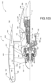
- FIGS. 101 and 103 are partial schematic views of a gas turbine engine 110 suspended from an engine pylon P within an engine nacelle assembly N, which is typical of an aircraft designed for subsonic flight.
- the engine pylon P or other support structure is typically mounted to an aircraft wing W, however, the engine pylon P may alternatively extend from other aircraft structure such as an aircraft empennage or tail assembly.
- the gas turbine engine 110 may include a core engine C within a core nacelle 112 that houses a low-pressure spool 114 and a high-pressure spool 124.
- the low-pressure spool 114 may include a low-pressure compressor 116 and low pressure turbine 118.
- the low-pressure spool 114 may be coupled to drive a fan 120 either directly or through a gear train 122.
- the high-pressure spool 124 may include a high-pressure compressor 126 and a high-pressure turbine 128.
- a combustor 130 may be arranged between the high-pressure compressor 126 and the high-pressure turbine 128.
- the low and high-pressure spools 114 and 124 may rotate about an engine axis A.
- the engine 110 may be a high-bypass geared architecture aircraft engine. Airflow enters a fan nacelle 134, which at least partially surrounds the core nacelle 112. The fan 120 communicates airflow into the core nacelle 112 to power the low-pressure compressor 116 and the high-pressure compressor 126. Core airflow compressed by the low-pressure compressor 116 and the high-pressure compressor 126 is mixed with the fuel in the combustor 130 and expanded over the high-pressure turbine 128 and low-pressure turbine 118. The turbines 128 and 118 are coupled to the spools 124 and 114 to rotationally drive the compressors 126 and 116, respectively, and the fan section 120 through the optional gear train 122. A core engine exhaust exits the core nacelle 112 through a core nozzle 108 disposed between the core nacelle 112 and the tail cone 132.
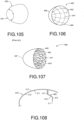
- a prior art spinner 430 and a nose cap 431 are shown that form the flow path forward of the fan blades 432 (see FIGS. 101-103 ).
- the spinner 430 and the nacelle inlet 193 influence the blade inlet air profile.
- the spinner 430 must, by regulation, resist impact from hail and bird strikes.
- the prior art spinner 430 may be fabricated from a pre-impregnated KEVLAR ® composite.
- the spinner 430 may be autoclaved or oven cured.
- the spinner 430 is typically a separate part from the nose cap 431, which may also be fabricated from a resin-impregnated KEVLAR ® composite that is compression molded. With these manufacturing methods, the most cost-effective way to add stiffness to the spinner 430 or nose cap 431 is to increase the thicknesses, thus adding weight in addition to material and processing costs.
- FIGS. 106, 107, 108 Improved light weight and stiff forward cones 440, 450, 470 are shown in FIGS. 106, 107, 108 respectively.
- the unitary forward cones 440, 450, 470 may replace the combination of the separate spinner 430 and nose cap 431.
- the forward cones 440, 450, 470 are injection molded and, in the case of the cones 440, 450, may be provided with reinforcements in the form of ribs 441, 442 in the circumferential and/or axial directions respectively.
- the ribs 441, 442 add stiffness to the forward cone without adding overall thickness or significant weight to the forward cones 440, 450.
- the number of circumferential ribs 441 may range from about two (2) to about 20, inclusive.
- the number of axial ribs 442 may range from about three (3) to about 32, inclusive.
- optional shear ties or ribs 443 connecting intersections of the circumferential and axial ribs 441, 442 may also be used to add additional stiffness to the overall structure.
- the area enclosed by the intersecting circumferential and axial ribs 441, 442 essentially form rectangles at the aft ends 444, 445 of the forward cones 440, 450 respectively and transition to trapezoids (and finally triangles, if the ribs are carried all the way to the forward ends 446, 447 of the cones 440, 450 respectively.
- shear ties or ribs 443 shown in FIG. 107 may be incorporated between all such enclosed areas, in alternating areas (like a chess board), in alternating rows or columns, etc., as required to deliver the necessary stiffness and other relevant properties.
- the ribs 441, 442, 443 may require a draft angle for removal from the mold tool (not shown), and a thickness and height of the ribs 441, 442, 443 may primarily be a function of the cone thickness due to shrinkage concerns. Regardless, the quantity and spacing of the ribs 441, 442 and the optional shear ties or ribs 443 and the overall thickness of forward cones 440, 450, 470 (with and without the ribs 441, 442 and shear ties 443) may be optimized. The ribs 441, 442, 443 do not have to be evenly spaced.
- injection molded polymeric substrates 311 form cores for the forward cones 440, 450, 470 that may be plated using a thin activation layer of copper to activate the polymeric substrate 311.
- the metallic layer(s) 312 may be applied by electroless plating, electroplating, or electroforming to a thickness ranging from about 0.004 to about 0.05 inches (from about 101.6 microns to about 1.27 mm).
- the metallic layer(s) 312 may be formed from one or more metals including, but not limited: nickel; cobalt; copper; iron; gold; silver; palladium; rhodium; chromium; zinc; tin; cadmium; and alloys with any of the foregoing elements comprising at least 50 wt.% of the alloy; and combinations thereof.
- Plating may be performed in multiple steps by masking certain areas of the molded article to yield different thicknesses or no plating in certain areas.
- a customized plating thickness profile can also be achieved by tailored racking (including shields, thieves, conformal anodes, etc.).
- the plating of the polymeric substrate 311 produces lightweight forward cones 440, 450, 470 with high specific strength and resistance to certain environmental concerns, e.g., erosion. Variations in the desired wall thickness or thickness of the polymeric substrate 311 may be easily accommodated in the molding process.
- the exemplary substrate 311 is injection-molded and may be formed from one or more polymers selected from the group consisting of condensation polyimides; addition polyimides; epoxy cured with aliphatic and/or aromatic amines and/or anhydrides; cyanate esters; phenolics; polyesters; polybenzoxazine; polyurethanes; polyacrylates; polymethacrylates; silicones (thermoset); and combinations thereof.
- the polymeric material of the polymeric substrate 311 may be structurally reinforced with materials that may include carbon, metal, or glass.
- the fiber- reinforced polymeric substrate 311 may include a plurality of layers to form a composite layup structure.
- the forward cones 440, 450, 470 necessarily include mounting features (of which only a flange 471 is shown in FIGS. 108 ). Some of these features (e.g., flanges) may be bonded to the polymeric substrate 311 ( FIG. 104 ) using a suitable adhesive after molding but before plating to simplify the mold tooling. A similar approach can be taken with additional features, such as the ribs 441, 442 and 443 (i.e., the can be integral in the mold tooling or bonded on after molding to simplify that process.
- one-piece, injection-molded and plated forward cone may be manufactured for a lower cost than prior art nose caps and spinners.
- the disclosed forward cone may be unitary, thereby replacing two parts (a nose cap and a spinner) with a single unitary forward nosecone.
- Disclosed one-piece, injection-molded cores that are plated with a metallic layer can be manufactured for a much lower cost than KEVLAR composites of the prior art.
- the disclosed forward cones are lighter and new designs may be fabricated with shorter lead times.
- the plated metallic layer(s) provides resistance to erosion while typical prior art spinners require an additional coating for erosion resistance.
- the disclosed nosecones may include reinforcing elements in the form of an internal ribbed structure designed to carry and distribute static and impact loads throughout the forward cone more efficiently than a constant thickness structure. Therefore, the wall thickness of the forward cone may be reduced to save weight.
- a spinner attachment ring may be used to attach a spinner or nosecone to a non-rotating hub, a rotating hub, or a fan rotor (not shown).
- spinner attachment rings may also transmit loads and may serve secondary functions such as retaining locks, etc.
- Spinner attachment rings are typically made of a metal, such as titanium, iron, or aluminum. These types of rings tend to be heavy and expensive.
- the spinner attachment ring 460 may include a polymeric substrate 311 and at least one metallic layer 312 as shown in FIG. 104 .
- the exemplary substrate 311 is injection molded and may include any one or more polymers selected from the group consisting of condensation polyimides; addition polyimides; epoxy cured with aliphatic and/or aromatic amines and/or anhydrides; cyanate esters; phenolics; polyesters; polybenzoxazine; polyurethanes; polyacrylates; polymethacrylates; silicones (thermoset); and combinations thereof.
- the polymeric material of the polymeric substrate 311 may be structurally reinforced with materials that may include carbon, metal, or glass.
- the fiber-reinforced polymeric substrate 311 may include a plurality of layers to form a composite layup structure.
- the metallic layer 312 may include one or more layers.
- the metallic layer(s) may be applied by electroless plating, electroplating, or electroforming to a thickness ranging from about 0.001 to about 1 inch (from about 25.4 microns to about 2.54 cm), locally.
- An average plating thickness may range from about 0.01 to about 0.075 inches (from about 254 microns to about 1.91 mm). These thickness ranges provide resistance to erosion, impact, etc. and the option to finish more aggressively to meet tight tolerances, surface finish requirements, etc.
- the metallic layer 312 may be formed from one or more metals including, but not limited: nickel; cobalt; copper; iron; gold; silver; palladium; rhodium; chromium; zinc; tin; cadmium; and alloys with any of the foregoing elements comprising at least 50 wt.% of the alloy; and combinations thereof.
- the metallic layer(s) 312 may be applied in multiple steps by masking certain areas of the attachment ring to yield different thicknesses in areas of interest, such as platforms or flanges. Such a customized plating thickness profile may also be achieved by tailored racking (includes shields, thieves, etc.). In addition, a thicker metallic layer(s) 312 allows for more aggressive machining, finishing, etc. to achieve the desired surface roughness, tolerances, etc. Such a multi-step process allows for optimization of attachment ring properties, with respect to fire, structural support, surface characteristics, etc. without adding undue weight to the attachment ring 460.
- attachment ring 460 may be fabricated in multiple segments that are joined by any a conventional process (e.g., ultrasonic, laser, friction and friction-stir welding processes; traditional welding processes; adhesives; mitered joints with or without adhesive) before plating. Because the metallic layer 312 is thick enough to provide significant structural strength and rigidity, the method of joining segments will likely not be a strength limiting factor.
- plated polymer attachment rings are disclosed that have applications beyond attaching a spinner or forward cone to a hub.
- the disclosed attachment rings are relatively inexpensive to manufacture due to the high-throughput molding and plating processes used to make the rings.
- Some component surfaces of gas turbine engines require protection against erosion and deicing capability.
- Current materials that are relatively erosion resistant include metals, ceramics, and some polymers. It is desirable to simultaneously provide an erosion resistant material that also repels or selectively directs water and/or prevents ice buildup on the component surfaces.
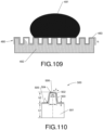
- FIG. 109 disclosed herein is a technique to impart a designed texture onto or into a surface 480 of an erosion resistant material used to fabricate a plated polymer spinner or forward cone.
- the textured surface 480 is designed to control the contact angle of the wetting fluid 481 (water) to direct the fluid 481 off the textured surface 480 and/or to prevent ice formation on the textured surface 480. Additional treatments can be performed to further enhance the functionality of the textured surface 480.
- At least one metallic layer 483 is plated on top of a textured polymeric substrate 482, which can render the textured surface 480 with even more resistance to erosion and super-hydrophobicity to prevent water attachment, and thus, to minimize ice buildup/adhesion.
- the substrate 482 may include, but is not limited to: polyetherimide (PEI); polyimide; polyether ether ketone (PEEK); polyether ketone ketone (PEKK); polysulfone; polyamide; polyphenylene sulfide; polyester; polyimide; and combinations thereof.
- thermoset materials may include, but are not limited to: condensation polyimides; addition polyimides; epoxy cured with aliphatic and/or aromatic amines and/or anhydrides; cyanate esters; phenolics; polyesters; polybenzoxazine; polyurethanes; polyacrylates; polymethacrylates; silicones (thermoset); and combinations thereof.
- the polymeric material of the polymeric substrate 482 may be structurally reinforced with materials that may include carbon, metal, or glass.
- the fiber-reinforced polymeric substrate 482 may include a plurality of layers to form a composite layup structure.
- the metallic layer(s) 483 may be formed from one or more metals including, but not limited: nickel; cobalt; copper; iron; gold; silver; palladium; rhodium; chromium; zinc; tin; cadmium; and alloys with any of the foregoing elements comprising at least 50 wt.% of the alloy; and combinations thereof.
- Plating may be performed in multiple steps by masking certain areas of the molded article to yield different thicknesses or no plating in certain areas.
- a customized plating thickness profile can also be achieved by tailored racking (including shields, thieves, conformal anodes, etc.).
- the metallic layer(s) 483 provide erosion and fatigue resistance.
- the metallic layer 483 may include one or more layers, preferably with a non-hydrophilic top-most layer.
- the metallic layer(s) 483 may be applied by electroless plating, electroplating, or electro forming to a thickness of about 10% of the texture dimension h.
- texture plated polymer surfaces are disclosed, for example, a textured plated polymer forward cones, nosecones or spinners.
- the textured plated polymer design saves both weight and costs and can generate a textured metallic layer of a uniform thickness.
- the polymeric substrate 501 may be formed of at least polymer selected from the group consisting of polyetherimide (PEI); polyimide; polyether ether ketone (PEEK); polyether ketone ketone (PEKK); polysulfone; polyamide; polyphenylene sulfide; polyester; polyimide; and combinations thereof.
- PEI polyetherimide
- PEEK polyether ether ketone
- PEKK polyether ketone ketone
- polysulfone polyamide
- polyphenylene sulfide polyester
- polyimide polyimide
- thermoset materials may include, but are not limited to: condensation polyimides; addition polyimides; epoxy cured with aliphatic and/or aromatic amines and/or anhydrides; cyanate esters; phenolics; polyesters; polybenzoxazine; polyurethanes; polyacrylates; polymethacrylates; silicones (thermoset); and combinations thereof.
- the polymeric material of the polymeric substrate 501 may be structurally reinforced with materials that may include carbon, metal, or glass.
- the fiber-reinforced polymeric substrate 501 may include a plurality of layers to form a composite layup structure.
- the metallic layer(s) 502 may include one or more layers.
- the metallic layer(s) 502 may be applied by electroless plating, electroplating, or electro forming to a thickness ranging from about 0.001 to about 0.5 inches (from about 25.4 microns to about 12.7 mm), locally.
- An average plating thickness may range from about 0.004 to about 0.3 inches (from about 101.6 microns to about 7.62 mm). These thickness ranges provides resistance to erosion, impact, FOD, etc. and the option to finish more aggressively to meet tight tolerances, surface finish requirements, etc.
- the plating of the metallic layer(s) 502 may be carried out in multiple steps by masking certain areas of the polymeric substrate 501 to yield different plating thicknesses (or no plating) in areas of interest.
- Such a customized plating thickness profile may also be achieved by tailored racking (including shields, thieves, conformal anodes, etc.). Tailored racking allows for an optimization of properties for the impact-resistant plated polymer structure 500 with respect to fire resistance, structural support, surface characteristics, etc. without adding undue weight to the structure 500.
- the metal layer(s) 502 may be formed from one or more metals including, but not limited: nickel; cobalt; copper; iron; gold; silver; palladium; rhodium; chromium; zinc; tin; cadmium; and alloys with any of the foregoing elements comprising at least 50 wt.% of the alloy; and combinations thereof.
- the impact-resistant plated polymer structure 500 may be fabricated in multiple segments that may be are joined by a conventional process (e.g., ultrasonic, laser, friction or friction-stir welding processes; traditional welding processes; adhesives; mitered joints with or without adhesive) before plating. Such segments of a final structure 500 may be produced and plated separately, and subsequently bonded together by transient liquid phase (TLP) bonding. Features such as inserts or details may be added (using an adhesive, riveting, etc.) to the structure 500 after the plating process.
- TLP transient liquid phase
- One or more polymeric coatings 503 may also be applied to impact-resistant plated polymer structure 500 to yield a lightweight, stiff and strong polymer appearing (non-conductive) component.
- the polymeric coating(s) 503 may be applied by a conventional process, such as spray coating or dip coating, and may be applied to localized regions only, if desired.
- FIG. 110 illustrates molding parameters for a polymeric substrate 501 having reinforcing ribs 504.
- the molding parameters for the ribs 504 illustrated in FIG. 110 include: (1) the thickness hi of polymeric substrate 501 (the sheet area between ribs 504); (2) the height h 2 of the ribs 504; (3) the base width Wi of the ribs 504; (4) the tip width w 2 of the ribs 504; (5) the draft angle 0 of the ribs 504; (6) the rib fillet radius r; and (7) the plating thickness t.
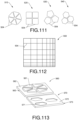
- various rib patterns 510, 520, 530, 540 are disclosed for arranging continuous ribs 504 on surface 505 of the polymeric substrate 501 ( FIG. 110 ).
- the rib patterns 510, 520, 530, 540 provide the plated polymer structure 500 with isotropic properties when they are utilized in a repeating fashion. The efficiency of the final structure 500 will vary and depend upon the specific shape or rib pattern 510, 520, 530, 540 chosen.
- the ribs 504 of the patterns 510, 520, 530, 540 may be flanged structural integrity.
- Combinations of rib patterns 510, 520, 530, 540 may also be used, for example one combination pattern may involve six hexagons surrounding a seventh hexagon that is filled with six triangles.
- the possible variations are too numerous to list individually here, as will be apparent to those skilled in the art.
- FIG. 112 is another disclosed rib pattern 550 that is an irregular grid. Regular grids may be used as well.
- FIG. 113 illustrates two unit-cell impact-resistant patterns 560, 570 that may be applied uniformly or only in local areas where more impact resistance is required.
- the pattern 560 includes triangular-shaped protrusions 561 that extend upward from the surface 562 of the molded polymeric substrate 563.
- the pattern 570 includes through-holes or recesses 571 that extend into or through the surface 572 of the molded polymeric substrate 573.
- the pattern 560 includes triangular-shaped protrusions while the pattern 570 includes hexagonal-shaped holes or recesses. Obviously, other shapes and combinations of shapes may be used as will be apparent to those skilled in the art.
- the patterns 510, 520, 530, 540, 550 560, 570 illustrated in FIGS. 111-112 are mere examples that can be extended upon. Furthermore, the combinations of the rib patterns 510, 520, 530, 540, 550, 560, 570 may be used, as desired, to achieve customized impact-resistance properties and redistribution of accompanying loads.
- Nosecones for ballistic applications such as launching missiles, mortars, rockets, model rockets or weather/atmospheric rockets, are typically a body of revolution of an aerodynamic, application specific shape.
- the nosecone must resist erosion and wear due to handling, and is required to maintain its shape to preserve aerodynamic properties.
- weight is a concern as it directly correlates to the amount of propellant, which is a costly factor, required to reach a desired altitude, target, or velocity.
- the structural and impact capability of the nosecone may be adjusted to control penetration into a target by adjusting the thickness of the applied plating.
- FIG. 114 illustrates a ballistic nosecone, constructed in accordance with the present invention, generally referred to by reference numeral 74.
- the ballistic nosecone 74 may include a polymeric substrate 76 at its core and one or more metallic plating 78 applied to one or more outer surface of the polymeric substrate 76. As shown, a portion of metallic plating 78 is partially removed to reveal the polymeric substrate 76.
- the polymeric substrate 76 may be formed from a thermoplastic or thermoset material.
- Suitable thermoplastic materials may include, but are not limited to, polyetherimide (PEI), thermoplastic polyimide, polyether ether ketone (PEEK), polyether ketone ketone (PEKK), polysulfone, polyamide, polyphenyl sulfide, polyester, polyimide, nylon, and combinations thereof.
- thermoset materials may include, but are not limited to, condensation polyimides, addition polyimides, epoxy cured with aliphatic and/or aromatic amines and/or anhydrides, cyanate esters, phenolics, polyesters, polybenzoxazine, polyurethanes, polyacrylates, polymethacrylates, silicones (thermoset), and combinations thereof.
- the polymeric material of the polymeric substrate 76 may be structurally reinforced with reinforcing materials which may include carbon, metal, glass, or other suitable materials.
- the polymeric substrate 76 may be formed into a desired ballistic nosecone 74 from the selected thermoplastic or thermoset materials, and optional reinforcement materials, by injection molding.
- the polymeric substrate 76 is injection molded so that the thickness may be in the range of about 0.050 inches (1.27 mm) to about 0.25 inches (6.35 mm), with localized areas ranging up to about 0.50 inches (12.7 mm).
- Selected portions of the ballistic nosecone 74, such as the walls, may be compression molded such that the polymeric substrate 76 thickness may be in the range of about 0.050 inches (1.27 mm) to about 2 inches (50.8 mm).
- additional mounting features such as flanges, bosses or other features, may be bonded on the unplated polymeric substrate 76 using any conventional adhesive bonding process.
- the polymeric substrate 76 may be fabricated in multiple segments and joined before plating using any conventional process including, but not limited to, ultrasonic welding, laser welding, friction welding, friction-stir welding, traditional welding, adhesive bonding, formation of mitered joints with or without adhesive, or combinations thereof.
- additional features such as inserts, flanges, bosses, or other features may be added to the ballistic nosecone 74 using conventional techniques known in the industry.
- segments of the polymeric substrate 76 may be plated with metallic plating 78 before being joined together, and subsequently, may be joined together by transient liquid phase (TLP) bonding to provide a more robust bond between the plated polymeric segments comprising the ballistic nosecone 74.
- TLP transient liquid phase
- the metallic plating 78 may include one or more layers.
- the thickness of the metallic plating 78 may be in the range of about 0.001 inches (0.0254 mm) to about 0.050 inches (1.27 mm), locally, with an overall average thickness in the range of about 0.004 inches (0.1016 mm) to 0.040 inches (1.016 mm), but other metallic plating thicknesses may also apply.
- the metallic plating 78 may not be a uniform thickness, but may be tailored to yield different thicknesses in specific regions to resist certain conditions such as fire, erosion, impact or foreign-object damage (FOD), to provide the option to finish more aggressively to meet tight tolerances or surface finish requirements, and to provide increased structural support or surface characteristics without adding undue weight to the ballistic nosecone 74 as a whole.
- Tailored thicknesses of the metallic plating 78 may be achieved by masking certain areas of the polymeric substrate 76 during the metal deposition process. Instead of masking, this may also be achieved using tailored racking techniques apparent to those of ordinary skill in the art such as, but not limited to, shields, current thieves, and/or conformal anodes.
- the metallic plating 78 may be formed from any platable metallic material such as, but not limited to, nickel, cobalt, copper, iron, gold, silver, palladium, rhodium, chromium, zinc, tin, cadmium, and alloys with any of the foregoing elements comprising at least 50 wt.% of the alloy, or combinations thereof.
- polymeric coatings may also be applied to plated ballistic nosecone 74 parts to produce a light-weight, stiff, and strong polymeric appearing (non-conductive) part.
- This polymeric coating may be applied by conventional processes such as, but not limited to, spray coating or dip coating, and may be applied to localized regions only, if desired.
- FIG. 115 illustrates a series of steps which may be performed to fabricate the ballistic nosecone 74.
- the polymeric substrate 76 may be formed into a desired shape from selected thermoplastic or thermoset materials, and optional reinforcement materials, by injection moulding.
- the polymeric substrate 76 may be formed as separate segments by injection moulding and then appropriately joined at a joining interface by any conventional process.
- the outer surfaces which are selected for plating with a metallic plating 78 layer may be prepared for receiving a plating catalyst in a variety of ways such as, but not limited to, etching, abrasion, reactive ion etching, or ionic activation, as shown in box 86.
- the catalyst may be a palladium layer although platinum and gold are also possibilities.
- the catalyst may have a thickness on the atomic scale.
- the prepared outer surfaces of the polymeric substrate 76 may then be suitably activated and metalized using processes well known in the industry.
- At least one metallic plating 78 may be deposited on selected activated outer surfaces of the polymeric substrate 76 by metal deposition methods apparent to those skilled in the art such as, but not limited to, electrolytic plating, electroless plating, and electroforming.
- the metallic plating 78 may be supplied with a polymeric coating to produce a light-weight, stiff, and strong polymeric appearing (non-conductive) component.
- FIG. 116 illustrates an alternative series of steps which may be performed to fabricate the ballistic nosecone 74.
- the polymeric substrate 76 segments may be joined together after being plated instead of being joined together before plating.
- the polymeric substrate 74 may be formed as separate segments from selected thermoplastic or thermoset materials, and optional reinforcement materials, by injection moulding.
- the outer surfaces of the polymeric substrate 76 segments which are selected for plating may be prepared for receiving a plating catalyst in a variety of ways such as, but not limited to, etching, abrasion, reactive ion etching, or ionic activation, as shown in box 96.
- the catalyst may have a thickness on the atomic scale, and may be a layer of palladium, platinum, gold, or other suitable materials.
- the prepared polymeric substrate segments may then be suitably activated and metalized using processes well known in the industry.
- at least one metallic plating 78 may be deposited on selected active outer surfaces of polymeric substrate 76 segments by metal deposition methods apparent to those skilled in the art such as, but not limited to, electrolytic plating, electroless plating, and electroforming.
- a transient liquid phase (TLP) bonding process may be performed to join the plated polymeric segments together so as to provide a more robust bond between the plated polymeric substrate 76 segments comprising the ballistic nosecone 74, as illustrated in box 102.
- TLP transient liquid phase
- a polymeric coating may be applied to produce a light-weight, stiff, and strong polymeric appearing (non-conductive) component.
- the plated polymeric ballistic nosecone can offer cost and weight savings, by reducing the amount of propellant required for launching, as compared to traditional materials and processes.
- the high-throughput molding and plating processes of the present invention can also provide production schedule savings. Production scheduling savings can also be increased because the plating and polymeric materials are readily available and are not single sourced.
- complex ballistic nosecone geometries can be accommodated by producing multiple polymeric segments and joining them together before or after plating.
- the plated polymeric ballistic nosecone provides structural reinforcement, impact capability, penetration control, or other desired properties. Additionally, the plated polymeric ballistic nosecone is erosion and wear resistant. Overall, plated polymeric ballistic nosecone parts, components, or component assembly durability is significantly improved as compared to traditional polymeric ballistic nosecone parts, components, or component assembly.
- plated polymer structures and components may provide impact resistance against both hard and soft body objects while yielding lighter and/or less costly structures and components as compared to traditional manufacturing techniques.
- Plated polymer materials such as plated polymeric substrates, plated polymeric composite substrates and plated polymeric composite layup structures may be used to form lightweight but strong nosecone components that can form parts of gas turbine engines, and may be used for sound attenuation, etc.
- the plated polymeric gas turbine engine components may offer cost and/or weight savings compared to baseline parts.
- the plated metallic layers provide properties such as erosion resistance that can remove the need for erosion coatings on a composite case or cover.
Description
- This disclosure relates to nosecone components for a gas turbine engine and methods of fabricating the nosecone components. The methods involve plating one or more metallic layers onto injection molded polymeric articles, producing lightweight plated polymer nosecone components that can be incorporated into gas turbine engines.
- Metal parts tend to be heavy due to the high densities of most metals. In certain instances, removing material from a metal part can lead to weight savings. For example, the stresses imposed upon a metal part in service may be analyzed. Typically, there are areas of the metal part that have little or no stress as well as highly stressed areas. An ideal metal part may contain a sufficient amount of metal in highly stressed areas to transmit the necessary loads and perform the function of the part. However, such an ideal part would contain less or no material in areas with little or no stress, respectively, thereby reducing the weight of the metal part to an idealized minimum. Therefore, there is a need for improved methods of providing metal parts that are lightweight but strong enough in high stress areas to perform the function of the part.
- However, removing material from the metal part by conventional means, such as machining, laser drilling, etc., is both difficult and costly. Further, removing material from a metal part can lead to reduced material properties of the part, which may be unacceptable. Thus, simply removing metal from a formed metal part is less than ideal in certain parts and situations.
- Gas turbine engines designed for aircraft include thousands of metal parts. Because the weight of an aircraft, including the engine, is directly related to fuel consumption, engine and aircraft manufacturers are constantly seeking new technologies that will help them reduce the weight of their engines and aircraft respectively. One strategy involves substituting traditional metal parts for lightweight polymer or composite parts. For example, non-metal containment structures for gas turbine engines may include, for example, KEVLAR® (a registered trademark of E.I. Dupont de Nemours & Company) or another ballistic fabric wrapped around a case. Containment systems that include fabric are more weight efficient than allmetal containment cases, but nonetheless add weight to the engine.
- Additive manufacturing (AM) or three-dimensional (3D) printing is a process of making a three-dimensional solid object of virtually any shape from a digital model. AM is achieved by depositing successive layers of material in different cross-sectional shapes. AM is considered distinct from traditional machining techniques, which mostly rely on the removal of material by methods such as cutting or drilling, i.e., subtractive processes. A materials printer usually performs AM processes using digital technology. Since the start of the twenty-first century there has been a large growth in the sales of these machines, and while the price has dropped substantially, AM remains costly. Despite its high cost, though, AM is used in many fields, including aerospace.
- Less costly alternatives to AM include various molding processes, such as blow molding, injection molding, compression molding, and others that will be apparent to those skilled in the art. Blow molding processes begin with melting the molding material and forming it into a parison or preform. The parison is a tube-like piece of plastic with a hole in one end through which compressed air can pass through. The parison is clamped into a mold and air is pumped into the parison. The air pressure pushes the molding material outwards to match the interior surface of the mold. Once the molding material has cooled and hardened, the mold opens and the part is ejected. In contrast, injection molding includes injecting molding material for the part into a heated barrel, mixing, and forcing the molding material into a mold cavity where the molding material cools and hardens to the configuration of the cavity. Compression molding is a method of molding in which the preheated molding material is placed in an open mold cavity. The mold is closed and pressure is applied to force the material into contact with all mold areas, while heat and pressure are maintained until the molding material has cured.
- For many molding processes, hard tooling is used to form the mold or die. While hard tooling can provide a high dimensional repeatability, hard tooling is very heavy and cumbersome and can present a safety hazard when moved or handled. Further, fabricating hard tooling is time consuming and costly. As a result, hard tooling is normally too expensive and time consuming for short production runs and/or for the fabrication of test parts. Thus, the ability to quickly fabricate tooling to support short production runs and/or test runs of composite materials is desired.
- Blow molding and injection molding cannot be used if the polymer to be molded is in the form of a composite with a plurality of layers or plies, i.e., a composite layup structure. Composites are materials made from two or more constituent materials with significantly different physical or chemical properties that, when combined, produce a material with characteristics different from the individual components. The individual components remain separate and distinct within the finished structure. Typically, composite layup structures can be molded or shaped using compression molding, resin transfer molding (RTM) or vacuum assisted resin transfer molding (VARTM), all of which utilize hard tooling that typically include details machined into one or more blocks of metal that form the mold.
- Composites can also include reinforcing fibers or matrices. The fibers or matrices may be formed from ceramic, metal, combinations of ceramic and metal, concrete and various other inorganic and organic materials. Organic matrix composites (OMCs) may include polyimides and/or bismaleimides (BMIs) because they can be used at higher temperatures than other commonly used organic reinforcing materials, such as epoxies. Such high-temperature OMCs may be processed by autoclave molding, compression molding, or resin-transfer molding. These processes all require lengthy cure and post-cure cycles as well as hard tooling that is difficult and costly to make. Further, only tooling with limited geometrical complexity can be produced. Thus, improved methods for molding OMCs are also desired.
- One inexpensive method of forming a metallic layer on a surface of a molded polymer article is electroless plating. To ensure adhesion of the plated film to the molded polymer article, the surface of the polymer article may need to be prepared by etching, abrading, or ionic activation. The most common types of metals used for plating on polymers are copper, silver, and nickel, although other metals can be used.
- Electrolytic plating is the deposition of a metal on a conductive material using an electric current. A molded polymer article must first be made conductive to be electrolytically plated. This can be done through electroless plating or by the use of conductive additives such as carbon. The article to be electrolytically plated is immersed in a solution of metal salts connected to a cathodic current source, and an anodic conductor is immersed in the bath to complete the electrical circuit. Electric current flows from the cathode to the anode, and the electron flow reduces the dissolved metal ions to pure metal on the cathodic surface. The anode is usually made from the same metal, and can dissolve during the electroplating process, thereby replenishing the bath.
- The operating temperature of a plated polymer article, component or part may be limited by the polymeric substrate. Thus, parts for a gas turbine engine may not be able to be fabricated from a polymer material or a reinforced polymer material if the part is within a line-of-sight to a heat source, such as a combustor, which may transfer heat to the part by radiation. Because of the operating conditions of a gas turbine engine and the need to save weight, lightweight polymer parts that can withstand relatively high operating temperatures for polymers (>150°C) are needed in the aircraft and/or gas turbine engine industries.
- Another issue associated with gas turbine engines is noise. Suppression of gas turbine engine noise has become an important field of research due to airport regulations and aircraft noise certification requirements that govern the maximum noise level that aircraft are allowed to produce. Further, because the principal sources of noise from a commercial aircraft are the engines, reducing noise emitted by such engines is desirable. Thus, there is a need for gas turbine engine structural components that are both lightweight and that include sound attenuation properties.
WO 2012/110383 discloses a metal plated polymer in which the metal is fine grained or amorphous.
US 4403075 andUS 4739115 disclose fire resistant composites or laminates for use as structural components in aircraft. - Plated polymer components for gas turbine engines are disclosed. The disclosed components include an injection molded polymeric substrate plated with at least one metallic layer and, optionally, at least one polymer layer.
- Methods are also disclosed for fabricating such plated polymer components of gas turbine engines. The disclosed methods include forming a polymer into a desired shape having an outer surface. The outer surface may be prepared to receive a catalyst and the outer surface may be activated with the catalyst. A first metal may then be plated onto the outer surface and the catalyst to form a structure, optionally followed by plating one or more additional layers until a desired thickness is reached. The plated structure may optionally be coated with a polymeric coating.
- In one aspect of the invention, a nosecone component for a gas turbine engine is provided. The component includes at least one injection moulded polymeric substrate forming the nosecone component and has at least one exposed surface. At least one metallic plating layer is deposited on the at least one exposed surface of the at least one polymeric substrate. The at least one polymeric substrate is formed into one of an attachment ring, a spinner and a unitary forward cone having a plurality of circumferential ribs and a plurality of axial ribs.
- In a further aspect of the invention, the at least one polymeric substrate is formed into a unitary forward cone having a plurality of circumferential ribs and a plurality of axial ribs. A plurality of shear ribs may connect intersections of the plurality of circumferential ribs and the plurality of axial ribs.
- In yet a further aspect of the invention, the at least one polymeric substrate is formed to include a plurality of reinforcing ribs, preferably wherein each rib of the plurality of reinforcing ribs includes a first height, a second height, a first width, and a second width, the second height being greater than the first height, and/or wherein the plurality of reinforcing ribs is a plurality of continuous ribs.
- In yet another aspect of the invention, the at least one exposed surface is texturized to direct a fluid off of the at least one exposed surface.
- In yet another aspect of the invention, a gas turbine engine is provided which includes a hub and an attachment ring coupled to the hub. The attachment ring includes a first at least one injection moulded polymeric substrate having a first at least one exposed surface. A first at least one metallic plating layer is deposited on the first at least one exposed surface.
- In yet another aspect of the invention, a unitary forward cone is coupled to the attachment ring, the unitary forward cone including a second at least one polymeric substrate having a second at least one exposed surface and a second at least one metallic plating layer deposited on the second at least one exposed surface.
- In still yet another aspect of the invention, a spinner is coupled to the attachment ring, the spinner including a second at least one polymeric substrate having a second at least one exposed surface and a second at least one metallic plating layer deposited on the second at least one exposed surface.
- In an even further aspect of the invention, the second at least one polymeric substrate is formed to include a plurality of reinforcing ribs, preferably wherein each rib of the plurality of reinforcing ribs includes a first height, a second height, a first width, and a second width, the second height being greater than the first height.
- In yet another aspect of the invention, a method of fabricating a nosecone component is provided. The method comprises injection moulding at least one polymeric substrate in a desired shape of the nosecone component and depositing at least one metallic plating layer on at least one exposed surface of the at least one polymeric substrate, wherein the desired shape is one of a spinner, a unitary forward cone, an attachment ring for a gas turbine engine, and a ballistic nosecone, and further including the step of providing a plurality of circumferential ribs and a plurality of axial ribs adjacent to the at least one metallic plating layer.
- In an even further aspect of the invention, another step is forming the at least one polymeric substrate to include a plurality of reinforcing ribs.
- In still an even further aspect of the invention, each rib of the plurality of reinforcing ribs includes a first height, a second height, a first width, and a second width, the second height being greater than the first height.
- Other aspects and features of the disclosed systems and methods will be appreciated from reading the attached detailed description in conjunction with the included drawings features. Moreover, selected aspects and features of one example embodiment may be combined with various selected aspects and features of other example embodiments.
-
-
FIG. 101 is a sectional view of a gas turbine engine. -
FIG. 102 is a partial sectional view of a gas turbine engine illustrating an engine static structure case arrangement on the lower half thereof with an accessory system mounted thereto. -
FIG. 103 is another sectional view of a gas turbine engine. -
FIG. 104 is a sectional view of a plated polymeric substrate. -
FIG. 105 isa perspective view of a prior art nose cap and spinner. -
FIG. 106 is a perspective view of a disclosed plated polymer forward cone. -
FIG. 107 is a perspective view of another disclosed plated polymer forward cone. -
FIG. 108 is a sectional view of yet another disclosed plated polymer forward cone and a disclosed plated polymer attachment ring. -
FIG. 109 is a sectional view of a textured plated polymeric substrate made in accordance with this invention. -
FIG. 110 is a sectional view illustrating the dimensional parameters for a structural rib molded into a polymeric substrate that is plated with at least one metallic layer and optionally covered by at least one polymer layer. -
FIG. 111 illustrates four rib patterns that may be molded into the polymeric substrate shown inFIG. 110 for enhancing impact resistant properties of the substrate. -
FIG. 112 illustrates in irregular grid pattern for rib(s) that may be molded into the polymeric substrate ofFIG. 110 for enhancing impact resistant properties of the substrate. -
FIG. 113 illustrates two additional patterns of protrusions and recesses, respectively, that may be molded into the polymeric substrate ofFIG. 110 for enhancing impact-resistant properties of the substrate. -
FIG. 114 is a front perspective view of a ballistic nosecone constructed in accordance with the present invention. -
FIG. 115 is a flow-chart diagram, illustrating the steps involved in the formation of a plated polymeric ballistic nosecone, in accordance with a method of the present invention. -
FIG. 116 is a flow-chart diagram, illustrating an alternative series of steps involved in the formation of a plated polymeric ballistic nosecone, in accordance with a method of the present invention. -
FIGS. 101 and103 are partial schematic views of agas turbine engine 110 suspended from an engine pylon P within an engine nacelle assembly N, which is typical of an aircraft designed for subsonic flight. The engine pylon P or other support structure is typically mounted to an aircraft wing W, however, the engine pylon P may alternatively extend from other aircraft structure such as an aircraft empennage or tail assembly. - The
gas turbine engine 110 may include a core engine C within acore nacelle 112 that houses a low-pressure spool 114 and a high-pressure spool 124. The low-pressure spool 114 may include a low-pressure compressor 116 andlow pressure turbine 118. The low-pressure spool 114 may be coupled to drive afan 120 either directly or through agear train 122. The high-pressure spool 124 may include a high-pressure compressor 126 and a high-pressure turbine 128. Acombustor 130 may be arranged between the high-pressure compressor 126 and the high-pressure turbine 128. The low and high-pressure spools - The
engine 110 may be a high-bypass geared architecture aircraft engine. Airflow enters afan nacelle 134, which at least partially surrounds thecore nacelle 112. Thefan 120 communicates airflow into thecore nacelle 112 to power the low-pressure compressor 116 and the high-pressure compressor 126. Core airflow compressed by the low-pressure compressor 116 and the high-pressure compressor 126 is mixed with the fuel in thecombustor 130 and expanded over the high-pressure turbine 128 and low-pressure turbine 118. Theturbines spools compressors fan section 120 through theoptional gear train 122. A core engine exhaust exits thecore nacelle 112 through a core nozzle 108 disposed between thecore nacelle 112 and thetail cone 132. - Referring to
FIG. 105 , aprior art spinner 430 and anose cap 431 are shown that form the flow path forward of the fan blades 432 (seeFIGS. 101-103 ). Thespinner 430 and thenacelle inlet 193 influence the blade inlet air profile. Thespinner 430 must, by regulation, resist impact from hail and bird strikes. Theprior art spinner 430 may be fabricated from a pre-impregnated KEVLAR® composite. Thespinner 430 may be autoclaved or oven cured. Thespinner 430 is typically a separate part from thenose cap 431, which may also be fabricated from a resin-impregnated KEVLAR® composite that is compression molded. With these manufacturing methods, the most cost-effective way to add stiffness to thespinner 430 ornose cap 431 is to increase the thicknesses, thus adding weight in addition to material and processing costs. - Improved light weight and stiff
forward cones FIGS. 106, 107, 108 respectively. Theunitary forward cones separate spinner 430 andnose cap 431. Theforward cones cones ribs ribs forward cones circumferential ribs 441 may range from about two (2) to about 20, inclusive. The number of axial ribs 442 (spline-shaped, running forward to aft) may range from about three (3) to about 32, inclusive. As shown inFIG. 107 , optional shear ties orribs 443 connecting intersections of the circumferential andaxial ribs axial ribs forward cones cones ribs 443 shown inFIG. 107 may be incorporated between all such enclosed areas, in alternating areas (like a chess board), in alternating rows or columns, etc., as required to deliver the necessary stiffness and other relevant properties. - Due to the injection molding process, the
ribs ribs ribs ribs 443 and the overall thickness offorward cones ribs ribs - Referring back to
FIG. 104 and toFIG. 108 , injection moldedpolymeric substrates 311 form cores for theforward cones polymeric substrate 311. The metallic layer(s) 312 may be applied by electroless plating, electroplating, or electroforming to a thickness ranging from about 0.004 to about 0.05 inches (from about 101.6 microns to about 1.27 mm). The metallic layer(s) 312 may be formed from one or more metals including, but not limited: nickel; cobalt; copper; iron; gold; silver; palladium; rhodium; chromium; zinc; tin; cadmium; and alloys with any of the foregoing elements comprising at least 50 wt.% of the alloy; and combinations thereof. Plating may be performed in multiple steps by masking certain areas of the molded article to yield different thicknesses or no plating in certain areas. A customized plating thickness profile can also be achieved by tailored racking (including shields, thieves, conformal anodes, etc.). - The plating of the
polymeric substrate 311 produces lightweightforward cones polymeric substrate 311 may be easily accommodated in the molding process. Theexemplary substrate 311 is injection-molded and may be formed from one or more polymers selected from the group consisting of condensation polyimides; addition polyimides; epoxy cured with aliphatic and/or aromatic amines and/or anhydrides; cyanate esters; phenolics; polyesters; polybenzoxazine; polyurethanes; polyacrylates; polymethacrylates; silicones (thermoset); and combinations thereof. Optionally, the polymeric material of thepolymeric substrate 311 may be structurally reinforced with materials that may include carbon, metal, or glass. The fiber- reinforcedpolymeric substrate 311 may include a plurality of layers to form a composite layup structure. - The
forward cones flange 471 is shown inFIGS. 108 ). Some of these features (e.g., flanges) may be bonded to the polymeric substrate 311 (FIG. 104 ) using a suitable adhesive after molding but before plating to simplify the mold tooling. A similar approach can be taken with additional features, such as theribs - Thus, one-piece, injection-molded and plated forward cone (i.e., a combination nose cap and spinner) may be manufactured for a lower cost than prior art nose caps and spinners. The disclosed forward cone may be unitary, thereby replacing two parts (a nose cap and a spinner) with a single unitary forward nosecone. Disclosed one-piece, injection-molded cores that are plated with a metallic layer can be manufactured for a much lower cost than KEVLAR composites of the prior art. The disclosed forward cones are lighter and new designs may be fabricated with shorter lead times. The plated metallic layer(s) provides resistance to erosion while typical prior art spinners require an additional coating for erosion resistance. The disclosed nosecones may include reinforcing elements in the form of an internal ribbed structure designed to carry and distribute static and impact loads throughout the forward cone more efficiently than a constant thickness structure. Therefore, the wall thickness of the forward cone may be reduced to save weight.
- In a gas turbine engine 110 (
FIGS. 101-103 ), a spinner attachment ring may be used to attach a spinner or nosecone to a non-rotating hub, a rotating hub, or a fan rotor (not shown). In general, spinner attachment rings may also transmit loads and may serve secondary functions such as retaining locks, etc. Spinner attachment rings are typically made of a metal, such as titanium, iron, or aluminum. These types of rings tend to be heavy and expensive. - An exemplary
spinner attachment ring 460 is shown inFIG. 108 . Thespinner attachment ring 460 may include apolymeric substrate 311 and at least onemetallic layer 312 as shown inFIG. 104 . Theexemplary substrate 311 is injection molded and may include any one or more polymers selected from the group consisting of condensation polyimides; addition polyimides; epoxy cured with aliphatic and/or aromatic amines and/or anhydrides; cyanate esters; phenolics; polyesters; polybenzoxazine; polyurethanes; polyacrylates; polymethacrylates; silicones (thermoset); and combinations thereof. Optionally, the polymeric material of thepolymeric substrate 311 may be structurally reinforced with materials that may include carbon, metal, or glass. The fiber-reinforcedpolymeric substrate 311 may include a plurality of layers to form a composite layup structure. - The
metallic layer 312 may include one or more layers. The metallic layer(s) may be applied by electroless plating, electroplating, or electroforming to a thickness ranging from about 0.001 to about 1 inch (from about 25.4 microns to about 2.54 cm), locally. An average plating thickness may range from about 0.01 to about 0.075 inches (from about 254 microns to about 1.91 mm). These thickness ranges provide resistance to erosion, impact, etc. and the option to finish more aggressively to meet tight tolerances, surface finish requirements, etc. Themetallic layer 312 may be formed from one or more metals including, but not limited: nickel; cobalt; copper; iron; gold; silver; palladium; rhodium; chromium; zinc; tin; cadmium; and alloys with any of the foregoing elements comprising at least 50 wt.% of the alloy; and combinations thereof. - The metallic layer(s) 312 may be applied in multiple steps by masking certain areas of the attachment ring to yield different thicknesses in areas of interest, such as platforms or flanges. Such a customized plating thickness profile may also be achieved by tailored racking (includes shields, thieves, etc.). In addition, a thicker metallic layer(s) 312 allows for more aggressive machining, finishing, etc. to achieve the desired surface roughness, tolerances, etc. Such a multi-step process allows for optimization of attachment ring properties, with respect to fire, structural support, surface characteristics, etc. without adding undue weight to the
attachment ring 460. - Further, the
attachment ring 460 may be fabricated in multiple segments that are joined by any a conventional process (e.g., ultrasonic, laser, friction and friction-stir welding processes; traditional welding processes; adhesives; mitered joints with or without adhesive) before plating. Because themetallic layer 312 is thick enough to provide significant structural strength and rigidity, the method of joining segments will likely not be a strength limiting factor. - Thus, plated polymer attachment rings are disclosed that have applications beyond attaching a spinner or forward cone to a hub. The disclosed attachment rings are relatively inexpensive to manufacture due to the high-throughput molding and plating processes used to make the rings.
- Some component surfaces of gas turbine engines require protection against erosion and deicing capability. Current materials that are relatively erosion resistant include metals, ceramics, and some polymers. It is desirable to simultaneously provide an erosion resistant material that also repels or selectively directs water and/or prevents ice buildup on the component surfaces.
- Turning to
FIG. 109 , disclosed herein is a technique to impart a designed texture onto or into asurface 480 of an erosion resistant material used to fabricate a plated polymer spinner or forward cone. Thetextured surface 480 is designed to control the contact angle of the wetting fluid 481 (water) to direct the fluid 481 off thetextured surface 480 and/or to prevent ice formation on thetextured surface 480. Additional treatments can be performed to further enhance the functionality of thetextured surface 480. - At least one
metallic layer 483 is plated on top of a texturedpolymeric substrate 482, which can render thetextured surface 480 with even more resistance to erosion and super-hydrophobicity to prevent water attachment, and thus, to minimize ice buildup/adhesion. Thesubstrate 482 may include, but is not limited to: polyetherimide (PEI); polyimide; polyether ether ketone (PEEK); polyether ketone ketone (PEKK); polysulfone; polyamide; polyphenylene sulfide; polyester; polyimide; and combinations thereof. Suitable thermoset materials may include, but are not limited to: condensation polyimides; addition polyimides; epoxy cured with aliphatic and/or aromatic amines and/or anhydrides; cyanate esters; phenolics; polyesters; polybenzoxazine; polyurethanes; polyacrylates; polymethacrylates; silicones (thermoset); and combinations thereof. Optionally, the polymeric material of thepolymeric substrate 482 may be structurally reinforced with materials that may include carbon, metal, or glass. The fiber-reinforcedpolymeric substrate 482 may include a plurality of layers to form a composite layup structure. The metallic layer(s) 483 may be formed from one or more metals including, but not limited: nickel; cobalt; copper; iron; gold; silver; palladium; rhodium; chromium; zinc; tin; cadmium; and alloys with any of the foregoing elements comprising at least 50 wt.% of the alloy; and combinations thereof. Plating may be performed in multiple steps by masking certain areas of the molded article to yield different thicknesses or no plating in certain areas. A customized plating thickness profile can also be achieved by tailored racking (including shields, thieves, conformal anodes, etc.). - The metallic layer(s) 483 provide erosion and fatigue resistance. The
metallic layer 483 may include one or more layers, preferably with a non-hydrophilic top-most layer. The metallic layer(s) 483 may be applied by electroless plating, electroplating, or electro forming to a thickness of about 10% of the texture dimension h. - Thus, as opposed to prior art hardening or coating techniques including nitriding and aluminizing to avoid erosion, texture plated polymer surfaces are disclosed, for example, a textured plated polymer forward cones, nosecones or spinners. The textured plated polymer design saves both weight and costs and can generate a textured metallic layer of a uniform thickness.
- Many components of a gas turbine engine must be resistant to impact events from both hard objects (rocks, debris, ice, etc.) and soft objects (bird strikes, etc.). Components of other engines, such as truck, automotive, marine, etc., also must be resistant to such impact events. Components made from traditional materials such metals, polymers, composites, ceramics, etc. often must be made heavier or with more complex geometries to meet impact-resistant requirements. Heavier components and/or components with more complex geometries increase cost and manufacturing lead time as well as substantial design and manufacturing efforts.
- Turning to
FIG. 110 , disclosed herein are impact-resistant platedpolymer structures 500, which include apolymeric substrate 501 covered by at least onemetallic layer 502. Anexemplary substrate 501 is injection-molded. Thepolymeric substrate 501 may be formed of at least polymer selected from the group consisting of polyetherimide (PEI); polyimide; polyether ether ketone (PEEK); polyether ketone ketone (PEKK); polysulfone; polyamide; polyphenylene sulfide; polyester; polyimide; and combinations thereof. Suitable thermoset materials may include, but are not limited to: condensation polyimides; addition polyimides; epoxy cured with aliphatic and/or aromatic amines and/or anhydrides; cyanate esters; phenolics; polyesters; polybenzoxazine; polyurethanes; polyacrylates; polymethacrylates; silicones (thermoset); and combinations thereof. Optionally, the polymeric material of thepolymeric substrate 501 may be structurally reinforced with materials that may include carbon, metal, or glass. The fiber-reinforcedpolymeric substrate 501 may include a plurality of layers to form a composite layup structure. - The metallic layer(s) 502 may include one or more layers. The metallic layer(s) 502 may be applied by electroless plating, electroplating, or electro forming to a thickness ranging from about 0.001 to about 0.5 inches (from about 25.4 microns to about 12.7 mm), locally. An average plating thickness may range from about 0.004 to about 0.3 inches (from about 101.6 microns to about 7.62 mm). These thickness ranges provides resistance to erosion, impact, FOD, etc. and the option to finish more aggressively to meet tight tolerances, surface finish requirements, etc. The plating of the metallic layer(s) 502 may be carried out in multiple steps by masking certain areas of the
polymeric substrate 501 to yield different plating thicknesses (or no plating) in areas of interest. Such a customized plating thickness profile may also be achieved by tailored racking (including shields, thieves, conformal anodes, etc.). Tailored racking allows for an optimization of properties for the impact-resistant platedpolymer structure 500 with respect to fire resistance, structural support, surface characteristics, etc. without adding undue weight to thestructure 500. The metal layer(s) 502 may be formed from one or more metals including, but not limited: nickel; cobalt; copper; iron; gold; silver; palladium; rhodium; chromium; zinc; tin; cadmium; and alloys with any of the foregoing elements comprising at least 50 wt.% of the alloy; and combinations thereof. - The impact-resistant plated
polymer structure 500 may be fabricated in multiple segments that may be are joined by a conventional process (e.g., ultrasonic, laser, friction or friction-stir welding processes; traditional welding processes; adhesives; mitered joints with or without adhesive) before plating. Such segments of afinal structure 500 may be produced and plated separately, and subsequently bonded together by transient liquid phase (TLP) bonding. Features such as inserts or details may be added (using an adhesive, riveting, etc.) to thestructure 500 after the plating process. One or morepolymeric coatings 503 may also be applied to impact-resistant platedpolymer structure 500 to yield a lightweight, stiff and strong polymer appearing (non-conductive) component. The polymeric coating(s) 503 may be applied by a conventional process, such as spray coating or dip coating, and may be applied to localized regions only, if desired. - Turning to
FIGS. 110-113 ,FIG. 110 illustrates molding parameters for apolymeric substrate 501 having reinforcingribs 504. The molding parameters for theribs 504 illustrated inFIG. 110 include: (1) the thickness hi of polymeric substrate 501 (the sheet area between ribs 504); (2) the height h2 of theribs 504; (3) the base width Wi of theribs 504; (4) the tip width w2 of theribs 504; (5) the draft angle 0 of theribs 504; (6) the rib fillet radius r; and (7) the plating thickness t. In general, the rib parameters illustrated inFIG. 110 are related according to the following equations:


- Turning to
FIG. 111 ,various rib patterns continuous ribs 504 on surface 505 of the polymeric substrate 501 (FIG. 110 ). Therib patterns polymer structure 500 with isotropic properties when they are utilized in a repeating fashion. The efficiency of thefinal structure 500 will vary and depend upon the specific shape orrib pattern ribs 504 of thepatterns rib patterns -
FIG. 112 is another disclosedrib pattern 550 that is an irregular grid. Regular grids may be used as well.FIG. 113 illustrates two unit-cell impact-resistant patterns pattern 560 includes triangular-shapedprotrusions 561 that extend upward from thesurface 562 of the moldedpolymeric substrate 563. In contrast, thepattern 570 includes through-holes or recesses 571 that extend into or through thesurface 572 of the moldedpolymeric substrate 573. Thepattern 560 includes triangular-shaped protrusions while thepattern 570 includes hexagonal-shaped holes or recesses. Obviously, other shapes and combinations of shapes may be used as will be apparent to those skilled in the art. Thepatterns FIGS. 111-112 are mere examples that can be extended upon. Furthermore, the combinations of therib patterns - Nosecones for ballistic applications, such as launching missiles, mortars, rockets, model rockets or weather/atmospheric rockets, are typically a body of revolution of an aerodynamic, application specific shape. The nosecone must resist erosion and wear due to handling, and is required to maintain its shape to preserve aerodynamic properties. As with any object in flight, weight is a concern as it directly correlates to the amount of propellant, which is a costly factor, required to reach a desired altitude, target, or velocity. In addition to the weight of the nosecone, the structural and impact capability of the nosecone may be adjusted to control penetration into a target by adjusting the thickness of the applied plating.
Thus, there is a need for a lightweight cost effective nosecone that is easily produced and resistant to erosion and wear. -
FIG. 114 illustrates a ballistic nosecone, constructed in accordance with the present invention, generally referred to byreference numeral 74. It is noted that theballistic nosecone 74, as depicted, is only exemplary and other ballistic nosecone designs and configurations can also be made within the scope of the present disclosure. Theballistic nosecone 74 may include apolymeric substrate 76 at its core and one or moremetallic plating 78 applied to one or more outer surface of thepolymeric substrate 76. As shown, a portion ofmetallic plating 78 is partially removed to reveal thepolymeric substrate 76. - The
polymeric substrate 76 may be formed from a thermoplastic or thermoset material. Suitable thermoplastic materials may include, but are not limited to, polyetherimide (PEI), thermoplastic polyimide, polyether ether ketone (PEEK), polyether ketone ketone (PEKK), polysulfone, polyamide, polyphenyl sulfide, polyester, polyimide, nylon, and combinations thereof. Suitable thermoset materials may include, but are not limited to, condensation polyimides, addition polyimides, epoxy cured with aliphatic and/or aromatic amines and/or anhydrides, cyanate esters, phenolics, polyesters, polybenzoxazine, polyurethanes, polyacrylates, polymethacrylates, silicones (thermoset), and combinations thereof. Optionally, the polymeric material of thepolymeric substrate 76 may be structurally reinforced with reinforcing materials which may include carbon, metal, glass, or other suitable materials. - The
polymeric substrate 76 may be formed into a desiredballistic nosecone 74 from the selected thermoplastic or thermoset materials, and optional reinforcement materials, by injection molding. Thepolymeric substrate 76 is injection molded so that the thickness may be in the range of about 0.050 inches (1.27 mm) to about 0.25 inches (6.35 mm), with
localized areas ranging up to about 0.50 inches (12.7 mm). Selected portions of theballistic nosecone 74, such as the walls, may be compression molded such that thepolymeric substrate 76 thickness may be in the range of about 0.050 inches (1.27 mm) to about 2 inches (50.8 mm). - To simplify the mold tooling, additional mounting features, such as flanges, bosses or other features, may be bonded on the unplated
polymeric substrate 76 using any conventional adhesive bonding process. Alternatively, thepolymeric substrate 76 may be fabricated in multiple segments and joined before plating using any conventional process including, but not limited to, ultrasonic welding, laser welding, friction welding, friction-stir welding, traditional welding, adhesive bonding, formation of mitered joints with or without adhesive, or combinations thereof. After the plating process, additional features such as inserts, flanges, bosses, or other features may be added to theballistic nosecone 74 using conventional techniques known in the industry. Furthermore, as another alternative, segments of thepolymeric substrate 76 may be plated withmetallic plating 78 before being joined together, and subsequently, may be joined together by transient liquid phase (TLP) bonding to provide a more robust bond between the plated polymeric segments comprising theballistic nosecone 74. - The
metallic plating 78 may include one or more layers. The thickness of themetallic plating 78 may be in the range of about 0.001 inches (0.0254 mm) to about 0.050 inches (1.27 mm), locally, with an overall average thickness in the range of about 0.004 inches (0.1016 mm) to 0.040 inches (1.016 mm), but other metallic plating thicknesses may also apply. Themetallic plating 78 may not be a uniform thickness, but may be tailored to yield different thicknesses in specific regions to resist certain conditions such as fire, erosion, impact or foreign-object damage (FOD), to provide the option to finish more aggressively to meet tight tolerances or surface finish requirements, and to provide increased structural support or surface characteristics without adding undue weight to theballistic nosecone 74 as a whole. Tailored thicknesses of themetallic plating 78 may be achieved by masking certain areas of thepolymeric substrate 76 during the metal deposition process. Instead of masking, this may also be achieved using tailored racking techniques apparent to those of ordinary skill in the art such as, but not limited to, shields, current thieves, and/or conformal anodes. Themetallic plating 78 may be formed from any platable metallic material such as, but not limited to, nickel, cobalt, copper, iron, gold, silver, palladium, rhodium, chromium, zinc, tin, cadmium, and alloys with any of the foregoing elements comprising at least 50 wt.% of the alloy, or combinations thereof. - Optionally, polymeric coatings may also be applied to plated
ballistic nosecone 74 parts to produce a light-weight, stiff, and strong polymeric appearing (non-conductive) part. This polymeric coating may be applied by conventional processes such as, but not limited to, spray coating or dip coating, and may be applied to localized regions only, if desired. -
FIG. 115 illustrates a series of steps which may be performed to fabricate theballistic nosecone 74. As illustrated inbox 80, thepolymeric substrate 76 may be formed into a desired shape from selected thermoplastic or thermoset materials, and optional reinforcement materials, by injection moulding. Alternatively, as shown inboxes polymeric substrate 76 cannot be formed using injection moulding directly, or cannot be formed cost effectively, thepolymeric substrate 76 may be formed as separate segments by injection moulding and then appropriately joined at a joining interface by any conventional process. - Following the formation of the
polymeric substrate 76, the outer surfaces which are selected for plating with ametallic plating 78 layer may be prepared for receiving a plating catalyst in a variety of ways such as, but not limited to, etching, abrasion, reactive ion etching, or ionic activation, as shown inbox 86. The catalyst may be a palladium layer although platinum and gold are also possibilities. The catalyst may have a thickness on the atomic scale. As illustrated inbox 88, the prepared outer surfaces of thepolymeric substrate 76 may then be suitably activated and metalized using processes well known in the industry. Subsequent to activation with the catalyst, as shown inbox 90, at least onemetallic plating 78 may be deposited on selected activated outer surfaces of thepolymeric substrate 76 by metal deposition methods apparent to those skilled in the art such as, but not limited to, electrolytic plating, electroless plating, and electroforming. Optionally, as shown inbox 92, after thepolymeric substrate 76 has been plated with at least onemetallic plating 78, themetallic plating 78 may be supplied with a polymeric coating to produce a light-weight, stiff, and strong polymeric appearing (non-conductive) component. -
FIG. 116 illustrates an alternative series of steps which may be performed to fabricate theballistic nosecone 74. InFIG. 116 , thepolymeric substrate 76 segments may be joined together after being plated instead of being joined together before plating. As illustrated inbox 94, thepolymeric substrate 74 may be formed as separate segments from selected thermoplastic or thermoset materials, and optional reinforcement materials, by injection moulding. Subsequently, the outer surfaces of thepolymeric substrate 76 segments which are selected for plating may be prepared for receiving a plating catalyst in a variety of ways such as, but not limited to, etching, abrasion, reactive ion etching, or ionic activation, as shown inbox 96. As in the previous series of steps detailed above, the catalyst may have a thickness on the atomic scale, and may be a layer of palladium, platinum, gold, or other suitable materials. Referring tobox 98, the prepared polymeric substrate segments may then be suitably activated and metalized using processes well known in the industry. Following activation, as shown inbox 100, at least onemetallic plating 78 may be deposited on selected active outer surfaces ofpolymeric substrate 76 segments by metal deposition methods apparent to those skilled in the art such as, but not limited to, electrolytic plating, electroless plating, and electroforming. - Once
polymeric substrate 76 segments have been plated with at least onemetallic plating 78, a transient liquid phase (TLP) bonding process may be performed to join the plated polymeric segments together so as to provide a more robust bond between the platedpolymeric substrate 76 segments comprising theballistic nosecone 74, as illustrated inbox 102. Optionally, as shown inbox 104, after platedpolymeric substrate 76 segments have been TLP bonded, a polymeric coating may be applied to produce a light-weight, stiff, and strong polymeric appearing (non-conductive) component. - From the foregoing, it can therefore be seen that the plated polymeric ballistic nosecone can offer cost and weight savings, by reducing the amount of propellant required for launching, as compared to traditional materials and processes. The high-throughput molding and plating processes of the present invention can also provide production schedule savings. Production scheduling savings can also be increased because the plating and polymeric materials are readily available and are not single sourced. During production, complex ballistic nosecone geometries can be accommodated by producing multiple polymeric segments and joining them together before or after plating. The plated polymeric ballistic nosecone provides structural reinforcement, impact capability, penetration control, or other desired properties. Additionally, the plated polymeric ballistic nosecone is erosion and wear resistant. Overall, plated polymeric ballistic nosecone parts, components, or component assembly durability is significantly improved as compared to traditional polymeric ballistic nosecone parts, components, or component assembly.
- Thus, plated polymer structures and components may provide impact resistance against both hard and soft body objects while yielding lighter and/or less costly structures and components as compared to traditional manufacturing techniques.
- Plated polymer materials such as plated polymeric substrates, plated polymeric composite substrates and plated polymeric composite layup structures may be used to form lightweight but strong nosecone components that can form parts of gas turbine engines, and may be used for sound attenuation, etc. The plated polymeric gas turbine engine components may offer cost and/or weight savings compared to baseline parts. The plated metallic layers provide properties such as erosion resistance that can remove the need for erosion coatings on a composite case or cover.
Claims (11)
- A nosecone component for a gas turbine engine, the component comprising:at least one injection moulded polymeric substrate (311) forming the nosecone component and having at least one exposed surface; andat least one metallic plating layer (312) deposited on the at least one exposed surface of the at least one polymeric substrate (311),wherein the at least one polymeric substrate (311) is formed into one of an attachment ring (460), a spinner (430) and a unitary forward cone (440) having a plurality of circumferential ribs (441) and a plurality of axial ribs (442).
- The component of claim 1 being the unitary forward cone, and further including a plurality of shear ribs connecting intersections of the plurality of circumferential ribs (411) and the plurality of axial ribs (442).
- The component of any one of the preceding claims, wherein the at least one polymeric substrate (311) is formed to include a plurality of reinforcing ribs, preferablywherein each rib of the plurality of reinforcing ribs includes a first height, a second height, a first width, and a second width, the second height greater than the first height, and/orwherein the plurality of reinforcing ribs is a plurality of continuous ribs.
- The component of any one of the preceding claims, wherein the at least one exposed surface is texturized to direct a fluid (481) off of the at least one exposed surface.
- A gas turbine engine, the engine comprising:a hub; andan attachment ring (460) as claimed in claim 1 coupled to the hub.
- The engine of claim 5, further including a unitary forward cone (440) coupled to the attachment ring (460), the unitary forward cone (440) including a second at least one polymeric substrate (311) having a second at least one exposed surface and a second at least one metallic plating layer (312) deposited on the second at least one exposed surface, preferably
wherein the unitary forward cone (440) includes a plurality of circumferential ribs (441) and a plurality of axial ribs (442). - The engine of claim 5 or 6, further including a spinner (430) coupled to the attachment ring (460), the spinner (430) including a second at least one polymeric substrate (311) having a second at least one exposed surface and a second at least one metallic plating layer (312) deposited on the second at least one exposed surface.
- The engine of claim 6, wherein the second at least one polymeric substrate (311) is formed to include a plurality of reinforcing ribs, preferably
wherein each rib of the plurality of reinforcing ribs includes a first height, a second height, a first width, and a second width, the second height greater than the first height. - A method of fabricating a nosecone component, the method comprising:injection moulding at least one polymeric substrate (311) in a desired shape of the nosecone component; anddepositing at least one metallic plating layer (312) on at least one exposed surface of the at least one polymeric substrate (311),wherein the desired shape is one of a spinner (430), a unitary forward cone (440), an attachment ring (460) for a gas turbine engine, and a ballistic nosecone, andfurther including the step of providing a plurality of circumferential ribs (441) and a plurality of axial ribs (442) adjacent to the at least one metallic plating layer (312).
- The method of claim 9, further including the step of forming the at least one polymeric substrate (311) to include a plurality of reinforcing ribs.
- The method of claim 10, wherein each rib of the plurality of reinforcing ribs includes a first height, a second height, a first width, and a second width, the second height greater than the first height.
Applications Claiming Priority (3)
| Application Number | Priority Date | Filing Date | Title |
|---|---|---|---|
| US201361844048P | 2013-07-09 | 2013-07-09 | |
| US201361843976P | 2013-07-09 | 2013-07-09 | |
| PCT/US2014/045985 WO2015017095A2 (en) | 2013-07-09 | 2014-07-09 | Plated polymer nosecone |
Publications (3)
| Publication Number | Publication Date |
|---|---|
| EP3019711A2 EP3019711A2 (en) | 2016-05-18 |
| EP3019711A4 EP3019711A4 (en) | 2017-05-10 |
| EP3019711B1 true EP3019711B1 (en) | 2023-11-01 |
Family
ID=52432540
Family Applications (1)
| Application Number | Title | Priority Date | Filing Date |
|---|---|---|---|
| EP14832491.6A Active EP3019711B1 (en) | 2013-07-09 | 2014-07-09 | Plated polymer nosecone |
Country Status (4)
| Country | Link |
|---|---|
| US (1) | US11267576B2 (en) |
| EP (1) | EP3019711B1 (en) |
| CA (1) | CA2917916A1 (en) |
| WO (1) | WO2015017095A2 (en) |
Families Citing this family (33)
| Publication number | Priority date | Publication date | Assignee | Title |
|---|---|---|---|---|
| WO2007021980A2 (en) | 2005-08-12 | 2007-02-22 | Isotron Corporation | Compositionally modulated composite materials and methods for making the same |
| BR122013014464B1 (en) | 2009-06-08 | 2020-10-20 | Modumetal, Inc | corrosion resistant multilayer coating on a substrate and electrodeposit method for producing a coating |
| DE102011108957B4 (en) * | 2011-07-29 | 2013-07-04 | Mtu Aero Engines Gmbh | A method for producing, repairing and / or replacing a housing, in particular an engine housing, and a corresponding housing |
| BR112015022078B1 (en) | 2013-03-15 | 2022-05-17 | Modumetal, Inc | Apparatus and method for electrodepositing a nanolaminate coating |
| EA201500949A1 (en) | 2013-03-15 | 2016-02-29 | Модьюметл, Инк. | METHOD OF FORMING A MULTILAYER COATING, A COATING FORMED BY THE ABOVE METHOD, AND A MULTILAYER COATING |
| CN105283587B (en) | 2013-03-15 | 2019-05-10 | 莫杜美拓有限公司 | Nano-stack coating |
| WO2014145771A1 (en) | 2013-03-15 | 2014-09-18 | Modumetal, Inc. | Electrodeposited compositions and nanolaminated alloys for articles prepared by additive manufacturing processes |
| WO2015006438A1 (en) | 2013-07-09 | 2015-01-15 | United Technologies Corporation | Plated polymer compressor |
| CA2917643A1 (en) * | 2013-07-09 | 2015-01-15 | United Technologies Corporation | Industrial products formed from plated polymers |
| EP3019710A4 (en) | 2013-07-09 | 2017-05-10 | United Technologies Corporation | Plated polymer fan |
| US9789664B2 (en) | 2013-07-09 | 2017-10-17 | United Technologies Corporation | Plated tubular lattice structure |
| EA201790643A1 (en) | 2014-09-18 | 2017-08-31 | Модьюметал, Инк. | METHOD AND DEVICE FOR CONTINUOUS APPLICATION OF NANO-LAYERED METAL COATINGS |
| AR102068A1 (en) * | 2014-09-18 | 2017-02-01 | Modumetal Inc | METHODS OF PREPARATION OF ITEMS BY ELECTRODEPOSITION AND ADDITIVE MANUFACTURING PROCESSES |
| US10472048B2 (en) * | 2014-12-02 | 2019-11-12 | United Technologies Corporation | Gas turbine engine spinner |
| US9845728B2 (en) * | 2015-10-15 | 2017-12-19 | Rohr, Inc. | Forming a nacelle inlet for a turbine engine propulsion system |
| DE102016101428A1 (en) * | 2016-01-27 | 2017-07-27 | Rolls-Royce Deutschland Ltd & Co Kg | Nose cone for a fan of an aircraft engine |
| US10273881B2 (en) * | 2016-04-06 | 2019-04-30 | General Electric Company | Foreign object damage screen for gas turbine system |
| BR112019004508A2 (en) | 2016-09-08 | 2019-06-04 | Modumetal Inc | methods for obtaining laminated coatings on workpieces and articles made therefrom |
| JP7105073B2 (en) * | 2017-03-23 | 2022-07-22 | 株式会社イノアックコーポレーション | Soundproof structure |
| EP3601641A1 (en) | 2017-03-24 | 2020-02-05 | Modumetal, Inc. | Lift plungers with electrodeposited coatings, and systems and methods for producing the same |
| CA3060619A1 (en) | 2017-04-21 | 2018-10-25 | Modumetal, Inc. | Tubular articles with electrodeposited coatings, and systems and methods for producing the same |
| US10677090B2 (en) * | 2017-05-10 | 2020-06-09 | General Electric Company | Component having co-bonded composite and metal rings and method of assembling same |
| US10900136B2 (en) | 2017-07-18 | 2021-01-26 | Honeywell International Inc. | Additive-based electroforming manufacturing methods and metallic articles produced thereby |
| US10369748B2 (en) * | 2017-10-26 | 2019-08-06 | Battelle Memorial Institute | Friction stirring interlocking of dissimilar materials |
| US10763715B2 (en) | 2017-12-27 | 2020-09-01 | Rolls Royce North American Technologies, Inc. | Nano-crystalline coating for magnet retention in a rotor assembly |
| FR3079818A1 (en) * | 2018-04-10 | 2019-10-11 | Airbus Operations (S.A.S.) | AIRCRAFT ENGINE NACELLE WITH A FROST PROTECTIVE SYSTEM AND METHOD FOR PROTECTING THE SAME |
| CN112272717B (en) | 2018-04-27 | 2024-01-05 | 莫杜美拓有限公司 | Apparatus, system, and method for producing multiple articles with nanolaminate coatings using rotation |
| US11433990B2 (en) | 2018-07-09 | 2022-09-06 | Rohr, Inc. | Active laminar flow control system with composite panel |
| JP2020012495A (en) * | 2018-07-17 | 2020-01-23 | キヤノン電子株式会社 | Cylindrical member and structure using the same |
| GB201816894D0 (en) | 2018-10-17 | 2018-11-28 | Rolls Royce Plc | Component shielding |
| KR102165363B1 (en) * | 2019-01-08 | 2020-10-14 | 주식회사 아이엠기술 | Coating method for preventing degassing from resin material aerospace member |
| US11143103B2 (en) * | 2019-04-10 | 2021-10-12 | Rolls-Royce Corporation | Nose cone and fan assembly |
| US20240018883A1 (en) * | 2022-07-15 | 2024-01-18 | The Boeing Company | Nacelle inlet assembly with composite lipskin |
Citations (1)
| Publication number | Priority date | Publication date | Assignee | Title |
|---|---|---|---|---|
| US5833435A (en) * | 1996-12-24 | 1998-11-10 | United Technologies Corporation | Inlet nose cone assembly and method for repairing the assembly |
Family Cites Families (225)
| Publication number | Priority date | Publication date | Assignee | Title |
|---|---|---|---|---|
| US1843886A (en) | 1929-07-25 | 1932-02-02 | American Propeller Company | Propeller |
| US2401247A (en) * | 1941-09-20 | 1946-05-28 | Goodrich Co B F | Spinner assembly |
| US2942300A (en) | 1957-09-11 | 1960-06-28 | Nat Res Corp | Method of forming stiff threads |
| US2959229A (en) | 1957-10-01 | 1960-11-08 | United Aircraft Corp | Nickel plated propeller blade |
| US3344515A (en) | 1961-04-21 | 1967-10-03 | Litton Systems Inc | Multilayer laminated wiring |
| DE1521152A1 (en) | 1965-07-16 | 1969-04-24 | Basf Ag | Metallization of plastic surfaces |
| US3573973A (en) | 1967-11-13 | 1971-04-06 | Ibm | High speed additive circuit process |
| US3560349A (en) | 1968-05-01 | 1971-02-02 | Budd Co | Method of electroforming containers having openings with thick sections at the openings |
| FR1593346A (en) | 1968-11-25 | 1970-05-25 | ||
| US3681209A (en) | 1970-10-27 | 1972-08-01 | Hooker Chemical Corp | Metal plating on nonconductive substrates |
| US3900320A (en) | 1971-09-30 | 1975-08-19 | Bell & Howell Co | Activation method for electroless plating |
| US4148945A (en) | 1974-02-04 | 1979-04-10 | The Dow Chemical Company | Process of metal plating on plastics |
| CA1053994A (en) | 1974-07-03 | 1979-05-08 | Amp Incorporated | Sensitization of polyimide polymer for electroless metal deposition |
| US3959433A (en) | 1974-09-06 | 1976-05-25 | Union Carbide Corporation | Method of warm runner injection molding phenolic resins with para-substituted phenol |
| US3953653A (en) | 1975-04-30 | 1976-04-27 | Phillips Petroleum Company | Method to treat a poly(arylene sulfide) surface |
| US4029838A (en) | 1975-09-24 | 1977-06-14 | The United States Of America As Represented By The Administrator Of The National Aeronautics And Space Administration | Hybrid composite laminate structures |
| US4070912A (en) | 1975-10-01 | 1978-01-31 | Mcnaughtan Thomas J | Temperature indicating compositions and devices |
| DE2728465C2 (en) | 1977-06-24 | 1982-04-22 | Preh, Elektrofeinmechanische Werke, Jakob Preh, Nachf. Gmbh & Co, 8740 Bad Neustadt | Printed circuit |
| US4192764A (en) | 1977-11-03 | 1980-03-11 | Western Electric Company, Inc. | Stabilizing composition for a metal deposition process |
| FR2443921A1 (en) | 1978-12-14 | 1980-07-11 | British Aerospace | ORGANS RESISTANT TO MECHANICAL DAMAGE AND GALVANOPLASTY OF RUBBER OR MATERIALS LIKE RUBBER |
| US4241129A (en) | 1978-12-15 | 1980-12-23 | The Dow Chemical Company | Delamination resistant multilayer metal/polymer composites |
| US4315970A (en) | 1980-02-11 | 1982-02-16 | Dow Corning Corporation | Adhesion of metals to solid substrates |
| US4403075A (en) | 1980-09-25 | 1983-09-06 | Mcdonnell Douglas Corporation | Flame resistant composition containing polymeric phosphorylated amides |
| US4739115A (en) | 1980-09-25 | 1988-04-19 | Mcdonnell Douglas Corporation | Poly phosphinoguanidine compounds |
| US4446191A (en) | 1980-10-27 | 1984-05-01 | Hitachi Chemical Company, Ltd. | Laminates comprising prepregs metal clad |
| US4417848A (en) | 1982-02-01 | 1983-11-29 | United Technologies Corporation | Containment shell for a fan section of a gas turbine engine |
| US4617977A (en) | 1982-07-03 | 1986-10-21 | Rolls-Royce Limited | Ceramic casting mould and a method for its manufacture |
| GB2136313B (en) | 1983-03-17 | 1985-09-18 | Premaberg | Air intake equipment |
| US4499157A (en) | 1983-05-31 | 1985-02-12 | Hughes Aircraft Company | Solderable plated plastic components and processes for manufacture and soldering |
| US4647714A (en) | 1984-12-28 | 1987-03-03 | Sohwa Laminate Printing Co., Ltd. | Composite sheet material for magnetic and electronic shielding and product obtained therefrom |
| US4815940A (en) | 1986-08-04 | 1989-03-28 | United Technologies Corporation | Fatigue strengthened composite article |
| US4888247A (en) | 1986-08-27 | 1989-12-19 | General Electric Company | Low-thermal-expansion, heat conducting laminates having layers of metal and reinforced polymer matrix composite |
| US4868071A (en) | 1987-02-24 | 1989-09-19 | Polyonics Corporation | Thermally stable dual metal coated laminate products made from textured polyimide film |
| US4992144A (en) | 1987-02-24 | 1991-02-12 | Polyonics Corporation | Thermally stable dual metal coated laminate products made from polyimide film |
| US4894124A (en) | 1988-02-16 | 1990-01-16 | Polyonics Corporation | Thermally stable dual metal coated laminate products made from textured polyimide film |
| US4774126A (en) | 1987-07-20 | 1988-09-27 | General Electric Company | Solderable thermoplastic structure |
| US4913062A (en) | 1987-07-24 | 1990-04-03 | Zeftek, Inc. | Segmented sliding sill wear plate |
| US4916110A (en) | 1988-11-01 | 1990-04-10 | W. L. Gore & Associates, Inc. | Microporous catalytic material and support structure |
| US5064509A (en) | 1990-09-28 | 1991-11-12 | Xerox Corporation | Multilayer belts formed by electrodeposition |
| US5252160A (en) * | 1990-11-15 | 1993-10-12 | Auto Air Composites, Inc. | Method of manufacturing a metal/composite spinner cone |
| JP2530785B2 (en) | 1991-12-04 | 1996-09-04 | 積水化学工業株式会社 | Method for manufacturing electric fusion joint |
| EP0575685B1 (en) | 1992-06-23 | 1997-01-15 | Sulzer Innotec Ag | Investment casting with wear surfaces |
| US6476487B2 (en) | 1992-10-30 | 2002-11-05 | Showa Denko K.K. | Solder circuit |
| US5556023A (en) | 1992-10-30 | 1996-09-17 | Showa Denko K.K. | Method of forming solder film |
| US5348446A (en) | 1993-04-28 | 1994-09-20 | General Electric Company | Bimetallic turbine airfoil |
| JPH06315919A (en) | 1993-04-30 | 1994-11-15 | Kikusui Kagaku Kogyo Kk | Manufacture of ceramic |
| JP3137527B2 (en) | 1994-04-21 | 2001-02-26 | 三菱重工業株式会社 | Gas turbine blade tip cooling system |
| US5656795A (en) | 1995-04-03 | 1997-08-12 | Schlegel Corporation | Segmented shielding structure for connector panels |
| JPH08309926A (en) | 1995-05-17 | 1996-11-26 | Nitto Boseki Co Ltd | Laminated sheet material and reed of loom produced therefrom |
| CA2193773A1 (en) | 1995-12-22 | 1997-06-23 | Paul C. Isenberg | Injection molding of long fiber reinforced thermoplastics |
| US5658506A (en) | 1995-12-27 | 1997-08-19 | Ford Global Technologies, Inc. | Methods of making spray formed rapid tools |
| US5630700A (en) | 1996-04-26 | 1997-05-20 | General Electric Company | Floating vane turbine nozzle |
| US6055786A (en) | 1996-05-30 | 2000-05-02 | Omnova Solutions Inc. | Heat weld indicator for thermoplastic roofing membrane |
| US5702584A (en) | 1996-07-01 | 1997-12-30 | Ford Motor Company | Enhanced plating adhesion through the use of metallized fillers in plastic substrate |
| US5839882A (en) | 1997-04-25 | 1998-11-24 | General Electric Company | Gas turbine blade having areas of different densities |
| GB9711080D0 (en) | 1997-05-29 | 1997-07-23 | Imperial College | Film or coating deposition on a substrate |
| US6356013B1 (en) | 1997-07-02 | 2002-03-12 | Candescent Intellectual Property Services, Inc. | Wall assembly and method for attaching walls for flat panel display |
| US6059533A (en) | 1997-07-17 | 2000-05-09 | Alliedsignal Inc. | Damped blade having a single coating of vibration-damping material |
| US5877240A (en) | 1997-09-26 | 1999-03-02 | Owens Corning Fiberglas Technology, Inc. | Sizing composition for glass fibers for reinforcement of engineered thermoplastic materials |
| KR20060095785A (en) | 1998-02-26 | 2006-09-01 | 이비덴 가부시키가이샤 | Multilayer printed wiring board having filled-via structure |
| US6248393B1 (en) | 1998-02-27 | 2001-06-19 | Parker-Hannifin Corporation | Flame retardant EMI shielding materials and method of manufacture |
| DE19812880A1 (en) | 1998-03-24 | 1999-09-30 | Bayer Ag | Shaped part and flexible film with protected conductor track and process for its production |
| DE19813592A1 (en) | 1998-03-27 | 1999-09-30 | Audi Ag | Flat composite body, in particular motor vehicle body element |
| US6278185B1 (en) | 1998-05-27 | 2001-08-21 | Intel Corporation | Semi-additive process (SAP) architecture for organic leadless grid array packages |
| US6087021A (en) | 1998-05-28 | 2000-07-11 | International Business Machines Corporation | Polymer with transient liquid phase bondable particles |
| US6129260A (en) | 1998-08-19 | 2000-10-10 | Fravillig Technologies Company | Solderable structures |
| US6092556A (en) | 1998-10-28 | 2000-07-25 | Bundy Corporation | Multi-wall tube |
| US6240970B1 (en) | 1999-04-01 | 2001-06-05 | Itt Manufacturing Enterprises, Inc. | Tubing for handling hydrocarbon materials and having an outer jacket layer adhered thereto |
| DE10084475T1 (en) | 1999-04-14 | 2003-06-18 | Pfister Price Inc | Process for coating plastics with metals and articles produced thereby |
| EP1244544A4 (en) | 1999-10-25 | 2003-01-29 | Rolls Royce Corp | Erosion-resistant coatings for organic matrix composites |
| JP4906210B2 (en) | 1999-10-26 | 2012-03-28 | ハウメット リサーチ コーポレイション | Multilayer core and manufacturing method thereof |
| US6725541B1 (en) | 2000-01-21 | 2004-04-27 | Rolls-Royce Plc | Flow directing element and a method of manufacturing a flow directing element |
| JP4410895B2 (en) | 2000-01-28 | 2010-02-03 | 関西ペイント株式会社 | Car body covering method |
| US6547210B1 (en) | 2000-02-17 | 2003-04-15 | Wright Medical Technology, Inc. | Sacrificial insert for injection molding |
| US6982116B1 (en) | 2000-02-18 | 2006-01-03 | Praxair S.T. Technology, Inc. | Coatings on fiber reinforced composites |
| US6358014B1 (en) * | 2000-03-24 | 2002-03-19 | General Electric Company | Composite spinner and method of making the same |
| AU2001248179A1 (en) | 2000-04-05 | 2001-10-23 | Decoma Exterior Trim Inc. | Process for the direct metal-plating of a plastic substrate |
| AU1500902A (en) | 2000-10-11 | 2002-04-22 | Chemetall Gmbh | Method for coating metallic surfaces with an aqueous composition, the aqueous composition and use of the coated substrates |
| CN1304332C (en) | 2000-12-19 | 2007-03-14 | 通用电气公司 | Method for forming complex ceramic shapes |
| GB0102169D0 (en) * | 2001-01-27 | 2001-03-14 | Rolls Royce Plc | A gas turbine engine nose cone |
| JP2002292613A (en) | 2001-03-28 | 2002-10-09 | Kyocera Corp | Method for manufacturing ceramic molding |
| US6772086B2 (en) * | 2001-08-30 | 2004-08-03 | Vibe-Tech Solutions, Inc. | Process to determine impact location |
| EP1296046A3 (en) | 2001-09-24 | 2004-07-14 | Goodrich Control Systems Limited | Electronic engine controller |
| US7452454B2 (en) | 2001-10-02 | 2008-11-18 | Henkel Kgaa | Anodized coating over aluminum and aluminum alloy coated substrates |
| DE10149522A1 (en) | 2001-10-08 | 2003-04-10 | Bayer Ag | Plastic-metal composite component for frame structures |
| US6722086B2 (en) * | 2001-12-04 | 2004-04-20 | Alfred H. Boots | Modular structure system |
| US6551063B1 (en) | 2001-12-20 | 2003-04-22 | General Electric Company | Foil formed structure for turbine airfoil trailing edge |
| US20030183416A1 (en) | 2002-03-29 | 2003-10-02 | White Jerry L. | Method of electrically coupling an electronic component to a substrate |
| US7517490B2 (en) | 2002-10-16 | 2009-04-14 | Ngk Insulators, Ltd. | Method of manufacturing ceramic green body |
| US7007710B2 (en) | 2003-04-21 | 2006-03-07 | Predicant Biosciences, Inc. | Microfluidic devices and methods |
| EP1493843A1 (en) | 2003-07-03 | 2005-01-05 | ALSTOM Technology Ltd | Coated metallic component |
| DE10343761A1 (en) | 2003-09-22 | 2005-04-14 | Mtu Aero Engines Gmbh | Wear protection layer, component with such a wear protection layer and manufacturing process |
| US7287573B2 (en) | 2003-09-30 | 2007-10-30 | General Electric Company | Silicone binders for investment casting |
| GB2407142B (en) | 2003-10-15 | 2006-03-01 | Rolls Royce Plc | An arrangement for bleeding the boundary layer from an aircraft engine |
| JP2005171916A (en) | 2003-12-12 | 2005-06-30 | Kansai Electric Power Co Inc:The | Windmill blade |
| JP3736806B2 (en) | 2003-12-26 | 2006-01-18 | 三井金属鉱業株式会社 | Printed wiring board, manufacturing method thereof, and circuit device |
| JP2005219259A (en) | 2004-02-04 | 2005-08-18 | Mitsubishi Shindoh Co Ltd | Metallized polyimide film |
| US20050175813A1 (en) | 2004-02-10 | 2005-08-11 | Wingert A. L. | Aluminum-fiber laminate |
| DE602005025196D1 (en) | 2004-03-09 | 2011-01-20 | Bekaert Sa Nv | A METAL REINFORCEMENT ELEMENT COMPRISING A THERMOPLASTIC POLYMER MATERIAL COMPRISING COMPONENTS |
| US7246773B2 (en) | 2004-05-06 | 2007-07-24 | Goodrich Coporation | Low power, pulsed, electro-thermal ice protection system |
| US6943288B1 (en) | 2004-06-04 | 2005-09-13 | Schlegel Systems, Inc. | EMI foil laminate gasket |
| US20050274103A1 (en) * | 2004-06-10 | 2005-12-15 | United Technologies Corporation | Gas turbine engine inlet with noise reduction features |
| US7186092B2 (en) | 2004-07-26 | 2007-03-06 | General Electric Company | Airfoil having improved impact and erosion resistance and method for preparing same |
| US7565996B2 (en) | 2004-10-04 | 2009-07-28 | United Technologies Corp. | Transient liquid phase bonding using sandwich interlayers |
| US20060099370A1 (en) | 2004-11-08 | 2006-05-11 | Glass Lawrence G | Adhesive attachment assembly and roofing system |
| US7329875B2 (en) | 2004-11-23 | 2008-02-12 | General Electric Company | Detector array for imaging system and method of making same |
| US7387578B2 (en) | 2004-12-17 | 2008-06-17 | Integran Technologies Inc. | Strong, lightweight article containing a fine-grained metallic layer |
| US8545974B2 (en) | 2005-02-09 | 2013-10-01 | Laird Technologies, Inc. | Flame retardant EMI shields |
| US20100258344A1 (en) | 2005-02-09 | 2010-10-14 | Laird Technologies, Inc. | Flame retardant emi shields |
| US20060180348A1 (en) | 2005-02-16 | 2006-08-17 | Cloutier Bryan R | Flame retardant EMI shielding gasket |
| KR20070114137A (en) | 2005-02-24 | 2007-11-29 | 필킹톤 노쓰 아메리카, 인코포레이티드 | Anti-reflective, thermally insulated glazing articles |
| US20060222846A1 (en) | 2005-04-01 | 2006-10-05 | General Electric Company | Reflective and resistant coatings and methods for applying to composite structures |
| US7250194B2 (en) | 2005-04-07 | 2007-07-31 | Gmic, Corp. | Metal sprayed composite part |
| US20060235542A1 (en) | 2005-04-15 | 2006-10-19 | Zimmer Technology, Inc. | Flexible segmented bearing implant |
| US7568344B2 (en) | 2005-09-01 | 2009-08-04 | Frait & Whitney Canada Corp. | Hydrostatic flow barrier for flexible fuel manifold |
| US7830021B1 (en) | 2005-09-06 | 2010-11-09 | Rockwell Collins, Inc. | Tamper resistant packaging with transient liquid phase bonding |
| NL1030066C2 (en) | 2005-09-29 | 2007-03-30 | Gtm Consulting B V | Method for manufacturing a molded part from a composite material. |
| US7360997B2 (en) | 2005-10-06 | 2008-04-22 | General Electric Company | Vibration damper coating |
| BRPI0520633A2 (en) | 2005-11-03 | 2009-05-19 | Vestas Wind Sys As | wind turbine blade, wind turbine, oscillation damping means for damping oscillation or vibrations between edges of a wind turbine blade, method of damping damping of a wind turbine blade, and use of oscillation damping means at a wind turbine blade |
| EP1963168B1 (en) | 2005-12-06 | 2009-12-02 | Selle Royal S.P.A. | Ultra light saddle structure, particularly for pedal-driven vehicles and process for making its support frame |
| US7776447B2 (en) | 2006-01-23 | 2010-08-17 | Lexmark International, Inc. | Composite materials and fuser members having improved adhesion between a metal layer and a polyimide substrate |
| US7802613B2 (en) | 2006-01-30 | 2010-09-28 | United Technologies Corporation | Metallic coated cores to facilitate thin wall casting |
| KR101360158B1 (en) | 2006-03-29 | 2014-02-11 | 도레이 필름 카코우 가부시키가이샤 | Power feeding method, continuous electrolytic plating apparatus for web and method for manufacturing plastic film having plating film |
| KR20070104792A (en) | 2006-04-24 | 2007-10-29 | 성낙훈 | Electro-forming |
| IL175270A0 (en) | 2006-04-26 | 2006-09-05 | Acktar Ltd | Composite inorganic membrane for separation in fluid systems |
| KR100803214B1 (en) | 2006-06-28 | 2008-02-14 | 삼성전자주식회사 | Transfer film having organic polymer and method for formation of metal thin layer using the transfer film |
| JP5433416B2 (en) | 2006-08-08 | 2014-03-05 | ワールド プラパティーズ、 インコーポレイテッド | Circuit materials, circuits and multilayer circuit laminates |
| US7553514B2 (en) | 2006-08-28 | 2009-06-30 | 3M Innovative Properties Company | Antireflective article |
| JP4848901B2 (en) | 2006-09-07 | 2011-12-28 | 住友電装株式会社 | Method for manufacturing insert molded product and mold |
| US8273430B2 (en) | 2007-01-31 | 2012-09-25 | Senior Investments Gmbh | Metal/polymer laminate ducting and method for making same |
| US20110008164A1 (en) | 2007-03-23 | 2011-01-13 | Flodesign Wind Turbine Corporation | Wind turbine |
| US8088498B2 (en) | 2007-05-23 | 2012-01-03 | Hamilton Sundstrand Corporation | Electro-formed sheath for use on airfoil components |
| US8726665B2 (en) | 2007-06-05 | 2014-05-20 | The Boeing Company | Internal mixing of a portion of fan exhaust flow and full core exhaust flow in aircraft turbofan engines |
| WO2008151986A1 (en) | 2007-06-14 | 2008-12-18 | Basf Se | Flame retardant compositions |
| US20090008431A1 (en) | 2007-07-03 | 2009-01-08 | Kossi Zonvide | Solderable EMI Gasket and Grounding Pad |
| PL2014551T3 (en) * | 2007-07-09 | 2010-06-30 | Agusta Spa | Device and method for protecting an aircraft component from collision with flying objects |
| WO2009048676A1 (en) | 2007-08-16 | 2009-04-16 | University Of Virginia Patent Foundation | Hybrid periodic cellular material structures, systems, and methods for blast and ballistic protection |
| US8303247B2 (en) | 2007-09-06 | 2012-11-06 | United Technologies Corporation | Blade outer air seal |
| JP4695631B2 (en) | 2007-09-10 | 2011-06-08 | 小島プレス工業株式会社 | Decorative resin molded product and manufacturing method thereof |
| US7898176B2 (en) | 2007-09-28 | 2011-03-01 | General Electric Company | Fluidic thermal management article and method |
| US8231958B2 (en) | 2007-10-09 | 2012-07-31 | United Technologies Corporation | Article and method for erosion resistant composite |
| US8603598B2 (en) | 2008-07-23 | 2013-12-10 | Tokitae Llc | Multi-layer insulation composite material having at least one thermally-reflective layer with through openings, storage container using the same, and related methods |
| US7804228B2 (en) | 2007-12-18 | 2010-09-28 | Boston Scientific Scimed, Inc. | Composite passive materials for ultrasound transducers |
| US8337192B2 (en) | 2008-01-30 | 2012-12-25 | The Boeing Company | Thermally efficient tooling for composite component manufacturing |
| US8715439B2 (en) | 2008-03-07 | 2014-05-06 | The Boeing Company | Method for making hybrid metal-ceramic matrix composite structures and structures made thereby |
| MY147054A (en) | 2008-03-07 | 2012-10-15 | Joinset Co Ltd | Solderable elastic electric contact terminal |
| US20100068552A1 (en) | 2008-03-31 | 2010-03-18 | Infineon Technologies Ag | Module including a stable solder joint |
| JP4995141B2 (en) | 2008-05-08 | 2012-08-08 | 三菱重工業株式会社 | Turbine blade structure |
| JP5327429B2 (en) | 2008-06-18 | 2013-10-30 | アキレス株式会社 | Plating product manufacturing method and plating product manufactured thereby |
| JP4748550B2 (en) | 2008-06-24 | 2011-08-17 | 古河電気工業株式会社 | Composite material for electric and electronic parts and electric and electronic parts using the same |
| US8023269B2 (en) | 2008-08-15 | 2011-09-20 | Siemens Energy, Inc. | Wireless telemetry electronic circuit board for high temperature environments |
| WO2010021899A1 (en) | 2008-08-18 | 2010-02-25 | Productive Research LLC. | Formable light weight composites |
| ES2685770T3 (en) | 2008-10-03 | 2018-10-11 | Uponor Innovation Ab | Methods and compositions for tube coating |
| WO2010047891A1 (en) | 2008-10-24 | 2010-04-29 | Exxonmobil Oil Corporation | Coated metallized films and their method of manufacture |
| GB0822639D0 (en) | 2008-12-12 | 2009-01-21 | Rolls Royce Plc | By virtue of section 39(1)(a) of the Patents Act 1977 |
| US20100159260A1 (en) | 2008-12-23 | 2010-06-24 | E. I. Du Pont De Nemours And Company | Chrome-free method of conditioning and etching of a thermoplastic substrate for metal plating |
| US20100226783A1 (en) | 2009-03-06 | 2010-09-09 | General Electric Company | Erosion and Corrosion Resistant Turbine Compressor Airfoil and Method of Making the Same |
| FR2943102B1 (en) | 2009-03-12 | 2014-05-02 | Snecma | DAWN IN COMPOSITE MATERIAL COMPRISING A DAMPING DEVICE. |
| GB0908154D0 (en) | 2009-05-12 | 2009-06-24 | Nullifire Ltd | Intumescent composition |
| EP2254198B1 (en) | 2009-05-18 | 2017-09-27 | Airbus Defence and Space, S.A. | Process for improving the reflectivity of antenna reflecting surfaces |
| US8394507B2 (en) | 2009-06-02 | 2013-03-12 | Integran Technologies, Inc. | Metal-clad polymer article |
| US8906515B2 (en) | 2009-06-02 | 2014-12-09 | Integran Technologies, Inc. | Metal-clad polymer article |
| WO2010148398A2 (en) | 2009-06-19 | 2010-12-23 | The Regents Of The University Of Michigan | A thin-film device and method of fabricating the same |
| JP2011032987A (en) | 2009-08-05 | 2011-02-17 | Nitto Denko Corp | Reinforcing sheet for wind turbine generator blade, reinforcing structure of wind turbine generator blade, wind turbine generator, and method of reinforcing wind turbine generator blade |
| US8814527B2 (en) | 2009-08-07 | 2014-08-26 | Hamilton Sundstrand Corporation | Titanium sheath and airfoil assembly |
| US9140135B2 (en) | 2010-09-28 | 2015-09-22 | United Technologies Corporation | Metallic radius block for composite flange |
| MX2012002615A (en) | 2009-09-04 | 2012-04-20 | Bayer Materialscience Llc | Automated processes for the production of polyurethane wind turbine blades. |
| US20110097589A1 (en) | 2009-10-28 | 2011-04-28 | General Electric Company | Article for high temperature service |
| US8382039B2 (en) | 2009-12-30 | 2013-02-26 | MRA Systems Inc. | Turbomachine nacelle and anti-icing system and method therefor |
| JP2011144419A (en) | 2010-01-14 | 2011-07-28 | Ihi Corp | Sintering method |
| US9415568B2 (en) | 2010-02-15 | 2016-08-16 | Productive Research Llc | Formable light weight composite material systems and methods |
| US9157327B2 (en) | 2010-02-26 | 2015-10-13 | United Technologies Corporation | Hybrid metal fan blade |
| US20110215585A1 (en) | 2010-03-03 | 2011-09-08 | Richard Caires | Clear wind tower system technology |
| US8721294B2 (en) | 2010-05-20 | 2014-05-13 | United Technologies Corporation | Airfoil with galvanically isolated metal coating |
| US9303322B2 (en) | 2010-05-24 | 2016-04-05 | Integran Technologies Inc. | Metallic articles with hydrophobic surfaces |
| US8347637B2 (en) | 2010-05-25 | 2013-01-08 | United Technologies Corporation | Accessory gearbox with internal layshaft |
| US10381162B2 (en) | 2010-05-26 | 2019-08-13 | Kemet Electronics Corporation | Leadless stack comprising multiple components |
| US10366836B2 (en) | 2010-05-26 | 2019-07-30 | Kemet Electronics Corporation | Electronic component structures with reduced microphonic noise |
| US9472342B2 (en) | 2010-05-26 | 2016-10-18 | Kemet Electronics Corporation | Leadless multi-layered ceramic capacitor stacks |
| BR112013000839B1 (en) | 2010-07-12 | 2018-06-19 | Snecma | METHOD OF MAKING A MASSIVE PART |
| WO2012042973A1 (en) | 2010-09-29 | 2012-04-05 | 新日本製鐵株式会社 | Three-piece resealable can for acidic liquid |
| US9587645B2 (en) | 2010-09-30 | 2017-03-07 | Pratt & Whitney Canada Corp. | Airfoil blade |
| US20120082541A1 (en) * | 2010-09-30 | 2012-04-05 | Enzo Macchia | Gas turbine engine casing |
| US20120082553A1 (en) | 2010-09-30 | 2012-04-05 | Andreas Eleftheriou | Metal encapsulated stator vane |
| US8871297B2 (en) | 2010-09-30 | 2014-10-28 | Barry Barnett | Method of applying a nanocrystalline coating to a gas turbine engine component |
| DE102010048926A1 (en) | 2010-10-19 | 2012-04-19 | Rolls-Royce Deutschland Ltd & Co Kg | Drive shaft, in particular radial shaft for a gas turbine engine |
| WO2012058470A1 (en) | 2010-10-27 | 2012-05-03 | Illinois Tool Works Inc. | Temperature indicating compositions |
| GB201020857D0 (en) * | 2010-12-09 | 2011-01-26 | Rolls Royce Plc | Annulus filler |
| US8449784B2 (en) | 2010-12-21 | 2013-05-28 | United Technologies Corporation | Method for securing a sheath to a blade |
| CN102127764B (en) | 2011-01-28 | 2013-03-27 | 厦门建霖工业有限公司 | Method for implementing semi-dry plating on surface of plastic substrate |
| US20120237789A1 (en) | 2011-02-15 | 2012-09-20 | Integran Technologies Inc. | High yield strength lightweight polymer-metal hybrid articles |
| US8899303B2 (en) | 2011-05-10 | 2014-12-02 | Howmet Corporation | Ceramic core with composite insert for casting airfoils |
| US9010616B2 (en) | 2011-05-31 | 2015-04-21 | Indium Corporation | Low void solder joint for multiple reflow applications |
| GB2492061B (en) | 2011-06-15 | 2014-08-13 | Rolls Royce Plc | Tip treatment for a rotor casing |
| WO2012173277A1 (en) | 2011-06-17 | 2012-12-20 | 新日鐵住金株式会社 | Surface-treated metal and method for producing same |
| CH705171A1 (en) | 2011-06-21 | 2012-12-31 | Alstom Technology Ltd | The turbine blade having an airfoil from composite material and method for manufacturing thereof. |
| US20130089431A1 (en) | 2011-10-07 | 2013-04-11 | General Electric Company | Airfoil for turbine system |
| EP2600389B1 (en) | 2011-11-29 | 2020-01-15 | IMEC vzw | Method for bonding semiconductor substrates |
| US9539773B2 (en) | 2011-12-06 | 2017-01-10 | Hrl Laboratories, Llc | Net-shape structure with micro-truss core |
| BR102012028940A2 (en) | 2011-12-30 | 2015-10-06 | United Technologies Corp | gas turbine engine |
| US9951639B2 (en) * | 2012-02-10 | 2018-04-24 | Pratt & Whitney Canada Corp. | Vane assemblies for gas turbine engines |
| EP2644744A1 (en) | 2012-03-29 | 2013-10-02 | Atotech Deutschland GmbH | Method for promoting adhesion between dielectric substrates and metal layers |
| KR20150031301A (en) | 2012-07-28 | 2015-03-23 | 라이르드 테크놀로지스, 아이엔씨 | Metallized film-over-foam contacts |
| US9338895B2 (en) | 2012-10-17 | 2016-05-10 | Microelectronics Assembly Technologies | Method for making an electrical circuit |
| WO2014081355A1 (en) | 2012-11-20 | 2014-05-30 | Saab Ab | An erosion protection strip for a leading edge of an airfoil article |
| CN103061827B (en) | 2013-01-06 | 2015-05-06 | 北京航空航天大学 | Hybrid nozzle guide vane made of ceramic matrix composite materials |
| US20160160353A1 (en) | 2013-07-09 | 2016-06-09 | United Technologies Corporation | Interlocked plated polymers |
| US20160369635A1 (en) | 2013-07-09 | 2016-12-22 | United Technologies Corporation | Plating a composite to enhance bonding of metallic components |
| CA2917874A1 (en) | 2013-07-09 | 2015-01-15 | United Technologies Corporation | Plating adhesion promotion |
| WO2015006487A1 (en) | 2013-07-09 | 2015-01-15 | United Technologies Corporation | Erosion and wear protection for composites and plated polymers |
| CA2917875A1 (en) | 2013-07-09 | 2015-01-15 | United Technologies Corporation | Vented plated polymer |
| EP3019710A4 (en) | 2013-07-09 | 2017-05-10 | United Technologies Corporation | Plated polymer fan |
| US10227704B2 (en) | 2013-07-09 | 2019-03-12 | United Technologies Corporation | High-modulus coating for local stiffening of airfoil trailing edges |
| WO2015006427A1 (en) | 2013-07-09 | 2015-01-15 | United Technolologies Corporation | Plated polymer aviation components |
| WO2015006435A1 (en) | 2013-07-09 | 2015-01-15 | United Technologies Corporation | Hybrid plated composite stack |
| CA2917643A1 (en) | 2013-07-09 | 2015-01-15 | United Technologies Corporation | Industrial products formed from plated polymers |
| CA2917931A1 (en) | 2013-07-09 | 2015-01-15 | United Technologies Corporation | Plated polymer components for a gas turbine engine |
| WO2015006490A1 (en) | 2013-07-09 | 2015-01-15 | United Technologies Corporation | Plated polymers with intumescent compositions and temperature indicators |
| WO2015006438A1 (en) | 2013-07-09 | 2015-01-15 | United Technologies Corporation | Plated polymer compressor |
| US9789664B2 (en) | 2013-07-09 | 2017-10-17 | United Technologies Corporation | Plated tubular lattice structure |
| US20160158964A1 (en) | 2013-07-09 | 2016-06-09 | United Technologies Corporation | Ceramic-encapsulated thermopolymer pattern or support with metallic plating |
| WO2015006445A1 (en) | 2013-07-09 | 2015-01-15 | United Technologies Corporation | Plated polymer nacelle |
| US9758889B2 (en) | 2014-05-08 | 2017-09-12 | Ymt Co., Ltd. | Method for producing substrate formed with copper thin layer, method for manufacturing printed circuit board and printed circuit board manufactured thereby |
| KR101852671B1 (en) | 2015-01-21 | 2018-06-04 | 제이엑스금속주식회사 | Copper foil with carrier, laminate, printed circuit board and method of manufacturing printed circuit board |
| EP3240027B1 (en) | 2016-04-25 | 2021-03-17 | Technische Hochschule Ingolstadt | Semiconductor package |
-
2014
- 2014-07-09 EP EP14832491.6A patent/EP3019711B1/en active Active
- 2014-07-09 WO PCT/US2014/045985 patent/WO2015017095A2/en active Application Filing
- 2014-07-09 US US14/903,987 patent/US11267576B2/en active Active
- 2014-07-09 CA CA2917916A patent/CA2917916A1/en not_active Abandoned
Patent Citations (1)
| Publication number | Priority date | Publication date | Assignee | Title |
|---|---|---|---|---|
| US5833435A (en) * | 1996-12-24 | 1998-11-10 | United Technologies Corporation | Inlet nose cone assembly and method for repairing the assembly |
Also Published As
| Publication number | Publication date |
|---|---|
| WO2015017095A2 (en) | 2015-02-05 |
| WO2015017095A3 (en) | 2015-04-09 |
| US20160159488A1 (en) | 2016-06-09 |
| CA2917916A1 (en) | 2015-02-05 |
| EP3019711A2 (en) | 2016-05-18 |
| EP3019711A4 (en) | 2017-05-10 |
| US11267576B2 (en) | 2022-03-08 |
Similar Documents
| Publication | Publication Date | Title |
|---|---|---|
| EP3019711B1 (en) | Plated polymer nosecone | |
| US11268526B2 (en) | Plated polymer fan | |
| US10927843B2 (en) | Plated polymer compressor | |
| EP3019721B1 (en) | Plated polymer nacelle | |
| EP3019722B1 (en) | Plated polymer components for a gas turbine engine | |
| US7998393B2 (en) | Methods for making components having improved erosion resistance | |
| US20160153102A1 (en) | High temperature additive manufacturing for organic matrix composites | |
| US20130271891A1 (en) | Metallic Mesh and Lightning Strike Protection System | |
| US10914175B2 (en) | Composite blade, metallic leading-edge cover forming unit, method for manufacturing composite blade | |
| US20130255277A1 (en) | Gas turbine engine nose cone | |
| EP3257743B1 (en) | Propeller blades | |
| US20110091709A1 (en) | Method for coating a fiber composite component for an aircraft or spacecraft and fiber composite component produced by said method | |
| US11453147B2 (en) | Method for producing a composite component formed with a fibre-reinforced plastic component on which at least one surface with a coating is formed | |
| US20140248156A1 (en) | Composite Articles and Methods | |
| CA3057653C (en) | Laminate composite structural components and methods for the same |
Legal Events
| Date | Code | Title | Description |
|---|---|---|---|
| PUAI | Public reference made under article 153(3) epc to a published international application that has entered the european phase |
Free format text: ORIGINAL CODE: 0009012 |
|
| 17P | Request for examination filed |
Effective date: 20160208 |
|
| AK | Designated contracting states |
Kind code of ref document: A2 Designated state(s): AL AT BE BG CH CY CZ DE DK EE ES FI FR GB GR HR HU IE IS IT LI LT LU LV MC MK MT NL NO PL PT RO RS SE SI SK SM TR |
|
| AX | Request for extension of the european patent |
Extension state: BA ME |
|
| DAX | Request for extension of the european patent (deleted) | ||
| RAP1 | Party data changed (applicant data changed or rights of an application transferred) |
Owner name: UNITED TECHNOLOGIES CORPORATION |
|
| A4 | Supplementary search report drawn up and despatched |
Effective date: 20170407 |
|
| RIC1 | Information provided on ipc code assigned before grant |
Ipc: F01D 9/04 20060101ALI20181031BHEP Ipc: F02C 7/00 20060101AFI20181031BHEP Ipc: F01D 25/00 20060101ALI20181031BHEP Ipc: B64D 29/00 20060101ALI20181031BHEP Ipc: C25D 7/00 20060101ALI20181031BHEP Ipc: F02K 3/02 20060101ALI20181031BHEP Ipc: F04D 29/44 20060101ALI20181031BHEP Ipc: C23C 18/31 20060101ALI20181031BHEP Ipc: C25D 5/56 20060101ALI20181031BHEP Ipc: B05D 1/00 20060101ALI20181031BHEP Ipc: C25D 1/00 20060101ALI20181031BHEP Ipc: F01D 5/30 20060101ALI20181031BHEP Ipc: F01D 5/28 20060101ALI20181031BHEP Ipc: F02K 1/06 20060101ALI20181031BHEP Ipc: F02C 7/30 20060101ALI20181031BHEP Ipc: C23C 18/16 20060101ALI20181031BHEP |
|
| STAA | Information on the status of an ep patent application or granted ep patent |
Free format text: STATUS: EXAMINATION IS IN PROGRESS |
|
| 17Q | First examination report despatched |
Effective date: 20181220 |
|
| STAA | Information on the status of an ep patent application or granted ep patent |
Free format text: STATUS: EXAMINATION IS IN PROGRESS |
|
| RAP1 | Party data changed (applicant data changed or rights of an application transferred) |
Owner name: RAYTHEON TECHNOLOGIES CORPORATION |
|
| STAA | Information on the status of an ep patent application or granted ep patent |
Free format text: STATUS: EXAMINATION IS IN PROGRESS |
|
| GRAP | Despatch of communication of intention to grant a patent |
Free format text: ORIGINAL CODE: EPIDOSNIGR1 |
|
| STAA | Information on the status of an ep patent application or granted ep patent |
Free format text: STATUS: GRANT OF PATENT IS INTENDED |
|
| INTG | Intention to grant announced |
Effective date: 20230526 |
|
| GRAS | Grant fee paid |
Free format text: ORIGINAL CODE: EPIDOSNIGR3 |
|
| GRAA | (expected) grant |
Free format text: ORIGINAL CODE: 0009210 |
|
| STAA | Information on the status of an ep patent application or granted ep patent |
Free format text: STATUS: THE PATENT HAS BEEN GRANTED |
|
| AK | Designated contracting states |
Kind code of ref document: B1 Designated state(s): AL AT BE BG CH CY CZ DE DK EE ES FI FR GB GR HR HU IE IS IT LI LT LU LV MC MK MT NL NO PL PT RO RS SE SI SK SM TR |
|
| RAP3 | Party data changed (applicant data changed or rights of an application transferred) |
Owner name: RTX CORPORATION |
|
| REG | Reference to a national code |
Ref country code: GB Ref legal event code: FG4D |
|
| REG | Reference to a national code |
Ref country code: CH Ref legal event code: EP |
|
| REG | Reference to a national code |
Ref country code: IE Ref legal event code: FG4D |
|
| REG | Reference to a national code |
Ref country code: DE Ref legal event code: R096 Ref document number: 602014088750 Country of ref document: DE |
|
| REG | Reference to a national code |
Ref country code: LT Ref legal event code: MG9D |
|
| REG | Reference to a national code |
Ref country code: NL Ref legal event code: MP Effective date: 20231101 |
|
| PG25 | Lapsed in a contracting state [announced via postgrant information from national office to epo] |
Ref country code: GR Free format text: LAPSE BECAUSE OF FAILURE TO SUBMIT A TRANSLATION OF THE DESCRIPTION OR TO PAY THE FEE WITHIN THE PRESCRIBED TIME-LIMIT Effective date: 20240202 |
|
| PG25 | Lapsed in a contracting state [announced via postgrant information from national office to epo] |
Ref country code: IS Free format text: LAPSE BECAUSE OF FAILURE TO SUBMIT A TRANSLATION OF THE DESCRIPTION OR TO PAY THE FEE WITHIN THE PRESCRIBED TIME-LIMIT Effective date: 20240301 |
|
| PG25 | Lapsed in a contracting state [announced via postgrant information from national office to epo] |
Ref country code: LT Free format text: LAPSE BECAUSE OF FAILURE TO SUBMIT A TRANSLATION OF THE DESCRIPTION OR TO PAY THE FEE WITHIN THE PRESCRIBED TIME-LIMIT Effective date: 20231101 |
|
| REG | Reference to a national code |
Ref country code: AT Ref legal event code: MK05 Ref document number: 1627454 Country of ref document: AT Kind code of ref document: T Effective date: 20231101 |
|
| PG25 | Lapsed in a contracting state [announced via postgrant information from national office to epo] |
Ref country code: NL Free format text: LAPSE BECAUSE OF FAILURE TO SUBMIT A TRANSLATION OF THE DESCRIPTION OR TO PAY THE FEE WITHIN THE PRESCRIBED TIME-LIMIT Effective date: 20231101 |
|
| PG25 | Lapsed in a contracting state [announced via postgrant information from national office to epo] |
Ref country code: AT Free format text: LAPSE BECAUSE OF FAILURE TO SUBMIT A TRANSLATION OF THE DESCRIPTION OR TO PAY THE FEE WITHIN THE PRESCRIBED TIME-LIMIT Effective date: 20231101 |