EP3019589B1 - Zirkulationssystem sowie verfahren zur vitalversorgung von zellkulturen in einem mikrofluidischen netzwerk - Google Patents
Zirkulationssystem sowie verfahren zur vitalversorgung von zellkulturen in einem mikrofluidischen netzwerk Download PDFInfo
- Publication number
- EP3019589B1 EP3019589B1 EP14739097.5A EP14739097A EP3019589B1 EP 3019589 B1 EP3019589 B1 EP 3019589B1 EP 14739097 A EP14739097 A EP 14739097A EP 3019589 B1 EP3019589 B1 EP 3019589B1
- Authority
- EP
- European Patent Office
- Prior art keywords
- microchannel
- microchannel structure
- nutrient solution
- flexible membrane
- cell culture
- Prior art date
- Legal status (The legal status is an assumption and is not a legal conclusion. Google has not performed a legal analysis and makes no representation as to the accuracy of the status listed.)
- Revoked
Links
Images


Classifications
-
- C—CHEMISTRY; METALLURGY
- C12—BIOCHEMISTRY; BEER; SPIRITS; WINE; VINEGAR; MICROBIOLOGY; ENZYMOLOGY; MUTATION OR GENETIC ENGINEERING
- C12M—APPARATUS FOR ENZYMOLOGY OR MICROBIOLOGY; APPARATUS FOR CULTURING MICROORGANISMS FOR PRODUCING BIOMASS, FOR GROWING CELLS OR FOR OBTAINING FERMENTATION OR METABOLIC PRODUCTS, i.e. BIOREACTORS OR FERMENTERS
- C12M23/00—Constructional details, e.g. recesses, hinges
- C12M23/02—Form or structure of the vessel
- C12M23/16—Microfluidic devices; Capillary tubes
-
- C—CHEMISTRY; METALLURGY
- C12—BIOCHEMISTRY; BEER; SPIRITS; WINE; VINEGAR; MICROBIOLOGY; ENZYMOLOGY; MUTATION OR GENETIC ENGINEERING
- C12M—APPARATUS FOR ENZYMOLOGY OR MICROBIOLOGY; APPARATUS FOR CULTURING MICROORGANISMS FOR PRODUCING BIOMASS, FOR GROWING CELLS OR FOR OBTAINING FERMENTATION OR METABOLIC PRODUCTS, i.e. BIOREACTORS OR FERMENTERS
- C12M23/00—Constructional details, e.g. recesses, hinges
- C12M23/20—Material Coatings
-
- C—CHEMISTRY; METALLURGY
- C12—BIOCHEMISTRY; BEER; SPIRITS; WINE; VINEGAR; MICROBIOLOGY; ENZYMOLOGY; MUTATION OR GENETIC ENGINEERING
- C12M—APPARATUS FOR ENZYMOLOGY OR MICROBIOLOGY; APPARATUS FOR CULTURING MICROORGANISMS FOR PRODUCING BIOMASS, FOR GROWING CELLS OR FOR OBTAINING FERMENTATION OR METABOLIC PRODUCTS, i.e. BIOREACTORS OR FERMENTERS
- C12M23/00—Constructional details, e.g. recesses, hinges
- C12M23/34—Internal compartments or partitions
-
- C—CHEMISTRY; METALLURGY
- C12—BIOCHEMISTRY; BEER; SPIRITS; WINE; VINEGAR; MICROBIOLOGY; ENZYMOLOGY; MUTATION OR GENETIC ENGINEERING
- C12M—APPARATUS FOR ENZYMOLOGY OR MICROBIOLOGY; APPARATUS FOR CULTURING MICROORGANISMS FOR PRODUCING BIOMASS, FOR GROWING CELLS OR FOR OBTAINING FERMENTATION OR METABOLIC PRODUCTS, i.e. BIOREACTORS OR FERMENTERS
- C12M23/00—Constructional details, e.g. recesses, hinges
- C12M23/40—Manifolds; Distribution pieces
-
- C—CHEMISTRY; METALLURGY
- C12—BIOCHEMISTRY; BEER; SPIRITS; WINE; VINEGAR; MICROBIOLOGY; ENZYMOLOGY; MUTATION OR GENETIC ENGINEERING
- C12M—APPARATUS FOR ENZYMOLOGY OR MICROBIOLOGY; APPARATUS FOR CULTURING MICROORGANISMS FOR PRODUCING BIOMASS, FOR GROWING CELLS OR FOR OBTAINING FERMENTATION OR METABOLIC PRODUCTS, i.e. BIOREACTORS OR FERMENTERS
- C12M25/00—Means for supporting, enclosing or fixing the microorganisms, e.g. immunocoatings
- C12M25/14—Scaffolds; Matrices
-
- C—CHEMISTRY; METALLURGY
- C12—BIOCHEMISTRY; BEER; SPIRITS; WINE; VINEGAR; MICROBIOLOGY; ENZYMOLOGY; MUTATION OR GENETIC ENGINEERING
- C12M—APPARATUS FOR ENZYMOLOGY OR MICROBIOLOGY; APPARATUS FOR CULTURING MICROORGANISMS FOR PRODUCING BIOMASS, FOR GROWING CELLS OR FOR OBTAINING FERMENTATION OR METABOLIC PRODUCTS, i.e. BIOREACTORS OR FERMENTERS
- C12M29/00—Means for introduction, extraction or recirculation of materials, e.g. pumps
- C12M29/04—Filters; Permeable or porous membranes or plates, e.g. dialysis
-
- C—CHEMISTRY; METALLURGY
- C12—BIOCHEMISTRY; BEER; SPIRITS; WINE; VINEGAR; MICROBIOLOGY; ENZYMOLOGY; MUTATION OR GENETIC ENGINEERING
- C12M—APPARATUS FOR ENZYMOLOGY OR MICROBIOLOGY; APPARATUS FOR CULTURING MICROORGANISMS FOR PRODUCING BIOMASS, FOR GROWING CELLS OR FOR OBTAINING FERMENTATION OR METABOLIC PRODUCTS, i.e. BIOREACTORS OR FERMENTERS
- C12M37/00—Means for sterilizing, maintaining sterile conditions or avoiding chemical or biological contamination
- C12M37/04—Seals
-
- C—CHEMISTRY; METALLURGY
- C12—BIOCHEMISTRY; BEER; SPIRITS; WINE; VINEGAR; MICROBIOLOGY; ENZYMOLOGY; MUTATION OR GENETIC ENGINEERING
- C12M—APPARATUS FOR ENZYMOLOGY OR MICROBIOLOGY; APPARATUS FOR CULTURING MICROORGANISMS FOR PRODUCING BIOMASS, FOR GROWING CELLS OR FOR OBTAINING FERMENTATION OR METABOLIC PRODUCTS, i.e. BIOREACTORS OR FERMENTERS
- C12M41/00—Means for regulation, monitoring, measurement or control, e.g. flow regulation
- C12M41/40—Means for regulation, monitoring, measurement or control, e.g. flow regulation of pressure
Definitions
- the present invention relates to the field of microfluidic cell culture systems, in particular a circulation system and a method for vital supply of such cell cultures.
- EP 2 505 638 A1 discloses a bioassay formed from neuronal and somatic cells.
- the different cell types are arranged in a fluidic circuit one after the other, ie in series in corresponding cavities.
- the cavities are preferably separated from the common fluidic circulation.
- the fluid circulation of the common vital supply is also completely interrupted so that the individual cell cultures outside the network have to be separately stimulated and supplied separately.
- a further disadvantage is that the cavities containing respective cells within the fluidic series arrangement are exposed to a common volume flow and thus to a common hydraulic pressure.
- WO 2012/016711 A1 is a closed circulation system of branching capillaries for the formation and supply of biological tissue structures known.
- a physiological fluid is pulsed through an arterially structured or branching part of a circulation, which opens into a compartment containing cell cultures, where venous fluid from the cell culture compartment opens into a venous structured part.
- the arterial and venous parts form a closed circuit. Fluctuations in pressure and flow Within this cycle should be prevented by the fact that the volume flow at an arterial branching point in each case divided in equal parts in a venous outlet point is combined in equal parts again.
- By appropriately sized cross sections of microchannels a defined flow distribution is achieved. It can therefore be assumed that the effective volume flow in the circuit is constant, so that the parallel cell culture compartments are also supplied with a constant volume flow.
- WO 03/085379 A2 a microfluidic particle analysis system DE 10 2006 030 068 A1 an apparatus and a method for the supply and removal of fluids in shaken microreactors arrays and from US 2006/0199260 A1 a microbiological reactor known for continuous cell cultivation.
- WO 2007/047772 A2 relates to a microfluidic cell culture device.
- a circulation system for the vital supply of cell cultures in a microfluidic network, which contains several cell culture compartments, each having at least one input and at least one output. Furthermore, the circulation system has at least one reservoir containing nutrient solution which is connected to at least one inlet of each cell culture compartment via a first microchannel structure having at least one first-order branching. In addition, at least one conveying device is contained with which the nutrient solution from the reservoir can be conveyed via the microchannel structure into the cell culture compartments.
- the circulation system is characterized in that in each arm of the first-order branching and / or in the course of each microchannel of the first microchannel structure opening directly into an entrance of a cell culture compartment, a volume flow control device is arranged, with which a volume flow of the nutrient solution can be regulated.
- the core of the present invention therefore lies in the possibility that the volume flow of a nutrient solution, which is conveyed or conveyed from a central reservoir through a branching microfluidic network, can be regulated immediately before the inlet into each compartment containing cells is.
- the volume flow of the nutrient solution and other fluids can be regulated depending on the nutrient requirement of each individual compartment.
- compartments should preferably be understood cylindrical or spherical spaces in which conditions and possibilities for the adherence of Cells are given.
- a compartment can therefore have a corresponding surface finish or a coating.
- a compartment may also contain collagen structures (scaffolds), which enable a three-dimensional proliferation of cells.
- the compartments may also be cavities in which liquid cell cultures are contained.
- the cell culture compartments in the circulation system are arranged parallel to each other, following a first order branch, i. on one arm of the branch or in the course of the branching first microchannel structure, several of the cell culture compartments may be arranged in series and / or at least through a microchannel connection between at least one output of a first cell culture compartment with at least one input of another cell culture Compartment connected.
- the device for controlling the volume flow can also be arranged in the course of a microchannel connection of the first microchannel structure, which connects at least two cell culture compartments in series.
- the first microchannel structure has at least one first-order branch, it being understood that the microchannel structure branches at least once into at least two microchannels.
- the first-order branching can have a plurality of arms, which preferably each lead directly to an input of a cell culture compartment.
- the first microchannel structure may have at least one second-order branch in the course of at least one arm of the first-order branch, which may also have a plurality of arms, each arm of which is connected to at least one input of a cell culture compartment.
- At least one arm of a second-order branch may have at least one further third-order branch, their arms each lead into at least one entrance of a cell culture compartment.
- the entire circulation system can be realized in a multi-layer structure, wherein several layers are laminated together and surface cohesively with each other and formed in at least one layer corresponding recesses for microchannel structures, for at least one reservoir, at least one conveyor, cell culture compartments and devices for flow control.
- the recesses of the superimposed layers form interspaces of said structures, which correspond to one another in a network.
- several three-dimensional microchannel structures can be realized in a confined space with corresponding cell culture compartments.
- the individual layers can be formed, for example, from polydimethylsiloxane (PDMS), polycarbonate (PC), polypropylene (PP) or polyethylene terephthalate (PET).
- Microchannels are to be understood as meaning those channels whose diameter does not exceed 1 mm or through-flowable cross-sectional area of 1 mm 2 .
- First, second and third order microchannels should have a maximum length of 1 mm to 100 mm.
- the volumes of the cell culture compartments can vary in the range of 1 mm 3 to 100 mm 3 .
- the device (s) for controlling the volume flow can be connected to a second microchannel structure, via which at least one fluid and / or at least one substance can be fed in metered form into a microchannel of the first microchannel structure.
- the device (s) may / be implemented for flow control with a MEMS (micro electromechanical system) -based micro-valve, which ensures the metered delivery from the second micro-channel structure in the first micro-channel structure.
- MEMS micro electromechanical system
- the device (s) for volume flow control can also be realized with a magnetic, electromagnetic, electromotive pneumatic, electropneumatic, hydraulic or electrohydraulic valve (microvalve).
- the device (s) for volume flow control is / are realized with a diaphragm valve which has a flexible membrane. As a result, the valve can be actuated with an externally applied pneumatic or hydraulic pressure.
- the flexible membrane may be formed as a partition wall between the first microchannel structure and the second microchannel structure, wherein the flexible membrane via the second microchannel structure with an activatable / deactivatable predetermined pneumatic and / or predetermined hydraulic pressure can be acted upon.
- a pressure-dependent (pneumatic or hydraulic) buckling / expansion of the flexible membrane a change in the cross-sectional area of a microchannel of the first microchannel structure that can be traversed by the nutrient solution can be achieved.
- a microchannel of the second microchannel structure can therefore be subjected to overpressure such that a defined curvature of the flexible membrane projecting into the microchannel of the first microchannel structure can be achieved, which causes a defined cross-sectional constriction of the corresponding microchannel of the first microchannel structure.
- the volume flow of the nutrient solution in the corresponding microchannel can be adjusted.
- each volume flow control device can be operated independently of other flow control devices present in the network.
- a second microchannel structure is therefore connected in each case only to a single device for controlling the volume flow, so that the number of second microchannel structures coincides with the number of devices for controlling the volume flow.
- can also branching second microchannel structures are used, wherein a second micro-channel structure are connected to a plurality of devices for controlling the volume flow. In this case, then groups of devices for volume flow control can be operated independently.
- a defined curvature of the flexible membrane can also be achieved by a negative pressure applied to the second microchannel structure, wherein the bulge projects into the microanal of the second microchannel structure.
- the first microchannel, through which the nutrient solution is conveyed can be configured such that the flow at normal pressure (there is no overpressure or underpressure at the second microchannel structure) is blocked by the flexible membrane. Only when a vacuum is applied to the second microchannel structure, the flexible membrane is arched so defined that in the first microchannel a defined through-flowable cross-sectional area is achieved, by which the volume flow of the nutrient solution is changed.
- the flexible membrane is formed from a selectively permeable material which is suitable for at least one fluid, preferably selected from the group consisting of nitrogen, oxygen, carbon dioxide and / or at least one substance, preferably selected from the group consisting of nitrogen, phosphate , Glucose, HSA (numanes serum albumin), growth factors such as EGF (endothelial growth factor), VEGF (vascular endothelial growth factor) or NGF (nerve growth factor) permeable, so that an exchange of the at least one fluid and / or the at least one Substance between a channel of the first micro-channel structure and the second Mikrokanalanal Jardin is feasible.
- the selectively permeable membrane can also serve as a port for the exchange of low molecular weight test substances, such as drugs, whose influence on a particular cell culture compartment or the cells cultured therein should be tested.
- the devices for controlling the volume flow can also be used as individual dosing devices for the individual cell culture compartments, whereby individual requirements of the various cell cultures can be taken into account.
- a substance and / or fluid exchange in both directions or only in one direction through the membrane is possible. So can For example, an increase in the oxygen partial pressure of a nutrient solution flowing in the first microchannel can be achieved by applying an increased oxygen partial pressure to the second microchannel structure, with oxygen passing through the oxygen-permeable flexible membrane into the first microchannel and thus into the nutrient solution.
- the volume flow of the nutrient solution can be changed by the curvature of the flexible membrane.
- the selectively permeable flexible membrane may be formed from a plastic material such as polydimethylsiloxane (PDMS), polycarbonate (PC), polypropylene (PP) or polyethylene terephthalate (PET) and have an amphiphilic surface coating on a side facing the nutrient solution, so as to minimize as much as possible Adhesion of substances contained in the nutrient solution and / or flushed cells can be achieved.
- a plastic material such as polydimethylsiloxane (PDMS), polycarbonate (PC), polypropylene (PP) or polyethylene terephthalate (PET)
- the volume flow or the flow through the individual channels of the microchannel structure can be detected either directly by non-contact flow measurement technology, such as particle image velocimetry (PIV) or via laser Doppler anemometry (LDA).
- the pressure in the microchannel can be detected by curvature on a designated measuring membrane or on the flexible, selectively permeable membrane.
- the devices for volume flow control can have sensory means with which the curvature / elongation of the flexible membrane as well as pressures, partial pressures and / or volume flows of the nutrient solution can preferably be detected contactlessly.
- the curvature can be detected, for example optically, with confocal sensors and / or a laser interferometer, which are provided in the devices for controlling the volume flow.
- optical measuring methods such as methods for determining the fluorescence lifetime or SPR (surface plasmon resonance)
- fluids and / or concentrations of fluids and / or substances are detected, which are contained in the nutrient solution and / or supplied in metered form.
- the pneumatic and / or hydraulic pressures which are applied to the curvature of the flexible membrane on the second microchannel structure, can be adjusted so that a defined volume flow of the nutrient solution can be achieved.
- electrochemical sensors or sensors based on conductive materials it is also possible to use electrochemical sensors or sensors based on conductive materials.
- the metering of fluids and / or substances can also be regulated on the basis of the measured values recorded with the sensors.
- the second microchannel structure can each be connected to a corresponding fluid (gas) mixer or substance mixer.
- each cell culture compartment present in the circulation system has at least one outlet which is connected via a microchannel connection to at least one outlet point of a third microchannel structure which opens into the reservoir containing the nutrient solution.
- the first microchannel structure and the third microchannel structure are mirror-inverted
- the means for controlling the volume flow can also be arranged in the course of each microchannel connections, which connects an output of a cell culture compartment with a mouth point of the third microchannel structure.
- the circulation system in the course of the first microchannel structure in front of the at least one branch of the first order and / or in each arm of the first order and / or in the course of each directly into an entrance of the cell culture compartments emanating microchannel of the first micro-channel structure, at least one first oxygenator / deoxygenator and / or in the course of each leading from an output of a cell culture compartment into a third microchannel microchannel microchannel connection upstream of a confluence point and / or behind it in the course of the third microchannel structure, a second oxygenator / deoxygenator.
- a second oxygenator / deoxygenator in the Course of the first microchannel structure on a cell culture compartment to the third microchannel structure, regardless of the volume flow of the nutrient solution, defined gradient of oxygen, carbon dioxide and / or nitrogen partial pressures can be achieved.
- a peristaltic pump can be used as the delivery device, which is preferably arranged in front of a first-order branching in the course of the first microchannel structure.
- a nutrient solution is conveyed from a reservoir via at least one first-order branching of a branching microchannel structure into several cell culture compartments, wherein the volume flow of the nutrient solution is in each arm of the branch first order and / or separately controlled in the course of each directly into an input of a cell culture compartment opening micro-channel of the micro-channel structure.
- a device for volume flow control which contains a diaphragm valve with a flexible membrane, wherein the flexible membrane is formed as a partition wall between the first micro-channel structure and a second micro-channel structure. If an activatable / deactivatable predeterminable pneumatic and / or predeterminable hydraulic pressure is applied via the second microchannel structure, the flexible membrane can be arched / stretched such that the cross-sectional area of the microchannel of the first microchannel structure through which the nutrient solution flows is changed.
- a selectively permeable membrane formed from PDMS, polycarbonate (PC), polypropylene (PP) or polyethylene terephthalate (PET) can be used, via which at least one microchannel of the first microchannel structure and the second microchannel channel structure or a microchannel of the second microchannel structure Fluid, preferably selected from the group of nitrogen, oxygen, carbon dioxide and / or at least one substance, preferably selected from the group of phosphate, glucose, HSA or EGF exchanged and / or dosed becomes.
- the selectively permeable membrane can also be designed so that it is suitable for the exchange of only one test substance, such as low molecular weight structures.
- Such low molecular weight structures may preferably be active substances or medicaments whose influence is to be tested on cell culture compartments or on the cells cultivated therein.
- the curvature / elongation of the flexible membrane as well as pressures, partial pressures and / or volume flows of the nutrient solution are detected with non-contact optical sensors.
- the curvature is detected with confocal sensors and / or a laser interferometer, wherein the volume flow or the flow can also be detected directly with PIV or LDA.
- sensors or measuring methods such as Methods and sensors for detecting fluorescence or fluorescence quenching as well as SPR methods may also include fluids contained in or supplied to the nutrient solution and / or concentrations of fluids and / or substances.
- the volume flow control in the microchannels is thus realized so that initially a volume flow actual value of the conveyed nutrient solution is detected by means of one of the optical sensors of the volume flow control device. Subsequently, the second microchannel structure or a microchannel of the microchannel structure is subjected to a defined pneumatic or hydraulic pressure until a curvature of the flexible membrane has been reached which causes a narrowing of the cross-section through which the nutrient solution flows and thereby limits the volume flow of the nutrient solution.
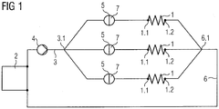
- FIG. 1 shows a schematic representation of the circulation system according to the invention, in which a reservoir 2, in which a nutrient solution is contained, via a branching micro-channel structure 3 is connected to at least one input 1.1 more cell culture compartments 1.
- a conveyor 4 in the form of a peristaltic pump for conveying the nutrient solution is arranged.
- a respective device for controlling the volume flow 5 is arranged in each arm or in each microchannel, which connects the first-order branch point 3.1 and the inputs 1.1 of the cell culture compartments 1 to one another.
- Each of the devices for controlling the volume flow 5 has a connection to a second microchannel structure 7.
- Each output 1.2 of the cell culture compartments 1 is connected via a microchannel to a mouth point 6.1 of a third microchannel structure 6, which opens into the reservoir 2.
- the devices for volume flow control 5, which are each connected to a separate microchannel of a second microchannel structure 7, each realized with a diaphragm valve having a flexible membrane, which is formed as a partition between a microchannel of the first microchannel structure 3 and the microchannel structure 7 is.
- the devices for controlling the volume flow 5 can be acted upon by a pneumatic and / or hydraulic pressure, so that a curvature of the flexible membrane dependent on this pressure causes a cross-sectional constriction of the respective microchannel of the first microchannel structure 3, so that the respectively into the cell culture - Kompartimente 1 supplyable volume flow of the funded from the reservoir 2 nutrient solution is reduced.
- FIG. 2a shows a sectional view of a realized with a diaphragm valve means for flow control 5.
- the diaphragm valve has a flexible membrane 5.1.
- Reference numeral 3 denotes the first microchannel structure 3 or a microchannel of the first microchannel structure 3, the horizontal arrows indicating the flow direction of the nutrient solution.
- the flexible membrane 5.1 is curved in the direction of the first microchannel as a result of a pneumatic pressurization on the second microchannel structure 7, so that the cross-sectional area of the first microchannel 3 that can be flowed through by the nutrient solution is narrowed.
- the flexible membrane 5.1 is a selectively permeable membrane formed of PDMS, which is permeable to oxygen. Because the second microchannel structure 7 in the present example has a higher oxygen partial pressure compared to the first microchannel structure 3, oxygen can be released from the second microchannel structure 7 into the first microchannel 3, so that the nutrient solution flowing therein can be enriched with oxygen.
- the reference numeral 8 shows the laser beam of a laser interferometer, which is directed to the flexible membrane 5.1, so that the curvature / elongation of the flexible membrane 5.1 can be determined. The same optical access allows the detection of the oxygen partial pressure, for example by fluorescence lifetime measurement on immobilized particles.
- FIG. 2b shows a further embodiment of the device for volume flow control 5, which is also realized with a diaphragm valve having a flexible membrane 5.1.
- a change in the cross section of the first microchannel 3 is realized by applying a negative pressure (pneumatic) to the second microchannel structure 7.
- While this embodiment of the device for controlling the volume flow 5 locks the volume flow through the first microchannel structure 3 or through a microchannel of the first microchannel structure 3 when an overpressure or contact of a normal pressure, which is equal to the pressure in the first microchannel structure 3, intervenes a negative pressure at the second microchannel structure 7 a Achieved curvature in the direction of the second micro-channel structure 7 and thereby extends the cross section of the first micro-channel structure 3.
- the oxygen partial pressure within the microchannel structure 7 is lower than the first microchannel structure 3, so that oxygen is withdrawn from the nutrient solution when the nutrient solution flows past the membrane 5.1.
- FIG. 3a shows a schematic sectional view of an embodiment of the device for controlling the flow rate 5, in which the flexible membrane 5.1 and the second micro-channel structure 7 are formed from a PDMS casting.
- the first microchannel structure 3 or a microchannel of the microchannel structure 3, in which the nutrient solution flows, is formed between a glass plate (glass lid) and the casting.
- FIG. 3b shows a further advantageous embodiment of the device for controlling the volume flow 5 in a multi-layer structure of the circulation system according to the invention in the form of a schematic sectional view.
- the individual layers 5.1, 5.2, 5.3 and 5.4 are preferably formed from PC - but can also be formed from PDMS, PP or PET, wherein for each layer and different polymer materials can be used.
- the individual layers have corresponding structures or recesses corresponding to a structure to be formed (conveying device, microchannel structure, reservoir, cell culture compartment) and are laminated on top of one another.
- the flexible membrane 5.1 is represented by a PDMS layer, which forms a dividing wall between the second microchannel structure 7 formed in the first layer 5.2 and the first microchannel structure 3, which is formed in the layer 5.3.
- Reference numeral 5.4 denotes the lower layer, which terminates the microchannel structure 3 in a fluid-tight manner.
- the layer 5.2 may also be formed a fluid-tight final layer.
Landscapes
- Health & Medical Sciences (AREA)
- Chemical & Material Sciences (AREA)
- Life Sciences & Earth Sciences (AREA)
- Organic Chemistry (AREA)
- Wood Science & Technology (AREA)
- Engineering & Computer Science (AREA)
- Bioinformatics & Cheminformatics (AREA)
- Zoology (AREA)
- General Engineering & Computer Science (AREA)
- Biotechnology (AREA)
- Microbiology (AREA)
- Biochemistry (AREA)
- Biomedical Technology (AREA)
- General Health & Medical Sciences (AREA)
- Genetics & Genomics (AREA)
- Sustainable Development (AREA)
- Clinical Laboratory Science (AREA)
- Immunology (AREA)
- Analytical Chemistry (AREA)
- Dispersion Chemistry (AREA)
- Molecular Biology (AREA)
- Apparatus Associated With Microorganisms And Enzymes (AREA)
Description
- Die vorliegende Erfindung betrifft den Bereich mikrofluidischer Zellkultursysteme, insbesondere ein Zirkulationssystem sowie ein Verfahren zur Vitalversorgung solcher Zellkulturen.
- Zum Prüfen und Testen von Arzneimitteln, Chemikalien oder Kosmetika, sowie bei der Suche nach Wirkstoffen oder deren Wirkung hervorrufende Signalwege werden klassische Tierversuche mehr und mehr durch Bioassays verdrängt. Nicht zuletzt aus ethischen als auch ökonomischen Gründen werden daher Zellkultursysteme gefordert, mit denen aussagekräftige Daten gewonnen werden können, die vergleichbar sowie reproduzierbar sind. Die Bestrebungen führen daher zu Zellkultursystemen, mit denen artgleiche Zelltypen bzw. unterschiedliche Zelltypen eines Individuums oder Organismus in geschlossenen Kreisläufen kultiviert werden können. Zur Nachahmung metabolischer Prozesse werden dabei verschiedene Zelltypen, wie beispielsweise Cardiozyten, Hepatozyten, Osteozyten oder Zellen weiterer, bspw. neuronaler (afferente oder efferente) Gewebe, in Kompartimenten räumlich voneinander getrennt, in mikrofluidischen Netzwerken mit Nährstoffen versorgt und begast. Vorwiegend gestaltet sich die Kultivierung solcher komplexen Bioassays jedoch dadurch problematisch, dass für die einzelnen verschiedenen Zelltypen unterschiedliche Kulturbedingungen erforderlich sind.
-
EP 2 505 638 A1 offenbart ein aus neuronalen und somatischen Zellen gebildetes Bioassay. Zur Ausbildung eines neuronalen Affektor-Effektor-Netzwerks sind die verschiedenen Zelltypen dabei in einem fluidischen Kreislauf nacheinander, d.h. in Reihe in entsprechenden Kavitäten angeordnet. Zur Inkubation der verschiedenen Zelltypen werden die Kavitäten vorzugsweise vom gemeinsamen fluidischen Kreislauf getrennt. Infolge der Reihenanordnung der einzelnen Kavitäten bzw. Kompartimente wird dabei auch der Fluidkreislauf der gemeinsamen Vitalversorgung vollständig unterbrochen, so dass die einzelnen Zellkulturen außerhalb des Netzwerks aufwendig separat stimuliert und versorgt werden müssen. Nachteilig ist weiterhin, dass die jeweiligen Zellen enthaltenden Kavitäten innerhalb der fluidischen Reihenanordnung einem gemeinsamen Volumenstrom und somit einem gemeinsamen hydraulischen Druck ausgesetzt sind. Dies kann sich jedoch negativ auf die unterschiedlichen Bedürfnisse der verschiedenen Zelltypen auswirken und somit die Adhärenz, Differenzierung und Proliferation der zuvor aufwendig inkubierten Zelltypen negativ beeinflussen. Um optimale Bedingungen zur Ausdifferenzierung und Proliferation spezieller Zelltypen insbesondere in geschlossenen Kreisläufen bereitzustellen ist es daher erforderlich, für möglichst jedes Kompartiment differenzierte Kulturbedingungen mit möglichst großer nähe zu natürlichen (physiologischen) Bedingungen zu gewährleisten. - Aus
WO 2012/016711 A1 ist ein geschlossenes Zirkulationssystem sich aufzweigender Kapillaren zur Bildung und Versorgung biologischer Gewebsstrukturen bekannt. Mittels einer Pumpe wird dabei ein physiologisches Fluid pulsierend durch einen arteriell strukturierten bzw. sich aufzweigenden Teil eines Kreislaufs gepumpt, der in einem Zellkulturen enthaltenden Kompartiment mündet, wobei venöses Fluid aus dem Zellkulturkompartiment in einen venös strukturierten Teil mündet. Der arterielle- und der venöse Teil bilden dabei einen geschlossen Kreislauf. Schwankungen des Drucks und des Volumenstroms innerhalb dieses Kreislaufs sollen dadurch verhindert werden, dass der Volumenstrom an einem arteriellen Verzweigungspunkt jeweils zu gleichen Teilen aufgeteilt in einem venösen Mündungspunkt zu gleichen Teilen wieder zusammengeführt wird. Durch entsprechend dimensionierte Querschnitte von Mikrokanälen wird eine definierte Strömungsaufteilung erreicht. Es ist also davon auszugehen, dass der effektive Volumenstrom im Kreislauf konstant ist, so dass auch die parallel angeordneten Zellkulturkompartimente mit einem konstanten Volumenstrom versorgt werden. - Für solche Zellkultursysteme, bei denen mehrere Zellkulturkompartimente mit unterschiedlichen Zellkulturen aus einem zentralen geschlossenen Fluidkreislauf versorgt werden ist es jedoch erforderlich, die Volumenströme und Drücke innerhalb des Kreislaufs an die jeweiligen Bedürfnisse der verschiedenen Zelltypen anzupassen, um eine optimale Adhärenz, Differenzierung und/oder Proliferation von allen in diesem geschlossenen System vorhandenen Zellkulturnen zu erreichen. Neben hydraulischen Stimuli wie statische und dynamische Druckbeaufschlagung sollten auch weitere physiologische Parameter, wie beispielsweise pH-Wert, Gassättigung (Sauerstoffpartialdruck, Kohlendioxidpartialdruck) oder Glukose-Konzentration möglichst vor unmittelbarem Kontakt mit den Zellkulturen geregelt werden können.
- So sind aus
WO 03/085379 A2 DE 10 2006 030 068 A1 eine Vorrichtung und ein Verfahren zur Zu- und Abfuhr von Fluiden in geschüttelten Mikrireaktoren Arrays und ausUS 2006/0199260 A1 ein mikrobiologischer Reaktor für eine kontinuierliche Zellkultivierung bekannt. -
WO 2007/047772 A2 betrifft eine mikrofluidische Zellkultivierungsvorrichtung. - Ein Verfahren zur Herstellung eines Biorektors oder Lab-on-Chip-Systems sowie damit hergestellte Bioreaktoren oder Lab-on-Chip-Systemen sind in
WO 2008/025351 A2 und eine Vorrichtung und ein Verfahren für pharmakinetische Basiszellkultursysteme inWO 03/027223 A2 - Die Offenbarung von
WO 2012/016711 A1 betrifft ein Zirkulationssystem. - Es ist daher Aufgabe der vorliegenden Erfindung, eine Vorrichtung und ein Verfahren zur Vitalversorgung von Zellkulturen in einem Zellkultursystem bereitzustellen, wobei eine separate definierte Versorgung einzelner Zellkulturen möglich ist.
- Die Aufgabe wird mit einem Zirkulationssystem nach Anspruch 1 und aus verfahrenstechnischer Sicht nach Anspruch 12 gelöst. Vorteilhafte Ausgestaltungen der vorliegenden Erfindung können mit Merkmalen der untergeordneten Ansprüche erreicht werden.
- Erfindungsgemäß wird zur Vitalversorgung von Zellkulturen in einem mikrofluidischen Netzwerk ein Zirkulationssystem vorgeschlagen, das mehrere Zellkultur-Kompartimente enthält, die jeweils mindestens einen Eingang und mindestens einen Ausgang aufweisen. Weiterhin weist das Zirkulationssystem mindestens ein Nährlösung enthaltendes Reservoir auf, das über eine erste Mikrokanalstruktur, die zumindest eine Verzweigung erster Ordnung aufweist, mit mindestens einem Eingang jedes Zellkultur-Kompartiments verbunden ist. Außerdem ist mindestens eine Fördereinrichtung enthalten, mit der die Nährlösung aus dem Reservoir über die Mikrokanalstruktur in die Zellkultur Kompartimente förderbar ist. Erfindungsgemäß ist das Zirkulationssystem dadurch gekennzeichnet, dass in jedem Arm der Verzeigung erster Ordnung und/oder im Verlauf jedes unmittelbar in einen Eingang eines Zellkultur-Kompartiments mündenden Mikrokanals der ersten Mikrokanalstruktur eine Einrichtung zur Volumenstromregelung angeordnet ist, mit der ein Volumenstrom der Nährlösung regelbar ist.
- Gegenüber dem Stand der Technik liegt der Kern der vorliegenden Erfindung daher in der Möglichkeit, dass der Volumenstrom einer Nährlösung, die aus einem zentralen Reservoir durch ein sich verzweigendes mikrofluidischen Netzwerk förderbar ist bzw. gefördert wird, unmittelbar vor dem Einlass in jedes Zellen enthaltende Kompartiment regelbar ist. Vorteilhafterweise kann der Volumenstrom der Nährlösung und weiterer Fluide dabei in Abhängigkeit des Nährstoffbedarfs jedes einzelnen Kompartiments geregelt werden. Als Kompartimente sollen vorzugsweise zylindrische oder sphärische Räume verstanden werden, in denen Bedingungen und Möglichkeiten zur Adhärenz von Zellen gegeben sind. Ein Kompartiment kann daher eine entsprechende Oberflächenbeschaffenheit bzw. eine Beschichtung aufweisen. In einem Kompartiment können aber auch Kollagen-Strukturen (scaffolds) enthalten sein, die eine dreidimensionale Proliferation von Zellen ermöglichen. Es kann sich bei den Kompartimenten allerdings auch um Kavitäten handeln, in denen flüssige Zellkulturen enthalten sind.
- Vorzugsweise sind die Zellkultur-Kompartimente in dem Zirkulationssystem (analog elektrotechnischer Anordnungen) parallel zueinander angeordnet, wobei im Anschluss an eine Verzweigung erster Ordnung, d.h. an einem Arm der Verzweigung bzw. im Verlauf der sich verzweigenden ersten Mikrokanalstruktur, auch mehrere der Zellkultur-Kompartimente in Reihe angeordnet sein können und/oder zumindest durch eine Mikrokanalverbindung zwischen mindestens einem Ausgang eines ersten Zellkultur-Kompartiments mit mindestens einem Eingang eines weiteren Zellkultur-Kompartiments verbunden sein. Dabei kann die Einrichtung zur Volumenstromregelung auch im Verlauf einer Mikrokanalverbindung der ersten Mikrokanalstruktur angeordnet sein, die mindestens zwei Zellkultur-Kompartimente in Reihe miteinander verbindet.
- Wie bereits beschrieben, weist die erste Mikrokanalstruktur mindestens eine Verzweigung erster Ordnung auf, wobei darunter zu verstehen ist, dass sich die Mikrokanalstruktur zumindest einmal in mindestens zwei Mikrokanäle verzweigt. Dabei kann die Verzweigung erster Ordnung eine Mehrzahl von Armen aufweisen, die vorzugsweise jeweils unmittelbar in einen Eingang eines Zellkultur-Kompartiments münden.
- In einer vorteilhaften Ausführungsform kann die erste Mikrokanalstruktur im Verlauf mindestens eines Arms der Verzweigung erster Ordnung mindestens eine weitere Verzweigung zweiter Ordnung aufweisen, die ebenfalls mehrere Arme aufweisen kann, von denen jeder Arm mit mindestens einem Eingang eines Zellkultur-Kompartiments verbunden ist.
- Bei einer weiteren vorteilhaften Ausführungsform des erfindungsgemäßen Zirkulationssystems kann mindestens ein Arm einer Verzweigung zweiter Ordnung mindestens eine weitere Verzweigung dritter Ordnung aufweisen, deren Arme jeweils in mindestens einen Eingang eines Zellkulturkompartiments münden.
- Denkbar ist weiterhin, dass mehrere Arme einer Verzweigung erster, zweiter und/oder dritter Ordnung in mehrere Eingänge eines Zellkultur-Kompartiments münden, wobei im Verlauf aller unmittelbar in ein Zellkultur-Kompartiment mündenden Arme, d.h. Mikrokanälen der ersten Mikrokanalstruktur - durch die die Nährlösung in das Zellkultur-Kompartiment gefördert wird - eine Einrichtung zur Volumenstromregelung vorhanden ist.
- Das gesamte Zirkulationssystem kann im Mehrschichtaufbau realisiert sein, wobei mehrere Schichten miteinander laminierbar und flächig stoffschlüssig mit einander verbunden sind und in mindestens einer Schicht entsprechende Aussparungen für Mikrokanalstrukturen, für mindestens ein Reservoir, mindestens eine Fördereinrichtung, Zellkultur-Kompartimente und Einrichtungen zur Volumenstromregelung ausgebildet sind. Die Aussparungen der übereinander angeordneten Schichten bilden dabei Zwischenräume der genannten Strukturen aus, die in einem Netzwerk miteinander korrespondieren. Somit können mehrere dreidimensionale Mikrokanalstrukturen auf engstem Raum mit entsprechenden Zellkultur-Kompartimenten realisiert sein. Die einzelnen Schichten können beispielsweise aus Polydimethylsiloxan (PDMS), Polycarbonant (PC), Polypropylen (PP) oder Polyethylenterephthalat (PET) gebildet sein.
- Unter Mikrokanälen sollen solche Kanäle verstanden werden, deren Durchmesser 1 mm oder durchströmbare Querschnittsfläche von 1 mm2 nicht übersteigt.
- Mikrokanäle erster, zweiter und dritter Ordnung sollten eine maximale Länge von 1 mm bis 100 mm aufweisen.
- Die Volumina der Zellkulturkompartimente können im Bereich von 1 mm3 bis 100 mm3 variieren.
- Die Einrichtung(en) zur Volumenstromregelung kann/können mit einer zweiten Mikrokanalstruktur verbunden sein, über die mindestens ein Fluid und/oder mindestens eine Substanz in einen Mikrokanal der ersten Mikrokanalstruktur in dosierter Form zuführbar ist/sind. Hierzu kann/können die Einrichtung(en) zur Volumenstromregelung mit einem MEMS(micro-electromechanical-system)-basierten Mikroventil realisiert sein, das die dosierte Abgabe aus der zweiten Mikrokanalstruktur in die erste Mikrokanalstruktur gewährleistet.
- Entsprechend kann/können die Einrichtung(en) zur Volumenstromregelung auch mit einem magentischen, elektromagnetischen, elektromotorischen pneumatischen, elektropneumatischen, hydraulischen oder elektrohydraulischen Ventil (Mikroventil) realisiert sein. Die Einrichtung(en) zur Volumenstromregelung ist/sind_mit einem Membranventil realisiert, das eine flexiblen Membran aufweist. Dadurch kann das Ventil mit einem von außen aufgebrachten pneumatischen oder hydraulischen Druck betätigt werden.
- Vorteilhafterweise kann die flexible Membran als Trennwand zwischen der ersten Mikrokanalstruktur und der zweiten Mikrokanalstruktur ausgebildet sein, wobei die flexible Membran über die zweite Mikrokanalstruktur mit einem aktivierbaren/deaktivierbaren vorgebbaren pneumatischen und/oder vorgebbaren hydraulischen Druck beaufschlagbar ist. Bei einer druckabhängigen (pneumatischen oder hydraulischen) Wölbung/Dehnung der flexiblen Membran kann eine Änderung der von der Nährlösung durchströmbaren Querschnittsfläche eines Mikrokanals der ersten Mikrokanalstruktur erreicht werden. Mit entsprechenden Mitteln kann ein Mikrokanal der zweiten Mikrokanalstruktur daher so mit Überdruck beaufschlagt werden, dass eine in den Mikrokanal der ersten Mikrokanalstruktur hineinragende definierte Wölbung der flexiblen Membran erreicht werden kann, die eine definierte Querschnittsverengung des entsprechenden Mikrokanals der ersten Mikrokanalstruktur hervorruft. Infolge der Variation der von der Nährlösung durchströmbaren Querschnittsfläche, kann der Volumenstrom der Nährlösung in dem entsprechenden Mikrokanal eingestellt werden.
- Es ist anzumerken, dass jede Einrichtung zur Volumenstromregelung unabhängig von weiteren in dem Netzwerk vorhandenen Einrichtungen zur Volumenstromregelung betrieben werden kann. Eine zweite Mikrokanalstruktur ist daher jeweils nur mit einer einzigen Einrichtung zur Volumenstromregelung verbunden, so dass die Anzahl der zweiten Mikrokanalstrukturen mit der Anzahl der Einrichtungen zur Volumenstromregelung übereinstimmen. Bei einer vorteilhaften Ausführungsform können jedoch auch sich verzweigende zweite Mikrokanalstrukturen eingesetzt werden, wobei eine zweite Mikrokanalstruktur mit mehreren Einrichtungen zur Volumenstromregelung verbunden sind. In diesem Fall können dann Gruppen von Einrichtungen zur Volumenstromregelung unabhängig voneinander betrieben werden.
- Eine definierte Wölbung der flexiblen Membran kann auch durch einen an der zweiten Mikrokanalstruktur aufgebrachten Unterdruck erreicht werden, wobei die Wölbung in den Mikroanal der zweiten Mikrokanalstruktur hineinragt. In diesem Fall kann der erste Mikrokanal, durch den die Nährlösung gefördert wird, so ausgestaltet sein, dass der Durchfluss bei Normaldruck (es liegt kein Über- bzw. Unterdruck an der zweiten Mikrokanalstruktur an) durch die flexible Membran gesperrt ist. Erst bei Anliegen eines Unterdrucks an der zweiten Mikrokanalstruktur wird die flexible Membran so definiert gewölbt, dass in dem ersten Mikrokanal eine definierte durchströmbare Querschnittsfläche erreicht wird, durch die der Volumenstrom der Nährlösung verändert wird.
- Es ist weiterhin besonders vorteilhaft, wenn die flexible Membran aus einem selektivpermeablen Material gebildet ist, das für mindestens ein Fluid, vorzugsweise ausgewählt aus der Gruppe aus Stickstoff, Sauerstoff, Kohlendioxid und/oder mindestens eine Substanz, vorzugsweise ausgewählt aus der Gruppe aus Stickstoff, Phosphat, Glucose, HSA (numanes Serumalbumin), Wachstumsfaktoren, wie EGF (endothelial growth factor), VEGF (vascular endothelial growth factor) oder NGF (nerve growth factor) permeabel ist, so dass ein Austausch des mindestens einen Fluids und/oder der mindestens einen Substanz zwischen einem Kanal der ersten Mikrokanalstruktur und der zweiten Mikrokanalanalstruktur realisierbar ist. Als Fluid werden dabei Flüssigkeiten als auch Gase verstanden. Die selektivpermeable Membran kann aber auch als Port zum Austausch von niedermolekularen Testsubstanzen, wie beispielsweise Medikamenten dienen, deren Einfluss auf ein jeweiliges Zellkultur-Kompartiment bzw. den darin kultivierten Zellen getestet werden soll.
- Durch die selektivpermeable Eigenschaft der flexiblen Membran können die Einrichtungen zur Volumenstromregelung zusätzlich auch als individuelle Dosierer für die einzelnen Zellkultur-Kompartimente eingesetzt werden, wobei individuelle Bedürfnisse der verschiedenen Zellkulturen berücksichtigt werden können. Dabei ist ein Substanz- und/oder Fluid-Austausch in beide Richtungen oder nur in eine Richtung durch die Membran möglich. So kann beispielsweise eine Erhöhung des Sauerstoffpartialdrucks einer in dem ersten Mikrokanal strömenden Nährlösung dadurch erreicht werden, dass die zweite Mikrokanalstruktur mit einem erhöhten Sauerstoffpartialdruck beaufschlagt wird, wobei Sauerstoff durch die für Sauerstoff permeable flexible Membran in den ersten Mikrokanal und somit in die Nährlösung gelangt. Gleichzeitig kann im ersten Mikrokanal der Volumenstrom der Nährlösung durch die Wölbung der flexiblen Membran verändert werden. Es kann auch eine Senkung des Sauerstoffpartialdrucks erreicht werden, in dem der zweite Mikrokanal mit geringem Sauerstoffpartialdruck beaufschlagt wird, wobei der Nährlösung beim Vorbeiströmen an der flexiblen Membran Sauerstoff entzogen wird. Dabei sollte am zweiten Mikrokanal möglichst Unterdruck anliegen. Die Einrichtungen zur Volumenstromregelung können den Einsatz von Oxygenatoren/Deoxygenatoren somit vollständig ersetzten.
- Die selektivpermeable flexible Membran kann aus einem Kunststoffmaterial, wie beispielsweise Polydimethylsiloxan (PDMS), Polycarbonant (PC), Polypropylen (PP) oder Polyethylenterephthalat (PET) gebildet sein und auf einer der Nährlösung zugewandten Seite, eine amphiphile Oberflächenbeschichtung aufweisen, so dass eine möglichst geringe Adhäsion von in der Nährlösung enthaltenden Substanzen und/oder ausgeschwemmten Zellen erreicht werden kann.
- Der Volumenstrom bzw. die Durchströmung durch die einzelnen Kanäle der Mikrokanalstruktur kann entweder direkt durch berührungslose Strömungsmesstechnik, wie z.B. Particle Image Velocimetry (PIV) oder via Laser-Doppler Anemometrie (LDA) erfasst werden. Der Druck im Mikrokanal kann durch Wölbung an einer dafür vorgesehenen Messmembran oder an der flexiblen selektivpermeablen Membran erfasst werden. Weiterhin können die Einrichtungen zur Volumenstromregelung sensorische Mittel aufweisen, mit denen die Wölbung/Dehnung der flexiblen Membran sowie Drücke, Partialdrücke und/oder Volumenströme der Nährlösung vorzugsweise berührungslos erfasst werden können. Die Wölbung kann beispielsweise optisch, mit konfokalen Sensoren und/oder einem Laser-Interferometer erfasst werden, die in den Einrichtungen zur Volumenstromregelung vorgesehen sind. Mit weiteren optischen Messverfahren, wie z.B. Verfahren zur Bestimmung der Fluoreszenzlebensdauer oder SPR (surface plasmon resonance) können auch Fluide und/oder Konzentrationen von Fluiden und/oder Substanzen erfasst werden, die in der Nährlösung enthalten sind und/oder in dosierter Form zugeführt werden. Anhand der mit den genannten Sensoren erfassten Messwerte können die pneumatischen und/oder hydraulischen Drücke, die zur Wölbung der flexiblen Membran auf die zweite Mikrokanalstruktur beaufschlagt werden, so eingestellt werden, dass eine definierte Volumenströmung der Nährlösung erreicht werden kann. Neben den berührungslosen Sensoren können auch elektrochemische Sensoren oder Sensoren eingesetzt werden, die auf leitfähigen Materialien beruhen.
- Auch das Dosieren von Fluiden und/oder Substanzen kann anhand der mit den Sensoren erfassten Messwerte geregelt werden. Hierzu kann die zweite Mikrokanalstruktur jeweils mit einem entsprechenden Fluid(Gas)-Mischer oder Substanzmischer verbunden sein.
- Entsprechend eines geschlossenen Kreislaufs des erfindungsgemäßen Zirkulationssystems, weist jedes in dem Zirkulationssystem vorhandene Zellkultur-Kompartiment mindestens einen Ausgang auf, der über eine Mikrokanalverbindung mit mindestens einem Mündungspunkt einer dritten Mikrokanalstruktur verbunden ist, die in das Nährlösung enthaltende Reservoir mündet.
- Vorzugsweise sind die erste Mikrokanalstruktur und die dritte Mikrokanalstruktur spiegelbildlich ausgebildet
- Selbstverständlich können die Einrichtungen zur Volumenstromregelung auch im Verlauf jeder Mikrokanalverbindungen angeordnet sein, die einen Ausgang eines Zellkultur-Kompartiments mit einem Mündungspunkt der dritten Mikrokanalstruktur verbindet.
- Bei einer vorteilhaften Ausführungsform des erfindungsgemäßen Zirkulationssystems kann im Verlauf der ersten Mikrokanalstruktur vor der mindestens einen Verzweigung erster Ordnung und/oder in jedem Arm der Verzeigung erster Ordnung und/oder im Verlauf jedes unmittelbar in einen Eingang der Zellkultur-Kompartimente mündenden Mikrokanals der ersten Mikrokanalstruktur, mindestens ein erster Oxygenator/Deoxygenator und/oder im Verlauf jeder aus einem Ausgang eines Zellkultur-Kompartiments in eine dritte Mikrokanalstruktur führende Mikrokanalverbindung vor einem Mündungspunkt und/oder dahinter im Verlauf der dritten Mikrokanalstruktur ein zweiter Oxygenator/Deoxygenator angeordnet sein. Auf diese Weise können im Verlauf der ersten Mikrokanalstruktur über ein Zellkultur-Kompartiment bis zur dritten Mikrokanalstruktur, unabhängig vom Volumenstrom der Nährlösung, definierte Gradienten von Sauerstoff-, Kohlendioxid und/oder Stickstoffpartialdrücken erreicht werden.
- Zur Bereitstellung des Förderstroms der Nährlösung kann als Fördereinrichtung eine Peristaltikpumpe eingesetzt werden, die vorzugsweise vor einer Verzweigung erster Ordnung im Verlauf der ersten Mikrokanalstruktur angeordnet ist.
- Bei dem erfindungsgemäßen Verfahren zur Vitalversorgung von Zellkulturen in einem mikrofluidischen Netzwerk, wird eine Nährlösung mit einer Fördereinrichtung aus einem Reservoir über mindestens eine Verzweigung erster Ordnung einer sich verzweigenden Mikrokanalstruktur eingangsseitig in mehrere Zellkultur-Kompartimente gefördert, wobei der Volumenstrom der Nährlösung in jedem Arm der Verzeigung erster Ordnung und/oder im Verlauf jedes unmittelbar in einen Eingang eines Zellkultur-Kompartiments mündenden Mikrokanals der Mikrokanalstruktur separat geregelt wird.
- Bei dem erfindungsgemäßen Verfahren wird eine Einrichtung zur Volumenstromregelung eingesetzt, die ein Membranventil mit einer flexiblen Membran enthält, wobei die flexible Membran als Trennwand zwischen der ersten Mikrokanalstruktur und einer zweiten Mikrokanalstruktur ausgebildet ist. Wird über die zweite Mikrokanalstruktur ein aktivierbarer/deaktivierbarer vorgebbarer pneumatischer und/oder vorgebbarer hydraulischer Druck beaufschlagt, kann die flexible Membran derart gewölbt/gedehnt werden, dass die von der Nährlösung durchströmbare Querschnittsfläche des Mikrokanals der ersten Mikrokanalstruktur verändert wird.
- Vorteilhafterweise kann als flexible Membran eine aus PDMS, Polycarbonant (PC), Polypropylen (PP) oder Polyethylenterephthalat (PET) gebildete selektivpermeable Membran verwendet werden, über die zwischen einem Mikrokanal der ersten Mikrokanalstruktur und der zweiten Mikrokanalanalstruktur bzw. einem Mikrokanal der zweiten Mikrokanalstruktur mindestens ein Fluid, vorzugsweise ausgewählt aus der Gruppe aus Stickstoff, Sauerstoff, Kohlendioxid und/oder mindestens eine Substanz, vorzugsweise ausgewählt aus der Gruppe aus Phosphat, Glucose, HSA oder EGF ausgetauscht und/oder dosiert wird. Selbstverständlich kann die selektivpermeable Membran auch so ausgebildet sein, dass sie zum Austausch nur einer Testsubstanz, wie z.B. niedermolekularen Strukturen geeignet ist. Bei solchen niedermolekularen Strukturen kann es sich vorzugsweise um Wirkstoffe oder Medikamente handeln, deren Einfluss auf Zellkultur-Kompartimente bzw. auf die darin kultivierten Zellen getestet werden sollen.
- Zur Regelung der Volumenströmung der Nährlösung werden die Wölbung/Dehnung der flexiblen Membran sowie Drücke, Partialdrücke und/oder Volumenströme der Nährlösung mit berührungslosen optischen Sensoren erfasst. Die Wölbung wird mit konfokalen Sensoren und/oder einem Laser-Interferometer erfasst, wobei der Volumenstrom bzw. die Durchströmung auch direkt mit PIV oder LDA detektiert werden kann. Mit weiteren Sensoren oder Messverfahren, wie z.B. Verfahren und Sensoren zur Erfassung von Fluoreszenz bzw. Fluoreszenzlöschung sowie SPR-Methoden können auch in der Nährlösung enthaltene oder zugeführte Fluide und/oder Konzentrationen von Fluiden und/oder Substanzen erfasst werden.
- Die Volumenstromregelung in den Mikrokanälen wird also so realisiert, dass zunächst ein Volumenstrom-Ist-Wert der geförderten Nährlösung mit Hilfe einer der optischen Sensoren der Einrichtung zur Volumenflussregelung erfasst wird. Anschließend wird die zweite Mikrokanalstruktur bzw. ein Mikrokanal der Mikrokanalstruktur mit einem definierten pneumatischen bzw. hydraulischen Druck beaufschlagt, bis eine Wölbung der flexiblen Membran erreicht ist, die eine Verengung des von der Nährlösung durchströmbaren Querschnitts verursacht und den Volumenstrom der Nährlösung dadurch begrenzt.
- Weiterhin können Ist-Werte zu regelnder bzw. zu dosierender Substanzen oder Vitalparameter (Sauerstoffsättigung, LDH (Lactatdehydrogenase), NADH (Nicotinamidadenindinukleotid)) erfasst werden und anschließend durch die beschriebene Volumenstromregelung auf Basis eines Massentransportmodels auf einen vorgebbaren Soll-Wert eingestellt werden. Vorteilhafterweise kann dadurch eine bedarfsgerechte Nährstoffzugabe und eine gezielte Beaufschlagung mit Testsubstanzen erreicht werden.
- Nachfolgend wird die vorliegende Erfindung anhand von Ausführungsbeispielen und Figuren näher erläutert. Es zeigen:
-
Figur 1 : eine schematische Darstellung eines Ausführungsbeispiels des erfindungsgemäßen Zirkulationssystems -
Figur 2a /b: schematische Schnittdarstellungen einer Einrichtung zur Volumenstromregelung im Über- und Unterdruckbetrieb -
Figur 3a /b: schematische Schnittdarstellungen der Einrichtung zur Volumenstromregelung in gegossener Ausführung a) und als Mehrschicht-Ausführung b) - Die
Figur 1 zeigt eine schematische Darstellung des erfindungsgemäßen Zirkulationssystems, bei dem ein Reservoir 2, in dem eine Nährlösung enthalten ist, über eine sich aufzweigende Mikrokanalstruktur 3 mit jeweils mindestens einem Eingang 1.1 mehrerer Zellkultur-Kompartimente 1 verbunden ist. Im Verlauf der ersten Mikrokanalstruktur 3 ist eine Fördereinrichtung 4 in Form einer Peristaltikpumpe zur Förderung der Nährlösung angeordnet. In jedem Arm bzw. in jedem Mikrokanal, der den Verzweigungspunkt erster Ordnung 3.1 und die Eingänge 1.1 der Zellkultur-Kompartimente 1 miteinander verbindet, ist jeweils eine Einrichtung zur Volumenstromregelung 5 angeordnet. Jede der Einrichtungen zur Volumenstromregelung 5 weist dabei eine Verbindung mit einer zweiten Mikrokanalstruktur 7 auf. Jeweils jeder Ausgang 1.2 der Zellkultur-Kompartimente 1 ist über einen Mikrokanal mit einem Mündungspunkt 6.1 einer dritten Mikrokanalstruktur 6 verbunden, die in das Reservoir 2 mündet. - Im vorliegenden Beispiel sind die Einrichtungen zur Volumenstromregelung 5, die jeweils mit einem separaten Mikrokanal einer zweiten Mikrokanalstruktur 7 verbunden sind, jeweils mit einem Membranventil realisiert, das eine flexible Membran aufweist, die als Trennwand zwischen einem Mikrokanal der ersten Mikrokanalstruktur 3 und der Mikrokanalstruktur 7 ausgebildet ist. Über die zweite Mikrokanalstruktur 7 sind die Einrichtungen zur Volumenstromregelung 5 mit einem pneumatischen und/oder hydraulischen Druck beaufschlagbar, so dass eine von diesem Druck abhängige Wölbung der flexiblen Membran eine Querschnittsverengung des jeweiligen Mikrokanals der ersten Mikrokanalstruktur 3 verursacht, so dass der jeweils in die Zellkultur-Kompartimente 1 zuführbare Volumenstrom der aus dem Reservoir 2 geförderten Nährlösung verringert wird.
- Die
Figur 2a zeigt eine Schnittdarstellung einer mit einem Membranventil realisierten Einrichtung zur Volumenstromregelung 5. Dabei weist das Membranventil eine flexible Membran 5.1 auf. Das Bezugszeichen 3 kennzeichnet die erste Mikrokanalstruktur 3 bzw. einen Mikrokanal der ersten Mikrokanalstruktur 3, wobei die horizontalen Pfeile die Flussrichtung der Nährlösung anzeigen. Im vorliegenden Beispiel ist die flexible Membran 5.1 in Folge einer pneumatischen Druckbeaufschlagung auf die zweite Mikrokanalstruktur 7 in Richtung des ersten Mikrokanals gewölbt, so dass die von der Nährlösung durchströmbare Querschnittsfläche des ersten Mikrokanals 3 verengt ist. Bei der flexiblen Membran 5.1 handelt es sich im vorliegenden Beispiel um eine aus PDMS gebildete selektivpermeable Membran, die für Sauerstoff permeabel ist. Dadurch, dass die zweite Mikrokanalstruktur 7 im vorliegenden Beispiel gegenüber der ersten Mikrokanalstruktur 3 einen höheren Sauerstoffpartialdruck aufweist, kann Sauerstoff aus der zweiten Mikrokanalstruktur 7 in die ersten Mikrokanal 3 abgegeben werden, so dass die darin strömende Nährlösung mit Sauerstoff angereichert werden kann. Mit dem Bezugszeichen 8 ist der Laserstrahl eines Laser-Interferometers dargestellt, der auf die flexible Membran 5.1 gerichtet ist, so dass die Wölbung/Dehnung der flexiblen Membran 5.1 bestimmt werden kann. Der gleiche optische Zugang ermöglicht die Detektion des Sauerstoffpartialdrucks, beispielsweise durch Fluoreszenzlebensdauermessung an immobilisierten Partikeln. - Die
Figur 2b zeigt ein weiteres Ausführungsbeispiel der Einrichtung zur Volumenstromregelung 5, die ebenfalls mit einem Membranventil realisiert ist, das eine flexible Membran 5.1 aufweist. Gegenüber derFigur 2a besteht der Unterschied darin, dass wie gezeigt, eine Veränderung des Querschnitts des ersten Mikrokanals 3 durch Aufbringen eines Unterdrucks (pneumatisch) an der zweiten Mikrokanalstruktur 7 realisiert ist. Während diese Ausführungsform der Einrichtung zur Volumenstromregelung 5 den Volumenstrom durch die erste Mikrokanalstruktur 3 bzw. durch einen Mikrokanal der ersten Mikrokanalstruktur 3 bei Anliegen eines Überdrucks bzw. Anliegen eines Normaldrucks, der gleich dem Druck in der ersten Mikrokanalstruktur 3 ist, sperrt, wird bei Anliegen eines Unterdrucks an der zweiten Mikrokanalstruktur 7 eine Wölbung in Richtung der zweiten Mikrokanalstruktur 7 erreicht und dadurch der Querschnitt der ersten Mikrokanalstruktur 3 erweitert. - In diesem Ausführungsbeispiel ist der Sauerstoffpartialdruck innerhalb der Mikrokanalstruktur 7 geringer gegenüber der ersten Mikrokanalstruktur 3, so dass bei Vorbeiströmen der Nährlösung an der Membran 5.1 Sauerstoff aus der Nährlösung entzogen wird.
- Die
Figur 3a zeigt eine schematische Schnittdarstellung eines Ausführungsbeispiels der Einrichtung zur Volumenstromregelung 5, bei dem die flexible Membran 5.1 und die zweite Mikrokanalstruktur 7 aus einem PDMS Gussstück gebildet sind. Im vorliegenden Beispiel ist die erste Mikrokanalstruktur 3 bzw. ein Mikrokanal der Mikrokanalstruktur 3, in der/dem die Nährlösung strömt, zwischen einer Glasplatte (Glasslide) und dem Gussstück angeordnet ausgebildet. - Die
Figur 3b zeigt eine weitere vorteilhafte Ausgestaltungsform der Einrichtung zur Volumenstromregelung 5 in einem Mehrschichtaufbau des erfindungsgemäßen Zirkulationssystems in Form einer schematischen Schnittdarstellung. Die einzelnen Schichten 5.1, 5.2, 5.3 und 5.4 sind dabei vorzugsweise aus PC gebildet - können aber auch aus PDMS, PP oder PET gebildet sein, wobei für jede Schicht auch unterschiedliche Polymerwerkstoffe eingesetzt werden können. Die einzelnen Schichten weisen entsprechend einer zu bildenden Struktur (Fördereinrichtung, Mikrokanalstruktur, Reservoir, Zellkultur-Kompartiment) miteinander korrespondierende Strukturen bzw. Aussparungen auf und sind dabei übereinander angeordnet miteinander laminiert. Im vorliegenden Beispiel ist die flexible Membran 5.1 durch eine PDMS Schicht repräsentiert, die eine Trennwand zwischen der in der ersten Schicht 5.2 ausgebildeten zweiten Mikrokanalstruktur 7 und der ersten Mikrokanalstruktur 3 bildet, die in der Schicht 5.3 ausgebildet ist. Das Bezugszeichen 5.4 kennzeichnet die untere Schicht, die die Mikrokanalstruktur 3 fluiddicht abschließt. Selbstverständlich kann oberhalb der Schicht 5.2 ebenfalls eine fluiddicht abschließende Schicht ausgebildet sein.
Claims (12)
- Zirkulationssystem zur Vitalversorgung von Zellkulturen in einem mikrofluidischen Netzwerk, mit
mehreren Zellkultur-Kompartimenten (1), die jeweils mindestens einen Eingang (1.1) und mindestens einen Ausgang (1.2) aufweisen, und
mindestens einem Nährlösung enthaltenden Reservoir (2), das über eine erste Mikrokanalstruktur (3), die zumindest eine Verzweigung erster Ordnung (3.1) aufweist, mit mindestens einem Eingang jedes Zellkultur-Kompartiments (1) verbunden ist, und
mindestens einer Fördereinrichtung (4), mit der die Nährlösung aus dem Reservoir (2) über die Mikrokanalstruktur (3) in die Zellkultur-Kompartimente (1) förderbar ist,
in jedem Arm der Verzeigung erster Ordnung (3.1) und/oder im Verlauf jedes unmittelbar in einen Eingang (1.1) eines Zellkultur-Kompartiments (1) mündenden Mikrokanals der Mikrokanalstruktur (3), eine Einrichtung zur Volumenstromregelung (5) angeordnet ist, mit der ein Volumenstrom der Nährlösung regelbar ist und
die Einrichtung(en) zur Volumenstromregelung (5) mit einem Membranventil realisiert ist/sind, das eine flexiblen Membran (5.1) aufweist, wobei
die Einrichtung(en) zur Volumenstromregelung (5) einen konfokalen Sensor und/oder ein Laser-Interferometer als berührungslose sensorische Mittel (8) aufweist(en), mit denen die Wölbung/Dehnung der flexiblen Membran (5.1) sowie Drücke, Partialdrücke und/oder Volumenströme der Nährlösung und darin enthaltene oder zugeführte Fluide und/oder Konzentrationen von Fluiden und/oder Substanzen erfassbar sind. - Zirkulationssystem nach Anspruch 1 dadurch gekennzeichnet, dass die Einrichtung(en) zur Volumenstromregelung (5) mit einer zweiten Mikrokanalstruktur (7) verbunden ist/sind, über die mindestens ein Fluid und/oder mindestens eine Substanz in einen Mikrokanal der ersten Mikrokanalstruktur (3) in dosierter Form zuführbar ist/sind.
- Zirkulationssystem nach Anspruch 1 oder 2, dadurch gekennzeichnet, dass die Einrichtung(en) zur Volumenstromregelung (5) mit einem MEMS-basierten Mikroventil realisiert ist/sind.
- Zirkulationssystem nach einem vorhergehenden Anspruch, dadurch gekennzeichnet, dass die Einrichtung(en) zur Volumenstromregelung (5) mit einem magnetischen, elektromagnetischen, elektromotorischen, pneumatischen, elektropneumatischen, hydraulischen oder elektrohydraulischen Ventil realisiert ist/sind.
- Zirkulationssystem nach dem vorhergehenden Anspruch, dadurch gekennzeichnet, dass die flexible Membran (5.1) als Trennwand zwischen der ersten Mikrokanalstruktur (3) und der zweiten Mikrokanalstruktur (7) ausgebildet ist und über die zweite Mikrokanalstruktur (7) mit einem aktivierbaren/deaktivierbaren vorgebbaren pneumatischen und/oder vorgebbaren hydraulischen Druck beaufschlagbar ist, wobei bei einer druckabhängigen Wölbung/Dehnung der flexiblen Membran (5.1), eine Änderung der von der Nährlösung durchströmbaren Querschnittsfläche eines Mikrokanals der ersten Mikrokanalstruktur (3) erreichbar ist.
- Zirkulationssystem nach dem vorhergehenden Anspruch, dadurch gekennzeichnet, dass die flexible Membran (5.1) eine vorzugsweise aus Polydimethylsiloxan (PDMS), Polycarbonant (PC), Polypropylen (PP) oder Polyethylenterephthalat (PET) gebildete selektivpermeable Membran ist, die für mindestens ein Fluid, vorzugsweise ausgewählt aus der Gruppe aus Stickstoff, Sauerstoff, Kohlendioxid und/oder mindestens eine Substanz, vorzugsweise ausgewählt aus der Gruppe aus Stickstoff, Phosphat, Glucose, HSA, EGF permeabel ist, so dass ein Austausch des mindestens einen Fluids und/oder der mindestens einen Substanz zwischen einem Kanal der ersten Mikrokanalstruktur (3) und der dritten Mikrokanalanalstruktur (7) realisierbar ist.
- Zirkulationssystem nach den vorhergehenden Ansprüchen 5 oder 6, dadurch gekennzeichnet, dass die flexible Membran(5.1) zumindest auf einer der Nährlösung zugewandten Seite eine amphiphile Oberflächenbeschichtung aufweist.
- Zirkulationssystem nach den vorhergehenden Ansprüchen, dadurch gekennzeichnet, dass im Verlauf der ersten Mikrokanalstruktur (3) vor der mindestens einen Verzweigung erster Ordnung (3.1) und/oder in jedem Arm der Verzeigung erster Ordnung (3.1) und/oder im Verlauf jedes unmittelbar in einen Eingang (1.1) der Zellkultur-Kompartimente (1) mündenden Mikrokanal der ersten Mikrokanalstruktur (3), mindestens ein erster Oxygenator/Deoxygenator und/oder im Verlauf jeder aus einem Ausgang (1.2) eines Zellkultur-Kompartiments (1) in eine dritte Mikrokanalstruktur führende Mikrokanalverbindung vor einem Mündungspunkt (6.1) und/oder dahinter im Verlauf der dritten Mikrokanalstruktur (6) ein zweiter Oxygenator/Deoxygenator angeordnet ist/sind.
- Zirkulationssystem nach einem vorhergehenden Anspruch, dadurch gekennzeichnet, dass das Zirkulationssystem im Mehrschichtaufbau realisiert ist, wobei mehrere Schichten miteinander laminierbar und flächig stoffschlüssig mit einander verbunden sind und in mindestens einer Schicht entsprechende Aussparungen für Mikrokanalstrukturen (3, 6, 7), für mindestens ein Reservoir (2), mindestens eine Fördereinrichtung (4), Zellkultur-Kompartimente (1) und Einrichtungen zur Volumenstromregelung (5) ausgebildet sind.
- Verfahren zur Vitalversorgung von Zellkulturen in einem mikrofluidischen Netzwerk, bei dem
eine Nährlösung mit einer Fördereinrichtung (4) aus einem Reservoir (2) über mindestens eine Verzweigung erster Ordnung (3.1) einer sich verzweigenden Mikrokanalstruktur (3) eingangsseitig in mehrere Zellkultur-Kompartimente (1) gefördert wird, wobei
der Volumenstrom der Nährlösung in jedem Arm der Verzeigung erster Ordnung (3.1) und/oder im Verlauf jedes unmittelbar in einen Eingang (1.1) eines Zellkultur-Kompartiments (1) mündenden Mikrokanals der Mikrokanalstruktur (3) separat geregelt wird und
die Volumenstromregelung mit einem Membranventil realisiert wird, das eine flexiblen Membran (5.1) aufweist, wobei
die Wölbung/Dehnung der flexiblen Membran (5.1) sowie Drücke, Partialdrücke und/oder Volumenströme der Nährlösung und darin enthaltene oder zugeführte Fluide und/oder Konzentrationen von Fluiden und/oder Substanzen berührungslos mit einem konfokalen Sensor und/oder einem Laser-Interferometer als sensorische Mittel (8) berührungslos erfasst werden. - Verfahren nach Anspruch 10, dadurch gekennzeichnet, dass zur Volumenstromregelung der Nährlösung eine Einrichtung zur Volumenstromregelung (5) eingesetzt wird, die ein Membranventil mit einer flexiblen Membran (5.1) aufweist, wobei die flexible Membran (5.1) als Trennwand zwischen der ersten Mikrokanalstruktur (3) und einer zweiten Mikrokanalstruktur (7) ausgebildet ist, wobei über die zweite Mikrokanalstruktur (7) ein aktivierbarer/deaktivierbarer vorgebbarer pneumatischer und/oder vorgebbarer hydraulischer Druck beaufschlagt wird, dabei die flexible Membran (5.1) derart gewölbt/gedehnt wird, dass die von der Nährlösung durchströmbare Querschnittsfläche eines Mikrokanals der ersten Mikrokanalstruktur (3) verändert wird.
- Verfahren nach Anspruch 10 oder 11, dadurch gekennzeichnet, dass als flexible Membran eine vorzugsweise aus PDMS, PC, PP oder PET gebildete selektivpermeable Membran verwendet wird, über die zwischen einem Mikrokanal der ersten Mikrokanalstruktur (3) und der dritten Mikrokanalanalstruktur (7) mindestens ein Fluid, vorzugsweise ausgewählt aus der Gruppe aus Stickstoff, Sauerstoff, Kohlendioxid und/oder mindestens eine Substanz, vorzugsweise ausgewählt aus der Gruppe aus Stickstoff, Phosphat, Glucose, HSA, EGF ausgetauscht und/oder dosiert wird.
Applications Claiming Priority (2)
| Application Number | Priority Date | Filing Date | Title |
|---|---|---|---|
| DE102013011768.2A DE102013011768B4 (de) | 2013-07-10 | 2013-07-10 | Zirkulationssystem sowie Verfahren zur Vitalversorgung von Zellkulturen in einem mikrofluidischen Netzwerk |
| PCT/EP2014/064192 WO2015003997A1 (de) | 2013-07-10 | 2014-07-03 | Zirkulationssystem sowie verfahren zur vitalversorgung von zellkulturen in einem mikrofluidischen netzwerk |
Publications (2)
| Publication Number | Publication Date |
|---|---|
| EP3019589A1 EP3019589A1 (de) | 2016-05-18 |
| EP3019589B1 true EP3019589B1 (de) | 2017-05-17 |
Family
ID=51178893
Family Applications (1)
| Application Number | Title | Priority Date | Filing Date |
|---|---|---|---|
| EP14739097.5A Revoked EP3019589B1 (de) | 2013-07-10 | 2014-07-03 | Zirkulationssystem sowie verfahren zur vitalversorgung von zellkulturen in einem mikrofluidischen netzwerk |
Country Status (4)
| Country | Link |
|---|---|
| EP (1) | EP3019589B1 (de) |
| DE (1) | DE102013011768B4 (de) |
| DK (1) | DK3019589T3 (de) |
| WO (1) | WO2015003997A1 (de) |
Cited By (1)
| Publication number | Priority date | Publication date | Assignee | Title |
|---|---|---|---|---|
| US10816550B2 (en) | 2012-10-15 | 2020-10-27 | Nanocellect Biomedical, Inc. | Systems, apparatus, and methods for sorting particles |
Families Citing this family (8)
| Publication number | Priority date | Publication date | Assignee | Title |
|---|---|---|---|---|
| DE102013011768B4 (de) | 2013-07-10 | 2015-07-23 | Fraunhofer-Gesellschaft zur Förderung der angewandten Forschung e.V. | Zirkulationssystem sowie Verfahren zur Vitalversorgung von Zellkulturen in einem mikrofluidischen Netzwerk |
| DE102015204728B8 (de) * | 2015-03-16 | 2021-08-19 | Fraunhofer-Gesellschaft zur Förderung der angewandten Forschung e.V. | Messvorrichtung, Mikrofluidikvorrichtung und Zellinkubationssystem zum Bestimmen einer Anzahl biologischer Zellen |
| JP6942361B2 (ja) | 2016-02-04 | 2021-09-29 | マサチューセッツ インスティテュート オブ テクノロジー | 統合された圧送、レベリングおよび感知を備えたモジュール式器官マイクロ生理学的システム |
| DE102017216581B4 (de) | 2017-09-19 | 2019-07-04 | Fraunhofer-Gesellschaft zur Förderung der angewandten Forschung e.V. | Mikrofluidische Vorrichtung für Zellkulturexperimente und Verwendungen hiervon |
| US12065635B2 (en) * | 2018-03-19 | 2024-08-20 | Massachusetts Institute Of Technology | Organ-on-chip platforms with reduced fluid volume |
| WO2019213271A1 (en) | 2018-05-01 | 2019-11-07 | Massachusetts Institute Of Technology | Micropumps with electromagnetic actuator for organ-on-chip plattforms |
| CN114252477B (zh) * | 2021-12-30 | 2023-12-15 | 中国科学院力学研究所 | 一种二氧化碳混合工质的循环微通道换热实验装置 |
| DE102023210990B3 (de) | 2023-11-07 | 2025-04-17 | Fraunhofer-Gesellschaft zur Förderung der angewandten Forschung eingetragener Verein | Mikrofluidisches Zirkulationssystem, Verwendung eines mikrofluidischen Zirkulationssystems und Vorrichtung zur Kultivierung von biologischen Zellen |
Citations (12)
| Publication number | Priority date | Publication date | Assignee | Title |
|---|---|---|---|---|
| EP0584170B1 (de) | 1991-05-17 | 1997-04-02 | MARX, Uwe | Verfahren und vorrichtung zur gleichzeitigen kultivierung unterschiedlicher säugerzellen |
| WO2003085379A2 (en) | 2002-04-01 | 2003-10-16 | Fluidigm Corporation | Microfluidic particle-analysis systems |
| US20040132128A1 (en) | 2000-12-29 | 2004-07-08 | The Provost, Fellows And Scholars Of The College Of The Holy | Biological assays |
| US20060199260A1 (en) | 2002-05-01 | 2006-09-07 | Zhiyu Zhang | Microbioreactor for continuous cell culture |
| WO2007044888A2 (en) | 2005-10-11 | 2007-04-19 | The Johns Hopkins Univerisity | Microfluidic device and method for high-throughput cellular gradient and dose response studies |
| DE102006030068A1 (de) | 2006-06-28 | 2008-01-03 | M2P-Labs Gmbh | Vorrichtung und Verfahren zur Zu- und Abfuhr von Fluiden in geschüttelten Mikroreaktoren Arrays |
| WO2008025351A2 (de) | 2006-08-31 | 2008-03-06 | Fraunhofer-Gesellschaft zur Förderung der angewandten Forschung e.V. | Verfahren zur herstellung eines bioreaktors oder lab-on-a-chip-systems sowie damit hergestellte bioreaktoren oder lab-on-a-chip- systeme |
| US20090018195A1 (en) | 2004-01-16 | 2009-01-15 | California Institute Of Technology | Microfluidic chemostat |
| WO2009021501A2 (de) | 2007-08-10 | 2009-02-19 | Fraunhofer-Gesellschaft zur Förderung der angewandten Forschung e.V. | Zellkulturmesssystem und verfahren für vergleichende untersuchungen an zellkulturen |
| WO2012016711A1 (en) | 2010-08-06 | 2012-02-09 | Technische Universität Berlin | Circulation system |
| DE102013008582A1 (de) | 2013-05-08 | 2014-11-27 | Technische Universität Ilmenau | Verfahren und Vorrichtung zur chromatisch-konfokalen Mehrpunktmessung sowie deren Verwendung |
| WO2015003997A1 (de) | 2013-07-10 | 2015-01-15 | Fraunhofer-Gesellschaft zur Förderung der angewandten Forschung e.V. | Zirkulationssystem sowie verfahren zur vitalversorgung von zellkulturen in einem mikrofluidischen netzwerk |
Family Cites Families (3)
| Publication number | Priority date | Publication date | Assignee | Title |
|---|---|---|---|---|
| JP4260627B2 (ja) * | 2001-04-25 | 2009-04-30 | コーネル リサーチ ファンデイション インコーポレイテッド | 薬物動態学に基づく細胞培養システムのためのデバイスおよび方法 |
| US20070090166A1 (en) * | 2005-10-18 | 2007-04-26 | Shuichi Takayama | Microfluidic cell culture device |
| EP2505638A1 (de) | 2011-03-28 | 2012-10-03 | Technische Universität Berlin | Neuronaler Schaltkreis |
-
2013
- 2013-07-10 DE DE102013011768.2A patent/DE102013011768B4/de active Active
-
2014
- 2014-07-03 EP EP14739097.5A patent/EP3019589B1/de not_active Revoked
- 2014-07-03 WO PCT/EP2014/064192 patent/WO2015003997A1/de not_active Ceased
- 2014-07-03 DK DK14739097.5T patent/DK3019589T3/en active
Patent Citations (12)
| Publication number | Priority date | Publication date | Assignee | Title |
|---|---|---|---|---|
| EP0584170B1 (de) | 1991-05-17 | 1997-04-02 | MARX, Uwe | Verfahren und vorrichtung zur gleichzeitigen kultivierung unterschiedlicher säugerzellen |
| US20040132128A1 (en) | 2000-12-29 | 2004-07-08 | The Provost, Fellows And Scholars Of The College Of The Holy | Biological assays |
| WO2003085379A2 (en) | 2002-04-01 | 2003-10-16 | Fluidigm Corporation | Microfluidic particle-analysis systems |
| US20060199260A1 (en) | 2002-05-01 | 2006-09-07 | Zhiyu Zhang | Microbioreactor for continuous cell culture |
| US20090018195A1 (en) | 2004-01-16 | 2009-01-15 | California Institute Of Technology | Microfluidic chemostat |
| WO2007044888A2 (en) | 2005-10-11 | 2007-04-19 | The Johns Hopkins Univerisity | Microfluidic device and method for high-throughput cellular gradient and dose response studies |
| DE102006030068A1 (de) | 2006-06-28 | 2008-01-03 | M2P-Labs Gmbh | Vorrichtung und Verfahren zur Zu- und Abfuhr von Fluiden in geschüttelten Mikroreaktoren Arrays |
| WO2008025351A2 (de) | 2006-08-31 | 2008-03-06 | Fraunhofer-Gesellschaft zur Förderung der angewandten Forschung e.V. | Verfahren zur herstellung eines bioreaktors oder lab-on-a-chip-systems sowie damit hergestellte bioreaktoren oder lab-on-a-chip- systeme |
| WO2009021501A2 (de) | 2007-08-10 | 2009-02-19 | Fraunhofer-Gesellschaft zur Förderung der angewandten Forschung e.V. | Zellkulturmesssystem und verfahren für vergleichende untersuchungen an zellkulturen |
| WO2012016711A1 (en) | 2010-08-06 | 2012-02-09 | Technische Universität Berlin | Circulation system |
| DE102013008582A1 (de) | 2013-05-08 | 2014-11-27 | Technische Universität Ilmenau | Verfahren und Vorrichtung zur chromatisch-konfokalen Mehrpunktmessung sowie deren Verwendung |
| WO2015003997A1 (de) | 2013-07-10 | 2015-01-15 | Fraunhofer-Gesellschaft zur Förderung der angewandten Forschung e.V. | Zirkulationssystem sowie verfahren zur vitalversorgung von zellkulturen in einem mikrofluidischen netzwerk |
Non-Patent Citations (8)
Cited By (1)
| Publication number | Priority date | Publication date | Assignee | Title |
|---|---|---|---|---|
| US10816550B2 (en) | 2012-10-15 | 2020-10-27 | Nanocellect Biomedical, Inc. | Systems, apparatus, and methods for sorting particles |
Also Published As
| Publication number | Publication date |
|---|---|
| DE102013011768B4 (de) | 2015-07-23 |
| EP3019589A1 (de) | 2016-05-18 |
| WO2015003997A1 (de) | 2015-01-15 |
| DK3019589T3 (en) | 2017-07-31 |
| DE102013011768A1 (de) | 2015-01-15 |
Similar Documents
| Publication | Publication Date | Title |
|---|---|---|
| EP3019589B1 (de) | Zirkulationssystem sowie verfahren zur vitalversorgung von zellkulturen in einem mikrofluidischen netzwerk | |
| EP2679666B1 (de) | Gefäßmodell, Verfahren zu seiner Herstellung und seine Verwendung | |
| DE102008018170B4 (de) | Mikrofluidisches System und Verfahren zum Aufbau und zur anschließenden Kultivierung sowie nachfolgender Untersuchung von komplexen Zellanordnungen | |
| EP2879789B1 (de) | System mit einer anschlussplatte für einen mikrofluidischen probenchip, dem mikrofluidischem probenchip und einer kontrolleinheit | |
| US10018620B2 (en) | Microfluidic tissue model | |
| EP3140390B1 (de) | Halbzeug und vorrichtung zur in-vitro-herstellung und kultivierung von zellschichten | |
| EP1255991A2 (de) | Vorrichtung und verfahren zur erfassung von gerinnungs-funktionen der globalen, insbesondere der primären hämostase | |
| EP2326364A1 (de) | Gastransfervorrichtung und verwendung einer strukturierten membran | |
| EP1944084A1 (de) | Ventilvorrichtung für ein Mikrofluidsystem | |
| WO2010091867A1 (de) | Vorrichtung zur behandlung einer biologischen flüssigkeit | |
| EP1315553A1 (de) | Vorrichtung und verfahren zur separation von ungelösten bestandteilen aus biologischen flüssigkeiten | |
| EP3347691B1 (de) | Anordnung für die individualisierte patientenblutanalyse und verwendung | |
| CN106222088B (zh) | 一种用于动物组织原位对照培养的微流控芯片 | |
| DE102017216581B4 (de) | Mikrofluidische Vorrichtung für Zellkulturexperimente und Verwendungen hiervon | |
| WO2001090718A1 (de) | Verfahren und vorrichtung zur bestimmung von analytkonzentrationen | |
| EP2184344B1 (de) | Mikrofluidischer Bioreaktor | |
| WO2021122511A1 (de) | Kartusche mit einem mikrofluidischen system für die durchführung einer analyse einer probe | |
| US20180119081A1 (en) | Microfluidic Device Having Offset, High-Shear Seeding Channels | |
| DE102011102071B4 (de) | Vorrichtung und Verfahren zur Untersuchung der Differenzierung von Zellen bei Kontakt mit einem Gradienten einer Lösung aus mindestens einer biologisch wirksamen Spezies | |
| DE102019207752B3 (de) | Mikrofluidisches System und Verfahren zur gezielten Einstellung der Permeationseigenschaften einer semipermeablen Membran | |
| DE102023125347B3 (de) | Mikrosystembauelement | |
| WO2004028692A2 (de) | Trägerelement für diagnostische tests | |
| DE102020118369B3 (de) | Expositionsapparat | |
| EP4339276A2 (de) | Grundkörper eines mehrkammer-biochips, herstellung des mehrkammer-biochips und dessen verwendung für die etablierung von organ- und krankheitsmodellen und substanztestungen | |
| EP4588568A1 (de) | Mikrofluidvorrichtung mit gleichrichterfunktion |
Legal Events
| Date | Code | Title | Description |
|---|---|---|---|
| PUAI | Public reference made under article 153(3) epc to a published international application that has entered the european phase |
Free format text: ORIGINAL CODE: 0009012 |
|
| 17P | Request for examination filed |
Effective date: 20151217 |
|
| AK | Designated contracting states |
Kind code of ref document: A1 Designated state(s): AL AT BE BG CH CY CZ DE DK EE ES FI FR GB GR HR HU IE IS IT LI LT LU LV MC MK MT NL NO PL PT RO RS SE SI SK SM TR |
|
| AX | Request for extension of the european patent |
Extension state: BA ME |
|
| RIN1 | Information on inventor provided before grant (corrected) |
Inventor name: BUSEK, MATHIAS Inventor name: KLOTZBACH, UDO Inventor name: SONNTAG, FRANK |
|
| DAX | Request for extension of the european patent (deleted) | ||
| GRAP | Despatch of communication of intention to grant a patent |
Free format text: ORIGINAL CODE: EPIDOSNIGR1 |
|
| STAA | Information on the status of an ep patent application or granted ep patent |
Free format text: STATUS: GRANT OF PATENT IS INTENDED |
|
| INTG | Intention to grant announced |
Effective date: 20161221 |
|
| GRAS | Grant fee paid |
Free format text: ORIGINAL CODE: EPIDOSNIGR3 |
|
| GRAA | (expected) grant |
Free format text: ORIGINAL CODE: 0009210 |
|
| STAA | Information on the status of an ep patent application or granted ep patent |
Free format text: STATUS: THE PATENT HAS BEEN GRANTED |
|
| AK | Designated contracting states |
Kind code of ref document: B1 Designated state(s): AL AT BE BG CH CY CZ DE DK EE ES FI FR GB GR HR HU IE IS IT LI LT LU LV MC MK MT NL NO PL PT RO RS SE SI SK SM TR |
|
| REG | Reference to a national code |
Ref country code: GB Ref legal event code: FG4D Free format text: NOT ENGLISH |
|
| REG | Reference to a national code |
Ref country code: CH Ref legal event code: EP |
|
| REG | Reference to a national code |
Ref country code: IE Ref legal event code: FG4D Free format text: LANGUAGE OF EP DOCUMENT: GERMAN |
|
| REG | Reference to a national code |
Ref country code: AT Ref legal event code: REF Ref document number: 894494 Country of ref document: AT Kind code of ref document: T Effective date: 20170615 |
|
| REG | Reference to a national code |
Ref country code: FR Ref legal event code: PLFP Year of fee payment: 4 |
|
| REG | Reference to a national code |
Ref country code: DE Ref legal event code: R096 Ref document number: 502014003895 Country of ref document: DE |
|
| REG | Reference to a national code |
Ref country code: NL Ref legal event code: FP |
|
| REG | Reference to a national code |
Ref country code: DK Ref legal event code: T3 Effective date: 20170727 |
|
| REG | Reference to a national code |
Ref country code: LT Ref legal event code: MG4D |
|
| PG25 | Lapsed in a contracting state [announced via postgrant information from national office to epo] |
Ref country code: FI Free format text: LAPSE BECAUSE OF FAILURE TO SUBMIT A TRANSLATION OF THE DESCRIPTION OR TO PAY THE FEE WITHIN THE PRESCRIBED TIME-LIMIT Effective date: 20170517 Ref country code: NO Free format text: LAPSE BECAUSE OF FAILURE TO SUBMIT A TRANSLATION OF THE DESCRIPTION OR TO PAY THE FEE WITHIN THE PRESCRIBED TIME-LIMIT Effective date: 20170817 Ref country code: ES Free format text: LAPSE BECAUSE OF FAILURE TO SUBMIT A TRANSLATION OF THE DESCRIPTION OR TO PAY THE FEE WITHIN THE PRESCRIBED TIME-LIMIT Effective date: 20170517 Ref country code: GR Free format text: LAPSE BECAUSE OF FAILURE TO SUBMIT A TRANSLATION OF THE DESCRIPTION OR TO PAY THE FEE WITHIN THE PRESCRIBED TIME-LIMIT Effective date: 20170818 Ref country code: HR Free format text: LAPSE BECAUSE OF FAILURE TO SUBMIT A TRANSLATION OF THE DESCRIPTION OR TO PAY THE FEE WITHIN THE PRESCRIBED TIME-LIMIT Effective date: 20170517 Ref country code: LT Free format text: LAPSE BECAUSE OF FAILURE TO SUBMIT A TRANSLATION OF THE DESCRIPTION OR TO PAY THE FEE WITHIN THE PRESCRIBED TIME-LIMIT Effective date: 20170517 |
|
| PG25 | Lapsed in a contracting state [announced via postgrant information from national office to epo] |
Ref country code: SE Free format text: LAPSE BECAUSE OF FAILURE TO SUBMIT A TRANSLATION OF THE DESCRIPTION OR TO PAY THE FEE WITHIN THE PRESCRIBED TIME-LIMIT Effective date: 20170517 Ref country code: IS Free format text: LAPSE BECAUSE OF FAILURE TO SUBMIT A TRANSLATION OF THE DESCRIPTION OR TO PAY THE FEE WITHIN THE PRESCRIBED TIME-LIMIT Effective date: 20170917 Ref country code: BG Free format text: LAPSE BECAUSE OF FAILURE TO SUBMIT A TRANSLATION OF THE DESCRIPTION OR TO PAY THE FEE WITHIN THE PRESCRIBED TIME-LIMIT Effective date: 20170817 Ref country code: RS Free format text: LAPSE BECAUSE OF FAILURE TO SUBMIT A TRANSLATION OF THE DESCRIPTION OR TO PAY THE FEE WITHIN THE PRESCRIBED TIME-LIMIT Effective date: 20170517 Ref country code: PL Free format text: LAPSE BECAUSE OF FAILURE TO SUBMIT A TRANSLATION OF THE DESCRIPTION OR TO PAY THE FEE WITHIN THE PRESCRIBED TIME-LIMIT Effective date: 20170517 Ref country code: LV Free format text: LAPSE BECAUSE OF FAILURE TO SUBMIT A TRANSLATION OF THE DESCRIPTION OR TO PAY THE FEE WITHIN THE PRESCRIBED TIME-LIMIT Effective date: 20170517 |
|
| PG25 | Lapsed in a contracting state [announced via postgrant information from national office to epo] |
Ref country code: SK Free format text: LAPSE BECAUSE OF FAILURE TO SUBMIT A TRANSLATION OF THE DESCRIPTION OR TO PAY THE FEE WITHIN THE PRESCRIBED TIME-LIMIT Effective date: 20170517 Ref country code: RO Free format text: LAPSE BECAUSE OF FAILURE TO SUBMIT A TRANSLATION OF THE DESCRIPTION OR TO PAY THE FEE WITHIN THE PRESCRIBED TIME-LIMIT Effective date: 20170517 Ref country code: EE Free format text: LAPSE BECAUSE OF FAILURE TO SUBMIT A TRANSLATION OF THE DESCRIPTION OR TO PAY THE FEE WITHIN THE PRESCRIBED TIME-LIMIT Effective date: 20170517 Ref country code: CZ Free format text: LAPSE BECAUSE OF FAILURE TO SUBMIT A TRANSLATION OF THE DESCRIPTION OR TO PAY THE FEE WITHIN THE PRESCRIBED TIME-LIMIT Effective date: 20170517 |
|
| REG | Reference to a national code |
Ref country code: DE Ref legal event code: R026 Ref document number: 502014003895 Country of ref document: DE |
|
| PG25 | Lapsed in a contracting state [announced via postgrant information from national office to epo] |
Ref country code: IT Free format text: LAPSE BECAUSE OF FAILURE TO SUBMIT A TRANSLATION OF THE DESCRIPTION OR TO PAY THE FEE WITHIN THE PRESCRIBED TIME-LIMIT Effective date: 20170517 Ref country code: SM Free format text: LAPSE BECAUSE OF FAILURE TO SUBMIT A TRANSLATION OF THE DESCRIPTION OR TO PAY THE FEE WITHIN THE PRESCRIBED TIME-LIMIT Effective date: 20170517 |
|
| PLAX | Notice of opposition and request to file observation + time limit sent |
Free format text: ORIGINAL CODE: EPIDOSNOBS2 |
|
| PLBI | Opposition filed |
Free format text: ORIGINAL CODE: 0009260 |
|
| 26 | Opposition filed |
Opponent name: GRUENECKER PATENT- UND RECHTSANWAELTE PARTG MBB Effective date: 20180219 |
|
| REG | Reference to a national code |
Ref country code: IE Ref legal event code: MM4A |
|
| PG25 | Lapsed in a contracting state [announced via postgrant information from national office to epo] |
Ref country code: IE Free format text: LAPSE BECAUSE OF NON-PAYMENT OF DUE FEES Effective date: 20170703 |
|
| REG | Reference to a national code |
Ref country code: BE Ref legal event code: MM Effective date: 20170731 |
|
| PG25 | Lapsed in a contracting state [announced via postgrant information from national office to epo] |
Ref country code: SI Free format text: LAPSE BECAUSE OF FAILURE TO SUBMIT A TRANSLATION OF THE DESCRIPTION OR TO PAY THE FEE WITHIN THE PRESCRIBED TIME-LIMIT Effective date: 20170517 |
|
| PG25 | Lapsed in a contracting state [announced via postgrant information from national office to epo] |
Ref country code: LU Free format text: LAPSE BECAUSE OF NON-PAYMENT OF DUE FEES Effective date: 20170703 |
|
| PLBB | Reply of patent proprietor to notice(s) of opposition received |
Free format text: ORIGINAL CODE: EPIDOSNOBS3 |
|
| REG | Reference to a national code |
Ref country code: FR Ref legal event code: PLFP Year of fee payment: 5 |
|
| PG25 | Lapsed in a contracting state [announced via postgrant information from national office to epo] |
Ref country code: BE Free format text: LAPSE BECAUSE OF NON-PAYMENT OF DUE FEES Effective date: 20170731 |
|
| PG25 | Lapsed in a contracting state [announced via postgrant information from national office to epo] |
Ref country code: MT Free format text: LAPSE BECAUSE OF FAILURE TO SUBMIT A TRANSLATION OF THE DESCRIPTION OR TO PAY THE FEE WITHIN THE PRESCRIBED TIME-LIMIT Effective date: 20170517 |
|
| PG25 | Lapsed in a contracting state [announced via postgrant information from national office to epo] |
Ref country code: HU Free format text: LAPSE BECAUSE OF FAILURE TO SUBMIT A TRANSLATION OF THE DESCRIPTION OR TO PAY THE FEE WITHIN THE PRESCRIBED TIME-LIMIT; INVALID AB INITIO Effective date: 20140703 Ref country code: MC Free format text: LAPSE BECAUSE OF FAILURE TO SUBMIT A TRANSLATION OF THE DESCRIPTION OR TO PAY THE FEE WITHIN THE PRESCRIBED TIME-LIMIT Effective date: 20170517 |
|
| APAH | Appeal reference modified |
Free format text: ORIGINAL CODE: EPIDOSCREFNO |
|
| APBM | Appeal reference recorded |
Free format text: ORIGINAL CODE: EPIDOSNREFNO |
|
| APBP | Date of receipt of notice of appeal recorded |
Free format text: ORIGINAL CODE: EPIDOSNNOA2O |
|
| APBQ | Date of receipt of statement of grounds of appeal recorded |
Free format text: ORIGINAL CODE: EPIDOSNNOA3O |
|
| PG25 | Lapsed in a contracting state [announced via postgrant information from national office to epo] |
Ref country code: CY Free format text: LAPSE BECAUSE OF FAILURE TO SUBMIT A TRANSLATION OF THE DESCRIPTION OR TO PAY THE FEE WITHIN THE PRESCRIBED TIME-LIMIT Effective date: 20170517 |
|
| PG25 | Lapsed in a contracting state [announced via postgrant information from national office to epo] |
Ref country code: MK Free format text: LAPSE BECAUSE OF FAILURE TO SUBMIT A TRANSLATION OF THE DESCRIPTION OR TO PAY THE FEE WITHIN THE PRESCRIBED TIME-LIMIT Effective date: 20170517 |
|
| PG25 | Lapsed in a contracting state [announced via postgrant information from national office to epo] |
Ref country code: TR Free format text: LAPSE BECAUSE OF FAILURE TO SUBMIT A TRANSLATION OF THE DESCRIPTION OR TO PAY THE FEE WITHIN THE PRESCRIBED TIME-LIMIT Effective date: 20170517 |
|
| PG25 | Lapsed in a contracting state [announced via postgrant information from national office to epo] |
Ref country code: PT Free format text: LAPSE BECAUSE OF FAILURE TO SUBMIT A TRANSLATION OF THE DESCRIPTION OR TO PAY THE FEE WITHIN THE PRESCRIBED TIME-LIMIT Effective date: 20170517 |
|
| PG25 | Lapsed in a contracting state [announced via postgrant information from national office to epo] |
Ref country code: AL Free format text: LAPSE BECAUSE OF FAILURE TO SUBMIT A TRANSLATION OF THE DESCRIPTION OR TO PAY THE FEE WITHIN THE PRESCRIBED TIME-LIMIT Effective date: 20170517 |
|
| REG | Reference to a national code |
Ref country code: AT Ref legal event code: MM01 Ref document number: 894494 Country of ref document: AT Kind code of ref document: T Effective date: 20190703 |
|
| PG25 | Lapsed in a contracting state [announced via postgrant information from national office to epo] |
Ref country code: AT Free format text: LAPSE BECAUSE OF NON-PAYMENT OF DUE FEES Effective date: 20190703 |
|
| RAP4 | Party data changed (patent owner data changed or rights of a patent transferred) |
Owner name: FRAUNHOFER-GESELLSCHAFT ZUR FOERDERUNG DER ANGEWANDTEN FORSCHUNG E.V. |
|
| APBU | Appeal procedure closed |
Free format text: ORIGINAL CODE: EPIDOSNNOA9O |
|
| P01 | Opt-out of the competence of the unified patent court (upc) registered |
Effective date: 20230524 |
|
| PLAY | Examination report in opposition despatched + time limit |
Free format text: ORIGINAL CODE: EPIDOSNORE2 |
|
| PLBC | Reply to examination report in opposition received |
Free format text: ORIGINAL CODE: EPIDOSNORE3 |
|
| PGFP | Annual fee paid to national office [announced via postgrant information from national office to epo] |
Ref country code: NL Payment date: 20240722 Year of fee payment: 11 |
|
| REG | Reference to a national code |
Ref country code: DE Ref legal event code: R103 Ref document number: 502014003895 Country of ref document: DE Ref country code: DE Ref legal event code: R064 Ref document number: 502014003895 Country of ref document: DE |
|
| PGFP | Annual fee paid to national office [announced via postgrant information from national office to epo] |
Ref country code: DE Payment date: 20240719 Year of fee payment: 11 |
|
| PGFP | Annual fee paid to national office [announced via postgrant information from national office to epo] |
Ref country code: DK Payment date: 20240722 Year of fee payment: 11 |
|
| PGFP | Annual fee paid to national office [announced via postgrant information from national office to epo] |
Ref country code: GB Payment date: 20240723 Year of fee payment: 11 |
|
| PGFP | Annual fee paid to national office [announced via postgrant information from national office to epo] |
Ref country code: FR Payment date: 20240724 Year of fee payment: 11 |
|
| PGFP | Annual fee paid to national office [announced via postgrant information from national office to epo] |
Ref country code: CH Payment date: 20240801 Year of fee payment: 11 |
|
| RDAF | Communication despatched that patent is revoked |
Free format text: ORIGINAL CODE: EPIDOSNREV1 |
|
| RDAG | Patent revoked |
Free format text: ORIGINAL CODE: 0009271 |
|
| STAA | Information on the status of an ep patent application or granted ep patent |
Free format text: STATUS: PATENT REVOKED |
|
| REG | Reference to a national code |
Ref country code: CH Ref legal event code: PL |
|
| 27W | Patent revoked |
Effective date: 20240917 |
|
| GBPR | Gb: patent revoked under art. 102 of the ep convention designating the uk as contracting state |
Effective date: 20240917 |
|
| REG | Reference to a national code |
Ref country code: AT Ref legal event code: MA03 Ref document number: 894494 Country of ref document: AT Kind code of ref document: T Effective date: 20240917 |