EP3018472B1 - Abdeckung für einen kanalfühler - Google Patents
Abdeckung für einen kanalfühler Download PDFInfo
- Publication number
- EP3018472B1 EP3018472B1 EP15181401.9A EP15181401A EP3018472B1 EP 3018472 B1 EP3018472 B1 EP 3018472B1 EP 15181401 A EP15181401 A EP 15181401A EP 3018472 B1 EP3018472 B1 EP 3018472B1
- Authority
- EP
- European Patent Office
- Prior art keywords
- cover
- duct
- seal
- circuit board
- tubular housing
- Prior art date
- Legal status (The legal status is an assumption and is not a legal conclusion. Google has not performed a legal analysis and makes no representation as to the accuracy of the status listed.)
- Active
Links
Images

Classifications
-
- G—PHYSICS
- G01—MEASURING; TESTING
- G01N—INVESTIGATING OR ANALYSING MATERIALS BY DETERMINING THEIR CHEMICAL OR PHYSICAL PROPERTIES
- G01N27/00—Investigating or analysing materials by the use of electric, electrochemical, or magnetic means
- G01N27/26—Investigating or analysing materials by the use of electric, electrochemical, or magnetic means by investigating electrochemical variables; by using electrolysis or electrophoresis
- G01N27/403—Cells and electrode assemblies
- G01N27/406—Cells and probes with solid electrolytes
- G01N27/407—Cells and probes with solid electrolytes for investigating or analysing gases
- G01N27/4078—Means for sealing the sensor element in a housing
-
- G—PHYSICS
- G01—MEASURING; TESTING
- G01D—MEASURING NOT SPECIALLY ADAPTED FOR A SPECIFIC VARIABLE; ARRANGEMENTS FOR MEASURING TWO OR MORE VARIABLES NOT COVERED IN A SINGLE OTHER SUBCLASS; TARIFF METERING APPARATUS; MEASURING OR TESTING NOT OTHERWISE PROVIDED FOR
- G01D11/00—Component parts of measuring arrangements not specially adapted for a specific variable
- G01D11/24—Housings ; Casings for instruments
- G01D11/245—Housings for sensors
-
- G—PHYSICS
- G01—MEASURING; TESTING
- G01N—INVESTIGATING OR ANALYSING MATERIALS BY DETERMINING THEIR CHEMICAL OR PHYSICAL PROPERTIES
- G01N27/00—Investigating or analysing materials by the use of electric, electrochemical, or magnetic means
- G01N27/02—Investigating or analysing materials by the use of electric, electrochemical, or magnetic means by investigating impedance
- G01N27/22—Investigating or analysing materials by the use of electric, electrochemical, or magnetic means by investigating impedance by investigating capacitance
- G01N27/226—Construction of measuring vessels; Electrodes therefor
-
- G—PHYSICS
- G01—MEASURING; TESTING
- G01N—INVESTIGATING OR ANALYSING MATERIALS BY DETERMINING THEIR CHEMICAL OR PHYSICAL PROPERTIES
- G01N27/00—Investigating or analysing materials by the use of electric, electrochemical, or magnetic means
- G01N27/26—Investigating or analysing materials by the use of electric, electrochemical, or magnetic means by investigating electrochemical variables; by using electrolysis or electrophoresis
- G01N27/403—Cells and electrode assemblies
- G01N27/406—Cells and probes with solid electrolytes
- G01N27/407—Cells and probes with solid electrolytes for investigating or analysing gases
- G01N27/4071—Cells and probes with solid electrolytes for investigating or analysing gases using sensor elements of laminated structure
-
- G—PHYSICS
- G01—MEASURING; TESTING
- G01N—INVESTIGATING OR ANALYSING MATERIALS BY DETERMINING THEIR CHEMICAL OR PHYSICAL PROPERTIES
- G01N27/00—Investigating or analysing materials by the use of electric, electrochemical, or magnetic means
- G01N27/26—Investigating or analysing materials by the use of electric, electrochemical, or magnetic means by investigating electrochemical variables; by using electrolysis or electrophoresis
- G01N27/403—Cells and electrode assemblies
- G01N27/406—Cells and probes with solid electrolytes
- G01N27/407—Cells and probes with solid electrolytes for investigating or analysing gases
- G01N27/4077—Means for protecting the electrolyte or the electrodes
Definitions
- the present disclosure is about a cover for a duct sensor.
- the present disclosure focuses on a cover for a duct moisture sensor wherein the cover provides a duct.
- Duct sensors are commonly used to sense environmental conditions such as temperature and/or humidity. They may, for instance, be employed in installations for heating, ventilation, and/or air conditioning. Commercial, industrial and/or residential sites typically provide such installations with duct sensors.
- a typical duct sensor comprises a tubular housing and an elongated circuit board arranged inside the housing.
- the circuit board inside the tubular housing may provide an electric and/or an electronic circuit to process and to analyze signals obtained from a sensor.
- the printed circuit board may extend outside the tubular housing.
- a cover is commonly employed to separate sections of the same (printed) circuit board inside and outside the tubular housing.
- the cover typically provides a duct such that the elongated circuit board passes through the cover.
- the duct also seals the elements of the sensor inside the tubular housing against ingress of fluids such as moisture. In doing so, the duct acts to protect the elements on the inside of the housing against corrosion.
- the inside of the housing may be filled with a suitable moisture-impervious potting compound.
- a suitable moisture-impervious potting compound By protecting the circuit inside the housing against ingress of fluids, any adverse influence of moisture on electric and/or electronic elements of the sensor is minimized.
- the moisture-impervious potting compound may also fill and/or impregnate any voids inside the protected part of the sensor, thereby enhancing electrical insulation inside the housing.
- Fig 1 of US3175391 shows a module assembly 18 arranged inside a housing 22. Apertures 23 are provided at one end of the housing 22 such that air may circulate through the apertures 23 into the housing 22.
- the module assembly 18 operates to sense humidity. Consequently, the module assembly 18 is arranged inside the housing 22 and in the vicinity of the apertures 23.
- a terminal block 16 separates the end of the housing 22 with the apertures 23 from the other end of the housing.
- various resistors R3, R4 act to process and analyze the signal from the humidity sensor.
- the resistors R3, R4 are arranged inside a notch 14 where they are cast in a suitable potting compound.
- Fig 9 of US3175391 shows the terminal block 16 and how it 16 is mounted to the housing 22.
- Fig 9 and Fig 4 depict two side lugs 43, one fastening member 19, 20 for each lug 43 and a finger 15 adjacent to the lugs 43.
- Each of the fastening members 19, 20 extends through one of the lugs 43.
- Fig 11 shows that the fastening member 19 is engaged on the finger 15 through a threaded connection.
- Fig 9 shows the fastening member 20 engaged on a stud 60 mounted to the same finger 15.
- US006063249A issued on 16 May 2000 .
- US006063249A discloses an oxygen sensor.
- the corresponding sensor shall also meet other technical requirements as set out above, especially tightness, protection of electric and/or electronic circuits, and insulation.
- the cover shall provide a duct such that a circuit board, in particular a printed circuit board, may extend through the duct.
- the duct shall seal the inside of the housing of the sensor against ingress of moisture and/or fluids. Also, the duct shall seal the sensor such that no uncured potting compound will leak from the arrangement. To that end, the duct shall snugly surround any circuit board extending through the duct.
- the cover for the tubular housing of a duct sensor and the sensor itself shall comprise relatively few parts, be inexpensive to manufacture, especially adapted for economical manufacture by mass production, durable in construction, responsive to a wide range of moisture conditions, and suitable for use in a heating, ventilation, air-conditioning system.
- the above problems are resolved by a cover for a tubular housing of a duct sensor according to claim 1 of this disclosure. Preferred embodiments of the present disclosure are covered by the dependent claims.
- the instant disclosure teaches a cover for a duct sensor comprising an outer envelope circumferentially surrounding the cover and connecting to at least one seal, the at least one seal standing proud of the outer envelope and circumferentially surrounding the outer envelope, at least one duct with walls and with opposite side walls, the at least one duct extending through the cover, a front surface connecting to the outer envelope and to the walls of the at least one duct, wherein the at least one duct comprises a plurality of guide runners laterally arranged along the opposite side walls of the duct, wherein the cover comprises an opening in the front surface, wherein the opening provides an entry for a circuit board into the at least one duct, wherein the plurality of guide runners are configured to support a circuit board extending through the duct, wherein the plurality of guide runners and the opening are configured to substantially prevent play of a circuit board extending through the duct, characterized in that the at least one seal comprises a tip arranged at the far end of the seal, and the at least one seal and the tip and the outer envelope
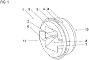
- the cover 1 according to this disclosure is shown on Fig 1 .
- a duct 2 with walls 8, 9 extends through the cover 1 and is adapted such that a circuit board laterally fits between the walls of the duct 2.
- the duct 1 has an outer envelope 3.
- the outer envelope 3 has cylindrical symmetry. It is envisaged that the outer envelope 3 has cylindrical symmetry and that a symmetry axis of the outer envelope 3 extends through the duct 2.
- the cover 1 also provides a seal 4.
- the (annular) seal 4 is adapted to mate with an (annular) groove on the inside of a tubular housing.
- the sealing element 4 circumferentially surrounds the outer envelope 3 of the duct 2.
- the sealing element 4 tapers toward the front end 10 with a front surface of the cover 1. It 4 terminates in the outer envelope 3.
- the instant disclosure teaches a cover 1, wherein the at least one seal 4 is an annular seal 4 and/or wherein the at least one seal 4 is configured to mate with an annular groove on the inside of a tubular housing 18.
- the tip 5 at the far end of the sealing element is part of the sealing element 4 and is arranged at a small distance from the outer envelope 3 of the cover 1.
- the gap in between the tip 5 of the sealing element 4 and the outer envelope 3 allows for a resiliently yieldable sealing element 4.
- the yieldable sealing element 4 can thus adapt to a groove on the inside of a tubular housing.
- the groove may, in particular, vary in size and in its surface may be uneven to some extent. Further, minor deviations of the groove from cylindrical symmetry may be tolerated.
- the instant disclosure teaches a cover 1, wherein the at least one seal 4 is resiliently yieldable so as to adapt to a groove on the inside of a tubular housing 18.
- sealing element 4 and the outer envelope 3 both have cylindrical symmetry. It is further envisaged that the sealing element 4 and the outer envelope 3 have the same symmetry axis.
- the tip 5 and the cover 1 form a single piece.
- the tip 5 and the cover 1 may be made of a suitable polymeric material.
- the material shall preferably be durable in the long term.
- the tip 5 may be made of a vulcanizing polymer such as SantopreneTM.
- the cover 1 and the tip 5 are made of flexible epoxy. The skilled person may also select other suitable materials for the cover 1.
- Fig 1 also shows the seal 4 with its tip 5 stands proud of the outer envelope 3.
- the outer surface of the seal 4 and the outer envelope 3 form an acute angle between 10 degrees and 40 degrees, more preferable between 15 degrees and 30 degrees, yet more preferable between 20 and 25 degrees. This angle may actually vary under the influence of external forces applied to the resiliently yieldable seal 4.
- the cover 1 may provide two latching members 6, 7.
- the members 6, 7 act to laterally latch onto suitable notches along the side edges of a circuit board, thereby fixating the circuit board.
- the latching members 6, 7 and the cover 1 form a single piece.
- the latching members 6, 7 and the cover 1 may, in particular, all be made of the same material.
- the instant disclosure teaches a cover 1, wherein the at least one seal 4 and the tip 5 and the outer envelope 3 and the cover 1 form a single piece (that is, they form a single-piece design) and/or wherein the at least one seal 4 and the tip 5 and the outer envelope 3 and the cover 1 are made of the same material.
- the instant disclosure also teaches a cover 1, wherein the outer envelope 3 and/or the at least one seal 4 and/or the tip 5 all have cylindrical symmetry with respect to an axis through the at least one duct 2.
- At least one wall 8 of the duct 2 is arranged at an angle.
- at least two walls 8, 9 of the duct 2 are arranged at an angle and/or form tapered surfaces.
- Fig 1 shows that the bottom wall 8 and the top wall 9 are not parallel.
- the duct 2 through the cover 1 provides an aperture for receiving a circuit board and that aperture narrows toward the front end 10 of the cover 1.
- the length of the cover 1 between its front end 5 and its rear end 11 is between 2 and 9 millimeters, more preferred between 3 and 7 millimeters, yet more preferred between 3 and 5 millimeters.
- the width of the cover 1 between opposite ends of the seal 4 lies between 5 and 15 millimeters, more preferably between 7 and 12 millimeters, yet more preferably between 9 and 10 millimeters.
- the ratio between the width and the length of the cover 1 is between 2 and 4, more preferred between 2.5 and 3, yet more preferred 2.66 or 2.8.
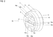
- Fig 2 shows the same cover 1, the same outer envelope 3, the same sealing element etc as Fig 1 .
- the main difference between the Fig 1 and Fig 2 is that Fig 2 shows the cover 1 from its front.
- Fig 1 provides a rear view of the cover 1.
- the cover 1 as shown on Fig 1 provides a rectangular opening 12 at its 1 front end 10.
- the opening 12 thus is an opening 12 in the front surface of the cover 1 such that a circuit board may penetrate the front surface and enter the duct 2.
- the rectangular opening 12 is especially adapted to receive a (printed and/or elongated) circuit board.
- the height of the rectangular opening 12 along the axis 13a, 13b therefore is between 1 and 2.5 millimeters, preferably 1.1 millimeters or 1.2 millimeters or 1.3 millimeters or 1.4 millimeters or 1.5 millimeters or 1.8 millimeters or 1.9 millimeters or 2.0 millimeters or 2.1 millimeters or 2.2 millimeters. It is envisaged that the rectangular opening 12 is wider at its entry 10 than inside the duct 2 and narrows toward the rear end 11 of the duct 2. Consequently, it will be less difficult to insert a (printed) circuit board into the rectangular opening 12.
- the instant disclosure teaches a cover 1, wherein the opening 12 is rectangular and/or wherein the width of the opening 12 and/or the height of the opening 12 are such that a circuit board 20 may fit through the opening 12.
- the width of the rectangular opening 12 along the axis 14a, 14b is between 3 and 10 millimeters, more preferred between 3 and 8 millimeters, yet more preferred between 4 and 6 millimeters.
- a plurality of apertures 15a, 15b, 15c, 15d are arranged in the front surface at the front end 10 of the cover 1.
- the cover 1 preferably comprises between 2 and 6 such apertures. Yet more preferably, the cover 1 comprises 4 such apertures. Typically, the diameter of these apertures is less than a millimeter.
- the cross-sections of the apertures 15a, 15b, 15c, 15d may be quadratic, rectangular, triangular, oval, circular in shape or any combinations thereof. The cross-section of the apertures may, in particular, take on a shape as shown on Fig 2 .
- the apertures 15a, 15b, 15c, 15d reduce to the overall stiffness of the cover 1.
- the apertures 15a, 15b, 15c, 15d thereby make the cover 1 suitable for terminating a wide range of tubular housings. It is envisaged that the apertures 15a, 15b, 15c, 15d are actually recesses. In other words, the apertures 15a, 15b, 15d need not extend through the cover 1.
- the instant disclosure teaches a cover 1, wherein a plurality of apertures 15a, 15b, 15c, 15d is, preferably four apertures 15a, 15b, 15c, 15d are, arranged in the front surface of the cover 1.
- the outer envelope 3 provides a tapered end 16 toward the front end 10 of the cover 1.
- the tapered end 16 reduces the effort involved in fitting the cover 1 to a tubular housing.
- the duct 2 provides side walls and lateral guide runners 17.
- the guide runners 17 are laterally arranged along opposite side walls of the duct 2. Ideally, there will be lateral guide runners 17 along either of the two side wall of the duct 2.
- the lateral guide runners 17 act to fixate the position of a(n elongated) circuit board extending through the duct 2.
- the lateral guide runners 17 also act to limit and/or to (substantially) prevent play of a (printed) circuit board inside the duct 2.
- the instant disclosure teaches a cover 1, wherein the at least one duct 2 provides guide runners 17 on either side wall of the at least one duct 2.
- the guide runners (17) all have the same width.
- the guide runners (17) are between 0.3 and 0.9 mm in width, preferred between 0.4 and 0.7 mm in width, yet more preferred 0.55 or 0.65 mm in width.
- a tubular housing 18 with a cover 1 is fitted to the tubular housing 18.
- the tubular housing 18 of Fig 3 comprises end portions 19a, 19b. It is envisaged that the tubular housing 18 forms a single piece together with the end portions 19a, 19b.
- the front end of the cover 1 is fitted to the tubular housing 18 such that the front surface of the cover 1 is flush with the inner surfaces of the end portions 19a, 19b.
- the position of the cover 1 relative to the tubular housing 18 may be defined by the seal 4.
- the seal 4 then mates with a flat surface or with (a) reciprocating groove(s) in the inner wall of the tubular housing 18. The cover 18 is thus prevented from moving along the inside the tubular housing 18.
- Fig 3 shows a (printed) circuit board inserted 20 into the cover 1.
- the printed circuit board 20 may have a number of electric and/or electronic components 21a, 21b mounted on its surface. It is also envisaged that surface-mounted devices (SMD) may be arranged on the (printed) circuit board 20.
- SMD surface-mounted devices
- the (printed) circuit board 20 of Fig 3 may as well be replaced by a laminate or by a sheet or similar with suitable dimensions.
- the rectangular opening 12 of the cover 1 mates with especially adapted grooves on the surface of a (printed) circuit board 20.
- opposite lips 12a, 12b of the rectangular opening 12 may mate with especially adapted grooves on the surface of a (printed) circuit board 20.
- One or two walls of the rectangular opening 12 may, by way on non-limiting example, mate with the grooves on the surface of a printed circuit board.
- the instant disclosure teaches a cover 1, wherein the opening 12 provides at least one lip 12a, 12b and the at least one lip 12a, 12b is configured to snugly receive the surface of a circuit board 18 such that the arrangement becomes fluid-tight.
- cover 1 and the (printed) circuit board 20 as well as the tubular housing 18 are part of a duct sensor. It is further envisaged that the cover 1 connects to the walls of the tubular housing 18. In particular, the seal 4 will connect to the walls of the tubular housing 18 and/or the front surface of the cover 1 will connect to the inner surfaces of the end portions 19a, 19b. It is an object of any of these connections that no uncured potting compound may leak in between the cover 1 and the tubular housing 18.
- the instant disclosure teaches a cover 1, wherein the opening 12 provides at least one lip 12a, 12b and the at least one lip 12a, 12b is configured to mate with a reciprocating groove in the surface of a circuit board 20 such that the arrangement becomes fluid-tight.
- the cover 1 connects to the surface of the (printed) circuit board 20.
- the lips 12a, 12b of the rectangular opening 12 will connect to the surface of the circuit board 20. It is an object of any of these connections that no uncured potting compound may leak in between the cover 1 and the circuit board 20.
- the cross-section of the tubular housing 18 taken perpendicular to an axis defined by the circuit board 20 is preferably circular. That is, the tubular housing 18 has cylindrical symmetry. In an alternate embodiment, the cross-section of the tubular housing 18 may as well be oval, rectangular, quadratic or any suitable combination thereof. The skilled person chooses a shape of the cover 1 in accordance with the geometry of the tubular housing 1.
- the tubular housing 18 may be made of any suitable material such as metallic materials and/or polymeric materials.
- the tubular housing 18 is made of (stainless) steel.
- the tubular housing 18 may, in particular, be made of austenitic or ferritic steel.
- the tubular housing 18 may as well be made of a polymeric material such as epoxy, polyurethane, polyester, PETP and/or any suitable combination thereof and/or any glass-fiber reinforced formulation of these materials. This list of materials is by way of non-limiting example and is not exhaustive. The skilled person selects a material for the tubular housing 18 that is compatible with the material for the cover 1.
- the cover 1 is fitted to the tubular housing 18 in a manner such that the arrangement becomes fluid-impervious.
- the front surface of the cover 1 is flush with the end portions 19a, 19b of the tubular housing 18.
- the front surface of the cover 1 connects to the outer envelope 3 of the cover.
- the front surface also connects to the walls of the duct 2.
- the seal 4 mates with (a) reciprocating groove(s) on the inner wall of the tubular housing 18.
- the rectangular opening 12 of the cover 1 snugly receives the (printed) circuit board 20 or lamination.
- the skilled person chooses materials dimensions and tolerances such that no leakage will occur in between the circuit board 20 or lamination and the cover 1.
- the front surface of the cover 1, the seal 4 and/or the rectangular opening 12 act to ensure the arrangement is fluid-tight.
- tightness depends on the type and, in particular, on the viscosity of the fluid.
- the arrangement is impervious to fluids with dynamic viscosities between 1 and 100'000 milliPascal ⁇ sec, preferably between 10 and 50'000 milliPascal ⁇ sec, yet more preferably between 100 and 20'000 milliPascal ⁇ sec, even more preferably between 1000 and 20'000 milliPascal ⁇ sec.
- the skilled person chooses materials, dimensions and tolerances in accordance with the viscosity of the fluid.
- the instant disclosure teaches a cover 1, wherein the at least one seal 4 comprises a tip 5 and/or wherein the at least one seal 4 is configured to mate with a flat surface or with a reciprocating groove in an inner wall of a tubular housing 18 such that the arrangement becomes fluid-tight.
- the tubular housing 18, the printed circuit board 20, and the cover 1 form basic elements of a duct sensor. It is envisaged that the duct sensor according to this enclosure meets the criteria for IP45, IP55, IP65 protection or higher.
- the inside of the tubular housing 18 is cast in a suitable potting compound. This step may typically be carried out when manufacturing a duct sensor.
- the potting compound eventually acts to protect electric and/or electronic components 21a, 21b inside the tubular housing 18.
- the potting compound may also function to improve on electrical insulation. Further, the potting compound may eventually protect the assembly against mechanical shock and ambient stresses such as ingress of fluids, in particular against ingress of moisture.
- a suitable potting compound such as epoxy resins, polyester resins, (room temperature vulcanizing) silicone resins and any suitable combinations thereof.
- a potting compound may be chosen that cures at room temperature or at elevated temperatures. This list is by way of non-limiting example.
- the skilled person considers the dimensions of the tubular housing when selecting a potting compound prone to heat shrink.
- the skilled person also selects a potting compound that is compatible with the material of the tubular housing 18 and is compatible with the material of the cover 1.
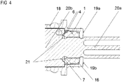
- FIG 4 another cross-sectional view of the assembly of Fig 3 is provided.
- the view of Fig 4 is actually taken at an angle of 90 degrees compared to the orientation of Fig 3 .
- Fig 4 shows a (printed) circuit board 20 with sections outside 20a and inside 20b the tubular housing 18.
- the cover 1 separates the inside section 20b from the outside section 20a of the circuit board 20.
- the outside section 20a of the circuit board may carry a humidity sensor such as a Sensirion SHT20 sensor, a Sensirion SHT21 sensor, Sensirion SHT25 sensor, a Si7005-B-GM1R sensor, a SI7015-A10-GM1 sensor, a Si7020-A10-GM sensor, a Si7021-A10-GM sensor, a Si7021-A10-GM1 sensor, a Si7005-B-FM1R sensor, a Si7013-A10-GM sensor, a Si7013-A10-GM1 sensor, or a Si7005-B-GM1 sensor available from Silicon Labs.
- a humidity sensor such as a Sensirion SHT20 sensor, a Sensirion SHT21 sensor, Sensirion S
- the skilled person may as well select a temperature sensor such as a PT100, a PT1000, a PTC or a NTC sensor. These lists are by way of non-limiting example.
- the skilled person may also select other temperature and/or humidity and/or moisture and/or (atmospheric) pressure and/or light sensors.
- the end portions 19a, 19b of the tubular housing 18 mate with reciprocating lateral notches in the circuit board 20.
- the lateral notches together with the end portions 19a, 19b define the position of the circuit board 20 with respect to the tubular housing 18.
- the end portions 19a, 19b and the reciprocating notches may, but need not ensure fluid-tightness of the arrangement. It is envisaged that fluid-tightness is primarily achieved through the cover 1. Without fluid-tightness between the end portions 19a, 19b and the reciprocating lateral notches, the corresponding technical constraints and tolerances may be relaxed to some extent.
- FIG 4 also provides details of how the latching members 6, 7 latch onto lateral notches 21 along both sides of the circuit board 20. It is envisaged that each of the lateral notches 21 forms a sector of a circle. In alternate embodiments, the notches 21 may be shaped quadratic, rectangular, oval, triangular, or any suitable combination thereof.
- the latching members 6, 7 thereby define the position of the cover 1 with respect to the circuit board 20.
- the latching members 6, 7 and the end portions 19a, 19b define the position of the cover 1 with respect to the tubular housing 18.
- the instant disclosure teaches a duct sensor comprising a tubular housing 18 with end portions 19a, 19b, a circuit board 20, and a cover 1 as detailed in this disclosure, wherein the cover 1 is mounted inside the tubular housing 18, wherein the circuit board 20 extends through the cover 1.
- the instant disclosure teaches a duct sensor, wherein the end portions 19a, 19b provide inner surfaces and wherein the front surface of the cover 1 is flush with inner surfaces of the end portions 19a, 19b.
- the instant disclosure teaches a duct sensor, wherein the cover 1 connects to the walls of the tubular housing 18 such that no uncured potting compound will leak in between the cover 1 and the tubular housing 18.
- the instant disclosure teaches a duct sensor, wherein and the cover 1 connects to the circuit board 20 such that no uncured potting compound will leak in between the cover 1 and the tubular housing 18.
Landscapes
- Chemical & Material Sciences (AREA)
- Life Sciences & Earth Sciences (AREA)
- Health & Medical Sciences (AREA)
- Physics & Mathematics (AREA)
- General Physics & Mathematics (AREA)
- Chemical Kinetics & Catalysis (AREA)
- Electrochemistry (AREA)
- Molecular Biology (AREA)
- Analytical Chemistry (AREA)
- Biochemistry (AREA)
- General Health & Medical Sciences (AREA)
- Immunology (AREA)
- Pathology (AREA)
- Casings For Electric Apparatus (AREA)
- Measuring Fluid Pressure (AREA)
Claims (12)
- Abdeckung (1) für einen Kanalsensor, welche umfasst:eine äußere Hülle (3), welche die Abdeckung (1) in Umfangsrichtung umgibt und mit wenigstens einer Dichtung (4) verbunden ist, wobei die wenigstens eine Dichtung (4) von der äußeren Hülle (3) absteht und die äußere Hülle (3) in Umfangsrichtung umgibt,wenigstens einen Kanal (2) mit Wänden (8, 9) und mit gegenüberliegenden Seitenwänden, wobei sich der wenigstens eine Kanal (2) durch die Abdeckung (1) hindurch erstreckt,eine Vorderfläche, welche mit der äußeren Hülle (3) und mit den Wänden (8, 9) des wenigstens einen Kanals (2) verbunden ist,wobei der wenigstens eine Kanal (2) mehrere Führungsteile (17) umfasst, die seitlich entlang der gegenüberliegenden Seitenwände des Kanals (2) angeordnet sind,wobei die Abdeckung (1) eine Öffnung (12) in der Vorderfläche umfasst,wobei die Öffnung (12) einen Eingang zum Einführen einer Leiterplatte in den wenigstens einen Kanal (2) bereitstellt,wobei die mehreren Führungsteile (17) dafür ausgelegt sind, eine Leiterplatte (20) zu stützen, die sich durch den Kanal (2) erstreckt,wobei die mehreren Führungsteile (17) und die Öffnung (12) dafür ausgebildet sind, ein Spiel einer Leiterplatte (20) zu verhindern, die sich durch den Kanal (2) erstreckt,dadurch gekennzeichnet, dassdie wenigstens eine Dichtung (4) eine Spitze (5) umfasst, die am fernen Ende der Dichtung (4) angeordnet ist, unddie wenigstens eine Dichtung (4) und die Spitze (5) und die äußere Hülle (3) und die Abdeckung (1) ein einziges Teil bilden, unddie wenigstens eine Dichtung (4) so ausgebildet ist, dass sie mit einer flachen Fläche oder mit einer hin- und herverlaufenden Nut in einer Innenwand eines rohrförmigen Gehäuses (18) des Kanalsensors zusammenpasst, so dass die Anordnung fluiddicht wird.
- Abdeckung (1) nach Anspruch 1, wobei die Öffnung (12) rechteckig ist und/oder wobei die Breite der Öffnung (12) und/oder die Höhe der Öffnung (12) so beschaffen sind, dass eine Leiterplatte (20) durch die Öffnung (12) hindurchpasst.
- Abdeckung (1) nach Anspruch 1, wobei die wenigstens eine Dichtung (4) und die Spitze (5) und die äußere Hülle (3) und die Abdeckung (1) aus demselben Material hergestellt sind.
- Abdeckung (1) nach Anspruch 3, wobei die äußere Hülle (3) und/oder die wenigstens eine Dichtung (4) und/oder die Spitze (5) alle eine zylindrische Symmetrie in Bezug auf eine Achse durch den wenigstens einen Kanal (2) aufweisen.
- Abdeckung (1) nach einem der Ansprüche 1 bis 4, wobei die wenigstens eine Dichtung (4) elastisch nachgebend ist, so dass sie sich an eine Nut auf der Innenseite eines rohrförmigen Gehäuses (18) anpasst.
- Abdeckung (1) nach einem der Ansprüche 1 bis 5, wobei die wenigstens eine Dichtung (4) eine Ringdichtung (4) ist und/oder wobei die wenigstens eine Dichtung (4) so ausgebildet ist, dass sie mit einer Ringnut auf der Innenseite eines rohrförmigen Gehäuses (18) zusammenpasst.
- Abdeckung (1) nach einem der Ansprüche 1 bis 6, wobei der wenigstens eine Kanal (2) Führungsteile (17) auf jeder Seitenwand des wenigstens einen Kanals (2) bereitstellt.
- Abdeckung (1) nach einem der Ansprüche 1 bis 7, wobei die Öffnung (12) wenigstens eine Lippe (12a, 12b) bereitstellt und die wenigstens eine Lippe (12a, 12b) so ausgebildet ist, dass sie mit einer hin- und herverlaufenden Nut in der Oberfläche einer Leiterplatte (20) zusammenpasst, so dass die Anordnung fluiddicht wird.
- Abdeckung (1) nach einem der Ansprüche 1 bis 8, wobei die Öffnung (12) wenigstens eine Lippe (12a, 12b) bereitstellt und die wenigstens eine Lippe (12a, 12b) so ausgebildet ist, dass sie die Oberfläche einer Leiterplatte (18) enganliegend aufnimmt, so dass die Anordnung fluiddicht wird.
- Abdeckung (1) nach einem der Ansprüche 1 bis 9, wobei mehrere Löcher (15a, 15b, 15c, 15d), vorzugsweise vier Löcher (15a, 15b, 15c, 15d), in der Vorderfläche der Abdeckung (1) angeordnet sind.
- Kanalsensor, welcher umfasst:ein rohrförmiges Gehäuse (18) mit Endabschnitten (19a, 19b), eine Leiterplatte (20)und eine Abdeckung (1) nach einem der vorhergehenden Ansprüche,wobei die Abdeckung (1) innerhalb des rohrförmigen Gehäuses (18) angebracht ist,wobei sich die Leiterplatte (20) durch die Abdeckung (1) hindurch erstreckt.
- Kanalsensor nach Anspruch 11, wobei die Endabschnitte (19a, 19b) Innenflächen bereitstellen und wobei die Vorderfläche der Abdeckung (1) mit den Innenflächen der Endabschnitte (19a, 19b) bündig ist.
Priority Applications (1)
| Application Number | Priority Date | Filing Date | Title |
|---|---|---|---|
| EP15181401.9A EP3018472B1 (de) | 2014-10-29 | 2015-08-18 | Abdeckung für einen kanalfühler |
Applications Claiming Priority (2)
| Application Number | Priority Date | Filing Date | Title |
|---|---|---|---|
| EP14190958 | 2014-10-29 | ||
| EP15181401.9A EP3018472B1 (de) | 2014-10-29 | 2015-08-18 | Abdeckung für einen kanalfühler |
Publications (2)
| Publication Number | Publication Date |
|---|---|
| EP3018472A1 EP3018472A1 (de) | 2016-05-11 |
| EP3018472B1 true EP3018472B1 (de) | 2018-09-26 |
Family
ID=51844554
Family Applications (1)
| Application Number | Title | Priority Date | Filing Date |
|---|---|---|---|
| EP15181401.9A Active EP3018472B1 (de) | 2014-10-29 | 2015-08-18 | Abdeckung für einen kanalfühler |
Country Status (5)
| Country | Link |
|---|---|
| US (1) | US9689719B2 (de) |
| EP (1) | EP3018472B1 (de) |
| CN (1) | CN105570457B (de) |
| BR (1) | BR102015027042B1 (de) |
| RU (1) | RU2630604C2 (de) |
Families Citing this family (2)
| Publication number | Priority date | Publication date | Assignee | Title |
|---|---|---|---|---|
| CN106052736B (zh) * | 2016-07-18 | 2018-06-26 | 西安电子科技大学 | ZigBee技术环境监测系统的节点防护罩 |
| RU183094U1 (ru) * | 2018-03-26 | 2018-09-11 | Общество с ограниченной ответственностью "ЭРИС" | Насадка датчика газоанализатора |
Family Cites Families (14)
| Publication number | Priority date | Publication date | Assignee | Title |
|---|---|---|---|---|
| US3175391A (en) | 1961-09-08 | 1965-03-30 | Hygrodynamics Inc | Moisture tester |
| US6063249A (en) | 1998-05-12 | 2000-05-16 | General Motors Corporation | Oxygen sensor |
| JP4639515B2 (ja) * | 2000-06-30 | 2011-02-23 | 株式会社デンソー | ガスセンサ |
| US6658933B2 (en) * | 2001-06-22 | 2003-12-09 | Clesse Industries | Fill-level indicator for a liquefied-petroleum-gas tank |
| JP2003107047A (ja) * | 2001-10-01 | 2003-04-09 | Denso Corp | ガス濃度検出素子 |
| WO2004086023A1 (de) | 2003-03-27 | 2004-10-07 | Robert Bosch Gmbh | Messfühler |
| EP1577648B1 (de) * | 2004-03-15 | 2006-08-09 | Siemens Schweiz AG | Messeinrichtung |
| DE102004063173A1 (de) * | 2004-12-29 | 2006-07-13 | Robert Bosch Gmbh | Gasmessfühler |
| US8015873B2 (en) * | 2008-04-25 | 2011-09-13 | Hall David L | Detector housing |
| JP5002032B2 (ja) * | 2010-04-02 | 2012-08-15 | 日本特殊陶業株式会社 | ガスセンサ |
| RU114152U1 (ru) | 2011-09-22 | 2012-03-10 | Закрытое акционерное общество Промышленная группа "Метран" | Узел герметизации и крепления электронной платы в корпусе датчика давления |
| JP6058986B2 (ja) * | 2012-11-29 | 2017-01-11 | アズビル株式会社 | 差圧センサ |
| US9135801B2 (en) * | 2013-11-18 | 2015-09-15 | Firesys Ltd. | Fully mechanical pneumatic excessive heat or/and fire line-type detector, and system, methods, applications thereof |
| JP6535156B2 (ja) * | 2014-03-12 | 2019-06-26 | 日本碍子株式会社 | ガスセンサ |
-
2015
- 2015-08-18 EP EP15181401.9A patent/EP3018472B1/de active Active
- 2015-09-17 US US14/856,887 patent/US9689719B2/en active Active
- 2015-10-23 RU RU2015145769A patent/RU2630604C2/ru active
- 2015-10-26 BR BR102015027042-9A patent/BR102015027042B1/pt active IP Right Grant
- 2015-10-29 CN CN201510714545.3A patent/CN105570457B/zh active Active
Non-Patent Citations (1)
| Title |
|---|
| None * |
Also Published As
| Publication number | Publication date |
|---|---|
| RU2015145769A (ru) | 2017-04-28 |
| CN105570457A (zh) | 2016-05-11 |
| RU2630604C2 (ru) | 2017-09-11 |
| US20160123779A1 (en) | 2016-05-05 |
| US9689719B2 (en) | 2017-06-27 |
| CN105570457B (zh) | 2018-11-27 |
| EP3018472A1 (de) | 2016-05-11 |
| BR102015027042B1 (pt) | 2020-12-29 |
| BR102015027042A2 (pt) | 2016-07-05 |
Similar Documents
| Publication | Publication Date | Title |
|---|---|---|
| CN101179910B (zh) | 外壳的压力平衡装置 | |
| US7211914B2 (en) | Electric motor having a high degree of protection against the ingress of foreign particles and moisture | |
| US20160211727A1 (en) | Motor assembly | |
| US9560779B2 (en) | Thermal stabilization of temperature sensitive components | |
| JP6423552B2 (ja) | 電子制御装置 | |
| EP3073810A1 (de) | Elektronische steuereinheit mit gehäusestabilisierungselement und gehäuse für elektronische steuereinheit | |
| US20200248811A1 (en) | Seal Structure | |
| EP3018472B1 (de) | Abdeckung für einen kanalfühler | |
| CN107637189A (zh) | 过程自动化中使用的现场设备 | |
| US10039197B2 (en) | Housing having an opening and a covering device | |
| DE202016003218U1 (de) | Anlege-Temperatursensor | |
| US9807895B2 (en) | Seal for a housing of an electronic circuit arrangement | |
| US8776598B2 (en) | Liquid sensor | |
| US9901004B2 (en) | Housing for electronic control unit | |
| CN103687395B (zh) | 气密的外壳装置 | |
| KR20190034678A (ko) | 자가-지지 중합체 재료 라이너를 포함하는 연료 전지 매니폴드 조립체 | |
| US9368905B2 (en) | Potting compound chamber designs for electrical connectors | |
| KR20070061782A (ko) | 제어 장치 밀봉 | |
| CN108062967B (zh) | 传感器的应对结露构造 | |
| US20120024876A1 (en) | Sealed enclosure and system | |
| JP6613831B2 (ja) | コネクタ | |
| JP4501585B2 (ja) | 防水構造を持つ電気回路部品および筐体 | |
| US20220196143A1 (en) | Transmission housing, sensor installation kit and transmission | |
| JP7050645B2 (ja) | センサ | |
| JP5103572B2 (ja) | 角度検出器 |
Legal Events
| Date | Code | Title | Description |
|---|---|---|---|
| PUAI | Public reference made under article 153(3) epc to a published international application that has entered the european phase |
Free format text: ORIGINAL CODE: 0009012 |
|
| AK | Designated contracting states |
Kind code of ref document: A1 Designated state(s): AL AT BE BG CH CY CZ DE DK EE ES FI FR GB GR HR HU IE IS IT LI LT LU LV MC MK MT NL NO PL PT RO RS SE SI SK SM TR |
|
| AX | Request for extension of the european patent |
Extension state: BA ME |
|
| STAA | Information on the status of an ep patent application or granted ep patent |
Free format text: STATUS: REQUEST FOR EXAMINATION WAS MADE |
|
| 17P | Request for examination filed |
Effective date: 20161104 |
|
| RBV | Designated contracting states (corrected) |
Designated state(s): AL AT BE BG CH CY CZ DE DK EE ES FI FR GB GR HR HU IE IS IT LI LT LU LV MC MK MT NL NO PL PT RO RS SE SI SK SM TR |
|
| STAA | Information on the status of an ep patent application or granted ep patent |
Free format text: STATUS: EXAMINATION IS IN PROGRESS |
|
| 17Q | First examination report despatched |
Effective date: 20180223 |
|
| REG | Reference to a national code |
Ref country code: DE Ref legal event code: R079 Ref document number: 602015016852 Country of ref document: DE Free format text: PREVIOUS MAIN CLASS: G01N0027403000 Ipc: G01N0027407000 |
|
| GRAP | Despatch of communication of intention to grant a patent |
Free format text: ORIGINAL CODE: EPIDOSNIGR1 |
|
| STAA | Information on the status of an ep patent application or granted ep patent |
Free format text: STATUS: GRANT OF PATENT IS INTENDED |
|
| RIC1 | Information provided on ipc code assigned before grant |
Ipc: G01N 27/407 20060101AFI20180426BHEP |
|
| INTG | Intention to grant announced |
Effective date: 20180524 |
|
| GRAS | Grant fee paid |
Free format text: ORIGINAL CODE: EPIDOSNIGR3 |
|
| GRAA | (expected) grant |
Free format text: ORIGINAL CODE: 0009210 |
|
| STAA | Information on the status of an ep patent application or granted ep patent |
Free format text: STATUS: THE PATENT HAS BEEN GRANTED |
|
| AK | Designated contracting states |
Kind code of ref document: B1 Designated state(s): AL AT BE BG CH CY CZ DE DK EE ES FI FR GB GR HR HU IE IS IT LI LT LU LV MC MK MT NL NO PL PT RO RS SE SI SK SM TR |
|
| REG | Reference to a national code |
Ref country code: GB Ref legal event code: FG4D |
|
| REG | Reference to a national code |
Ref country code: CH Ref legal event code: EP |
|
| REG | Reference to a national code |
Ref country code: AT Ref legal event code: REF Ref document number: 1046614 Country of ref document: AT Kind code of ref document: T Effective date: 20181015 |
|
| REG | Reference to a national code |
Ref country code: IE Ref legal event code: FG4D |
|
| REG | Reference to a national code |
Ref country code: DE Ref legal event code: R096 Ref document number: 602015016852 Country of ref document: DE |
|
| REG | Reference to a national code |
Ref country code: NL Ref legal event code: MP Effective date: 20180926 |
|
| PG25 | Lapsed in a contracting state [announced via postgrant information from national office to epo] |
Ref country code: FI Free format text: LAPSE BECAUSE OF FAILURE TO SUBMIT A TRANSLATION OF THE DESCRIPTION OR TO PAY THE FEE WITHIN THE PRESCRIBED TIME-LIMIT Effective date: 20180926 Ref country code: RS Free format text: LAPSE BECAUSE OF FAILURE TO SUBMIT A TRANSLATION OF THE DESCRIPTION OR TO PAY THE FEE WITHIN THE PRESCRIBED TIME-LIMIT Effective date: 20180926 Ref country code: NO Free format text: LAPSE BECAUSE OF FAILURE TO SUBMIT A TRANSLATION OF THE DESCRIPTION OR TO PAY THE FEE WITHIN THE PRESCRIBED TIME-LIMIT Effective date: 20181226 Ref country code: GR Free format text: LAPSE BECAUSE OF FAILURE TO SUBMIT A TRANSLATION OF THE DESCRIPTION OR TO PAY THE FEE WITHIN THE PRESCRIBED TIME-LIMIT Effective date: 20181227 Ref country code: BG Free format text: LAPSE BECAUSE OF FAILURE TO SUBMIT A TRANSLATION OF THE DESCRIPTION OR TO PAY THE FEE WITHIN THE PRESCRIBED TIME-LIMIT Effective date: 20181226 Ref country code: SE Free format text: LAPSE BECAUSE OF FAILURE TO SUBMIT A TRANSLATION OF THE DESCRIPTION OR TO PAY THE FEE WITHIN THE PRESCRIBED TIME-LIMIT Effective date: 20180926 Ref country code: LT Free format text: LAPSE BECAUSE OF FAILURE TO SUBMIT A TRANSLATION OF THE DESCRIPTION OR TO PAY THE FEE WITHIN THE PRESCRIBED TIME-LIMIT Effective date: 20180926 |
|
| REG | Reference to a national code |
Ref country code: LT Ref legal event code: MG4D |
|
| PG25 | Lapsed in a contracting state [announced via postgrant information from national office to epo] |
Ref country code: HR Free format text: LAPSE BECAUSE OF FAILURE TO SUBMIT A TRANSLATION OF THE DESCRIPTION OR TO PAY THE FEE WITHIN THE PRESCRIBED TIME-LIMIT Effective date: 20180926 Ref country code: LV Free format text: LAPSE BECAUSE OF FAILURE TO SUBMIT A TRANSLATION OF THE DESCRIPTION OR TO PAY THE FEE WITHIN THE PRESCRIBED TIME-LIMIT Effective date: 20180926 Ref country code: AL Free format text: LAPSE BECAUSE OF FAILURE TO SUBMIT A TRANSLATION OF THE DESCRIPTION OR TO PAY THE FEE WITHIN THE PRESCRIBED TIME-LIMIT Effective date: 20180926 |
|
| REG | Reference to a national code |
Ref country code: AT Ref legal event code: MK05 Ref document number: 1046614 Country of ref document: AT Kind code of ref document: T Effective date: 20180926 |
|
| PG25 | Lapsed in a contracting state [announced via postgrant information from national office to epo] |
Ref country code: ES Free format text: LAPSE BECAUSE OF FAILURE TO SUBMIT A TRANSLATION OF THE DESCRIPTION OR TO PAY THE FEE WITHIN THE PRESCRIBED TIME-LIMIT Effective date: 20180926 Ref country code: CZ Free format text: LAPSE BECAUSE OF FAILURE TO SUBMIT A TRANSLATION OF THE DESCRIPTION OR TO PAY THE FEE WITHIN THE PRESCRIBED TIME-LIMIT Effective date: 20180926 Ref country code: IS Free format text: LAPSE BECAUSE OF FAILURE TO SUBMIT A TRANSLATION OF THE DESCRIPTION OR TO PAY THE FEE WITHIN THE PRESCRIBED TIME-LIMIT Effective date: 20190126 Ref country code: EE Free format text: LAPSE BECAUSE OF FAILURE TO SUBMIT A TRANSLATION OF THE DESCRIPTION OR TO PAY THE FEE WITHIN THE PRESCRIBED TIME-LIMIT Effective date: 20180926 Ref country code: PL Free format text: LAPSE BECAUSE OF FAILURE TO SUBMIT A TRANSLATION OF THE DESCRIPTION OR TO PAY THE FEE WITHIN THE PRESCRIBED TIME-LIMIT Effective date: 20180926 Ref country code: NL Free format text: LAPSE BECAUSE OF FAILURE TO SUBMIT A TRANSLATION OF THE DESCRIPTION OR TO PAY THE FEE WITHIN THE PRESCRIBED TIME-LIMIT Effective date: 20180926 Ref country code: RO Free format text: LAPSE BECAUSE OF FAILURE TO SUBMIT A TRANSLATION OF THE DESCRIPTION OR TO PAY THE FEE WITHIN THE PRESCRIBED TIME-LIMIT Effective date: 20180926 Ref country code: IT Free format text: LAPSE BECAUSE OF FAILURE TO SUBMIT A TRANSLATION OF THE DESCRIPTION OR TO PAY THE FEE WITHIN THE PRESCRIBED TIME-LIMIT Effective date: 20180926 Ref country code: AT Free format text: LAPSE BECAUSE OF FAILURE TO SUBMIT A TRANSLATION OF THE DESCRIPTION OR TO PAY THE FEE WITHIN THE PRESCRIBED TIME-LIMIT Effective date: 20180926 |
|
| PG25 | Lapsed in a contracting state [announced via postgrant information from national office to epo] |
Ref country code: SM Free format text: LAPSE BECAUSE OF FAILURE TO SUBMIT A TRANSLATION OF THE DESCRIPTION OR TO PAY THE FEE WITHIN THE PRESCRIBED TIME-LIMIT Effective date: 20180926 Ref country code: SK Free format text: LAPSE BECAUSE OF FAILURE TO SUBMIT A TRANSLATION OF THE DESCRIPTION OR TO PAY THE FEE WITHIN THE PRESCRIBED TIME-LIMIT Effective date: 20180926 Ref country code: PT Free format text: LAPSE BECAUSE OF FAILURE TO SUBMIT A TRANSLATION OF THE DESCRIPTION OR TO PAY THE FEE WITHIN THE PRESCRIBED TIME-LIMIT Effective date: 20190126 |
|
| REG | Reference to a national code |
Ref country code: DE Ref legal event code: R097 Ref document number: 602015016852 Country of ref document: DE |
|
| PG25 | Lapsed in a contracting state [announced via postgrant information from national office to epo] |
Ref country code: DK Free format text: LAPSE BECAUSE OF FAILURE TO SUBMIT A TRANSLATION OF THE DESCRIPTION OR TO PAY THE FEE WITHIN THE PRESCRIBED TIME-LIMIT Effective date: 20180926 |
|
| PLBE | No opposition filed within time limit |
Free format text: ORIGINAL CODE: 0009261 |
|
| STAA | Information on the status of an ep patent application or granted ep patent |
Free format text: STATUS: NO OPPOSITION FILED WITHIN TIME LIMIT |
|
| 26N | No opposition filed |
Effective date: 20190627 |
|
| PG25 | Lapsed in a contracting state [announced via postgrant information from national office to epo] |
Ref country code: SI Free format text: LAPSE BECAUSE OF FAILURE TO SUBMIT A TRANSLATION OF THE DESCRIPTION OR TO PAY THE FEE WITHIN THE PRESCRIBED TIME-LIMIT Effective date: 20180926 |
|
| PG25 | Lapsed in a contracting state [announced via postgrant information from national office to epo] |
Ref country code: TR Free format text: LAPSE BECAUSE OF FAILURE TO SUBMIT A TRANSLATION OF THE DESCRIPTION OR TO PAY THE FEE WITHIN THE PRESCRIBED TIME-LIMIT Effective date: 20180926 |
|
| GBPC | Gb: european patent ceased through non-payment of renewal fee |
Effective date: 20190818 |
|
| PG25 | Lapsed in a contracting state [announced via postgrant information from national office to epo] |
Ref country code: MC Free format text: LAPSE BECAUSE OF FAILURE TO SUBMIT A TRANSLATION OF THE DESCRIPTION OR TO PAY THE FEE WITHIN THE PRESCRIBED TIME-LIMIT Effective date: 20180926 Ref country code: LU Free format text: LAPSE BECAUSE OF NON-PAYMENT OF DUE FEES Effective date: 20190818 |
|
| REG | Reference to a national code |
Ref country code: BE Ref legal event code: MM Effective date: 20190831 |
|
| PG25 | Lapsed in a contracting state [announced via postgrant information from national office to epo] |
Ref country code: IE Free format text: LAPSE BECAUSE OF NON-PAYMENT OF DUE FEES Effective date: 20190818 |
|
| PG25 | Lapsed in a contracting state [announced via postgrant information from national office to epo] |
Ref country code: GB Free format text: LAPSE BECAUSE OF NON-PAYMENT OF DUE FEES Effective date: 20190818 Ref country code: BE Free format text: LAPSE BECAUSE OF NON-PAYMENT OF DUE FEES Effective date: 20190831 |
|
| PG25 | Lapsed in a contracting state [announced via postgrant information from national office to epo] |
Ref country code: CY Free format text: LAPSE BECAUSE OF FAILURE TO SUBMIT A TRANSLATION OF THE DESCRIPTION OR TO PAY THE FEE WITHIN THE PRESCRIBED TIME-LIMIT Effective date: 20180926 |
|
| PG25 | Lapsed in a contracting state [announced via postgrant information from national office to epo] |
Ref country code: MT Free format text: LAPSE BECAUSE OF FAILURE TO SUBMIT A TRANSLATION OF THE DESCRIPTION OR TO PAY THE FEE WITHIN THE PRESCRIBED TIME-LIMIT Effective date: 20180926 Ref country code: HU Free format text: LAPSE BECAUSE OF FAILURE TO SUBMIT A TRANSLATION OF THE DESCRIPTION OR TO PAY THE FEE WITHIN THE PRESCRIBED TIME-LIMIT; INVALID AB INITIO Effective date: 20150818 |
|
| PG25 | Lapsed in a contracting state [announced via postgrant information from national office to epo] |
Ref country code: MK Free format text: LAPSE BECAUSE OF FAILURE TO SUBMIT A TRANSLATION OF THE DESCRIPTION OR TO PAY THE FEE WITHIN THE PRESCRIBED TIME-LIMIT Effective date: 20180926 |
|
| PGFP | Annual fee paid to national office [announced via postgrant information from national office to epo] |
Ref country code: FR Payment date: 20250827 Year of fee payment: 11 |
|
| REG | Reference to a national code |
Ref country code: CH Ref legal event code: U11 Free format text: ST27 STATUS EVENT CODE: U-0-0-U10-U11 (AS PROVIDED BY THE NATIONAL OFFICE) Effective date: 20251110 |
|
| PGFP | Annual fee paid to national office [announced via postgrant information from national office to epo] |
Ref country code: DE Payment date: 20251020 Year of fee payment: 11 |
|
| PGFP | Annual fee paid to national office [announced via postgrant information from national office to epo] |
Ref country code: CH Payment date: 20251110 Year of fee payment: 11 |