EP1577648B1 - Messeinrichtung - Google Patents
Messeinrichtung Download PDFInfo
- Publication number
- EP1577648B1 EP1577648B1 EP04006043A EP04006043A EP1577648B1 EP 1577648 B1 EP1577648 B1 EP 1577648B1 EP 04006043 A EP04006043 A EP 04006043A EP 04006043 A EP04006043 A EP 04006043A EP 1577648 B1 EP1577648 B1 EP 1577648B1
- Authority
- EP
- European Patent Office
- Prior art keywords
- circuit board
- sensor
- printed circuit
- module according
- teeth
- Prior art date
- Legal status (The legal status is an assumption and is not a legal conclusion. Google has not performed a legal analysis and makes no representation as to the accuracy of the status listed.)
- Expired - Lifetime
Links
- 238000007789 sealing Methods 0.000 claims description 3
- 150000001875 compounds Chemical class 0.000 claims description 2
- 238000007493 shaping process Methods 0.000 claims description 2
- 238000004519 manufacturing process Methods 0.000 abstract description 3
- WABPQHHGFIMREM-UHFFFAOYSA-N lead(0) Chemical compound [Pb] WABPQHHGFIMREM-UHFFFAOYSA-N 0.000 description 6
- 238000013461 design Methods 0.000 description 5
- 230000008901 benefit Effects 0.000 description 3
- 238000000034 method Methods 0.000 description 3
- 230000008569 process Effects 0.000 description 3
- 230000008859 change Effects 0.000 description 2
- 238000004891 communication Methods 0.000 description 2
- 238000012937 correction Methods 0.000 description 2
- 230000001419 dependent effect Effects 0.000 description 2
- 238000001514 detection method Methods 0.000 description 2
- 238000010586 diagram Methods 0.000 description 2
- 238000012544 monitoring process Methods 0.000 description 2
- 230000032683 aging Effects 0.000 description 1
- 238000004378 air conditioning Methods 0.000 description 1
- 230000005540 biological transmission Effects 0.000 description 1
- 238000005266 casting Methods 0.000 description 1
- 230000001143 conditioned effect Effects 0.000 description 1
- 238000010276 construction Methods 0.000 description 1
- 238000003745 diagnosis Methods 0.000 description 1
- 238000007599 discharging Methods 0.000 description 1
- 230000006870 function Effects 0.000 description 1
- 238000010438 heat treatment Methods 0.000 description 1
- 238000005304 joining Methods 0.000 description 1
- 230000013011 mating Effects 0.000 description 1
- 238000000465 moulding Methods 0.000 description 1
- 239000004033 plastic Substances 0.000 description 1
- 230000009467 reduction Effects 0.000 description 1
- 230000001105 regulatory effect Effects 0.000 description 1
- 239000011347 resin Substances 0.000 description 1
- 229920005989 resin Polymers 0.000 description 1
- 239000000565 sealant Substances 0.000 description 1
- 239000002356 single layer Substances 0.000 description 1
- 229910000679 solder Inorganic materials 0.000 description 1
- 238000003860 storage Methods 0.000 description 1
- 229920001169 thermoplastic Polymers 0.000 description 1
- 239000004416 thermosoftening plastic Substances 0.000 description 1
- 238000009423 ventilation Methods 0.000 description 1
Images

Classifications
-
- G—PHYSICS
- G01—MEASURING; TESTING
- G01D—MEASURING NOT SPECIALLY ADAPTED FOR A SPECIFIC VARIABLE; ARRANGEMENTS FOR MEASURING TWO OR MORE VARIABLES NOT COVERED IN A SINGLE OTHER SUBCLASS; TARIFF METERING APPARATUS; MEASURING OR TESTING NOT OTHERWISE PROVIDED FOR
- G01D11/00—Component parts of measuring arrangements not specially adapted for a specific variable
- G01D11/24—Housings ; Casings for instruments
- G01D11/245—Housings for sensors
Definitions
- the invention relates to a measuring device referred to in the preamble of claim 1 Art.
- Such measuring devices are advantageously used in heating, ventilation and air conditioning (HVAC) for buildings to capture a process variable.
- HVAC heating, ventilation and air conditioning
- Such a measuring device is an example of a device for detecting the humidity in a room or in a device for supplying or discharging air.
- Such measuring devices can also be used for detecting the illuminance or for gas detection.
- the present invention can be used in principle if process variables are detected with sensor elements having electrical connecting wires. Such a measuring device can therefore also be used in a vehicle.
- a known measuring device for detecting the humidity has a capacitive humidity sensor and a temperature sensor. For the detection of electrical measuring signals connecting wires of the two sensors are connected via plug or solder connections with an electronic circuit or with a connection cable.
- the invention is based on the object to provide a measuring device with electrical sensors in which uninsulated thin leads of a sensor - for example, those with a wire diameter in the order of 0.1 mm - reproducible, safe and inexpensive with a circuit board are connected.
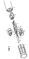
- FIG. 1, 1 designates a sensor module with a first sensor element 2 and a second sensor element 3, with a single-layer or multilayer printed circuit board 4, with a first shell 5 and a second shell 6.
- the first sensor element 2 is a humidity sensor and the second sensor element 3 is a temperature sensor.
- the two sensor elements 2 and 3 for example, the relative humidity of a room or an air duct can be detected.
- the sensor module 1 has a plurality of sensor elements or only a single sensor element.
- the two shells 5 and 6 are designed such that they put together a holding function for the sensor module 1 exercise.
- the sensor elements 2 and 3 are protected by a cover or by a filter 7, which are advantageously attached to the sensor module 1 via the two shells 5 and 6.
- the circuit board 4 can be covered with a sensor tube 8, which is advantageously attached to the sensor module 1 via the two shells 5 and 6.
- the printed circuit board 4 is connected, for example via a cable 9 provided with a plug, to a higher-level system, typically to a control or regulating device.
- a communication device for wireless data transmission between the sensor module and the higher-level system is arranged on the printed circuit board 4.
- the two shells 5 and 6 serve in an advantageous manner during assembly of the sensor module 1 as a production tool.
- Forms of the printed circuit board 4 and the first shell 5 are advantageously matched to one another such that the printed circuit board 4 is stored in the first shell 5 at least in a region 10 in which the sensor elements 2 and 3 are to be contacted with the printed circuit board 4.
- the shells 5 and 6 and the circuit board 4 matched design means on, by which the guide plate 4 is held in the mounted state in the two shells 5 and 6.
- the first shell 5 For storage of the printed circuit board 4, the first shell 5 by way of example on opposite paragraphs 11, through which the positioning of the circuit board 4 is determined on the first shell 5.
- the first shell 5 has, for example, cams 12 which, in conjunction with recesses 13 formed on the printed circuit board 4, hold the printed circuit board 4 in the shells 4 and 5 in the mounted state.
- the circuit board 4 is mounted in the usable as a production tool first shell 5, wherein the second shell 6 is shown in the lifted state.
- a first tooth 20, a second tooth 21 and a third tooth 22 belong to a first row of teeth arranged against the sensor elements 2 and 3, which is advantageously formed in the first shell 5 and through which electrical connection wires 23, 24 and 25 of the sensor elements 2 and 3 are insulated from one another at a certain distance from the printed circuit board 4.
- the electrical connection wires 23, 24 and 25 are soldered directly to the printed circuit board 4.
- the second tooth 21 is shown in a section.
- Denoted by 26 is a fourth tooth, which belongs to a second row of teeth, which is formed offset in relation to the first row of teeth against the printed circuit board in the second shell 6.
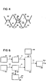
- the first row of teeth formed in the first shell 5 and the second row of teeth formed in the second shell 6 are partially and simplified in FIG 4, wherein the two shells 5 and 6 are not yet fully assembled, and the view of the sensor elements 2 and 3 is shown forth.
- the second row of teeth has a fifth tooth 27 and a sixth tooth 28.
- the row of teeth formed in the first shell 5 with the teeth 20, 21 and 22 and the row of teeth formed in the second shell 6 with the teeth 26, 27 and 28, which are opposite to the teeth 20, 21 and 22 of the first row of teeth form a arranged between the circuit board 4 and the sensor elements 2 and 3 guide means by which the electrical leads 23, 24 and 25 isolated from each other at a certain distance to the circuit board 4 are guided.
- the guide means is adaptable to exacting requirements within the exact design and design within wide limits; for example, the number and mass of the sensor elements used, the shape and wire diameter of the connecting wires, a required quality of the seal around the connecting wires and a required creepage or even dielectric strength between individual connecting wires.
- the two shells 5 and 6 are made of a plastic, in particular certain thermoplastics are advantageous, which hardly absorb moisture.
- the teeth 20, 21, 22, 26, 27 and 28 are formed substantially wedge-shaped.
- the two rows of teeth are designed and arranged in such a way in that a first channel 30 associated with a first connecting wire 23 is delimited by two adjacent teeth 20 and 21 of the first row of teeth and by two adjacent teeth 27 and 26 of the second row of teeth.
- a second channel 31 associated with a second lead wire 24 is bounded by two further adjacent teeth 21 and 22 of the first row of teeth and two further adjacent teeth 26 and 28 of the second row of teeth.
- the cross section of the first channel 30 and the cross section of the second channel 31 decrease more and more, wherein the inserted in the first channel 30 connecting wire and captured in a between the first tooth 20 and the second tooth 21st formed saddle 32 is positioned and wherein also the inserted in the second channel 31 connecting wire is captured and positioned in a formed between the second tooth 21 and the third tooth 22 further saddle 33.
- a steepness of the tooth flanks dependent on a wedge angle ⁇ of the teeth of the second row of teeth or on a wedge angle ⁇ of the teeth of the first row of teeth is chosen to be at least so steep that no self-locking occurs when the connecting wires 23 and 24 are caught.
- the formed between adjacent teeth of a row of teeth saddle 32 or 33 is advantageously adapted to the shape and diameter of the received lead wire 23 and 24, that a certain degree of sealing, between the sensor element 2 or 3 and the circuit board in the assembled state of the two assembled shells 5 and 6 is achieved.
- the guide means on a third row of teeth which is arranged between the second row of teeth and the circuit board 4 and formed on the first shell 5.
- the third row of teeth one seventh tooth 35 (FIG. 2), an eighth tooth 36 and a ninth tooth 37, wherein the lead wire 23 of the first sensor element 2 is between the seventh tooth 35 and the eighth tooth 36, and the lead wire 24 of the second sensor element 3 is between the eighth Tooth 36 and the ninth tooth 37 is located.
- the teeth 35, 36 and 37 of the third row of teeth seen from the sensor elements 2 and 3 are arranged just behind the corresponding teeth 20, 21 and 22 of the first row of teeth and the second row of teeth is in the assembled state of the two shells 5 and 6 between inserted the first and the third row of teeth.
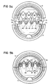
- Fig. 5a and Fig. 5b the two shells 5 and 6 are shown in a view of the sensor elements 2 and 3 ago, wherein the two shells 5 and 6 in Fig. 5a are not yet fully assembled in Fig. 5b ,
- FIG. 5 a the second row of teeth displaced to the rear relative to the first row of teeth is shown with dashed lines - thus invisibly marked - tooth tips of the teeth 27, 26 and 28.
- a tooth 27 or 26 or 28 is exactly behind a corresponding tooth 20 or 21 or 22, wherein the tooth tips of the first row of teeth are directed opposite to the tooth tips of the second row of teeth.
- the two shells 5 and 6 have positioning means by which the two shells 5 and 6 when mating against each other are precisely aligned.
- the second shell 6 has, for example, cams 70 and 71 which, when the two shells 5 and 6 are joined together, are inserted into corresponding holes 72 and 73 recessed on the first shell 5.
- a denotes the distance between the two adjacent lead wires 23 and 24 and b the Distance between the two adjacent leads 24 and 25.
- the distance a or b between two connecting wires is so small that could form on the surface of the two shells 5 and 6 unacceptably high leakage currents between the connecting wires 23 and 24 or 24 and 25, is advantageously at the two shells 5 and 6 design a surface shape such that a significant path for leakage currents is greater than the distance a or b between the connecting wires 23 and 24 or 24 and 25.
- a significant reduction of leakage currents can be achieved by forming a substantially frusto-conical structure 80, 81 and 82 at exit points of the connecting wires 23, 24, 25.
- the two shells 5 and 6 are advantageously matched to the diameter and the shape of the connecting wires 23, 24 and 25 such that a printed circuit board side on the two shells 5 and 6 applied sealant sensor side for creepage currents between the connecting wires 23, 24 and 25 decisive shaping of the guide means is not affected effectively.
- the two shells 5 and 6 are shown completely separated prior to assembly.
- the two shells 5 and 6 by a with Advantage side of the shells 5 and 6 arranged hinge connected to each other, wherein a rotation axis of the hinge is parallel to the lead wires 23, 24 and 25.
- the hinge is formed directly in the integral molding of the two shells 5 and 6.
- a measuring device shown in FIG. 6 has a capacitive humidity sensor 60 and a temperature sensor 61.
- An electrical signal S1 of the humidity sensor 60 is guided to form a humidity signal H with advantage on a connected to the humidity sensor 60 first transducer 62, while an electrical signal S2 of the temperature sensor 61 to form a temperature signal T with advantage on a connected to the temperature sensor 61 second Signal converter 63 is guided.
- the two transducers 62 and 63 are connected to a microprocessor 64.
- a data memory 65 has correction data K for correcting the humidity signal H.
- An output Hr corresponding to the detected relative humidity is calculable by the microprocessor 64 using the humidity signal H, the temperature signal T and the correction data K.
- the output signal Hr is conditioned in an interface unit 66 for a certain communication standard and provided as a standardized output signal Hrs.
- a change in an important sensor characteristic value is detected by a monitoring unit 67 over a relatively long period of time, that is to say over several months or years.
- a change in the ohmic resistance of the humidity sensor 60 is detected by the monitoring unit 67.
- a larger deviation of the resistance value of the capacitive humidity sensor 60 on indicate an error or advanced aging of the humidity sensor 60.
- a status signal ⁇ R is output at an output 68, which is evaluated or forwarded, for example, by the microprocessor 64.
- the status signal ⁇ R is forwarded, for example, as additional information with the output signal Hr or provided in a variant of the measuring device independently of the output signal Hr.
- the signal converters 62 and 63, the microprocessor 64, the data memory 65 are advantageously arranged on the printed circuit board 4 (FIG. 1).
- the interface unit 66 is accommodated on the printed circuit board 4 or in a variant on the side of the sensor tube 8 facing away from the printed circuit board 4 in a further housing.
Landscapes
- Physics & Mathematics (AREA)
- General Physics & Mathematics (AREA)
- Investigating Or Analyzing Materials By The Use Of Electric Means (AREA)
- Measuring Pulse, Heart Rate, Blood Pressure Or Blood Flow (AREA)
- Eye Examination Apparatus (AREA)
- Optical Transform (AREA)
Description
- Die Erfindung bezieht sich auf eine Messeinrichtung der im Oberbegriff des Anspruchs 1 genannten Art.
- Solche Messeinrichtungen werden vorteilhaft in der Heizungs-, Lüftungs- und Klimatechnik (HLK) für Gebäude zur Erfassung einer Prozessgrösse eingesetzt. Eine derartige Messeinrichtung ist beispielhaft eine Einrichtung zur Erfassung der Luftfeuchtigkeit in einem Raum oder in einer Einrichtung zum Zu- oder Abführen von Luft.
- Derartige Messeinrichtungen sind auch zur Erfassung der Beleuchtungsstärke oder zur Gasdetektion nutzbar.
- Die vorliegende Erfindung ist grundsätzlich einsetzbar, wenn Prozessgrössen mit Sensorelementen erfasst werden, die elektrische Anschlussdrähte aufweisen. Eine derartige Messeinrichtung ist also auch in einem Fahrzeug einsetzbar.
- Eine bekannte Messeinrichtung zur Erfassung der Luftfeuchtigkeit weist einen kapazitiven Feuchtesensor und einen Temperatursensor auf. Zur Erfassung von elektrischen Messsignalen sind Anschlussdrähte der beiden Sensoren über Steck- oder Lötverbindungen mit einer elektronischen Schaltung oder mit einem Anschlusskabel verbunden.
- Der Erfindung liegt die Aufgabe zu Grunde, eine Messeinrichtung mit elektrischen Sensoren zu schaffen, in der auch unisolierte dünne Anschlussdrähte eines Sensors - beispielsweise solche mit einem Drahtdurchmesser in der Grössenordnung von 0,1 mm - reproduzierbar, sicher und kostengünstig mit einer Leiterplatte verbindbar sind.
- Die genannte Aufgabe wird erfindungsgemäss durch die Merkmale des Anspruchs 1 gelöst. Vorteilhafte Ausgestaltungen ergeben sich aus den abhängigen Ansprüchen.
- Nachfolgend werden Ausführungsbeispiele der Erfindung anhand der Zeichnung näher erläutert.
-
- Fig. 1 eine Explosionsdarstellung einer Messeinrichtung mit einem Sensormodul,
- Fig. 2 das Sensormodul mit Teilen eines Führungsmittels für Anschlüsse von Sensorelementen,
- Fig. 3 ein Ausschnitt einer geschnittenen Darstellung des Sensormoduls,
- Fig. 4 eine Prinzipdarstellung zur Wirkungsweise des Führungsmittels,
- Fig. 5a eine Ansicht des Führungsmittels im Zustand der Montage,
- Fig. 5b eine weitere Ansicht des Führungsmittels im montierten Zustand,
- Fig. 6 ein Blockschaltbild der Messeinrichtung in einer Ausführung zur Erfassung der relativen Luftfeuchtigkeit.
- In der Fig. 1 bezeichnet 1 ein Sensormodul mit einem ersten Sensorelement 2 und einem zweiten Sensorelement 3, mit einer ein- oder mehrlagigen Leiterplatte 4, mit einer ersten Schale 5 und einer zweiten Schale 6.
- Beispielhaft ist das erste Sensorelement 2 ein Feuchtesensor und das zweite Sensorelement 3 ein Temperatursensor. Mit den beiden Sensorelementen 2 und 3 ist beispielsweise die relative Feuchte eines Raumes oder eines Luftkanals erfassbar.
- Für die vorliegende Erfindung ist es grundsätzlich nicht relevant, ob das Sensormodul 1 mehrere Sensorelemente oder lediglich ein einziges Sensorelement aufweist.
- Die beiden Schalen 5 und 6 sind derart ausgebildet, dass sie zusammengefügt eine Halterungsfunktion für das Sensormodul 1 ausüben.
- Bei Bedarf werden die Sensorelemente 2 und 3 durch eine Abdeckung oder durch ein Filter 7 geschützt, welche vorteilhafterweise über die beiden Schalen 5 und 6 am Sensormodul 1 befestigt werden.
- Insbesondere für den Einsatz in einem Kanalfühler ist die Leiterplatte 4 mit einem Fühlerrohr 8 abdeckbar, das vorteilhafterweise über die beiden Schalen 5 und 6 am Sensormodul 1 befestigt wird.
- Die Leiterplatte 4 ist beispielsweise über ein mit einem Stecker 9 versehenen Kabel mit einem übergeordneten System, typischerweise mit einem Regel- oder Steuergerät verbunden. In einer Variante ist auf der Leiterplatte 4 eine Kommunikationseinrichtung zur drahtlosen Datenübertragung zwischen dem Sensormodul und dem übergeordneten System angeordnet.
- Durch ihre Ausgestaltung dienen die beiden Schalen 5 und 6 in vorteilhafter Art und Weise bei der Montage des Sensormoduls 1 als Produktionswerkzeug. Mit Vorteil werden Formen der Leiterplatte 4 und der ersten Schale 5 so aufeinander abgestimmt, dass die Leiterplatte 4 wenigstens in einem Bereich 10, in dem die Sensorelemente 2 und 3 mit der Leiterplatte 4 zu kontaktieren sind, in der ersten Schale 5 gelagert wird. Ausserdem weisen die Schalen 5 und 6 und die Leiterplatte 4 aufeinander abgestimmte konstruktive Mittel auf, durch welche die Leitplatte 4 im montierten Zustand in den beiden Schalen 5 und 6 festgehalten ist.
- Zur Lagerung der Leiterplatte 4 weist die erste Schale 5 beispielhaft sich gegenüberliegende Absätze 11 auf, durch die die Positionierung der Leiterplatte 4 auf der ersten Schale 5 bestimmt wird. Zudem weist die erste Schale 5 beispielhaft Nocken 12 auf, welche in Verbindung mit an der Leiterplatte 4 ausgebildeten Ausnehmungen 13 die Leiterplatte 4 im montierten Zustand in den Schalen 4 und 5 festhalten.
- In der Fig. 2 ist die Leiterplatte 4 in der als Produktionswerkzeug einsetzbaren ersten Schale 5 gelagert, wobei die zweite Schale 6 in abgehobenem Zustand dargestellt ist.
- Ein erster Zahn 20, ein zweiter Zahn 21 und ein dritter Zahn 22 gehören zu einer ersten gegen die Sensorelemente 2 und 3 hin angeordneten Zahnreihe, welche vorteilhafterweise in der ersten Schale 5 ausgeformt ist und durch welche elektrische Anschlussdrähte 23, 24 und 25 der Sensorelemente 2 und 3 in einem gewissen Abstand voneinander isoliert zur Leiterplatte 4 geführt werden.
- Mit Vorteil werden die elektrischen Anschlussdrähte 23, 24 und 25 direkt mit der Leiterplatte 4 verlötet.
- In der Fig. 3 ist der zweite Zahn 21 in einem Schnitt dargestellt. Mit 26 ist ein vierter Zahn bezeichnet, der zu einer zweiten Zahnreihe gehört, welche gegenüber der ersten Zahnreihe gegen die Leiterplatte hin versetzt in der zweiten Schale 6 ausgeformt ist.
- Zum besseren Verständnis des durch die beiden Schalen 5 und 6 ermöglichten Montageverfahrens ist die in der ersten Schale 5 ausgebildete erste Zahnreihe und die in der zweiten Schale 6 ausgebildete zweite Zahnreihe auszugsweise und vereinfacht in der Fig. 4 dargestellt, wobei die beiden Schalen 5 und 6 noch nicht vollständig zusammengefügt sind, und die Ansicht von den Sensorelementen 2 und 3 her dargestellt ist. Neben dem vierten Zahn 26 weist die zweite Zahnreihe einen fünften Zahn 27 und einen sechsten Zahn 28 auf.
- Die in der ersten Schale 5 ausgebildete Zahnreihe mit den Zähnen 20, 21 und 22 und die in der zweiten Schale 6 ausgebildete Zahnreihe mit den Zähnen 26, 27 und 28, welche entgegengesetzt den Zähnen 20, 21 und 22 der erste Zahnreihe gerichtet sind, bilden ein zwischen der Leiterplatte 4 und den Sensorelementen 2 und 3 angeordnetes Führungsmittel, durch welches die elektrischen Anschlussdrähte 23, 24 und 25 in einem gewissen Abstand voneinander isoliert zur Leiterplatte 4 geführt werden.
- Das Führungsmittel ist in der genauen Formgebung und Auslegung in weiten Grenzen an sich stellenden Anforderungen anpassbar; so beispielsweise an Anzahl und Masse der eingesetzten Sensorelemente, an Form und Drahtdurchmesser der Anschlussdrähte, an eine geforderte Qualität der Abdichtung rund um die Anschlussdrähte und an eine geforderte Kriechstrom- oder auch Spannungsfestigkeit zwischen einzelnen Anschlussdrähten.
- Typischerweise sind die beiden Schalen 5 und 6 aus einem Kunststoff gefertigt, wobei insbesondere gewisse Thermoplaste vorteilhaft sind, die kaum Feuchtigkeit aufnehmen.
- Bei Bedarf sind zwischen dem montierten Führungsmittel und den Anschlussdrähten existierende Hohlräume durch ein Giessharz abgedichtet, das vorteilhafterweise von der Leiterplatte 4 her eingebracht wird.
- In einer vorteilhaften Ausführung sind die Zähne 20, 21, 22, 26, 27 und 28 im wesentlichen keilförmig ausgebildet. Die beiden Zahnreihen sind derart ausgebildet und angeordnet, dass ein erster einem ersten Anschlussdraht 23 zugeordneter Kanal 30 von zwei benachbarten Zähnen 20 und 21 der ersten Zahnreihe und von zwei benachbarten Zähnen 27 und 26 der zweiten Zahnreihe begrenzt wird. Ein zweiter einem zweiten Anschlussdraht 24 zugeordneter Kanal 31 wird von zwei weiteren benachbarten Zähnen 21 und 22 der ersten Zahnreihe und von zwei weiteren benachbarten Zähnen 26 und 28 der zweiten Zahnreihe begrenzt.
- Bei einem Zusammenfügen der beiden Schalen 5 und 6 verkleinern sich der Querschnitt des ersten Kanals 30 und auch der Querschnitt des zweiten Kanals 31 immer mehr, wobei der im ersten Kanal 30 eingelegte Anschlussdraht eingefangen und in einem zwischen dem ersten Zahn 20 und dem zweiten Zahn 21 ausgebildeten Sattel 32 positioniert wird und wobei auch der im zweiten Kanal 31 eingelegte Anschlussdraht eingefangen und in einem zwischen dem zweiten Zahn 21 und dem dritten Zahn 22 ausgebildeten weiteren Sattel 33 positioniert wird.
- Eine von einem Keilwinkel α der Zähne der zweiten Zahnreihe oder von einem Keilwinkel β der Zähne der ersten Zahnreihe abhängige Steilheit der Zahnflanken wird mindestens so steil gewählt, dass beim Einfangen der Anschlussdrähte 23 und 24 keine Selbsthemmung auftritt. Der zwischen benachbarten Zähnen einer Zahnreihe ausgeformte Sattel 32 oder 33 ist vorteilhafterweise derart auf die Form und den Durchmesser des aufgenommenen Anschlussdrahtes 23 bzw. 24 abgestimmt, dass ein gewisser Grad der Abdichtung, zwischen dem Sensorelement 2 oder 3 und der Leiterplatte im montierten Zustand der beiden zusammengefügten Schalen 5 und 6 erreicht wird.
- Bei Bedarf weist das Führungsmittel eine dritte Zahnreihe auf, welche zwischen der zweiten Zahnreihe und der Leiterplatte 4 angeordnet und an der ersten Schale 5 ausgebildet ist. Mit Vorteil weist die dritte Zahnreihe einen siebten Zahn 35 (Fig. 2), einen achten Zahn 36 und einen neunten Zahn 37 auf, wobei der Anschlussdraht 23 des ersten Sensorelements 2 zwischen dem siebten Zahn 35 und dem achten Zahn 36 liegt und der Anschlussdraht 24 des zweiten Sensorelements 3 zwischen dem achten Zahn 36 und dem neunten Zahn 37 liegt. Mit Vorteil sind die Zähne 35, 36 und 37 der dritten Zahnreihe von den Sensorelementen 2 und 3 aus gesehen genau hinter den entsprechenden Zähnen 20, 21 und 22 der ersten Zahnreihe angeordnet und die zweite Zahnreihe ist im zusammengefügten Zustand der beiden Schalen 5 und 6 zwischen der ersten und der dritten Zahnreihe eingefügt.
- In Fig. 5a und Fig. 5b sind die beiden Schalen 5 und 6 in einer Ansicht von den Sensorelementen 2 und 3 her dargestellt, wobei die beiden Schalen 5 und 6 in der Fig. 5a noch nicht und in der Fig. 5b vollständig zusammengefügt sind.
- In der Fig. 5a ist die gegenüber der ersten Zahnreihe nach hinten verschobene zweite Zahnreihe mit teilweise gestrichelt - also unsichtbar markiert - gezeichneten Zahnspitzen der Zähne 27, 26 und 28. Mit Vorteil ist ein Zahn 27 oder 26 oder 28 genau hinter einem entsprechenden Zahn 20 oder 21 oder 22 angeordnet, wobei die Zahnspitzen der ersten Zahnreihe entgegengesetzt zu den Zahnspitzen der zweiten Zahnreihe gerichtet sind.
- Vorteilhafterweise verfügen die beiden Schalen 5 und 6 über Positionierungsmittel, durch welche die beiden Schalen 5 und 6 beim Zusammenfügen gegeneinander genau ausrichtbar sind. Zur genauen Positionierung weist die zweite Schale 6 beispielhaft Nocken 70 und 71 auf, die bei Zusammenfügen der beiden Schalen 5 und 6 in entsprechende an der ersten Schale 5 ausgenommene Löcher 72 und 73 eingeführt werden.
- In der Fig. 5b bezeichnet a den Abstand zwischen den zwei nebeneinanderliegenden Anschlussdrähten 23 und 24 und b den Abstand zwischen den zwei nebeneinanderliegenden Anschlussdrähten 24 und 25.
- Sofern der Abstand a bzw. b zwischen zwei Anschlussdrähten so klein ist, dass sich an der Oberfläche der beiden Schalen 5 und 6 unzulässig hohe Kriechströme zwischen den Anschlussdrähten 23 und 24 bzw. 24 und 25 ausbilden könnten, wird vorteilhafterweise an den beiden Schalen 5 und 6 eine Oberflächenform derart gestaltet, dass ein für Kriechströme massgeblicher Weg grösser als der Abstand a bzw. b zwischen den Anschlussdrähten 23 und 24 bzw. 24 und 25 ist. Eine wesentliche Verminderung von Kriechströmen ist dadurch erreichbar, dass an Austrittstellen der Anschlussdrähte 23, 24, 25 je ein im wesentlichen zylinderstumpfförmiger Aufbau 80, 81 und 82 ausgeformt wird. Insbesondere in der isometrischen Darstellung der Fig. 2 ist sehr gut ersichtlich, dass beim zweiten Sensorelement 3 der für einen Kriechstrom massgebliche Weg zwischen den Anschlussdrähten 24 und 25, durch den an der Austrittsstelle des Anschlussdrahts 24 ausgebildete Aufbau 81 und den an der Austrittsstelle des Anschlussdrahts 25 ausgebildete Aufbau 82 wesentlich grösser ist, als der Abstand zwischen den beiden Anschlussdrähten 24 und 25.
- Sofern Dichtungsmasse verwendet wird, sind die beiden Schalen 5 und 6 vorteilhafterweise derart auf die Durchmesser und die Form der Anschlussdrähte 23, 24 und 25 abgestimmt, dass eine leiterplattenseitig an den beiden Schalen 5 und 6 aufgetragene Dichtungsmasse sensorseitig eine für Kriechströme zwischen den Anschlussdrähten 23, 24 und 25 massgebende Formgebung des Führungsmittels nicht wirksam beeinträchtigt wird.
- In den in der Zeichnung dargestellten Ausführungsbeispielen sind die beiden Schalen 5 und 6 vor dem Zusammenfügen vollständig getrennt dargestellt. In einer Variante des Sensormoduls 1 sind die beiden Schalen 5 und 6 durch ein mit Vorteil seitlich an den Schalen 5 und 6 angeordnetes Scharnier miteinander verbunden, wobei eine Drehachse des Scharniers parallel zu den Anschlussdrähten 23, 24 und 25 liegt. Beispielhaft wird das Scharnier direkt beim einstückigen Formen der beiden Schalen 5 und 6 ausgebildet.
- Eine in der Fig. 6 dargestellte Messeinrichtung weist einen kapazitiven Feuchtesensor 60 und einen Temperatursensor 61 auf. Ein elektrisches Signal S1 des Feuchtesensors 60 ist zur Bildung eines Feuchtesignals H mit Vorteil auf einen mit dem Feuchtesensor 60 verbundenen ersten Signalumformer 62 geführt, während ein elektrisches Signal S2 des Temperatursensors 61 zur Bildung eines Temperatursignals T mit Vorteil auf einen mit dem Temperatursensor 61 verbundenen zweiten Signalumformer 63 geführt ist. Ausgangsseitig sind die beiden Signalumformer 62 und 63 mit einem Mikroprozessor 64 verbunden.
- Ein Datenspeicher 65 weist Korrekturdaten K zur Korrektur des Feuchtesignals H auf. Ein der erfassten relativen Luftfeuchtigkeit entsprechendes Ausgangssignal Hr ist vom Mikroprozessor 64 unter Verwendung des Feuchtesignals H, des Temperatursignals T und der Korrekturdaten K berechenbar.
- Bei Bedarf wird das Ausgangssignal Hr in einer Schnittstelleneinheit 66 für einen gewissen Kommunikationsstandard aufbereitet und als standardisiertes Ausgangssignal Hrs zur Verfügung gestellt.
- In einer vorteilhaften Ausführung der Messeinrichtung wird eine Veränderung eines wichtigen Sensorkennwerts von einer Überwachungseinheit 67 über einen längeren Zeitraum, also über mehrere Monate oder Jahre erfasst. In der beispielhaften Ausführung nach der Fig. 6 wird eine Veränderung des ohmschen Widerstandes des Feuchtesensors 60 von der Überwachungseinheit 67 erfasst. Eine grössere Abweichung des Widerstandswertes des kapazitiven Feuchtesensors 60, kann auf einen Fehler oder auf eine fortgeschrittene Alterung des Feuchtesensors 60 hindeuten. Für eine Fehlerdiagnose wird an einem Ausgang 68 ein Zustandssignal ΔR ausgegeben, welches beispielsweise vom Mikroprozessor 64 ausgewertet oder weitergeleitet wird. Das Zustandssignal ΔR wird beispielsweise als zusätzliche Information mit dem Ausgangssignal Hr weitergeleitet oder in einer Variante der Messeinrichtung unabhängig vom Ausgangssignal Hr zur Verfügung gestellt.
- Die Signalumformer 62 und 63, der Mikroprozessor 64, der Datenspeicher 65 sind mit Vorteil auf der Leiterplatte 4 (Fig. 1) angeordnet. Die Schnittstelleneinheit 66 ist je nach Bedarf auf der Leiterplatte 4 oder in einer Variante auf der der Leiterplatte 4 abgewandten Seite des Fühlerrohrs 8 in einem weiteren Gehäuse untergebracht.
Claims (14)
- Sensormodul mit wenigstens einem elektrische Anschlussdrähte aufweisenden Sensorelement und einer Leiterplatte, wobei die elektrischen Anschlussdrähte des Sensorelements mit der Leiterplatte elektrisch leitend verbunden sind,
wobei ein zwischen der Leiterplatte (4) und dem Sensorelement (2; 3) angeordnetes Führungsmittel (20,21, 22, 26, 27, 28) verhanden ist durch welches die elektrischen Anschlussdrähte (23, 24, 25) in einem gewissen Abstand voneinander isoliert zur Leiterplatte (4) geführt werden,
wobei das Führungsmittel (20,21,22,26,27,28) ein erstes Teil und ein zweites Teil (26,27,28) aufweist und die Anschlussdrähte (23, 24, 25) zwischen dem ersten Teil (20,21,22) und dem zweiten Teil (26,27,28) angeordnet sind,
dadurch gekennzeichnet, dass das erste Teil (20,21,22) im wesentlichen keilförmige Zähne(20,21,22) aufweist, die derart ausgebildet und angeordnet sind, dass ein Anschlussdraht (23; 24; 25) zwischen zwei nebeneinander angeordneten Zähnen liegt, und
wobei das zweite Teil (26,27,28) im wesentlichen keilförmige Zähne (26,27,28) aufweist, die derart ausgebildet und angeordnet sind, dass der Anschlussdraht (23; 24; 25) zwischen zwei nebeneinander angeordneten Zähnen liegt, und
wobei die Zähne des ersten Teils (20,21,22) gegenüber den Zähnen des zweiten Teils (26,27,28) versetzt angeordnet sind. - Sensormodul nach Anspruch 1, dadurch gekennzeichnet, dass das Führungsmittel (20,21,22,26,27,28) an einer Austrittstelle eines Anschlussdrahtes eine Oberflächenform aufweist, durch welche ein für einen Kriechstrom massgeblicher Weg zwischen dem Anschlussdraht und einem weiteren Anschlussdraht grösser als der Abstand zwischen den beiden Anschlussdrähten ist.
- Sensormodul nach einem vorangehenden Anspruch, dadurch gekennzeichnet, dass zwei benachbarte Zähne (20, 21) des ersten Teils eine Lücke bilden, in welcher ein Anschlussdraht (23) gefangen ist, wobei ein Sattel (32) der Lücke, auf dem der Anschlussdraht (23) aufliegt, und von dem aus je eine Zahnflanke der beiden benachbarten Zähne (20, 21) ausgeht, in einer eine leitende Schicht der Leiterplatte (4) aufweisenden Ebene liegt.
- Sensormodul nach einem vorangehenden Anspruch, dadurch gekennzeichnet, dass das erste Teil (20,21,22) an einer ersten Schale (5) ausgebildet ist, und
dass das zweite Teil (26,27,28) an einer zweiten Schale (6) ausgebildet ist, wobei die Leiterplatte (4) wenigstens an einer der beiden Schalen (5; 6) befestigt ist. - Sensormodul nach einem vorangehenden Anspruch, dadurch gekennzeichnet, dass die Leiterplatte (4) in der ersten Schale (5) gelagert ist.
- Sensormodul nach einem vorangehenden Anspruch, dadurch gekennzeichnet, dass die Anschlussdrähte (23, 24, 25) des Sensorelements (2; 3) an der Leiterplatte (4) angelötet sind.
- Sensormodul nach einem vorangehenden Anspruch, dadurch gekennzeichnet, dass die beiden Schalen (5, 6) derart auf die Durchmesser und die Form der Anschlussdrähte (23, 24, 25) des Sensorelements (2; 3) angepasst sind, dass eine leiterplattenseitig an den beiden Schalen (5, 6) aufgetragene Dichtungsmasse sensorseitig eine für Kriechströme zwischen den Anschlussdrähten (23, 24, 25) massgebende Formgebung des Führungsmittels (20,21,22,26,27,28) nicht wesentlich beeinträchtigt.
- Sensormodul nach einem vorangehenden Anspruch, dadurch gekennzeichnet, dass auf der Leiterplatte (4) eine elektronische Schaltung (62; 63) zur Umformung von elektrischen Sensorsignalen angeordnet ist.
- Sensormodul nach einem vorangehenden Anspruch, dadurch gekennzeichnet, dass auf der Leiterplatte (4) eine Datenspeicher (65) mit Daten (K) zur Korrektur von elektrischen Sensorsignalen angeordnet ist.
- Sensormodul nach einem vorangehenden Anspruch, dadurch gekennzeichnet, dass auf der Leiterplatte (4) ein Prozessor (64) angeordnet ist, durch den Sensorsignale transformierbar sind.
- Sensormodul nach einem vorangehenden Anspruch, dadurch gekennzeichnet, dass das Sensorelement durch ein Filter (7) abdeckbar ist.
- Sensormodul nach einem vorangehenden Anspruch, dadurch gekennzeichnet, dass ein die Leiterplatte (4) abdeckendes Fühlerrohr (8) angeordnet ist.
- Sensormodul nach einem vorangehenden Anspruch, dadurch gekennzeichnet, dass das Sensorelement (2; 3) ein Feuchtesensor ist.
- Sensormodul nach einem vorangehenden Anspruch, dadurch gekennzeichnet, dass das Sensorelement (2; 3) ein Temperatursensor ist.
Priority Applications (4)
| Application Number | Priority Date | Filing Date | Title |
|---|---|---|---|
| DE502004001155T DE502004001155D1 (de) | 2004-03-15 | 2004-03-15 | Messeinrichtung |
| AT04006043T ATE335988T1 (de) | 2004-03-15 | 2004-03-15 | Messeinrichtung |
| EP04006043A EP1577648B1 (de) | 2004-03-15 | 2004-03-15 | Messeinrichtung |
| US11/080,676 US7345591B2 (en) | 2004-03-15 | 2005-03-15 | Measuring device |
Applications Claiming Priority (1)
| Application Number | Priority Date | Filing Date | Title |
|---|---|---|---|
| EP04006043A EP1577648B1 (de) | 2004-03-15 | 2004-03-15 | Messeinrichtung |
Publications (2)
| Publication Number | Publication Date |
|---|---|
| EP1577648A1 EP1577648A1 (de) | 2005-09-21 |
| EP1577648B1 true EP1577648B1 (de) | 2006-08-09 |
Family
ID=34833594
Family Applications (1)
| Application Number | Title | Priority Date | Filing Date |
|---|---|---|---|
| EP04006043A Expired - Lifetime EP1577648B1 (de) | 2004-03-15 | 2004-03-15 | Messeinrichtung |
Country Status (3)
| Country | Link |
|---|---|
| EP (1) | EP1577648B1 (de) |
| AT (1) | ATE335988T1 (de) |
| DE (1) | DE502004001155D1 (de) |
Cited By (1)
| Publication number | Priority date | Publication date | Assignee | Title |
|---|---|---|---|---|
| US9689719B2 (en) | 2014-10-29 | 2017-06-27 | Siemens Aktiengesellschaft | Cover for a duct sensor |
Families Citing this family (2)
| Publication number | Priority date | Publication date | Assignee | Title |
|---|---|---|---|---|
| EP4067182B1 (de) * | 2021-02-19 | 2024-06-12 | Transportation IP Holdings, LLC | Sensoranordnung, trockner und fahrzeugsteuerungssystem damit |
| US12344214B2 (en) | 2021-02-19 | 2025-07-01 | Transportation Ip Holdings, Llc | Sensor assembly, dryer, and vehicle control system using the same |
Family Cites Families (4)
| Publication number | Priority date | Publication date | Assignee | Title |
|---|---|---|---|---|
| DE4241242C2 (de) * | 1992-12-08 | 1995-01-19 | Honeywell Bv | Elektrischer Zustandsfühler |
| DE19719010C2 (de) * | 1996-05-24 | 2003-04-30 | Ifm Electronic Gmbh | Wärmeübergangskontroll- und/oder -meßgerät |
| DE19938868B4 (de) * | 1999-08-17 | 2005-11-24 | Siemens Ag | Sensoreinrichtung und Verfahren zum Herstellen einer Sensoreinrichtung |
| DE10146156A1 (de) * | 2000-09-20 | 2002-04-04 | Delphi Tech Inc | Modulare Sensoranordnung und Verfahren zur Herstellung derselben |
-
2004
- 2004-03-15 EP EP04006043A patent/EP1577648B1/de not_active Expired - Lifetime
- 2004-03-15 AT AT04006043T patent/ATE335988T1/de active
- 2004-03-15 DE DE502004001155T patent/DE502004001155D1/de not_active Expired - Lifetime
Cited By (1)
| Publication number | Priority date | Publication date | Assignee | Title |
|---|---|---|---|---|
| US9689719B2 (en) | 2014-10-29 | 2017-06-27 | Siemens Aktiengesellschaft | Cover for a duct sensor |
Also Published As
| Publication number | Publication date |
|---|---|
| ATE335988T1 (de) | 2006-09-15 |
| DE502004001155D1 (de) | 2006-09-21 |
| EP1577648A1 (de) | 2005-09-21 |
Similar Documents
| Publication | Publication Date | Title |
|---|---|---|
| DE19936300B4 (de) | Druckerkennungsvorrichtung und Druckerkennungsvorrichtung-Anordnung hiermit | |
| EP1202024B1 (de) | Sensormodul mit Blechformteil ( magnetoresistiver Drosselklappensensor ) | |
| EP2989669A1 (de) | Verfahren zum herstellen eines batterienkontaktierungssystems und batterienkontaktierungssystem | |
| DE10016843A1 (de) | Wärmeempfindlicher Flussratensensor | |
| EP1446643B1 (de) | Messfühler und messfühleranordnung | |
| DE112015002366T5 (de) | Elektronische drosselkörperanordnung | |
| DE112016004799T5 (de) | Leiterelementmodul und Batterieverbund | |
| DE102008006542A1 (de) | Batteriezustand-Detektorvorrichtung | |
| DE102007009569B4 (de) | Anschlusseinrichtung und Verfahren zu deren Herstellung | |
| EP3615903A1 (de) | Sensor zur erfassung eines räumlichen temperaturprofils und verfahren zur herstellung einer sensoreinheit | |
| EP4221966A1 (de) | Verfahren zur fertigung einer baugruppe aus einem kunststoff-schlauchabschnitt mit mindestens einer schlauch-drahteinlage und einem anschluss-konnektor | |
| WO2017194606A2 (de) | Vorrichtung zur temperaturregelung, verwendung der vorrichtung, verfahren zur herstellung eines gehäuses und gehäuse | |
| EP2893303A1 (de) | Ultraschallwandler und verfahren zur herstellung eines ultraschall-wandlers | |
| EP1577648B1 (de) | Messeinrichtung | |
| EP1797437B1 (de) | Gerät zum ermitteln von elektrischen grössen | |
| DE102013215145A1 (de) | Elektronisches Steuergerät | |
| DE10158529A1 (de) | Temperatur sensor | |
| DE102006019497A1 (de) | Sensorvorrichtung für eine Starterbatterie in einem Kraftfahrzeug | |
| EP2737326B1 (de) | Schaltung zum leiten eines elektrischen stromes | |
| DE102004056866A1 (de) | Extrudierte Flachleitung sowie Verfahren zum Erzeugen einer extrudierten Flachleitung | |
| DE112016000903B4 (de) | Motorvorrichtung | |
| DE102007018175A1 (de) | Stromverteiler für Leitungssatz inbesondere in einem Kraftfahrzeug | |
| WO2015014509A1 (de) | Mehrstufiges dichtsystem zum einsatz in einem kraftfahrzeugsteuergerät | |
| DE10158554B4 (de) | Temperatursensor | |
| DE102024115470A1 (de) | Drucksensor und herstellungsverfahren des drucksensors |
Legal Events
| Date | Code | Title | Description |
|---|---|---|---|
| PUAI | Public reference made under article 153(3) epc to a published international application that has entered the european phase |
Free format text: ORIGINAL CODE: 0009012 |
|
| AK | Designated contracting states |
Kind code of ref document: A1 Designated state(s): AT BE BG CH CY CZ DE DK EE ES FI FR GB GR HU IE IT LI LU MC NL PL PT RO SE SI SK TR |
|
| AX | Request for extension of the european patent |
Extension state: AL LT LV MK |
|
| RAP1 | Party data changed (applicant data changed or rights of an application transferred) |
Owner name: SIEMENS SCHWEIZ AG |
|
| 17P | Request for examination filed |
Effective date: 20051021 |
|
| GRAP | Despatch of communication of intention to grant a patent |
Free format text: ORIGINAL CODE: EPIDOSNIGR1 |
|
| AKX | Designation fees paid |
Designated state(s): AT BE BG CH CY CZ DE DK EE ES FI FR GB GR HU IE IT LI LU MC NL PL PT RO SE SI SK TR |
|
| GRAS | Grant fee paid |
Free format text: ORIGINAL CODE: EPIDOSNIGR3 |
|
| GRAA | (expected) grant |
Free format text: ORIGINAL CODE: 0009210 |
|
| AK | Designated contracting states |
Kind code of ref document: B1 Designated state(s): AT BE BG CH CY CZ DE DK EE ES FI FR GB GR HU IE IT LI LU MC NL PL PT RO SE SI SK TR |
|
| PG25 | Lapsed in a contracting state [announced via postgrant information from national office to epo] |
Ref country code: IT Free format text: LAPSE BECAUSE OF FAILURE TO SUBMIT A TRANSLATION OF THE DESCRIPTION OR TO PAY THE FEE WITHIN THE PRESCRIBED TIME-LIMIT;WARNING: LAPSES OF ITALIAN PATENTS WITH EFFECTIVE DATE BEFORE 2007 MAY HAVE OCCURRED AT ANY TIME BEFORE 2007. THE CORRECT EFFECTIVE DATE MAY BE DIFFERENT FROM THE ONE RECORDED. Effective date: 20060809 Ref country code: SK Free format text: LAPSE BECAUSE OF FAILURE TO SUBMIT A TRANSLATION OF THE DESCRIPTION OR TO PAY THE FEE WITHIN THE PRESCRIBED TIME-LIMIT Effective date: 20060809 Ref country code: IE Free format text: LAPSE BECAUSE OF FAILURE TO SUBMIT A TRANSLATION OF THE DESCRIPTION OR TO PAY THE FEE WITHIN THE PRESCRIBED TIME-LIMIT Effective date: 20060809 Ref country code: SI Free format text: LAPSE BECAUSE OF FAILURE TO SUBMIT A TRANSLATION OF THE DESCRIPTION OR TO PAY THE FEE WITHIN THE PRESCRIBED TIME-LIMIT Effective date: 20060809 Ref country code: NL Free format text: LAPSE BECAUSE OF FAILURE TO SUBMIT A TRANSLATION OF THE DESCRIPTION OR TO PAY THE FEE WITHIN THE PRESCRIBED TIME-LIMIT Effective date: 20060809 Ref country code: RO Free format text: LAPSE BECAUSE OF FAILURE TO SUBMIT A TRANSLATION OF THE DESCRIPTION OR TO PAY THE FEE WITHIN THE PRESCRIBED TIME-LIMIT Effective date: 20060809 Ref country code: FI Free format text: LAPSE BECAUSE OF FAILURE TO SUBMIT A TRANSLATION OF THE DESCRIPTION OR TO PAY THE FEE WITHIN THE PRESCRIBED TIME-LIMIT Effective date: 20060809 Ref country code: PL Free format text: LAPSE BECAUSE OF FAILURE TO SUBMIT A TRANSLATION OF THE DESCRIPTION OR TO PAY THE FEE WITHIN THE PRESCRIBED TIME-LIMIT Effective date: 20060809 Ref country code: CZ Free format text: LAPSE BECAUSE OF FAILURE TO SUBMIT A TRANSLATION OF THE DESCRIPTION OR TO PAY THE FEE WITHIN THE PRESCRIBED TIME-LIMIT Effective date: 20060809 |
|
| REG | Reference to a national code |
Ref country code: GB Ref legal event code: FG4D Free format text: NOT ENGLISH |
|
| REG | Reference to a national code |
Ref country code: CH Ref legal event code: EP |
|
| REG | Reference to a national code |
Ref country code: IE Ref legal event code: FG4D Free format text: LANGUAGE OF EP DOCUMENT: GERMAN |
|
| REF | Corresponds to: |
Ref document number: 502004001155 Country of ref document: DE Date of ref document: 20060921 Kind code of ref document: P |
|
| PG25 | Lapsed in a contracting state [announced via postgrant information from national office to epo] |
Ref country code: DK Free format text: LAPSE BECAUSE OF FAILURE TO SUBMIT A TRANSLATION OF THE DESCRIPTION OR TO PAY THE FEE WITHIN THE PRESCRIBED TIME-LIMIT Effective date: 20061109 Ref country code: BG Free format text: LAPSE BECAUSE OF FAILURE TO SUBMIT A TRANSLATION OF THE DESCRIPTION OR TO PAY THE FEE WITHIN THE PRESCRIBED TIME-LIMIT Effective date: 20061109 |
|
| PG25 | Lapsed in a contracting state [announced via postgrant information from national office to epo] |
Ref country code: ES Free format text: LAPSE BECAUSE OF FAILURE TO SUBMIT A TRANSLATION OF THE DESCRIPTION OR TO PAY THE FEE WITHIN THE PRESCRIBED TIME-LIMIT Effective date: 20061120 |
|
| GBT | Gb: translation of ep patent filed (gb section 77(6)(a)/1977) |
Effective date: 20061030 |
|
| REG | Reference to a national code |
Ref country code: SE Ref legal event code: TRGR |
|
| PG25 | Lapsed in a contracting state [announced via postgrant information from national office to epo] |
Ref country code: PT Free format text: LAPSE BECAUSE OF FAILURE TO SUBMIT A TRANSLATION OF THE DESCRIPTION OR TO PAY THE FEE WITHIN THE PRESCRIBED TIME-LIMIT Effective date: 20070109 |
|
| NLV1 | Nl: lapsed or annulled due to failure to fulfill the requirements of art. 29p and 29m of the patents act | ||
| ET | Fr: translation filed | ||
| REG | Reference to a national code |
Ref country code: IE Ref legal event code: FD4D |
|
| PLBE | No opposition filed within time limit |
Free format text: ORIGINAL CODE: 0009261 |
|
| STAA | Information on the status of an ep patent application or granted ep patent |
Free format text: STATUS: NO OPPOSITION FILED WITHIN TIME LIMIT |
|
| 26N | No opposition filed |
Effective date: 20070510 |
|
| BERE | Be: lapsed |
Owner name: SIEMENS SCHWEIZ A.G. Effective date: 20070331 |
|
| PG25 | Lapsed in a contracting state [announced via postgrant information from national office to epo] |
Ref country code: BE Free format text: LAPSE BECAUSE OF NON-PAYMENT OF DUE FEES Effective date: 20070331 |
|
| PG25 | Lapsed in a contracting state [announced via postgrant information from national office to epo] |
Ref country code: MC Free format text: LAPSE BECAUSE OF NON-PAYMENT OF DUE FEES Effective date: 20070331 |
|
| PG25 | Lapsed in a contracting state [announced via postgrant information from national office to epo] |
Ref country code: GR Free format text: LAPSE BECAUSE OF FAILURE TO SUBMIT A TRANSLATION OF THE DESCRIPTION OR TO PAY THE FEE WITHIN THE PRESCRIBED TIME-LIMIT Effective date: 20061110 |
|
| PG25 | Lapsed in a contracting state [announced via postgrant information from national office to epo] |
Ref country code: EE Free format text: LAPSE BECAUSE OF FAILURE TO SUBMIT A TRANSLATION OF THE DESCRIPTION OR TO PAY THE FEE WITHIN THE PRESCRIBED TIME-LIMIT Effective date: 20060809 |
|
| REG | Reference to a national code |
Ref country code: FR Ref legal event code: TP |
|
| REG | Reference to a national code |
Ref country code: CH Ref legal event code: NV Representative=s name: SIEMENS SCHWEIZ AG Ref country code: CH Ref legal event code: PUE Owner name: SIEMENS AKTIENGESELLSCHAFT Free format text: SIEMENS SCHWEIZ AG#ALBISRIEDERSTRASSE 245#8047 ZUERICH (CH) -TRANSFER TO- SIEMENS AKTIENGESELLSCHAFT#WITTELSBACHERPLATZ 2#80333 MUENCHEN (DE) |
|
| REG | Reference to a national code |
Ref country code: GB Ref legal event code: 732E Free format text: REGISTERED BETWEEN 20090514 AND 20090520 |
|
| PG25 | Lapsed in a contracting state [announced via postgrant information from national office to epo] |
Ref country code: CY Free format text: LAPSE BECAUSE OF FAILURE TO SUBMIT A TRANSLATION OF THE DESCRIPTION OR TO PAY THE FEE WITHIN THE PRESCRIBED TIME-LIMIT Effective date: 20060809 Ref country code: LU Free format text: LAPSE BECAUSE OF NON-PAYMENT OF DUE FEES Effective date: 20070315 |
|
| PG25 | Lapsed in a contracting state [announced via postgrant information from national office to epo] |
Ref country code: HU Free format text: LAPSE BECAUSE OF FAILURE TO SUBMIT A TRANSLATION OF THE DESCRIPTION OR TO PAY THE FEE WITHIN THE PRESCRIBED TIME-LIMIT Effective date: 20070210 Ref country code: TR Free format text: LAPSE BECAUSE OF FAILURE TO SUBMIT A TRANSLATION OF THE DESCRIPTION OR TO PAY THE FEE WITHIN THE PRESCRIBED TIME-LIMIT Effective date: 20060809 |
|
| PG25 | Lapsed in a contracting state [announced via postgrant information from national office to epo] |
Ref country code: DE Free format text: LAPSE BECAUSE OF NON-PAYMENT OF DUE FEES Effective date: 20111001 |
|
| REG | Reference to a national code |
Ref country code: CH Ref legal event code: PUE Owner name: SIEMENS SCHWEIZ AG, CH Free format text: FORMER OWNER: SIEMENS AKTIENGESELLSCHAFT, DE |
|
| REG | Reference to a national code |
Ref country code: FR Ref legal event code: PLFP Year of fee payment: 12 |
|
| REG | Reference to a national code |
Ref country code: GB Ref legal event code: 732E Free format text: REGISTERED BETWEEN 20150220 AND 20150225 |
|
| REG | Reference to a national code |
Ref country code: DE Ref legal event code: R081 Ref document number: 502004001155 Country of ref document: DE Owner name: SIEMENS SCHWEIZ AG, CH Free format text: FORMER OWNER: SIEMENS AKTIENGESELLSCHAFT, 80333 MUENCHEN, DE Effective date: 20150407 |
|
| REG | Reference to a national code |
Ref country code: AT Ref legal event code: PC Ref document number: 335988 Country of ref document: AT Kind code of ref document: T Owner name: SIEMENS SCHWEIZ AG, CH Effective date: 20150330 |
|
| REG | Reference to a national code |
Ref country code: FR Ref legal event code: TP Owner name: SIEMENS SCHWEIZ AG, CH Effective date: 20160202 |
|
| REG | Reference to a national code |
Ref country code: FR Ref legal event code: PLFP Year of fee payment: 13 |
|
| REG | Reference to a national code |
Ref country code: FR Ref legal event code: PLFP Year of fee payment: 14 |
|
| REG | Reference to a national code |
Ref country code: FR Ref legal event code: PLFP Year of fee payment: 15 |
|
| PGFP | Annual fee paid to national office [announced via postgrant information from national office to epo] |
Ref country code: FR Payment date: 20230317 Year of fee payment: 20 Ref country code: AT Payment date: 20230207 Year of fee payment: 20 |
|
| PGFP | Annual fee paid to national office [announced via postgrant information from national office to epo] |
Ref country code: SE Payment date: 20230307 Year of fee payment: 20 Ref country code: IT Payment date: 20230321 Year of fee payment: 20 Ref country code: DE Payment date: 20220620 Year of fee payment: 20 |
|
| PGFP | Annual fee paid to national office [announced via postgrant information from national office to epo] |
Ref country code: CH Payment date: 20230612 Year of fee payment: 20 |
|
| PGFP | Annual fee paid to national office [announced via postgrant information from national office to epo] |
Ref country code: GB Payment date: 20230403 Year of fee payment: 20 |
|
| REG | Reference to a national code |
Ref country code: DE Ref legal event code: R071 Ref document number: 502004001155 Country of ref document: DE Ref country code: CH Ref legal event code: PL |
|
| REG | Reference to a national code |
Ref country code: GB Ref legal event code: PE20 Expiry date: 20240314 |
|
| PG25 | Lapsed in a contracting state [announced via postgrant information from national office to epo] |
Ref country code: GB Free format text: LAPSE BECAUSE OF EXPIRATION OF PROTECTION Effective date: 20240314 |
|
| REG | Reference to a national code |
Ref country code: SE Ref legal event code: EUG |
|
| REG | Reference to a national code |
Ref country code: AT Ref legal event code: MK07 Ref document number: 335988 Country of ref document: AT Kind code of ref document: T Effective date: 20240315 |