EP3018275A1 - Carriage assembly of a fitting for lifting and sliding doors or windows - Google Patents
Carriage assembly of a fitting for lifting and sliding doors or windows Download PDFInfo
- Publication number
- EP3018275A1 EP3018275A1 EP15190598.1A EP15190598A EP3018275A1 EP 3018275 A1 EP3018275 A1 EP 3018275A1 EP 15190598 A EP15190598 A EP 15190598A EP 3018275 A1 EP3018275 A1 EP 3018275A1
- Authority
- EP
- European Patent Office
- Prior art keywords
- coupling rod
- receptacle
- movement
- carriage assembly
- positive
- Prior art date
- Legal status (The legal status is an assumption and is not a legal conclusion. Google has not performed a legal analysis and makes no representation as to the accuracy of the status listed.)
- Granted
Links
- 230000008878 coupling Effects 0.000 claims abstract description 135
- 238000010168 coupling process Methods 0.000 claims abstract description 135
- 238000005859 coupling reaction Methods 0.000 claims abstract description 135
- 238000006073 displacement reaction Methods 0.000 claims abstract description 4
- 238000003780 insertion Methods 0.000 claims description 6
- 230000037431 insertion Effects 0.000 claims description 6
- 230000005484 gravity Effects 0.000 description 4
- 238000004519 manufacturing process Methods 0.000 description 3
- 230000002411 adverse Effects 0.000 description 1
- 230000005540 biological transmission Effects 0.000 description 1
- 238000009434 installation Methods 0.000 description 1
- 230000000149 penetrating effect Effects 0.000 description 1
- 230000000630 rising effect Effects 0.000 description 1
Images

Classifications
-
- E—FIXED CONSTRUCTIONS
- E05—LOCKS; KEYS; WINDOW OR DOOR FITTINGS; SAFES
- E05D—HINGES OR SUSPENSION DEVICES FOR DOORS, WINDOWS OR WINGS
- E05D15/00—Suspension arrangements for wings
- E05D15/56—Suspension arrangements for wings with successive different movements
- E05D15/565—Suspension arrangements for wings with successive different movements for raising wings before sliding
-
- E—FIXED CONSTRUCTIONS
- E05—LOCKS; KEYS; WINDOW OR DOOR FITTINGS; SAFES
- E05D—HINGES OR SUSPENSION DEVICES FOR DOORS, WINDOWS OR WINGS
- E05D15/00—Suspension arrangements for wings
- E05D15/06—Suspension arrangements for wings for wings sliding horizontally more or less in their own plane
- E05D15/0621—Details, e.g. suspension or supporting guides
- E05D15/066—Details, e.g. suspension or supporting guides for wings supported at the bottom
- E05D15/0665—Details, e.g. suspension or supporting guides for wings supported at the bottom on wheels with fixed axis
-
- E—FIXED CONSTRUCTIONS
- E05—LOCKS; KEYS; WINDOW OR DOOR FITTINGS; SAFES
- E05Y—INDEXING SCHEME ASSOCIATED WITH SUBCLASSES E05D AND E05F, RELATING TO CONSTRUCTION ELEMENTS, ELECTRIC CONTROL, POWER SUPPLY, POWER SIGNAL OR TRANSMISSION, USER INTERFACES, MOUNTING OR COUPLING, DETAILS, ACCESSORIES, AUXILIARY OPERATIONS NOT OTHERWISE PROVIDED FOR, APPLICATION THEREOF
- E05Y2201/00—Constructional elements; Accessories therefor
- E05Y2201/60—Suspension or transmission members; Accessories therefor
- E05Y2201/622—Suspension or transmission members elements
- E05Y2201/64—Carriers
-
- E—FIXED CONSTRUCTIONS
- E05—LOCKS; KEYS; WINDOW OR DOOR FITTINGS; SAFES
- E05Y—INDEXING SCHEME ASSOCIATED WITH SUBCLASSES E05D AND E05F, RELATING TO CONSTRUCTION ELEMENTS, ELECTRIC CONTROL, POWER SUPPLY, POWER SIGNAL OR TRANSMISSION, USER INTERFACES, MOUNTING OR COUPLING, DETAILS, ACCESSORIES, AUXILIARY OPERATIONS NOT OTHERWISE PROVIDED FOR, APPLICATION THEREOF
- E05Y2201/00—Constructional elements; Accessories therefor
- E05Y2201/60—Suspension or transmission members; Accessories therefor
- E05Y2201/622—Suspension or transmission members elements
- E05Y2201/686—Rods, links
-
- E—FIXED CONSTRUCTIONS
- E05—LOCKS; KEYS; WINDOW OR DOOR FITTINGS; SAFES
- E05Y—INDEXING SCHEME ASSOCIATED WITH SUBCLASSES E05D AND E05F, RELATING TO CONSTRUCTION ELEMENTS, ELECTRIC CONTROL, POWER SUPPLY, POWER SIGNAL OR TRANSMISSION, USER INTERFACES, MOUNTING OR COUPLING, DETAILS, ACCESSORIES, AUXILIARY OPERATIONS NOT OTHERWISE PROVIDED FOR, APPLICATION THEREOF
- E05Y2600/00—Mounting or coupling arrangements for elements provided for in this subclass
- E05Y2600/50—Mounting methods; Positioning
- E05Y2600/52—Toolless
- E05Y2600/528—Hooking, e.g. using bayonets; Locking
-
- E—FIXED CONSTRUCTIONS
- E05—LOCKS; KEYS; WINDOW OR DOOR FITTINGS; SAFES
- E05Y—INDEXING SCHEME ASSOCIATED WITH SUBCLASSES E05D AND E05F, RELATING TO CONSTRUCTION ELEMENTS, ELECTRIC CONTROL, POWER SUPPLY, POWER SIGNAL OR TRANSMISSION, USER INTERFACES, MOUNTING OR COUPLING, DETAILS, ACCESSORIES, AUXILIARY OPERATIONS NOT OTHERWISE PROVIDED FOR, APPLICATION THEREOF
- E05Y2900/00—Application of doors, windows, wings or fittings thereof
- E05Y2900/10—Application of doors, windows, wings or fittings thereof for buildings or parts thereof
- E05Y2900/13—Type of wing
- E05Y2900/148—Windows
- E05Y2900/15—Balcony glazing
Definitions
- the invention relates to a carriage assembly of a fitting for lifting-sliding doors or windows, with at least two carriages, each having at least one bearing for attachment to a wing of the door or the window and at least one support element with rollers for a running rail, which with the bearing is connected via lifting means which cause a lifting of the bearing relative to the support element in a direction perpendicular to the carriage longitudinal direction with a displacement of the support element in the carriage longitudinal direction by an actuating element, and with at least one the support elements of at least two carriages interconnecting coupling rod and at least one End of each support element in the longitudinal direction aligned recordings for insertion of the coupling rod as the first direction of movement.
- the coupling rod is circular in cross section.
- the coupling rod is aligned in the longitudinal extent of the support elements and introduced into receptacles in the support elements with the same or approximately the same cross section.
- the support elements have perpendicular to the Aufnahehlijnserstreck arranged threaded holes to fix the round coupling rod in the receptacle each by a screw frictionally.
- wear or the like in the longitudinal extent of the Coupling rod is to be expected with high forces, this fixation of the coupling rod in the support elements is often not sufficient.
- even a slight loosening of the screw enough to greatly affect the function of the carriage assembly. This can damage the entire hardware of the lift-and-slide doors or windows.
- the object is to improve the coupling of the support elements of the carriage with the coupling rod so far that in a simple manner a secure connection of the two components is made, which can transmit high forces.
- the coupling rod and the support element can be coupled together by positive locking elements, wherein the positive locking elements are arranged on a longitudinal surface of the coupling rod and in the receptacle of the support member and the positive locking element of the coupling rod in the receptacle by a second direction of movement of the coupling rod can penetrate into the receiving-side positive locking element and occupies a coupling position. From lift and slide doors and windows and thus also from the fitting a very long service life is expected. The opposite show the wings on a very high weight. Since the carriage in a mounted lift-slide door or a window are not readily accessible, a repair is very expensive.
- the positive connection between the support element and the coupling rod produced by the interlocking elements is therefore much safer than the non-positive fixing by a screw and transmits easily even under the most adverse conditions permanently very high tensile and compressive forces. Even with a game between the two components, for example, by constant vibrations, caused by the movements of the wing of the lift-slide door or window, the positive locking elements continue to ensure safe operation.
- the arrangement of the positive locking elements on a longitudinal surface of the coupling rod and the receptacle of the support element leads to a simple production. By moving the coupling rod in the receptacle in the second direction of movement, the positive connection is made particularly simple.
- Another improvement according to the invention is when at least at the ends of a longitudinal surface of the coupling rod as a form-fitting surface at least one cross-toothing is incorporated, which can be introduced into a receiving-side counter-toothing.
- the cross-toothing particularly high forces can be transmitted in a form-fitting manner in the longitudinal direction and a length compensation by a tooth offset between the coupling rod and the receptacle is possible with multiple teeth. This leads to a simple and flexible installation.
- the longitudinal edges of the longitudinal surface limit the cross-toothing.
- the cross-toothing is incorporated in the coupling rod. This allows a simple production of the cross teeth on the coupling rod. Elaborate material shifts beyond the cross-sectional circumference of the coupling rod addition or an additional component for the cross-toothing are not required.
- the receptacle in the support element in the cross-section is circumferentially closed and in the direction perpendicular to the positive locking surface of the positive locking element to the height of the positive locking element greater height H 1 than the corresponding height H 2 of the coupling rod during the movement in the first direction of movement in the recording. Due to the greater height H 1 of the recording, the coupling rod in the first direction of movement in the longitudinal direction of the support element are introduced along the receiving-side positive-locking element. Due to the second direction of movement of the coupling rod in the receptacle, the interlocking elements are joined together.
- the support member in the region of the receptacle for the assembly of the coupling rod, for example by a cover in several parts, since the coupling rod can be inserted despite the form-fitting elements in the circumferentially closed in cross section recording.
- the recording can be carried out inexpensively by the closed mold, transmit very high forces and protects the interlocking surfaces reliably.
- a variant of the invention provides that the second direction of movement of the coupling rod is a movement in the receptacle perpendicular to the first direction of movement in the direction of the receiving-side positive-locking element.
- the form-fitting elements come by moving the coupling rod into engagement.
- the cover guides the coupling rod by its cross-sectionally closed shape. This allows a simple and secure joining of the positive locking elements.
- a further embodiment according to the invention provides that the coupling rod-side positive-locking element is held by a fixing element in the receiving-side positive-locking element.
- the fixing element secures only the coupling position of the positive locking elements.
- the tensile and compressive forces to be transmitted by the coupling rod to the supporting elements are absorbed by the positive-locking elements. Therefore, the fixing element does not have to be made particularly stable.
- Another variant of the invention provides that the second direction of movement of the coupling rod is a rotational movement in the receptacle by about 90 °.
- the coupling rod is hereby rotated about its longitudinal axis and not further shifted elsewhere.
- the coupling rod-side positive-locking element is inserted during the rotation in the receiving-side positive-locking element. This has the advantage that a fixing element is not required. Only the frictional forces can then hold the coupling rod with appropriate design in the coupling position.
- This variant also allows a simple joining of the positive locking elements and an additional component for fixing the coupling
- a further embodiment of the invention provides that the fixing element is arranged on the support element opposite to the side of the positive locking element of the receptacle and can move into the receptacle into it.
- the fixing element is designed so that it prevents displacement of the coupling rod against the second direction of movement by penetrating into the free gap in the receptacle, which is caused by the movement of the coupling rod in the second direction of movement and thereby the coupling rod securely in the coupling position holds.
- the fixation of the coupling rod in the coupling position can be particularly easily performed when the fixing element is formed by a bolt having at least one perpendicular projecting from the axial direction retaining lug and is longitudinally displaceable in the direction of receiving, wherein the retaining lug for securing the coupling rod in the Coupling position can be screwed into tragelement facede Bolzenaus traditions.
- the fixing element is formed by a bolt having at least one perpendicular projecting from the axial direction retaining lug and is longitudinally displaceable in the direction of receiving, wherein the retaining lug for securing the coupling rod in the Coupling position can be screwed intooulement workede BolzenausEnglish Institute.
- no thread is required and the coupling position of the coupling rod is secured in a sufficient manner. Since only a 90 ° rotation of the fixing is required, the fixation is compared to a screw fixation particularly fast.
- a further advantageous embodiment of the carriage assembly according to the invention provides that the fixing element is formed by a pivotably mounted on the receptacle nose, which releases the recording by pivoting during insertion of the coupling rod in the first direction of movement and after the movement of the coupling rod in the second direction of movement, the coupling position guaranteed.
- the fixing element pivots when inserting the coupling rod in the first direction of movement in a recess of the receptacle and thereby releases the receptacle for the coupling element.
- the nose on the coupling rod during insertion facing side has a smooth surface and is rounded.
- the nose pivots into the space released there in the receptacle and thereby prevents a return movement of the coupling rod out of the coupling position.
- the pivotably mounted nose can swing out by gravity or by bias in the direction of the coupling rod.
- the coupling rod after swiveling touching surface can be performed with a rough surface and / or the nose is in a dead center position.
- the nose is secured against pivoting back.
- the pivoting back of the nose from the secured position can be done by a tool or by a not shown, easily accessible lever on the fixing.
- the carriage assembly is designed to be particularly flexible when the positive locking elements of the receptacle extend over the entire length of the receptacle and the Form-fitting elements of the coupling rod extend at least over this length.
- the coupling rod either completely or only partially inserted into the receptacle and then can be fixed in this position after the second direction of movement. Since several positive locking elements are always coupled in the coupling position, a secure transmission of high tensile and compressive forces is ensured. It is also possible that the positive locking elements of the coupling rod extend over the entire length of the coupling rod. This can mean a simplification in the production, at least for quite short coupling rods.
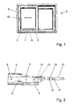
- FIG. 1 shows a lift-slide door 2 with a sliding movable wing 5, which is in a closed, lowered position.
- a carriage assembly 1 Via an actuating element 10, a carriage assembly 1 can be driven electrically or mechanically, which causes a lifting of the wing 5 in a direction perpendicular to the horizontal carriage longitudinal direction. After lifting the wing 5 this can be moved horizontally.
- the carriage assembly 1 is hidden in the lower, horizontal wing spar arranged and consists of two carriages 3, which are interconnected by a coupling rod 11.
- FIG. 2 shows a part of the carriage assembly 1 of Figure 1.
- a roller 7 which is rotatably supported and held on a support member 6.
- the support element 6 is connected via a lifting means 9 to the bearing 4.
- the bearing 4 is used for attachment to the in FIG. 1 illustrated wing 5 of the door or window and is shown here in the raised position relative to the support member 6, since it was moved by the lifting means 9 in a direction perpendicular to the carriage longitudinal direction and away from the running rail 8.
- the lifting means 9 may be a positive guide, consisting for example of a arranged on the support member 6 bolt, which is guided in an arranged in the bearing 4, obliquely rising scenery.
- a receptacle 12 for the coupling rod 11 is arranged concealed.
- the receptacle 12 has a height H 1 , which is greater than the height H 2 of the coupling rod 11 shown at least by the height of the coupling rod 11. This allows a sliding along the form-locking elements 13 of the coupling rod 11 to the form-locking elements 13 in the receptacle 12 in the first direction of movement 17 of the coupling rod 11 in which it is inserted into the receptacle 12. After the movement of the coupling rod 11 in the first Movement direction in the receptacle 12, the form-locking elements 13 are joined together by the movement of the coupling rod 11 in the second direction of movement 18.
- the positive locking elements 13 of the receptacle 12 and the coupling rod 11 have an equal length in the longitudinal direction, which corresponds to the length of the receptacle 12. It is not absolutely necessary during the movement of the coupling rod 11 in the first direction of movement to introduce the coupling rod 11 up to the end of the receptacle 12, since the form-locking elements 13 on both components consist of a multiplicity of identical teeth.
- the Figures 3.1 to 3.3 show a variant of the carriage arrangement 1 according to the invention with pivotable fixing element 19 in detail and the relevant components.
- the form-locking elements 13,23 are preferably arranged in this variant on the underside of the receptacle 12 and the coupling rod 11.
- the coupling rod 11 is rectangular in cross-section and therefore has four longitudinal surfaces 16.
- the receptacle 12 is shaped accordingly but has over the coupling rod 11 to the height of the positive locking element 23 increased height H 1 .
- Figure 3.1 is the coupling rod 11 outside the front of the recording 12. Now it is necessary to introduce the coupling rod 11 by the longitudinal movement in the first direction of movement 17 in the receptacle 12.
- the fixing element 19 is formed by a pivotably mounted nose 22 at the top of the receptacle 12.
- the Figure 3.2 shows the variant during the insertion of the coupling rod 11 in the receptacle 12, wherein the coupling rod 11 just pivots the projecting into the receptacle 12 nose 22 of the fixing element 19 against a biasing force and / or gravity, not shown.
- the nose 22 is to fully swing a recess in the recording 12 provided. As a result, the coupling rod 11 can be easily inserted into the receptacle 12.
- Figure 3.3 shows the variant in the secure coupling position in which the coupling rod 11 has been moved in this case by gravity almost independently in the second direction of movement and has ensured the positive connection with the receptacle 12 through the form-locking elements 13, 23.
- the nose 22 of the fixing element 19 is thereby pivoted back simultaneously in the direction of the coupling rod 11 and has been set against this and is in a dead center position.
- the pivoting of the fixing element 19 with the nose 22 can be done solely by gravity or additionally by a bias that moves the nose 22 toward the opening of the receptacle 12.
- FIGs 4.1 to 4.4 show a variant of the carriage assembly 1 according to the invention with a rotatable, bolt-like fixing element 19 in detail and the relevant components.
- the region of the support element 6 is shown partially cut.
- the interlocking elements 13,23 are preferably arranged in this variant at the top of the receptacle 12 and the coupling rod 11, the fixing element 19 can be actuated from the underside of the support element 6.
- the coupling rod 11 is rectangular in cross-section and therefore has four longitudinal surfaces 16.
- the receptacle 12 is shaped accordingly but has over the coupling rod 11 to the height of the positive locking element 23 increased height H 1 .
- Figure 4.1 is the coupling rod 11 outside the front of the recording 12.
- the fixing element 19 is formed by a bolt 20, which is longitudinally displaceable in the support element 6 and longitudinally displaceable at least 90 ° guided and accessible from the underside of the support element 6.
- the bolt 20 has at its end at least one perpendicular projecting from the axial direction retaining lug 25.
- the retaining lug 25 ideally has a height in the axial direction of the bolt, which corresponds to the gap in the receptacle with the coupling rod 11 in the coupling position.
- Figure 4.2 shows the variant with inserted coupling rod 11.
- FIGS 5.1 to 5.3 show a variant of the carriage assembly 1 according to the invention with rotatable coupling rod 11 in detail and the relevant components.
- the region of the support element 6 is shown partially cut.
- the form-fitting elements 13, 23 are shown arranged at the top in this variant, but they can also be arranged on another side of the receptacle 12 and the coupling rod 11.
- the coupling rod 11 is round in cross section with at least one flattening.
- the receptacle 12 is shaped accordingly, wherein the pointing into the receiving free ends of the positive locking element 23 of the receptacle 12 form the flattening.
- Figure 5.1 is the coupling rod 11 outside the front of the recording 12.
- the coupling rod 11 must be positioned so that the flat side is aligned in the direction of the flattening forming positive locking elements 23 of the receptacle 12.
- the form-locking element 23 of the receptacle 12 is round, formed with the diameter of the cross-section of the receptacle 12 on the bottom.
- the positive locking element 13 is now about 90 ° offset from the positive locking element 23 of the receptacle 12 on a circular surface.
- the Figur5.2 shows the variant after insertion of the coupling rod 11 in the receptacle 12.
Landscapes
- Engineering & Computer Science (AREA)
- Mechanical Engineering (AREA)
- Moving Of Heads (AREA)
- Seats For Vehicles (AREA)
- Mutual Connection Of Rods And Tubes (AREA)
- Support Devices For Sliding Doors (AREA)
Abstract
Laufwagenanordnung (1) eines Beschlages für Hebe-SchiebeTüren oder -Fenster (2), mit mindestens zwei Laufwagen (3), die jeweils mindestens ein Lager (4) zur Befestigung an einem Flügel (5) der Tür oder des Fensters (2) sowie wenigstens ein Tragelement (6) mit Rollen (7) für eine Laufschiene (8) aufweisen, welches mit dem Lager (4) über Hebemittel (9) verbunden ist, die bei einer Verschiebung des Tragelementes (6) in Laufwagenlängsrichtung durch ein Betätigungselement (10) ein Anheben des Lagers (4) relativ zum Tragelement (6) in einer Richtung senkrecht zur Laufwagenlängsrichtung bewirkt. Eine Koppelstange (11) verbindet die Tragelemente (6) der wenigstens zwei Laufwagen (3) miteinander und wird in entsprechend ausgerichteten Aufnahmen (12) an zumindest einem Ende jedes Tragelementes (6) als erste Bewegungsrichtung eingeführt. Die Koppelstange (11) und das Tragelement(6) sind durch Formschlusselemente (13,23) miteinander koppelbar, wobei die Formschlusselemente (13,23) an einer Längsfläche (16) der Koppelstange (11) und in der Aufnahme (12) des Tragelementes (6) korrespondierend angeordnet sind und die Koppelstange (11) durch eine zweite Bewegungsrichtung in der Aufnahme (12) in das aufnahmeseitige Formschlusselement (23) eindringt und eine Koppelposition einnimmt.Carriage assembly (1) of a fitting for lifting-sliding doors or windows (2), with at least two carriages (3), each having at least one bearing (4) for attachment to a wing (5) of the door or window (2) and at least one support element (6) with rollers (7) for a running rail (8), which is connected to the bearing (4) via lifting means (9), which upon displacement of the support element (6) in the carriage longitudinal direction by an actuating element (10 ) causes a lifting of the bearing (4) relative to the support element (6) in a direction perpendicular to the carriage longitudinal direction. A coupling rod (11) connects the support elements (6) of the at least two carriages (3) with each other and is introduced in correspondingly aligned receptacles (12) on at least one end of each support element (6) as the first direction of movement. The coupling rod (11) and the support element (6) can be coupled to one another by form-locking elements (13, 23), wherein the form-locking elements (13, 23) on a longitudinal surface (16) of the coupling rod (11) and in the receptacle (12) of the support element (6) are arranged correspondingly and the coupling rod (11) penetrates by a second direction of movement in the receptacle (12) in the receiving-side positive-locking element (23) and occupies a coupling position.
Description
Die Erfindung betrifft eine Laufwagenanordnung eines Beschlages für Hebe-Schiebe-Türen oder -Fenster, mit mindestens zwei Laufwagen, die jeweils mindestens ein Lager zur Befestigung an einem Flügel der Tür oder des Fensters sowie wenigstens ein Tragelement mit Rollen für eine Laufschiene aufweisen, welches mit dem Lager über Hebemittel verbunden ist, die bei einer Verschiebung des Tragelementes in Laufwagenlängsrichtung durch ein Betätigungselement ein Anheben des Lagers relativ zum Tragelement in einer Richtung senkrecht zur Laufwagenlängsrichtung bewirken, und mit wenigstens einer die Tragelemente der wenigstens zwei Laufwagen miteinander verbindenden Koppelstange sowie an zumindest einem Ende jedes Tragelementes in Längsrichtung ausgerichtete Aufnahmen zum Einführen der Koppelstange als erste Bewegungsrichtung.The invention relates to a carriage assembly of a fitting for lifting-sliding doors or windows, with at least two carriages, each having at least one bearing for attachment to a wing of the door or the window and at least one support element with rollers for a running rail, which with the bearing is connected via lifting means which cause a lifting of the bearing relative to the support element in a direction perpendicular to the carriage longitudinal direction with a displacement of the support element in the carriage longitudinal direction by an actuating element, and with at least one the support elements of at least two carriages interconnecting coupling rod and at least one End of each support element in the longitudinal direction aligned recordings for insertion of the coupling rod as the first direction of movement.
Derartige Laufwagenanordnungen sind aus der
Da an der Laufwagenanordnung durch Fehlbedienung, Verschleiß oder Ähnlichem auch in der Längserstreckung der Koppelstange mit hohen Kräften zu rechnen ist, ist diese Fixierung der Koppelstange in den Tragelementen häufig nicht ausreichend. Außerdem reicht hierbei schon ein leichtes Lösen der Schraube, um die Funktion der Laufwagenanordnung stark zu beeinträchtigen. Dies kann zu Schäden am gesamten Beschlag der Hebe-Schiebe-Türen oder -Fenster führen.Such carriage arrangements are from the
As at the carriage assembly by incorrect operation, wear or the like in the longitudinal extent of the Coupling rod is to be expected with high forces, this fixation of the coupling rod in the support elements is often not sufficient. In addition, even a slight loosening of the screw enough to greatly affect the function of the carriage assembly. This can damage the entire hardware of the lift-and-slide doors or windows.
Die Aufgabe besteht darin, die Kopplung der Tragelemente der Laufwagen mit der Koppelstange soweit zu verbessern, dass auf einfache Weise eine sichere Verbindung der beiden Bauteile hergestellt wird, die hohe Kräfte übertragen kann.The object is to improve the coupling of the support elements of the carriage with the coupling rod so far that in a simple manner a secure connection of the two components is made, which can transmit high forces.
Diese Aufgabe wird durch die Erfindung des Anspruchs 1 gelöst, wobei die Koppelstange und das Tragelement durch Formschlusselemente miteinander koppelbar sind, wobei die Formschlusselemente an einer Längsfläche der Koppelstange und in der Aufnahme des Tragelementes korrespondierend angeordnet sind und das Formschlusselement der Koppelstange in der Aufnahme durch eine zweite Bewegungsrichtung der Koppelstange in das aufnahmeseitige Formschlusselement eindringen kann und eine Koppelposition einnimmt. Von Hebe-Schiebe-Türen und -Fenstern und damit auch von dem Beschlag wird eine sehr lange Standzeit erwartet. Dem Gegenüber weisen die Flügel ein sehr hohes Eigengewicht auf. Da die Laufwagen in einer montierten Hebe-Schiebe-Tür oder eines -Fensters nicht ohne weiteres zugänglich sind, ist eine Reparatur sehr aufwendig. Der durch die Formschlusselemente hergestellte Formschluss zwischen dem Tragelement und der Koppelstange ist daher wesentlich sicherer als die kraftschlüssige Fixierung durch eine Schraube und überträgt problemlos auch unter den widrigsten Bedingungen dauerhaft sehr hohe Zug- und Druckkräfte. Selbst bei einem Spiel zwischen den beiden Bauteilen, z.B. durch dauernde Erschütterungen, hervorgerufen durch die Bewegungen des Flügels der Hebe-Schiebe-Tür oder des -Fensters, sorgen die Formschlusselemente weiterhin für eine sichere Funktion. Die Anordnung der Formschlusselemente an einer Längsfläche der Koppelstange und der Aufnahme des Tragelementes führt zu einer einfachen Herstellung. Durch das Bewegen der Koppelstange in der Aufnahme in der zweiten Bewegungsrichtung wird die Formschlussverbindung besonders einfach hergestellt.This object is achieved by the invention of
Eine weitere erfindungsgemäße Verbesserung ist es, wenn zumindest an den Enden einer Längsfläche der Koppelstange als Formschlussfläche zumindest eine Querverzahnung eingearbeitet ist, die in eine aufnahmeseitige Gegenverzahnung eingeführt werden kann.
Durch die Querverzahnung können besonders hohe Kräfte in Längsrichtung formschlüssig übertragen werden und bei mehreren Zähnen ist ein Längenausgleich durch einen Zahnversatz zwischen der Koppelstange und der Aufnahme möglich. Dies führt zu einer einfachen und flexiblen Montage. Die Längskanten der Längsfläche begrenzen die Querverzahnung. Die Querverzahnung ist in die Koppelstange eingearbeitet. Dies ermöglicht eine einfache Herstellung der Querverzahnung an der Koppelstange. Aufwendige Materialverschiebungen über den Querschnittsumfang der Koppelstange hinaus oder ein zusätzliches Bauteil für die Querverzahnung sind nicht erforderlich.Another improvement according to the invention is when at least at the ends of a longitudinal surface of the coupling rod as a form-fitting surface at least one cross-toothing is incorporated, which can be introduced into a receiving-side counter-toothing.
The cross-toothing particularly high forces can be transmitted in a form-fitting manner in the longitudinal direction and a length compensation by a tooth offset between the coupling rod and the receptacle is possible with multiple teeth. This leads to a simple and flexible installation. The longitudinal edges of the longitudinal surface limit the cross-toothing. The cross-toothing is incorporated in the coupling rod. This allows a simple production of the cross teeth on the coupling rod. Elaborate material shifts beyond the cross-sectional circumference of the coupling rod addition or an additional component for the cross-toothing are not required.
In Weiterbildung der Erfindung ist vorgesehen, dass die Aufnahme in dem Tragelement im Querschnitt umfänglich geschlossen ist und in Richtung senkrecht zu der Formschlussfläche des Formschlusselementes eine um die Höhe des Formschlusselementes größere Höhe H1 aufweist als die entsprechende Höhe H2 der Koppelstange bei der Bewegung in der ersten Bewegungsrichtung in die Aufnahme.
Durch die größere Höhe H1 der Aufnahme kann die Koppelstange in der ersten Bewegungsrichtung in Längsrichtung des Tragelementes entlang des aufnahmeseitigen Formschlusselementes eingeführt werden. Durch die zweite Bewegungsrichtung der Koppelstange in der Aufnahme werden die Formschlusselemente ineinander gefügt. Bei dieser Ausgestaltung ist es nicht nötig, das Tragelement in dem Bereich der Aufnahme für die Montage der Koppelstange z.B. durch eine Abdeckung mehrteilig auszuführen, da die Koppelstange trotz der Formschlusselemente in die im Querschnitt umfänglich geschlossene Aufnahme eingeführt werden kann. Die Aufnahme kann durch die geschlossene Form kostengünstig ausgeführt werden, sehr hohe Kräfte übertragen und schützt die Formschlussflächen zuverlässig.In a further development of the invention, it is provided that the receptacle in the support element in the cross-section is circumferentially closed and in the direction perpendicular to the positive locking surface of the positive locking element to the height of the positive locking element greater height H 1 than the corresponding height H 2 of the coupling rod during the movement in the first direction of movement in the recording.
Due to the greater height H 1 of the recording, the coupling rod in the first direction of movement in the longitudinal direction of the support element are introduced along the receiving-side positive-locking element. Due to the second direction of movement of the coupling rod in the receptacle, the interlocking elements are joined together. In this embodiment, it is not necessary to perform the support member in the region of the receptacle for the assembly of the coupling rod, for example by a cover in several parts, since the coupling rod can be inserted despite the form-fitting elements in the circumferentially closed in cross section recording. The recording can be carried out inexpensively by the closed mold, transmit very high forces and protects the interlocking surfaces reliably.
Eine Variante der Erfindung sieht vor, dass die zweite Bewegungsrichtung der Koppelstange eine Bewegung in der Aufnahme senkrecht zur ersten Bewegungsrichtung in Richtung zum aufnahmeseitigen Formschlusselement ist. Hierbei kommen die Formschlusselemente durch Verschieben der Koppelstange in Eingriff. Die Abdeckung führt dabei die Koppelstange durch ihre im Querschnitt umfänglich geschlossene Form. Dies ermöglicht ein einfaches und sicheres Fügen der Formschlusselemente.A variant of the invention provides that the second direction of movement of the coupling rod is a movement in the receptacle perpendicular to the first direction of movement in the direction of the receiving-side positive-locking element. Here, the form-fitting elements come by moving the coupling rod into engagement. The cover guides the coupling rod by its cross-sectionally closed shape. This allows a simple and secure joining of the positive locking elements.
Eine weitere erfindungsgemäße Ausgestaltung sieht vor, dass das koppelstangenseitige Formschlusselement durch ein Fixierelement in dem aufnahmeseitigen Formschlusselement gehalten wird.
Das Fixierelement sichert nur die Koppelposition der Formschlusselemente. Die von der Koppelstange auf die Tragelemente zu übertragenden Zug- und Druckkräfte werden von den Formschlusselementen aufgenommen. Daher muss das Fixierelement nicht besonders stabil ausgeführt werden. Eine weitere Variante der Erfindung sieht vor, dass die zweite Bewegungsrichtung der Koppelstange eine Drehbewegung in der Aufnahme um etwa 90° ist.
Die Koppelstange wird hierbei um ihre Längsachse gedreht und nicht weiter anderweitig verlagert. Das koppelstangenseitige Formschlusselement wird bei der Drehung in das aufnahmeseitige Formschlusselement eingeführt. Dies hat den Vorteil, dass ein Fixierelement nicht erforderlich ist. Allein die Reibkräfte können dann die Koppelstange bei entsprechender Ausgestaltung in der Koppelposition halten. Diese Variante ermöglicht ebenfalls ein einfaches Fügen der Formschlusselemente und ein zusätzliches Bauteil zur Fixierung der Koppelposition kann entfallen.A further embodiment according to the invention provides that the coupling rod-side positive-locking element is held by a fixing element in the receiving-side positive-locking element.
The fixing element secures only the coupling position of the positive locking elements. The tensile and compressive forces to be transmitted by the coupling rod to the supporting elements are absorbed by the positive-locking elements. Therefore, the fixing element does not have to be made particularly stable. Another variant of the invention provides that the second direction of movement of the coupling rod is a rotational movement in the receptacle by about 90 °.
The coupling rod is hereby rotated about its longitudinal axis and not further shifted elsewhere. The coupling rod-side positive-locking element is inserted during the rotation in the receiving-side positive-locking element. This has the advantage that a fixing element is not required. Only the frictional forces can then hold the coupling rod with appropriate design in the coupling position. This variant also allows a simple joining of the positive locking elements and an additional component for fixing the coupling position can be omitted.
Eine weitere erfindungsgemäße Ausgestaltung sieht vor, dass das Fixierelement an dem Tragelement entgegen der Seite des Formschlusselementes der Aufnahme angeordnet ist und sich in die Aufnahme hinein bewegen kann.
Das Fixierelement ist dabei so ausgelegt, dass es ein Verschieben der Koppelstange entgegen der zweiten Bewegungsrichtung verhindert, indem es in den freien Spalt in der Aufnahme eindringt, der durch das Bewegen der Koppelstange in der zweiten Bewegungsrichtung entstanden ist und dadurch die Koppelstange sicher in der Koppelposition hält.A further embodiment of the invention provides that the fixing element is arranged on the support element opposite to the side of the positive locking element of the receptacle and can move into the receptacle into it.
The fixing element is designed so that it prevents displacement of the coupling rod against the second direction of movement by penetrating into the free gap in the receptacle, which is caused by the movement of the coupling rod in the second direction of movement and thereby the coupling rod securely in the coupling position holds.
Die Fixierung der Koppelstange in der Koppelposition kann besonders einfach ausgeführt werden, wenn das Fixierelement durch einen Bolzen gebildet wird, der zumindest eine senkrecht von der Achsrichtung abstehende Haltenase aufweist und in Richtung zur Aufnahme längsverschieblich angeordnet ist, wobei die Haltenase zur Sicherung der Koppelstange in der Koppelposition in tragelementseitige Bolzenausnehmungen eingedreht werden kann.
Hierbei ist kein Gewinde erforderlich und die Koppelposition der Koppelstange wird in ausreichender Weise gesichert. Da nur eine 90°-Drehung des Fixierelementes erforderlich ist, erfolgt die Fixierung gegenüber einer Schraubfixierung besonders schnell.The fixation of the coupling rod in the coupling position can be particularly easily performed when the fixing element is formed by a bolt having at least one perpendicular projecting from the axial direction retaining lug and is longitudinally displaceable in the direction of receiving, wherein the retaining lug for securing the coupling rod in the Coupling position can be screwed into tragelementseitige Bolzenausnehmungen.
Here, no thread is required and the coupling position of the coupling rod is secured in a sufficient manner. Since only a 90 ° rotation of the fixing is required, the fixation is compared to a screw fixation particularly fast.
Eine weitere vorteilhafte Ausgestaltung der erfindungsgemäßen Laufwagenanordnung sieht vor, dass das Fixierelement durch eine an der Aufnahme schwenkbar gelagerte Nase gebildet wird, die beim Einführen der Koppelstange in der ersten Bewegungsrichtung die Aufnahme durch Verschwenken freigibt und nach der Bewegung der Koppelstange in der zweiten Bewegungsrichtung die Koppelposition sichert. Dies ist möglich, wenn das Fixierelement beim Einführen der Koppelstange in die erster Bewegungsrichtung in eine Ausnehmung der Aufnahme einschwenkt und dadurch die Aufnahme für das Koppelelement freigibt. Günstig ist es dabei, wenn die Nase auf der der Koppelstange beim Einführen zugewandten Seite eine glatte Oberfläche aufweist und gerundet ist. Wenn jedoch das Koppelelement durch eine zweite Bewegungsrichtung die Koppelposition einnimmt, schwenkt die Nase in den dort in der Aufnahme frei werdenden Raum ein und verhindert dadurch eine Rückbewegung der Koppelstange aus der Koppelposition heraus. Die schwenkbar gelagerte Nase kann dabei durch Schwerkraft oder durch Vorspannung in Richtung zur Koppelstange ausschwenken. Die die Koppelstange nach dem Ausschwenken berührende Fläche kann dabei mit einer rauen Oberfläche ausgeführt werden und/oder die Nase befindet sich in einer Totpunktstellung. Somit ist die Nase gegen ein Zurückschwenken gesichert. Das Zurückschwenken der Nase aus der gesicherten Position kann durch ein Werkzeug oder durch einen nicht dargestellten, gut zugänglichen Hebel an dem Fixierelement erfolgen.A further advantageous embodiment of the carriage assembly according to the invention provides that the fixing element is formed by a pivotably mounted on the receptacle nose, which releases the recording by pivoting during insertion of the coupling rod in the first direction of movement and after the movement of the coupling rod in the second direction of movement, the coupling position guaranteed. This is possible when the fixing element pivots when inserting the coupling rod in the first direction of movement in a recess of the receptacle and thereby releases the receptacle for the coupling element. It is advantageous if the nose on the coupling rod during insertion facing side has a smooth surface and is rounded. However, if the coupling element assumes the coupling position by a second direction of movement, the nose pivots into the space released there in the receptacle and thereby prevents a return movement of the coupling rod out of the coupling position. The pivotably mounted nose can swing out by gravity or by bias in the direction of the coupling rod. The coupling rod after swiveling touching surface can be performed with a rough surface and / or the nose is in a dead center position. Thus, the nose is secured against pivoting back. The pivoting back of the nose from the secured position can be done by a tool or by a not shown, easily accessible lever on the fixing.
Die Laufwagenanordnung ist besonders flexibel ausgebildet, wenn sich die Formschlusselemente der Aufnahme über die gesamte Länge der Aufnahme erstrecken und sich die Formschlusselemente der Koppelstange zumindest auch über diese Länge erstrecken.The carriage assembly is designed to be particularly flexible when the positive locking elements of the receptacle extend over the entire length of the receptacle and the Form-fitting elements of the coupling rod extend at least over this length.
Dadurch kann ein großes Spiel in Längsrichtung der Laufwagenanordnung ausgeglichen werden, da die Koppelstange entweder ganz oder auch nur teilweise in die Aufnahme eingeführt und dann nach der zweiten Bewegungsrichtung in dieser Stellung fixiert werden kann. Da in der Koppelposition immer mehrere Formschlusselemente gekoppelt sind, ist eine sichere Übertragung von hohen Zug- und Druckkräften gewährleistet. Es ist auch möglich, dass sich die Formschlusselemente der Koppelstange über die gesamte Länge der Koppelstange erstrecken. Dies kann zumindest bei recht kurzen Koppelstangen eine Vereinfachung in der Herstellung bedeuten.Thereby, a large game in the longitudinal direction of the carriage assembly can be compensated because the coupling rod either completely or only partially inserted into the receptacle and then can be fixed in this position after the second direction of movement. Since several positive locking elements are always coupled in the coupling position, a secure transmission of high tensile and compressive forces is ensured. It is also possible that the positive locking elements of the coupling rod extend over the entire length of the coupling rod. This can mean a simplification in the production, at least for quite short coupling rods.
Die Erfindung lässt zahlreiche Ausführungsformen zu. Zur weiteren Verdeutlichung ihres Grundprinzips werden mehrere Varianten in den Zeichnungen dargestellt und nachfolgend beschrieben. Diese zeigen in
- Fig.1
- ein Schiebeelement mit einem schiebebeweglichen Flügel,
- Fig.2
- eine erfindungsgemäße Laufwagenanordnung,
- Fig.3.1 - 3.3
- eine Variante der erfindungsgemäßen Laufwagenanordnung mit schwenkbarem Fixierelement
- Fig.4.1 - 4.4
- eine Variante der erfindungsgemäßen Laufwagenanordnung mit drehbarem Fixierelement
- Fig.5.1 - 5.3
- eine Variante der erfindungsgemäßen Laufwagenanordnung mit drehbarer Koppelstange
- Fig.1
- a sliding element with a sliding movable wing,
- Fig.2
- a carriage arrangement according to the invention,
- Fig.3.1 - 3.3
- a variant of the carriage arrangement according to the invention with a pivotable fixing element
- Fig.4.1 - 4.4
- a variant of the carriage arrangement according to the invention with a rotatable fixing element
- Fig.5.1 - 5.3
- a variant of the carriage assembly according to the invention with rotatable coupling rod
Die
Die
Die
Claims (10)
Applications Claiming Priority (1)
| Application Number | Priority Date | Filing Date | Title |
|---|---|---|---|
| DE102014222892.1A DE102014222892A1 (en) | 2014-11-10 | 2014-11-10 | Carriage arrangement of a fitting for lift-slide doors or windows |
Publications (2)
| Publication Number | Publication Date |
|---|---|
| EP3018275A1 true EP3018275A1 (en) | 2016-05-11 |
| EP3018275B1 EP3018275B1 (en) | 2018-12-12 |
Family
ID=54337209
Family Applications (1)
| Application Number | Title | Priority Date | Filing Date |
|---|---|---|---|
| EP15190598.1A Active EP3018275B1 (en) | 2014-11-10 | 2015-10-20 | Carriage assembly of a fitting for lifting and sliding doors or windows |
Country Status (3)
| Country | Link |
|---|---|
| EP (1) | EP3018275B1 (en) |
| DE (1) | DE102014222892A1 (en) |
| TR (1) | TR201900582T4 (en) |
Cited By (1)
| Publication number | Priority date | Publication date | Assignee | Title |
|---|---|---|---|---|
| WO2019243195A1 (en) * | 2018-06-21 | 2019-12-26 | Maco Technologie Gmbh | Fitting assembly |
Families Citing this family (2)
| Publication number | Priority date | Publication date | Assignee | Title |
|---|---|---|---|---|
| DE102019120584A1 (en) | 2019-07-30 | 2021-02-04 | Hautau Gmbh | Hardware for a sliding door |
| DE102020111221A1 (en) | 2020-04-24 | 2021-10-28 | Hautau Gmbh | Carriage arrangement for a sliding door |
Citations (4)
| Publication number | Priority date | Publication date | Assignee | Title |
|---|---|---|---|---|
| DE20012165U1 (en) * | 2000-07-04 | 2000-10-05 | Gretsch Unitas Gmbh | Carriage for a parallel sliding and tilt fitting of a building window or a building window door as well as building windows or building window doors with such a parallel sliding tilt fitting |
| EP1298271A2 (en) * | 2001-09-27 | 2003-04-02 | Gretsch-Unitas GmbH Baubeschläge | Carriage for a fitting for lifting and sliding doors or windows and a fitting with such a carriage |
| EP1298272B1 (en) | 2001-09-27 | 2008-10-29 | Gretsch-Unitas GmbH Baubeschläge | Carriage of a fitting for lifting and sliding doors |
| EP2169167A1 (en) * | 2008-09-30 | 2010-03-31 | HAUTAU GmbH | Adjusting device for a distance between two carriages travelling on a common rail and method |
-
2014
- 2014-11-10 DE DE102014222892.1A patent/DE102014222892A1/en not_active Withdrawn
-
2015
- 2015-10-20 TR TR2019/00582T patent/TR201900582T4/en unknown
- 2015-10-20 EP EP15190598.1A patent/EP3018275B1/en active Active
Patent Citations (4)
| Publication number | Priority date | Publication date | Assignee | Title |
|---|---|---|---|---|
| DE20012165U1 (en) * | 2000-07-04 | 2000-10-05 | Gretsch Unitas Gmbh | Carriage for a parallel sliding and tilt fitting of a building window or a building window door as well as building windows or building window doors with such a parallel sliding tilt fitting |
| EP1298271A2 (en) * | 2001-09-27 | 2003-04-02 | Gretsch-Unitas GmbH Baubeschläge | Carriage for a fitting for lifting and sliding doors or windows and a fitting with such a carriage |
| EP1298272B1 (en) | 2001-09-27 | 2008-10-29 | Gretsch-Unitas GmbH Baubeschläge | Carriage of a fitting for lifting and sliding doors |
| EP2169167A1 (en) * | 2008-09-30 | 2010-03-31 | HAUTAU GmbH | Adjusting device for a distance between two carriages travelling on a common rail and method |
Cited By (2)
| Publication number | Priority date | Publication date | Assignee | Title |
|---|---|---|---|---|
| WO2019243195A1 (en) * | 2018-06-21 | 2019-12-26 | Maco Technologie Gmbh | Fitting assembly |
| CN112292503A (en) * | 2018-06-21 | 2021-01-29 | 马科技术有限责任公司 | Accessory assembly |
Also Published As
| Publication number | Publication date |
|---|---|
| DE102014222892A1 (en) | 2016-05-12 |
| EP3018275B1 (en) | 2018-12-12 |
| TR201900582T4 (en) | 2019-02-21 |
Similar Documents
| Publication | Publication Date | Title |
|---|---|---|
| EP2851497B1 (en) | Adjustable mounting device for a sliding element and sliding device | |
| DE102014220837B3 (en) | Carriage for smoothly parking a sliding sash of a fixed frame of a window, a door or the like | |
| EP3102759B1 (en) | Fitting for an at least liftable and slidable window or door leaf | |
| EP3018275B1 (en) | Carriage assembly of a fitting for lifting and sliding doors or windows | |
| DE102011085177B4 (en) | Drive system for a motor vehicle roof system | |
| EP3156564B1 (en) | Pin with adjustable length | |
| EP3045637B1 (en) | Fitting device | |
| DE102006022184A1 (en) | Guide and pivot bearing for e.g. foldable sliding glazing, has clamping disks driven in axial direction and clamped in guide rail section, and pressing disks arranged between clamping disks | |
| EP2281966B1 (en) | Sliding sunroof with multiple window leaves | |
| DE19906033A1 (en) | Locking hinge | |
| DE1555632A1 (en) | Window guide for sliding windows that can be lowered into the window shaft of a vehicle | |
| EP3173556A1 (en) | Mounting element for attaching door hinges | |
| EP3816383A1 (en) | Sliding door assembly | |
| EP3800315A1 (en) | Building opening with a device for opening and closing and locking and unlocking building openings | |
| DE102011011571B4 (en) | Fitting for a vehicle seat | |
| CH711522B1 (en) | Device for automatic actuation of a wing of a lift-and-slide door. | |
| EP3425149A1 (en) | Lifting/sliding structure, in particular lifting/sliding door or window | |
| EP4174268B1 (en) | Sliding door roller fitting and associated sliding door arrangement | |
| EP0518099B1 (en) | Device for opening and closing a tipping door | |
| DE1708173C3 (en) | Window guide for a sliding window that can be lowered into the window shaft of a vehicle | |
| DE102012011013B4 (en) | Window, door or the like, with a Drehverschlusseinrichtung | |
| EP3443185A1 (en) | Fitting for two at least liftable and slidable sashes of windows or doors | |
| EP2754845B1 (en) | Drive unit for a vertical blind and vertical blind with such a drive unit | |
| EP2902563B1 (en) | Awning | |
| EP2754846B1 (en) | Element of a shaft, shaft and/or blind with such a element of a shaft |
Legal Events
| Date | Code | Title | Description |
|---|---|---|---|
| PUAI | Public reference made under article 153(3) epc to a published international application that has entered the european phase |
Free format text: ORIGINAL CODE: 0009012 |
|
| AK | Designated contracting states |
Kind code of ref document: A1 Designated state(s): AL AT BE BG CH CY CZ DE DK EE ES FI FR GB GR HR HU IE IS IT LI LT LU LV MC MK MT NL NO PL PT RO RS SE SI SK SM TR |
|
| AX | Request for extension of the european patent |
Extension state: BA ME |
|
| 17P | Request for examination filed |
Effective date: 20160908 |
|
| RBV | Designated contracting states (corrected) |
Designated state(s): AL AT BE BG CH CY CZ DE DK EE ES FI FR GB GR HR HU IE IS IT LI LT LU LV MC MK MT NL NO PL PT RO RS SE SI SK SM TR |
|
| STAA | Information on the status of an ep patent application or granted ep patent |
Free format text: STATUS: EXAMINATION IS IN PROGRESS |
|
| 17Q | First examination report despatched |
Effective date: 20170803 |
|
| INTG | Intention to grant announced |
Effective date: 20180611 |
|
| GRAP | Despatch of communication of intention to grant a patent |
Free format text: ORIGINAL CODE: EPIDOSNIGR1 |
|
| STAA | Information on the status of an ep patent application or granted ep patent |
Free format text: STATUS: GRANT OF PATENT IS INTENDED |
|
| GRAS | Grant fee paid |
Free format text: ORIGINAL CODE: EPIDOSNIGR3 |
|
| GRAA | (expected) grant |
Free format text: ORIGINAL CODE: 0009210 |
|
| STAA | Information on the status of an ep patent application or granted ep patent |
Free format text: STATUS: THE PATENT HAS BEEN GRANTED |
|
| AK | Designated contracting states |
Kind code of ref document: B1 Designated state(s): AL AT BE BG CH CY CZ DE DK EE ES FI FR GB GR HR HU IE IS IT LI LT LU LV MC MK MT NL NO PL PT RO RS SE SI SK SM TR |
|
| REG | Reference to a national code |
Ref country code: GB Ref legal event code: FG4D Free format text: NOT ENGLISH |
|
| REG | Reference to a national code |
Ref country code: CH Ref legal event code: EP |
|
| REG | Reference to a national code |
Ref country code: AT Ref legal event code: REF Ref document number: 1076197 Country of ref document: AT Kind code of ref document: T Effective date: 20181215 |
|
| REG | Reference to a national code |
Ref country code: DE Ref legal event code: R096 Ref document number: 502015007171 Country of ref document: DE |
|
| REG | Reference to a national code |
Ref country code: IE Ref legal event code: FG4D Free format text: LANGUAGE OF EP DOCUMENT: GERMAN |
|
| REG | Reference to a national code |
Ref country code: NL Ref legal event code: MP Effective date: 20181212 |
|
| REG | Reference to a national code |
Ref country code: LT Ref legal event code: MG4D |
|
| PG25 | Lapsed in a contracting state [announced via postgrant information from national office to epo] |
Ref country code: ES Free format text: LAPSE BECAUSE OF FAILURE TO SUBMIT A TRANSLATION OF THE DESCRIPTION OR TO PAY THE FEE WITHIN THE PRESCRIBED TIME-LIMIT Effective date: 20181212 Ref country code: HR Free format text: LAPSE BECAUSE OF FAILURE TO SUBMIT A TRANSLATION OF THE DESCRIPTION OR TO PAY THE FEE WITHIN THE PRESCRIBED TIME-LIMIT Effective date: 20181212 Ref country code: LV Free format text: LAPSE BECAUSE OF FAILURE TO SUBMIT A TRANSLATION OF THE DESCRIPTION OR TO PAY THE FEE WITHIN THE PRESCRIBED TIME-LIMIT Effective date: 20181212 Ref country code: FI Free format text: LAPSE BECAUSE OF FAILURE TO SUBMIT A TRANSLATION OF THE DESCRIPTION OR TO PAY THE FEE WITHIN THE PRESCRIBED TIME-LIMIT Effective date: 20181212 Ref country code: BG Free format text: LAPSE BECAUSE OF FAILURE TO SUBMIT A TRANSLATION OF THE DESCRIPTION OR TO PAY THE FEE WITHIN THE PRESCRIBED TIME-LIMIT Effective date: 20190312 Ref country code: LT Free format text: LAPSE BECAUSE OF FAILURE TO SUBMIT A TRANSLATION OF THE DESCRIPTION OR TO PAY THE FEE WITHIN THE PRESCRIBED TIME-LIMIT Effective date: 20181212 Ref country code: NO Free format text: LAPSE BECAUSE OF FAILURE TO SUBMIT A TRANSLATION OF THE DESCRIPTION OR TO PAY THE FEE WITHIN THE PRESCRIBED TIME-LIMIT Effective date: 20190312 |
|
| PG25 | Lapsed in a contracting state [announced via postgrant information from national office to epo] |
Ref country code: RS Free format text: LAPSE BECAUSE OF FAILURE TO SUBMIT A TRANSLATION OF THE DESCRIPTION OR TO PAY THE FEE WITHIN THE PRESCRIBED TIME-LIMIT Effective date: 20181212 Ref country code: GR Free format text: LAPSE BECAUSE OF FAILURE TO SUBMIT A TRANSLATION OF THE DESCRIPTION OR TO PAY THE FEE WITHIN THE PRESCRIBED TIME-LIMIT Effective date: 20190313 Ref country code: SE Free format text: LAPSE BECAUSE OF FAILURE TO SUBMIT A TRANSLATION OF THE DESCRIPTION OR TO PAY THE FEE WITHIN THE PRESCRIBED TIME-LIMIT Effective date: 20181212 Ref country code: AL Free format text: LAPSE BECAUSE OF FAILURE TO SUBMIT A TRANSLATION OF THE DESCRIPTION OR TO PAY THE FEE WITHIN THE PRESCRIBED TIME-LIMIT Effective date: 20181212 |
|
| PG25 | Lapsed in a contracting state [announced via postgrant information from national office to epo] |
Ref country code: NL Free format text: LAPSE BECAUSE OF FAILURE TO SUBMIT A TRANSLATION OF THE DESCRIPTION OR TO PAY THE FEE WITHIN THE PRESCRIBED TIME-LIMIT Effective date: 20181212 |
|
| PG25 | Lapsed in a contracting state [announced via postgrant information from national office to epo] |
Ref country code: PL Free format text: LAPSE BECAUSE OF FAILURE TO SUBMIT A TRANSLATION OF THE DESCRIPTION OR TO PAY THE FEE WITHIN THE PRESCRIBED TIME-LIMIT Effective date: 20181212 Ref country code: PT Free format text: LAPSE BECAUSE OF FAILURE TO SUBMIT A TRANSLATION OF THE DESCRIPTION OR TO PAY THE FEE WITHIN THE PRESCRIBED TIME-LIMIT Effective date: 20190412 Ref country code: CZ Free format text: LAPSE BECAUSE OF FAILURE TO SUBMIT A TRANSLATION OF THE DESCRIPTION OR TO PAY THE FEE WITHIN THE PRESCRIBED TIME-LIMIT Effective date: 20181212 Ref country code: IT Free format text: LAPSE BECAUSE OF FAILURE TO SUBMIT A TRANSLATION OF THE DESCRIPTION OR TO PAY THE FEE WITHIN THE PRESCRIBED TIME-LIMIT Effective date: 20181212 |
|
| PG25 | Lapsed in a contracting state [announced via postgrant information from national office to epo] |
Ref country code: RO Free format text: LAPSE BECAUSE OF FAILURE TO SUBMIT A TRANSLATION OF THE DESCRIPTION OR TO PAY THE FEE WITHIN THE PRESCRIBED TIME-LIMIT Effective date: 20181212 Ref country code: SK Free format text: LAPSE BECAUSE OF FAILURE TO SUBMIT A TRANSLATION OF THE DESCRIPTION OR TO PAY THE FEE WITHIN THE PRESCRIBED TIME-LIMIT Effective date: 20181212 Ref country code: SM Free format text: LAPSE BECAUSE OF FAILURE TO SUBMIT A TRANSLATION OF THE DESCRIPTION OR TO PAY THE FEE WITHIN THE PRESCRIBED TIME-LIMIT Effective date: 20181212 Ref country code: EE Free format text: LAPSE BECAUSE OF FAILURE TO SUBMIT A TRANSLATION OF THE DESCRIPTION OR TO PAY THE FEE WITHIN THE PRESCRIBED TIME-LIMIT Effective date: 20181212 Ref country code: IS Free format text: LAPSE BECAUSE OF FAILURE TO SUBMIT A TRANSLATION OF THE DESCRIPTION OR TO PAY THE FEE WITHIN THE PRESCRIBED TIME-LIMIT Effective date: 20190412 |
|
| REG | Reference to a national code |
Ref country code: DE Ref legal event code: R097 Ref document number: 502015007171 Country of ref document: DE |
|
| PLBE | No opposition filed within time limit |
Free format text: ORIGINAL CODE: 0009261 |
|
| STAA | Information on the status of an ep patent application or granted ep patent |
Free format text: STATUS: NO OPPOSITION FILED WITHIN TIME LIMIT |
|
| PG25 | Lapsed in a contracting state [announced via postgrant information from national office to epo] |
Ref country code: SI Free format text: LAPSE BECAUSE OF FAILURE TO SUBMIT A TRANSLATION OF THE DESCRIPTION OR TO PAY THE FEE WITHIN THE PRESCRIBED TIME-LIMIT Effective date: 20181212 Ref country code: DK Free format text: LAPSE BECAUSE OF FAILURE TO SUBMIT A TRANSLATION OF THE DESCRIPTION OR TO PAY THE FEE WITHIN THE PRESCRIBED TIME-LIMIT Effective date: 20181212 |
|
| 26N | No opposition filed |
Effective date: 20190913 |
|
| PG25 | Lapsed in a contracting state [announced via postgrant information from national office to epo] |
Ref country code: MC Free format text: LAPSE BECAUSE OF FAILURE TO SUBMIT A TRANSLATION OF THE DESCRIPTION OR TO PAY THE FEE WITHIN THE PRESCRIBED TIME-LIMIT Effective date: 20181212 |
|
| REG | Reference to a national code |
Ref country code: CH Ref legal event code: PL |
|
| PG25 | Lapsed in a contracting state [announced via postgrant information from national office to epo] |
Ref country code: LU Free format text: LAPSE BECAUSE OF NON-PAYMENT OF DUE FEES Effective date: 20191020 Ref country code: CH Free format text: LAPSE BECAUSE OF NON-PAYMENT OF DUE FEES Effective date: 20191031 Ref country code: LI Free format text: LAPSE BECAUSE OF NON-PAYMENT OF DUE FEES Effective date: 20191031 |
|
| REG | Reference to a national code |
Ref country code: BE Ref legal event code: MM Effective date: 20191031 |
|
| PG25 | Lapsed in a contracting state [announced via postgrant information from national office to epo] |
Ref country code: BE Free format text: LAPSE BECAUSE OF NON-PAYMENT OF DUE FEES Effective date: 20191031 |
|
| GBPC | Gb: european patent ceased through non-payment of renewal fee |
Effective date: 20191020 |
|
| PG25 | Lapsed in a contracting state [announced via postgrant information from national office to epo] |
Ref country code: GB Free format text: LAPSE BECAUSE OF NON-PAYMENT OF DUE FEES Effective date: 20191020 Ref country code: IE Free format text: LAPSE BECAUSE OF NON-PAYMENT OF DUE FEES Effective date: 20191020 |
|
| PG25 | Lapsed in a contracting state [announced via postgrant information from national office to epo] |
Ref country code: CY Free format text: LAPSE BECAUSE OF FAILURE TO SUBMIT A TRANSLATION OF THE DESCRIPTION OR TO PAY THE FEE WITHIN THE PRESCRIBED TIME-LIMIT Effective date: 20181212 |
|
| PG25 | Lapsed in a contracting state [announced via postgrant information from national office to epo] |
Ref country code: MT Free format text: LAPSE BECAUSE OF FAILURE TO SUBMIT A TRANSLATION OF THE DESCRIPTION OR TO PAY THE FEE WITHIN THE PRESCRIBED TIME-LIMIT Effective date: 20181212 Ref country code: HU Free format text: LAPSE BECAUSE OF FAILURE TO SUBMIT A TRANSLATION OF THE DESCRIPTION OR TO PAY THE FEE WITHIN THE PRESCRIBED TIME-LIMIT; INVALID AB INITIO Effective date: 20151020 |
|
| PG25 | Lapsed in a contracting state [announced via postgrant information from national office to epo] |
Ref country code: MK Free format text: LAPSE BECAUSE OF FAILURE TO SUBMIT A TRANSLATION OF THE DESCRIPTION OR TO PAY THE FEE WITHIN THE PRESCRIBED TIME-LIMIT Effective date: 20181212 |
|
| P01 | Opt-out of the competence of the unified patent court (upc) registered |
Effective date: 20230515 |
|
| PGFP | Annual fee paid to national office [announced via postgrant information from national office to epo] |
Ref country code: TR Payment date: 20231013 Year of fee payment: 9 Ref country code: FR Payment date: 20231023 Year of fee payment: 9 Ref country code: DE Payment date: 20231018 Year of fee payment: 9 Ref country code: AT Payment date: 20231019 Year of fee payment: 9 |