EP2281966B1 - Sliding sunroof with multiple window leaves - Google Patents
Sliding sunroof with multiple window leaves Download PDFInfo
- Publication number
- EP2281966B1 EP2281966B1 EP10006078.9A EP10006078A EP2281966B1 EP 2281966 B1 EP2281966 B1 EP 2281966B1 EP 10006078 A EP10006078 A EP 10006078A EP 2281966 B1 EP2281966 B1 EP 2281966B1
- Authority
- EP
- European Patent Office
- Prior art keywords
- window
- sash
- roof sliding
- sliding window
- frame
- Prior art date
- Legal status (The legal status is an assumption and is not a legal conclusion. Google has not performed a legal analysis and makes no representation as to the accuracy of the status listed.)
- Active
Links
Images


Classifications
-
- E—FIXED CONSTRUCTIONS
- E04—BUILDING
- E04D—ROOF COVERINGS; SKY-LIGHTS; GUTTERS; ROOF-WORKING TOOLS
- E04D13/00—Special arrangements or devices in connection with roof coverings; Protection against birds; Roof drainage; Sky-lights
- E04D13/03—Sky-lights; Domes; Ventilating sky-lights
- E04D13/035—Sky-lights; Domes; Ventilating sky-lights characterised by having movable parts
- E04D13/0358—Sky-lights; Domes; Ventilating sky-lights characterised by having movable parts the parts moving, in their own plane, e.g. rolling or sliding, or moving in parallel planes with or without an additional movement, e.g. both pivoting and rolling or sliding
-
- E—FIXED CONSTRUCTIONS
- E05—LOCKS; KEYS; WINDOW OR DOOR FITTINGS; SAFES
- E05D—HINGES OR SUSPENSION DEVICES FOR DOORS, WINDOWS OR WINGS
- E05D15/00—Suspension arrangements for wings
- E05D15/06—Suspension arrangements for wings for wings sliding horizontally more or less in their own plane
- E05D15/12—Suspension arrangements for wings for wings sliding horizontally more or less in their own plane consisting of parts connected at their edges
-
- E—FIXED CONSTRUCTIONS
- E05—LOCKS; KEYS; WINDOW OR DOOR FITTINGS; SAFES
- E05D—HINGES OR SUSPENSION DEVICES FOR DOORS, WINDOWS OR WINGS
- E05D15/00—Suspension arrangements for wings
- E05D15/16—Suspension arrangements for wings for wings sliding vertically more or less in their own plane
- E05D15/24—Suspension arrangements for wings for wings sliding vertically more or less in their own plane consisting of parts connected at their edges
- E05D15/242—Hinge connections between the parts
-
- E—FIXED CONSTRUCTIONS
- E05—LOCKS; KEYS; WINDOW OR DOOR FITTINGS; SAFES
- E05F—DEVICES FOR MOVING WINGS INTO OPEN OR CLOSED POSITION; CHECKS FOR WINGS; WING FITTINGS NOT OTHERWISE PROVIDED FOR, CONCERNED WITH THE FUNCTIONING OF THE WING
- E05F15/00—Power-operated mechanisms for wings
- E05F15/60—Power-operated mechanisms for wings using electrical actuators
- E05F15/603—Power-operated mechanisms for wings using electrical actuators using rotary electromotors
- E05F15/632—Power-operated mechanisms for wings using electrical actuators using rotary electromotors for horizontally-sliding wings
- E05F15/635—Power-operated mechanisms for wings using electrical actuators using rotary electromotors for horizontally-sliding wings operated by push-pull mechanisms, e.g. flexible or rigid rack-and-pinion arrangements
-
- E—FIXED CONSTRUCTIONS
- E05—LOCKS; KEYS; WINDOW OR DOOR FITTINGS; SAFES
- E05F—DEVICES FOR MOVING WINGS INTO OPEN OR CLOSED POSITION; CHECKS FOR WINGS; WING FITTINGS NOT OTHERWISE PROVIDED FOR, CONCERNED WITH THE FUNCTIONING OF THE WING
- E05F15/00—Power-operated mechanisms for wings
- E05F15/60—Power-operated mechanisms for wings using electrical actuators
- E05F15/603—Power-operated mechanisms for wings using electrical actuators using rotary electromotors
- E05F15/632—Power-operated mechanisms for wings using electrical actuators using rotary electromotors for horizontally-sliding wings
- E05F15/643—Power-operated mechanisms for wings using electrical actuators using rotary electromotors for horizontally-sliding wings operated by flexible elongated pulling elements, e.g. belts, chains or cables
-
- E—FIXED CONSTRUCTIONS
- E05—LOCKS; KEYS; WINDOW OR DOOR FITTINGS; SAFES
- E05Y—INDEXING SCHEME RELATING TO HINGES OR OTHER SUSPENSION DEVICES FOR DOORS, WINDOWS OR WINGS AND DEVICES FOR MOVING WINGS INTO OPEN OR CLOSED POSITION, CHECKS FOR WINGS AND WING FITTINGS NOT OTHERWISE PROVIDED FOR, CONCERNED WITH THE FUNCTIONING OF THE WING
- E05Y2201/00—Constructional elements; Accessories therefore
- E05Y2201/40—Motors; Magnets; Springs; Weights; Accessories therefore
- E05Y2201/47—Springs; Spring tensioners
- E05Y2201/488—Traction springs
-
- E—FIXED CONSTRUCTIONS
- E05—LOCKS; KEYS; WINDOW OR DOOR FITTINGS; SAFES
- E05Y—INDEXING SCHEME RELATING TO HINGES OR OTHER SUSPENSION DEVICES FOR DOORS, WINDOWS OR WINGS AND DEVICES FOR MOVING WINGS INTO OPEN OR CLOSED POSITION, CHECKS FOR WINGS AND WING FITTINGS NOT OTHERWISE PROVIDED FOR, CONCERNED WITH THE FUNCTIONING OF THE WING
- E05Y2900/00—Application of doors, windows, wings or fittings thereof
- E05Y2900/10—Application of doors, windows, wings or fittings thereof for buildings or parts thereof
- E05Y2900/13—Application of doors, windows, wings or fittings thereof for buildings or parts thereof characterised by the type of wing
- E05Y2900/148—Windows
- E05Y2900/152—Roof windows
Definitions
- the invention relates to a roof sliding window with a plurality of window sashes which are displaceable side by side in the window opening in a open position releasing a window opening from one of the window sash stacking Vietnamese sedanvorraum.
- Such roof sliding windows are usually used as roof windows or, for example, as an emergency exit or smoke heat vent or are designed in such a way and allow for a relatively small space requirement closing or releasing a large window opening.
- Such roof sliding windows according to the prior art, for example, in DE19711469A1 . WO91 / 19070A1 and DE9016628U1 disclosed.
- the special feature is that the individual window sashes are stacked when opening or releasing the window opening in the Nachschreibvorraumraumone above the other.
- the space required for stowing the window sash next to the window opening substantially corresponds to the width of one of the window sash.
- the window sashes have connectable coupling means.
- the coupling means are designed such that when a window sash is moved into the window opening, this is coupled to the underlying and nachgurenden by the Nachschreibvorraum window sash. This ensures that only one of the sash must be moved, and this automatically pulls the other, following sash after him. The same applies when opening or releasing the window opening, in which it is sufficient to move one of the window sash in the Nachschreibvorraumiques. Due to the coupling, the window sashes remaining in the window opening follow automatically.
- the above-mentioned device of the Nachschreibvoroplasty serves to adjust the spring tension of the spring element.
- the device is controllable in such a way that a coupling-up does not occur. This means that the spring tension of the spring element by means of the device is reduced such that when moving a sash from the Nachschreibvoroplasty or the underlying casement or the remaining in the Nachschreibvoroplasty / remaining sash does not move, since his or her weight the remaining Spring tension of the spring element exceeds. This prevents a window sash from coming in, and thus the sashes from being interlinked with each other.
- the roof sliding window according to the invention has the advantage that the window sash can be moved independently of each other in the window opening. This facilitates in particular the cleaning of the roof sliding window. Namely, it is now possible for a user, for example, to move a single window sash out of the follower device into the window opening, so that it can clean the window sash in question, in particular from the outside, through the remaining released window opening. In a roof sliding window with, for example, three window sashes, the user can thus, for example, first move the first window sash into the window opening, clean it from the outside, and then only the second sash in order to clean it from the outside. The outside of the third, remaining in the Nachschvorraumcardi window sash can then be cleaned in the Nachschreibvorraumraum.
- the Nachrückvortechnische on a corresponding access opening If necessary, this can be done Also special cleaning tool can be provided.
- the user can either individually during assembly or even later determine which of the casements to be verkuppelt each other, and in which casement a coupling nachzuschiben should be omitted.
- the Nachschvoriques has a height-movable and operatively connected to the spring element frame on which the sash can be stacked.
- the Nachschvorgang the window sash is thus effected by the movable in height frame, which is operatively connected to the prestressed spring element.
- At least the lowermost window sash and the frame advantageously have corresponding guide means for guiding the window sash on the frame.
- the spring element between the frame and a displaceable for adjusting the spring tension holding means of the device is biased. This means that the device can act directly on the spring element, in particular on the spring travel of the spring element and thus on the spring tension.
- the holding means is displaceable by an electric motor.
- the device is remotely controllable, so that the spring tension of the spring element is adjustable from any location, whereby the operation and maintenance or cleaning is simplified.
- the device for displacing the holding means has an electromotive rack drive.
- the electromotive drive unit of the rack drive can be arranged stationary and the rack on which the holding means is arranged to be movable.
- the holding means is arranged on the drive unit, which is movable on the stationary rack.
- the rack is aligned in the longitudinal extent of the spring element, so that the spring travel or the spring tension is easy and precise adjustable.
- the spring element is designed as a tension spring, so that a tensile force is always transmitted from the device, or the holding means, via the spring element to the frame.
- the spring element is designed as a spiral spring. This allows a cost-effective production of the roof sliding window and easy installation.
- the device described above is not only suitable to prevent a coupling nachguren if necessary, but that it is also suitable over the life of the spring element away occurring fatigue of both the spring element as well as other components relating to the process of the frame of the follower. If the device is designed to be remotely controllable, as described above, this allows easy maintenance and readjustment of the roof sliding window, without having to dismantle or partially dismantle the roof sliding window.
- a cable, Zahnriemen- and / or chain hoist between the frame and the spring element is interposed.
- the device for adjusting the spring tension space-optimized in or on the Nachschreibvorraumraum or the roof sliding window are arranged.
- the movable in height frame is tiltable.
- the tilting axis is aligned perpendicular to the direction of displacement of the window sash and advantageously arranged centrally with respect to the frame and / or the window sash.
- the tilting of the frame makes it possible, in particular, for the window sashes to be able to tilt with respect to the displacement plane in the window opening in the follower device, so that the window sash that is moved out of or into the follower device is tilted the underlying inclined / tilted sash off or runs up.
- the Nachschvorraumiques has at least one, the frame overlapping carriage, which is conveniently movable on a stationary frame in height.
- the window sash as a coupling agent in each case have at least one driving element.
- a Driving element here is an element to understand that is designed and arranged on a window sash and / or aligned that it engages a corresponding entrainment of an adjacent - above or below - window sash when moving a window sash form-fitting and thereby entrains the adjacent sash.
- the overhead window sash as entrainment each have a catch rail, in which engages a driving element of an underlying sash when coupling rearward.
- the catching track captures the entrainment of the underlying sash - as long as this moves behind -, whereby the two sash are coupled together.
- the entrainment element of the underlying window sash is designed as a particular rotatably mounted catch roller. Due to the rotatable mounting frictional forces between the window sashes when moving minimized and the sliding of the sash altogether. Conveniently, the catch rail is aligned obliquely, in particular here the rotatable mounting of the roller leads to a reduction in friction force. The inclination also causes the moving of a window sash raised in the Nachschvoriques underlying sash or pushed down - depending on the direction of the shift - thereby supporting the procedure of the framework.
- the catch rail seen in cross-section on a U-profile wherein the roller engages in the catch rail such that it cooperates with two legs of the U-profile, depending on the direction of movement of the sash.
- the roller engages in the catch rail such that it cooperates with two legs of the U-profile, depending on the direction of movement of the sash.
- the U-profile having catching rail causes the window sash lying on the frame of the Nachschvorraumiques is first pressed down in the region of the roller, so preferably on its side facing the window opening, whereby - if the frame is tilted as described above - first the frame is tilted together with the window sash lying on it so far that the following window sash pushed over the now tilted under it sash and then the entire underlying sash or the frame is moved in height.
- each rack is associated with a toothed rack which can be brought into operative connection with an electromotive drive for displacing the casements in the window opening.
- the electromotive Drive designed as a reduction drive and arranged at the window opening associated side of the Nachschreibvorraumiques.
- the roof sliding window has at least one sensor for detecting the position of at least partially pushed out of the Nachschvorraumuite window sash.
- the sensor is operatively connected to the means for adjusting the spring tension, so that the time at which the spring tension for preventing a coupling Vietnamese Wegens should be reduced, is controlled in a simple manner by the sensor / detected.
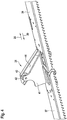
- FIG. 1 shows a perspective view of an embodiment of an advantageous roof sliding window 1, which is particularly suitable for installation in residential roofs.
- a Nachschreibvorraum 2 is shown.
- the Nachschreibvorraumcardi 2 window sash - not shown here - the roof sliding window 1 stacked one above the other and from there side by side slidable in a window opening.
- the Nachschreibvorraumcardi 2 a movable in height frame 3, on which the sash can be stacked.
- FIG. 2 is a schematic side view of the Nachschreibvoruze 2 - seen from the window opening -, depends the frame 3 of the Nachschreibvoruze 2 on both sides of a respective chain hoist 4 and 5.
- the respective chain hoist 4, 5 is on a frame supporting, on a stationary frame 6 of the Nachschreibvoruze 2 guided slide 7 and 8 attached.
- the respective chain hoist 4, 5 leads from the corresponding carriage 7, 8 via a chain wheel 9 or 10 arranged above the frame 3, where the chain hoist is deflected by 180 ° and leads to a further chain wheel 11 or 12 below the frame 3.
- the respective chain hoist 4, 5 is substantially at 90 ° is redirected to a below the frame 3 and in the bottom region of the Nachschreibvortechnik 2 arranged device 13.
- the device 13 has according to FIG. 2 an electric motor rack drive 14, which is operatively connected to the chain hoist 4, and an electric motor rack drive 15, which is operatively connected to the chain hoist 5.
- the rack drives 14 and 15 each have a stationary rack 16 and 17, respectively, on each of which a drive unit 18 or 19 can be moved by an electric motor.
- a holding means 20, 21 is arranged in each case, which may be formed in particular integrally with a housing part of the respective drive unit 18 or 19.
- the holding means 20, 21 are each connected to one end of a spring element 22, 23, whose respective other end is connected to the chain hoist 4 or 5.
- the spring elements 22, 23 are thus interposed between the device 13 and the frame 3. According to the embodiment of the FIG.
- the spring elements 22, 23 each formed as a spiral spring 24 and loaded on train.
- the chain hoists 4, 5 each have two chains running parallel to one another, which are tensioned between an intermediate piece 25 connected to the corresponding end of the respective spring element 22, 23 and the corresponding slide 7, 8.
- the rack drives 14 and 15 of the device 13 not with each other, as in the FIG. 2 for reasons of clarity shown schematically, but are preferably arranged side by side at the same height.
- the drive units 18, 19 are arranged stationary, while the racks 16, 17 corresponding to the holding means 20, 21 and by means of the drive units 18, 19 for adjusting the spring tension can be moved.
- the window sash advantageously have coupling means 31, as they are exemplified in the FIGS. 4 to 6 are shown. On the embodiment and operation of the coupling agent will be discussed in more detail later.
- the frame 3 Due to its weight and / or due to a certain shape of the coupling means 31, the frame 3 is moved downwards, as indicated by an arrow 29, so that the following window sash can be pushed over the window sash 3 lying on the frame. This is repeated until all of the sashes in the follower 2 are stacked one above the other.
- a particular advantage of the roof sliding window is that when moving a sash in the window opening, the device 13 is controlled so that a coupling rearward movement of the remaining window sash is omitted, and from the Nachschreibvorcardi 2 pushed out window sash is moved alone in the window opening without him pulling another window sash after.
- the drive units 18 and 19 on the racks 16 or 17, or alternatively by moving the racks 16, 17 by means of the drive units 18 and 19, the spring tension of the spring elements 22, 23 can be influenced or adjusted in a simple manner. This makes it possible, when moving a sash out of the Nachschreibvoroplasty 2 in the window opening to prevent a coupling nachschreiben.
- the spring tension is reduced while a window sash is moved into the window opening, the spring tension is not sufficient to move the frame 3 with the remaining / remaining window sashes in the direction of arrow 27 upwards. Rather, the window sash remain substantially in the previous position without moving.
- the coupling means 31 can thus not be brought into operation with each other, so that the casement alone or detached from the underlying casement is moved into the window opening or can be.
- the drive 32 is a gear, toothed belt or chain drive, which can be brought into operative connection with the window wings associated racks.
- the drive is in the area close to the window opening, spaced from the frame 3, as in FIG FIG. 3 represented, arranged. This allows the user to move the window sashes individually or continuously in the window opening.
- a clutch is advantageously provided by means of which the drive 32 can be decoupled from the window sashes, so that even in a power failure, for example, the window sash can be moved without the frictional torque of the drive must be overcome.
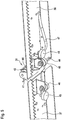
- FIG. 3 is a plan view of the carriage 8, the frame 3 is tiltable about a suitably aligned perpendicular to the direction of movement of the sash axis.
- the FIG. 3 shows on the one hand the frame 3 in a horizontal position in which the frame is parallel or in a plane with the window frame guide 28, so that the lying on the frame 3 sash moved easily and horizontally in or on the frame guide 28 into the window opening can be (for example by means of the electric motor drive 32).
- the shock absorber 33 is correspondingly higher than the shock absorber 34 is formed.
- the shock absorbers 33 and 34 are formed at least partially elastically deformable, so that shocks are damped when tilting the frame 3.
- 7 corresponding shock absorbers are advantageously arranged on the carriage.
- the tilting of the frame 3 allows when moving a sash in or out of the Nachschreibvorraum 2 that the carriage 7, 8 or the frame 3 over the entire travel, so over the entire width of the sash, in height in the direction of arrows 27 or 29, depending on the direction of movement, is moved.
- the frame 3 is advantageously in tilted position (shown in phantom), with its pointing to the frame guide 28 end at the level of the frame guide 28, so that when the first sash is inserted into the Nachschreibvorraum, the frame 3 "slowly" down - in the direction of arrow 29 - is moved.
- the frame 3 can also lie horizontally in the extension of the window frame guide 28 (solid line) when all the window sashes are in the window opening.
- FIGS. 4 to 6 show an embodiment of the above-mentioned coupling means 31 of the window sash of the roof sliding window 1 in different perspective views.
- the FIG. 6 shows for this purpose fittings 35, 36 and 37 of three window wings of the roof sliding window 1.
- the fittings 35, 36 and 37 each have a with the electric motor drive 32 operatively engageable rack 38, 39 and 40 for moving the window sash.
- the fittings 35 to 37 and thus the corresponding associated window sash by means of the coupling means 31 are releasably coupled together.
- the fittings 36 and 37 will now be with reference to the FIGS. 4 and 5 the coupling means 31 will be explained in more detail.
- the fitting 37 has a roller 42 rotatably mounted on a flange 42, whose axis of rotation is aligned perpendicular to the direction of movement of the sash or the fittings 35 to 37.
- the roller 42 in this case forms a driving element 43 of the fitting 37.
- the fitting 36 has at its fitting 37 associated end as entrainment a catch rail 44, which seen in cross section has a U-profile and obliquely, approximately at an angle of 45 ° the fitting 36 is aligned.
- the two legs of the catching rail 44 engage around the roller 42.
- the window sashes are in the window opening, the movement of one of the window sashes or fittings 36, 37 on the other fitting 37, 36 is transmitted via the catching rail 44 and the roller 42.
- the window sash are guided in the window opening, that they are displaceable only in the displacement direction, ie in a plane.
- the frame 3 is tiltably mounted as described above, the lying on the frame 3 sash is tilted accordingly, so that the fitting 36 having window sash over the fitting 37 having window sash can be pushed into the Nachschreibvorraum. Accordingly, it behaves between the fittings 36 and 35. As a result, the casements are stacked one above the other in the Nachschreibvortechnik 2 in a simple manner.
- the catch rail 44 is pushed over the roller 42 when moving a window sash out of the follower 2, so that the driving element 43 of the window sash below (roller 42) not taken.
- the fittings at their ends in each case two mutually perpendicular roller body 45 and 46, which eino in corresponding guides of the window frame guide 28 and thereby support the window sash and lead.
- At least the fitting 36 advantageously has at its catch rail 44 end having a cam contour 47, which is arranged at the bottom spaced from the catch rail 44 such that the roller 42 runs on the cam contour.
- the cam contour 47 causes either the fitting 36 or the fitting 37 and thus the corresponding window sash is tilted so that a bent sheet metal edge of a window sash, which is located on the opposite side of the sash and should prevent the ingress of water between the sashes over the Rolled body 46 is lifted away.
- the advantageous roof sliding window thus provides a simple and inexpensive way to move the sash independently of each other in the window opening, and thus to enable a user in particular to clean the outside of the sash.
Description
Die Erfindung betrifft ein Dachschiebefenster mit mehreren Fensterflügeln, die in einer eine Fensteröffnung freigebenden Offenstellung aus einer die Fensterflügel übereinander stapelnden Nachrückvorrichtung nebeneinander in die Fensteröffnung verschiebbar sind. Derartige Dachschiebefenster werden in der Regel als Wohndachfenster oder beispielsweise auch als Notausstieg oder Rauchwärmeabzug verwendet oder sind derart ausgebildet, und ermöglichenbei einem vergleichsweise geringen Bauraumbedarf das Verschließen beziehungsweise Freigeben einer großen Fensteröffnung. Solche Dachschiebefenster gemäß dem Stand der Technik werden beispielsweise in
Das erfindungsgemäße Dachschiebefenster hat den Vorteil, dass die Fensterflügel unabhängig voneinander in die Fensteröffnung verschoben werden können. Dies erleichtert insbesondere die Reinigung des Dachschiebefensters. Einem Benutzer ist es nämlich nunmehr möglich, beispielsweise einen einzelnen Fensterflügel aus der Nachrückvorrichtung in die Fensteröffnung zu verschieben, sodass er durch die verbleibende freigegebene Fensteröffnung den genannten Fensterflügel insbesondere von außen reinigen kann. Bei einem Dachschiebefenster mit beispielsweise drei Fensterflügeln kann der Benutzer somit beispielsweise zunächst den ersten Fensterflügel in die Fensteröffnung verschieben, diesen von außen reinigen, und anschließend erst den zweiten Fensterflügel, um diesen von außen zu reinigen. Die Außenseite des dritten, in der Nachrückvorrichtung verbliebenen Fensterflügels kann dann in der Nachrückvorrichtung gereinigt werden. Zweckmäßigerweise weist die Nachrückvorrichtung eine entsprechende Zugangsöffnung auf. Gegebenenfalls kann hierzu auch spezielles Reinigungswerkzeug zur Verfügung gestellt werden. Vorteilhafterweise kann der Benutzer entweder bereits bei der Montage oder auch später individuell bestimmen, welche der Fensterflügel miteinander verkuppelt werden sollen, und bei welchen Fensterflügeln ein kuppelndes Nachrücken unterbleiben soll.The roof sliding window according to the invention has the advantage that the window sash can be moved independently of each other in the window opening. This facilitates in particular the cleaning of the roof sliding window. Namely, it is now possible for a user, for example, to move a single window sash out of the follower device into the window opening, so that it can clean the window sash in question, in particular from the outside, through the remaining released window opening. In a roof sliding window with, for example, three window sashes, the user can thus, for example, first move the first window sash into the window opening, clean it from the outside, and then only the second sash in order to clean it from the outside. The outside of the third, remaining in the Nachrückvorrichtung window sash can then be cleaned in the Nachrückvorrichtung. Conveniently, the Nachrückvorrichtung on a corresponding access opening. If necessary, this can be done Also special cleaning tool can be provided. Advantageously, the user can either individually during assembly or even later determine which of the casements to be verkuppelt each other, and in which casement a coupling nachzuschiben should be omitted.
Nach einer vorteilhaften Weiterbildung ist vorgesehen, dass die Nachrückvorrichtung einen in der Höhe verfahrbaren und mit dem Federelement wirkverbundenen Rahmen aufweist, auf dem die Fensterflügel stapelbar sind. Der Nachrückvorgang der Fensterflügel wird somit durch den in der Höhe verfahrbaren Rahmen bewirkt, der mit dem vorgespannten Federelement wirkverbunden ist. Zumindest der zuunterst liegende Fensterflügel sowie der Rahmen weisen vorteilhafterweise entsprechende Führungsmittel zur Führung des Fensterflügels auf dem Rahmen auf.According to an advantageous development it is provided that the Nachrückvorrichtung has a height-movable and operatively connected to the spring element frame on which the sash can be stacked. The Nachrückvorgang the window sash is thus effected by the movable in height frame, which is operatively connected to the prestressed spring element. At least the lowermost window sash and the frame advantageously have corresponding guide means for guiding the window sash on the frame.
Vorteilhafterweise ist das Federelement zwischen dem Rahmen und einem zum Einstellen der Federspannung verlagerbaren Haltemittel der Einrichtung vorgespannt. Das bedeutet, dass die Einrichtung direkt auf das Federelement, insbesondere auf den Federweg des Federelements und damit auf die Federspannung, einwirken kann.Advantageously, the spring element between the frame and a displaceable for adjusting the spring tension holding means of the device is biased. This means that the device can act directly on the spring element, in particular on the spring travel of the spring element and thus on the spring tension.
Bevorzugt ist das Haltemittel elektromotorisch verlagerbar. Dadurch ist eine einfache Ansteuerung beziehungsweise Einstellung der Federspannung möglich. Besonders bevorzugt ist die Einrichtung fernsteuerbar, sodass die Federspannung des Federelements von einem beliebigen Ort einstellbar ist, wodurch die Bedienung und Wartung beziehungsweise Reinigung vereinfacht wird.Preferably, the holding means is displaceable by an electric motor. As a result, a simple control or adjustment of the spring tension is possible. Particularly preferably, the device is remotely controllable, so that the spring tension of the spring element is adjustable from any location, whereby the operation and maintenance or cleaning is simplified.
Mit Vorteil ist vorgesehen, dass die Einrichtung zum Verlagern des Haltemittels einen elektromotorischen Zahnstangenantrieb aufweist. Dabei kann entweder die elektromotorische Antriebseinheit des Zahnstangenantriebs ortsfest angeordnet und die Zahnstange, an der das Haltemittel angeordnet ist, verfahrbar sein. Oder das Haltemittel ist an der Antriebseinheit angeordnet, welche auf der ortsfest angeordneten Zahnstange verfahrbar ist. Zweckmäßigerweise ist die Zahnstange in Längserstreckung des Federelements ausgerichtet, sodass der Federweg beziehungsweise die Federspannung einfach und präzise einstellbar ist.It is advantageously provided that the device for displacing the holding means has an electromotive rack drive. In this case, either the electromotive drive unit of the rack drive can be arranged stationary and the rack on which the holding means is arranged to be movable. Or the holding means is arranged on the drive unit, which is movable on the stationary rack. Conveniently, the rack is aligned in the longitudinal extent of the spring element, so that the spring travel or the spring tension is easy and precise adjustable.
Vorteilhafterweise ist das Federelement als Zugfeder ausgebildet, sodass stets eine Zugkraft von der Einrichtung, beziehungsweise dem Haltemittel, über das Federelement auf den Rahmen übertragen wird. Besonders bevorzugt ist das Federelement als Spiralfeder ausgebildet. Dies erlaubt eine kostengünstige Herstellung des Dachschiebefensters sowie eine einfache Montage. Unabhängig von der Ausbildung des Federelements soll hier angemerkt sein, dass sich die oben beschriebene Einrichtung natürlich nicht nur dazu eignet, bei Bedarf ein kuppelndes Nachrücken zu verhindern, sondern dass sie auch dazu geeignet ist, über die Lebensdauer des Federelements hinweg auftretende Ermüdungserscheinungen sowohl des Federelements als auch anderer das Verfahren des Rahmens der Nachrückvorrichtung betreffender Komponenten zu kompensieren. Ist die Einrichtung fernsteuerbar ausgebildet, wie oben beschrieben, so ermöglicht dies eine einfache Wartung und Nachjustierung des Dachschiebefensters, ohne dass eine Demontage oder Teil-Demontage des Dachschiebefensters erfolgen muss.Advantageously, the spring element is designed as a tension spring, so that a tensile force is always transmitted from the device, or the holding means, via the spring element to the frame. Particularly preferably, the spring element is designed as a spiral spring. This allows a cost-effective production of the roof sliding window and easy installation. Regardless of the design of the spring element should be noted here that the device described above, of course, is not only suitable to prevent a coupling nachrücken if necessary, but that it is also suitable over the life of the spring element away occurring fatigue of both the spring element as well as other components relating to the process of the frame of the follower. If the device is designed to be remotely controllable, as described above, this allows easy maintenance and readjustment of the roof sliding window, without having to dismantle or partially dismantle the roof sliding window.
Nach einer Weiterbildung der Erfindung ist ein Seil-, Zahnriemen- und/oder Kettenzug zwischen dem Rahmen und dem Federelement zwischengeschaltet. Dadurch kann sowohl das Federelement als auch die Einrichtung zum Einstellen der Federspannung bauraumoptimiert in oder an der Nachrückvorrichtung beziehungsweise dem Dachschiebefenster angeordnet werden. Insbesondere ist es hierdurch möglich, die Einrichtung sowie das Federelement in der Nachrückvorrichtung unterhalb des Rahmens und damit der gegebenenfalls auf dem Rahmen gestapelten Fensterflügel anzuordnen. Dies ergibt eine besonders kompakte Anordnung, die dennoch eine effiziente Kraftübertragung für das Nachrücken erlaubt.According to a development of the invention, a cable, Zahnriemen- and / or chain hoist between the frame and the spring element is interposed. This allows both the spring element as Also, the device for adjusting the spring tension space-optimized in or on the Nachrückvorrichtung or the roof sliding window are arranged. In particular, this makes it possible to arrange the device and the spring element in the Nachrückvorrichtung below the frame and thus optionally stacked on the frame window sash. This results in a particularly compact arrangement, yet allows an efficient power transmission for the Nachrücken.
Nach einer vorteilhaften Weiterbildung des Dachschiebefensters ist vorgesehen, dass der in der Höhe verfahrbare Rahmen verkippbar gelagert ist. Bevorzugt ist dabei die Kippachse senkrecht zur Verschieberichtung der Fensterflügel ausgerichtet und vorteilhafterweise in Bezug auf den Rahmen und/oder die Fensterflügel mittig angeordnet. Durch das Verkippen des Rahmens wird insbesondere ermöglicht, dass sowohl beim Nachrücken als auch beim Stapeln die Fensterflügel in Bezug auf die Verschiebeebene in der Fensteröffnung in der Nachrückvorrichtung verkippen können, sodass der Fensterflügel, der aus der Nachrückvorrichtung heraus oder in diese hinein verschoben wird, an dem darunterliegenden schräg gestellten/verkippten Fensterflügel ab- beziehungsweise aufläuft. Hierdurch ergibt sich ein sanftes Nachrücken beziehungsweise Stapeln, bei dem das Verfahren des Rahmens in seiner Höhe über die gesamte Fensterflügelbreite - in Bewegungsrichtung gesehen - erfolgt. Vorteilhafterweise weist die Nachrückvorrichtung mindestens einen, den Rahmen lagernden Schlitten auf, der zweckmäßigerweise an einem ortsfesten Gestell in der Höhe verfahrbar ist.According to an advantageous embodiment of the roof sliding window is provided that the movable in height frame is tiltable. Preferably, the tilting axis is aligned perpendicular to the direction of displacement of the window sash and advantageously arranged centrally with respect to the frame and / or the window sash. The tilting of the frame makes it possible, in particular, for the window sashes to be able to tilt with respect to the displacement plane in the window opening in the follower device, so that the window sash that is moved out of or into the follower device is tilted the underlying inclined / tilted sash off or runs up. This results in a gentle upward or stacking, in which the method of the frame in its height over the entire width of the window - in the direction of movement - takes place. Advantageously, the Nachrückvorrichtung has at least one, the frame overlapping carriage, which is conveniently movable on a stationary frame in height.
Weiterhin ist vorgesehen, dass die Fensterflügel als Kupplungsmittel jeweils mindestens ein Mitnahmeelement aufweisen. Unter einem Mitnahmeelement ist hierbei ein Element zu verstehen, das derart ausgebildet und an einem Fensterflügel angeordnet und/oder ausgerichtet ist, dass es ein entsprechendes Mitnahmeelement eines benachbarten - darüber beziehungsweise darunter liegenden - Fensterflügels beim Verschieben des einen Fensterflügels formschlüssig angreift und dadurch den benachbarten Fensterflügel mitnimmt.Furthermore, it is provided that the window sash as a coupling agent in each case have at least one driving element. Under a Driving element here is an element to understand that is designed and arranged on a window sash and / or aligned that it engages a corresponding entrainment of an adjacent - above or below - window sash when moving a window sash form-fitting and thereby entrains the adjacent sash.
Vorteilhafterweise weisen die oben liegenden Fensterflügel als Mitnahmeelement jeweils eine Fangschiene auf, in die ein Mitnahmeelement eines darunter liegenden Fensterflügels beim kuppelnden Nachrücken eingreift. Beim Verschieben des Fensterflügels aus der Nachrückvorrichtung in die Fensteröffnung, also in den Blendrahmen des Dachschiebefensters, fängt die Fangschiene das Mitnahmeelement des darunter liegenden Fensterflügels - sofern dieser kuppelnd nachrückt -, wodurch die beiden Fensterflügel miteinander gekuppelt werden. Durch entsprechendes Betätigen der oben beschriebenen Einrichtung zum Einstellen der Federspannung wird das kuppelnde Nachrücken unterbunden, sodass die Fangschiene an dem Mitnahmeelement des darunter liegenden Fensterflügels vorbeibewegt wird.Advantageously, the overhead window sash as entrainment each have a catch rail, in which engages a driving element of an underlying sash when coupling rearward. When moving the sash from the Nachrückvorrichtung in the window opening, ie in the frame of Dachschiebefensters, the catching track captures the entrainment of the underlying sash - as long as this moves behind -, whereby the two sash are coupled together. By appropriate actuation of the device described above for adjusting the spring tension, the coupling-up movement is prevented, so that the catch rail is moved past the driving element of the underlying window sash.
Ferner ist vorgesehen, dass das Mitnahmeelement des darunter liegenden Fensterflügels als insbesondere drehbar gelagerte Fangrolle ausgebildet ist. Durch die drehbare Lagerung werden Reibungskräfte zwischen den Fensterflügeln beim Verschieben minimiert und das Verschieben der Fensterflügel insgesamt erleichtert. Zweckmäßigerweise ist die Fangschiene schräg ausgerichtet, wobei insbesondere hier die drehbare Lagerung der Rolle zu einer Reibkraftminderung führt. Durch die Schrägstellung wird außerdem bewirkt, dass beim Verschieben eines Fensterflügels der in der Nachrückvorrichtung darunterliegende Fensterflügel angehoben oder runtergedrückt - je nach Verschiebe-Richtung - und dadurch das Verfahren des Rahmens unterstützt wird.It is further provided that the entrainment element of the underlying window sash is designed as a particular rotatably mounted catch roller. Due to the rotatable mounting frictional forces between the window sashes when moving minimized and the sliding of the sash altogether. Conveniently, the catch rail is aligned obliquely, in particular here the rotatable mounting of the roller leads to a reduction in friction force. The inclination also causes the moving of a window sash raised in the Nachrückvorrichtung underlying sash or pushed down - depending on the direction of the shift - thereby supporting the procedure of the framework.
Vorteilhafterweise weist die Fangschiene im Querschnitt gesehen ein U-Profil auf, wobei die Rolle derart in die Fangschiene eingreift, dass sie mit beiden Schenkeln des U-Profils, je nach Bewegungsrichtung der Fensterflügel, zusammenwirkt. Dadurch wird nicht nur das Mitnehmen des darunter liegenden Fensterflügels gewährleistet, sondern auch der Stapelvorgang in der Nachrückvorrichtung eingeleitet. Werden zwei miteinander gekuppelte Fensterflügel in die Nachrückvorrichtung eingefahren, so wird der in Bewegungsrichtung vorne liegende Fensterflügel bis zu einem vorteilhaft angeordneten Anschlag in die Nachrückvorrichtung beziehungsweise auf den Rahmen der Nachrückvorrichtung verschoben. Sobald der Fensterflügel an den Anschlag trifft, führt die schräg ausgerichtete, das U-Profil aufweisende Fangschiene dazu, dass der auf dem Rahmen der Nachrückvorrichtung liegende Fensterflügel zunächst im Bereich der Rolle, also vorzugsweise an seiner der Fensteröffnung zugewandten Seite, nach unten gedrückt wird, wodurch - falls der Rahmen wie oben beschrieben verkippbar ist - zunächst der Rahmen mitsamt dem darauf liegenden Fensterflügel derart weit verkippt wird, dass der folgende Fensterflügel über den nunmehr darunter verkippten Fensterflügel geschoben und dann der gesamte darunterliegende Fensterflügel beziehungsweise der Rahmen in der Höhe verfahren wird.Advantageously, the catch rail seen in cross-section on a U-profile, wherein the roller engages in the catch rail such that it cooperates with two legs of the U-profile, depending on the direction of movement of the sash. As a result, not only the entrainment of the underlying casement is guaranteed, but also initiated the stacking process in the Nachrückvorrichtung. If two mutually coupled window sash retracted into the Nachrückvorrichtung, so the front lying in the direction of movement window sash is moved to an advantageously arranged stop in the Nachrückvorrichtung or on the frame of the Nachrückvorrichtung. Once the window sash meets the stop, the obliquely oriented, the U-profile having catching rail causes the window sash lying on the frame of the Nachrückvorrichtung is first pressed down in the region of the roller, so preferably on its side facing the window opening, whereby - if the frame is tilted as described above - first the frame is tilted together with the window sash lying on it so far that the following window sash pushed over the now tilted under it sash and then the entire underlying sash or the frame is moved in height.
Nach einer Weiterbildung der Erfindung ist jedem der Fensterflügel eine Zahnstange zugeordnet, die mit einem elektromotorischen Antrieb zum Verschieben der Fensterflügel in der/die Fensteröffnung in Wirkverbindung bringbar ist. Zweckmäßigerweise ist der elektromotorische Antrieb als Untersetzungsantrieb ausgebildet und an der der Fensteröffnung zugeordneten Seite der Nachrückvorrichtung angeordnet. Durch die oben beschriebenen Kupplungsmittel ist es somit auf einfache Art und Weise möglich, mittels des einzigen elektromotorischen Antriebs sämtliche Fensterflügel aus der Nachrückvorrichtung in die Fensteröffnung nebeneinander zu verschieben.According to a development of the invention, each rack is associated with a toothed rack which can be brought into operative connection with an electromotive drive for displacing the casements in the window opening. Conveniently, the electromotive Drive designed as a reduction drive and arranged at the window opening associated side of the Nachrückvorrichtung. By the coupling means described above, it is thus possible in a simple manner, by means of the single electromotive drive to move all the casement from the Nachrückvorrichtung in the window opening next to each other.
Schließlich ist vorgesehen, dass das Dachschiebefenster wenigstens einen Sensor zur Erfassung der Position eines aus der Nachrückvorrichtung zumindest bereichsweise herausgeschobenen Fensterflügels aufweist. Der Sensor ist zweckmäßigerweise mit der Einrichtung zum Einstellen der Federspannung wirkverbunden, sodass der Zeitpunkt, zu dem die Federspannung zum Verhindern eines kuppelnden Nachrückens verringert werden soll, auf einfache Art und Weise mittels des Sensors geregelt/erfasst wird.Finally, it is provided that the roof sliding window has at least one sensor for detecting the position of at least partially pushed out of the Nachrückvorrichtung window sash. The sensor is operatively connected to the means for adjusting the spring tension, so that the time at which the spring tension for preventing a coupling Nachrückens should be reduced, is controlled in a simple manner by the sensor / detected.
Im Folgenden soll die Erfindung anhand eines Ausführungsbeispiels näher erläutert werden. Dazu zeigen
- Figur 1
- eine vorteilhafte Nachrückvorrichtung eines Dachschiebefensters in einer perspektivischen Darstellung,
- Figur 2
- die Nachrückvorrichtung in einer schematischen Seitenansicht,
Figur 3- die Nachrückvorrichtung in einer schematischen Schnittdarstellung,
- Figur 4
- vorteilhafte Kupplungsmittel von Fensterflügeln des Dachschiebefensters in einer perspektivischen Draufsicht,
Figur 5- die Kupplungsmittel in einer perspektivischen Unteransicht und
Figur 6- Beschläge von drei miteinander lösbar gekuppelten Fensterflügeln des Dachschiebefensters in einer perspektivischen Darstellung.
- FIG. 1
- an advantageous Nachrückvorrichtung a Dachschiebefensters in a perspective view,
- FIG. 2
- the Nachrückvorrichtung in a schematic side view,
- FIG. 3
- the Nachrückvorrichtung in a schematic sectional view,
- FIG. 4
- advantageous coupling means of window sashes of the roof sliding window in a perspective plan view,
- FIG. 5
- the coupling means in a perspective bottom view and
- FIG. 6
- Fittings of three detachably coupled window sashes of the roof sliding window in a perspective view.
Die
Wie am besten aus der
Die Einrichtung 13 weist gemäß
Aus der
Im Folgenden soll die Funktionsweise des vorteilhaften Dachschiebefensters näher erläutert werden:
- Bei vollständig freigegebener Fensteröffnung des Dachschiebefensters 1 liegen sämtliche Fensterflügel des Dachschiebefensters übereinander gestapelt in der Nachrückvorrichtung 2 beziehungsweise auf
dem Rahmen 3.Der Rahmen 3 befindet sich dabei auf einer derartigen Höhe, dass der zuoberst liegende Fensterflügel nach rechts beziehungsweise inRichtung eines Pfeils 26 aus der Nachrückvorrichtung 2 herausgeschoben werden kann. Dazu liegt die Unterseite des zuoberst liegenden Fensterflügels im Wesentlichen auf Höhe einer Blendrahmenführung 28 des die Fensteröffnung bildenden Blendrahmens. Durch Verschieben des Fensterflügelsvon dem Rahmen 3 verringert sich das aufden Rahmen 3 wirkende Gesamtgewicht der verbleibenden Fensterflügel, sodass die auf Zug beanspruchten Federelementeden Rahmen 3 mittels der Kettenzüge 4, 5 und derSchlitten Pfeil 27 gekennzeichnet - verfahren. Dadurch rückt der unter dem zuerst verschobenen Fensterflügel liegende Fensterflügel nach. Insbesondere rückt er in die Ausschiebeposition nach, aus der der Fensterflügel dann in die Fensteröffnung verschoben werden kann.
- When fully released window opening of the roof sliding window 1 are all the sash of Dachschiebefensters stacked in the Nachrückvorrichtung 2 or on the
frame 3. Theframe 3 is located at such a height that the uppermost lying window sash to the right or in the direction of anarrow 26 from the Nachrückvorrichtung 2 can be pushed out. For this purpose, the underside of the uppermost window sash lies substantially at the height of a window frame guide 28 of the window opening forming the frame. By moving the sash of theframe 3, the force acting on theframe 3 total weight of the remaining window sash decreases, so that the claimed on train spring elements theframe 3 by means of chain hoists 4, 5 and thecarriage arrow 27 characterized - method. As a result, the window sash below the first window sash moves. In particular, it moves to the Ausschiebeposition from which the window sash can then be moved into the window opening.
Die Fensterflügel weisen dabei vorteilhafterweise Kupplungsmittel 31 auf, wie sie beispielhaft in den
Beim Nachrückvorgang, bei dem aufgrund der vorgespannten Federelemente 22 und 23 der darunter liegende Fensterflügel an den (noch) darüber liegenden Fensterflügel angedrückt wird, werden die Fensterflügel mittels der Kupplungsmittel 31 miteinander gekuppelt, sodass die Bewegung des einen Fensterflügels auf den anderen übertragen wird. Dadurch können sämtliche Fensterflügel aus der Nachrückvorrichtung nach und nach in die Fensteröffnung nebeneinander verschoben werden, wobei hierzu lediglich das Verschieben eines der Fensterflügel notwendig ist. Beim Freigeben der Fensteröffnung funktioniert das oben beschriebene Prinzip genau andersherum. Dabei werden die Fensterflügel in die Nachrückvorrichtung, wie durch einen Pfeil 30 angedeutet, eingeschoben, wobei jeder Fensterflügel nur bis zu einem bestimmten Anschlag auf den Rahmen 3 geschoben werden kann. Aufgrund seiner Gewichtskraft und/oder aufgrund einer bestimmten Form der Kupplungsmittel 31 wird der Rahmen 3 dabei nach unten - wie durch einen Pfeil 29 angedeutet - verfahren, sodass der folgende Fensterflügel über den auf dem Rahmen liegende Fensterflügel 3 geschoben werden kann. Dies wird wiederholt, bis alle Fensterflügel in der Nachrückvorrichtung 2 übereinander gestapelt sind.When Nachrückvorgang in which due to the
Ein besonderer Vorteil des Dachschiebefensters liegt darin, dass beim Verschieben eines Fensterflügels in die Fensteröffnung die Einrichtung 13 derart steuerbar ist, dass ein kuppelndes Nachrücken der verbleibenden Fensterflügel unterbleibt, und der aus der Nachrückvorrichtung 2 herausgeschobene Fensterflügel allein in die Fensteröffnung verschoben wird, ohne dass er einen weiteren Fensterflügel nach sich zieht. Durch Verfahren der Antriebseinheiten 18 und 19 auf den Zahnstangen 16 beziehungsweise 17, oder alternativ durch Verfahren der Zahnstangen 16, 17 mittels der Antriebseinheiten 18 und 19, kann auf einfache Art und Weise die Federspannung der Federelemente 22, 23 beeinflusst beziehungsweise eingestellt werden. Dadurch ist es möglich, beim Verschieben eines Fensterflügels aus der Nachrückvorrichtung 2 in die Fensteröffnung, ein kuppelndes Nachrücken zu verhindern. Wird nämlich die Federspannung verringert, während ein Fensterflügel in die Fensteröffnung verschoben wird, reicht die Federspannung nicht aus, um den Rahmen 3 mit den darauf verbleibenden/verbliebenen Fensterflügeln in Richtung des Pfeils 27 nach oben zu verfahren. Vielmehr verbleiben die Fensterflügel im Wesentlichen in der vorherigen Position ohne nachzurücken. Die Kupplungsmittel 31 können damit nicht in Funktion miteinander gebracht werden, sodass der Fensterflügel alleine beziehungsweise losgelöst von dem darunterliegenden Fensterflügel in die Fensteröffnung verschoben wird beziehungsweise werden kann.A particular advantage of the roof sliding window is that when moving a sash in the window opening, the
Dem Benutzer ermöglicht dies insbesondere ein einfaches und unkompliziertes Reinigen der Außenseite der Fensterflügel. Mittels der Einrichtung 13 ist es ihm möglich, einen oder mehrere Fensterflügel losgelöst von einem oder mehreren anderen der Fensterflügel in die Fensteröffnung zu verschieben, sodass stets ein Bereich der Fensteröffnung freigegeben bleibt. Durch diesen Öffnungsbereich kann der Benutzer hindurchgreifen, um die Außenseite der Fensterflügel zu reinigen. Das beschriebene Dachschiebefenster ermöglicht es somit auf einfache Art und Weise, ohne dass die Kupplungsmittel direkt betätigt werden müssen, ein Miteinander-Kuppeln der Fensterflügel beim Verschieben zu verhindern. Durch die vorteilhafte Ausbildung der Einrichtung 13 ist es möglich, die Fensterflügel in beliebiger Art und Weise verkuppelt oder entkoppelt aus der Nachrückvorrichtung in die Fensteröffnung zu verschieben.This allows the user in particular a simple and straightforward cleaning of the outside of the window sash. By means of the
Da bei derartigen Dachschiebefenstern das Gewicht der einzelnen Fensterflügel vergleichsweise hoch ausfallen kann, ist es von Vorteil, einen elektromotorischen Antrieb 32 zum Verschieben der Fensterflügel vorzusehen. Bevorzugt ist der Antrieb 32 ein Zahnrad-, Zahnriemen- oder Kettenantrieb, der mit den Fensterflügeln zugeordneten Zahnstangen in Wirkverbindung bringbar ist. Zweckmäßigerweise ist der Antrieb im Bereich nahe zu der Fensteröffnung, beabstandet zu dem Rahmen 3, wie in
Wie am besten aus der Schnittdarstellung der
Das Verkippen des Rahmens 3 erlaubt es beim Verschieben eines Fensterflügels in oder aus der Nachrückvorrichtung 2, dass die Schlitten 7, 8 beziehungsweise der Rahmen 3 über den gesamten Verfahrweg, also über die gesamte Breite des Fensterflügels, in der Höhe in Richtung der Pfeile 27 oder 29, je nach Bewegungsrichtung, verfahren wird. Befinden sich sämtliche Fensterflügel nebeneinander in der Fensteröffnung, so liegt der Rahmen 3 vorteilhafterweise in verkippter Position (gestrichelt dargestellt), mit seinem zu der Blendrahmenführung 28 weisenden Ende auf Höhe der Blendrahmenführung 28, sodass wenn der erste Fensterflügel in die Nachrückvorrichtung eingeschoben wird, der Rahmen 3 "langsam" nach unten - in Richtung des Pfeils 29 - verfahren wird. Alternativ kann der Rahmen 3 auch waagerecht in der Verlängerung zu der Blendrahmenführung 28 liegen (durchgezogene Linie), wenn sich alle Fensterflügel in der Fensteröffnung befinden.The tilting of the
Die
Als Kupplungsmittel 31 weist der Beschlag 37 eine an einem Flansch 41 drehbar gelagerte Rolle 42 auf, deren Drehachse senkrecht zur Bewegungsrichtung der Fensterflügel beziehungsweise der Beschläge 35 bis 37 ausgerichtet ist. Die Rolle 42 bildet hierbei ein Mitnahmeelement 43 des Beschlags 37. Der Beschlag 36 weist an seinem dem Beschlag 37 zugeordneten Ende als Mitnahmeelement eine Fangschiene 44 auf, welche im Querschnitt gesehen ein U-Profil aufweist und schräg, etwa in einem Winkel von 45° zu dem Beschlag 36 ausgerichtet ist. Die beiden Schenkel der Fangschiene 44 umgreifen dabei die Rolle 42. Befinden sich die Fensterflügel in der Fensteröffnung, wird somit die Bewegung eines der Fensterflügel beziehungsweise Beschläge 36, 37 auf den anderen Beschlag 37, 36 über die Fangschiene 44 und die Rolle 42 übertragen. Zweckmäßigerweise sind die Fensterflügel derart in der Fensteröffnung geführt, dass diese nur in der Verschieberichtung, also in einer Ebene verlagerbar sind.As a coupling means 31, the fitting 37 has a
Auf der Unterseite des Beschlags 36 endet der dem Beschlag 37 nähergelegene Schenkel der Fangschiene 44 derart unterhalb des ferner gelegenen Schenkels, dass beim Verschieben des Beschlags 36 in die Nachrückvorrichtung 2 die Rolle 42 unterhalb des Beschlags 36 aus der Fangschiene austreten und auf der Unterseite des Beschlags 36 abrollen kann, und dass beim Verschieben des Beschlags 36 aus der Nachrückvorrichtung 2 die Rolle 42 durch den längeren Schenkel der Fangschiene 44 mitgenommen wird. Werden die Fensterflügel in die Nachrückvorrichtung 2 verschoben und liegt der Beschlag 37 beziehungsweise der entsprechende Fensterflügel vollständig auf dem Rahmen 3, so bewirkt die schräggestellte Fangschiene 44 zusammen mit der Rolle 42, dass das die Rolle 42 aufweisende Ende des Beschlags 37 nach unten gedrückt wird. Ist der Rahmen 3 wie oben beschrieben verkippbar gelagert, wird der auf dem Rahmen 3 liegende Fensterflügel entsprechend gekippt, sodass der den Beschlag 36 aufweisende Fensterflügel über den den Beschlag 37 aufweisende Fensterflügel in die Nachrückvorrichtung geschoben werden kann. Entsprechend verhält es sich zwischen den Beschlägen 36 und 35. Hierdurch werden auf einfache Art und Weise die Fensterflügel übereinander in der Nachrückvorrichtung 2 gestapelt.On the underside of the fitting 36 of the fitting 37 closer leg of the
Wird mittels der Einrichtung 13 die Federspannung der Federelement 22 und 23 verändert, sodass ein kuppelndes Nachrücken unterbleibt, wird die Fangschiene 44 beim Verschieben eines Fensterflügels aus der Nachrückvorrichtung 2 über der Rolle 42 vorbeigeschoben, sodass das Mitnahmeelement 43 des darunter liegenden Fensterflügels (Rolle 42) nicht mitgenommen wird.If, by means of the
Zur Führung der Fensterflügel weisen die Beschläge an ihren Enden jeweils zwei senkrecht zueinander stehende Rollenkörper 45 und 46 auf, die in entsprechenden Führungen der Blendrahmenführung 28 einliegen und dadurch die Fensterflügel stützen und führen.To guide the window sash, the fittings at their ends in each case two mutually
Zumindest der Beschlag 36 weist vorteilhafterweise an seinem die Fangschiene 44 aufweisenden Ende eine Nockenkontur 47 auf, die an der Unterseite beabstandet zu der Fangschiene 44 derart angeordnet ist, dass die Rolle 42 über die Nockenkontur abläuft. Die Nockenkontur 47 bewirkt, dass entweder der Beschlag 36 oder der Beschlag 37 und damit der entsprechende Fensterflügel verkippt wird, sodass eine umgebogene Blechkante des einen Fensterflügels, die sich auf der gegenüberliegenden Seite des Fensterflügels befindet und den Wassereintritt zwischen den Fensterflügeln verhindern soll, über den Rollenkörper 46 hinweggehoben wird.At least the fitting 36 advantageously has at its
Insgesamt bietet das vorteilhafte Dachschiebefenster somit eine einfache und kostengünstige Möglichkeit, die Fensterflügel unabhängig voneinander in die Fensteröffnung zu verschieben, und somit einem Benutzer insbesondere das Reinigen der Außenseite der Fensterflügel zu ermöglichen.Overall, the advantageous roof sliding window thus provides a simple and inexpensive way to move the sash independently of each other in the window opening, and thus to enable a user in particular to clean the outside of the sash.
Claims (17)
- A roof sliding window (1) having a plurality of window sashes which, in an open position in which a window opening is uncovered, are slidable from a succession device (2) into the window opening in a side-by-side manner, with the succession device (2) stacking the window sashes one on top of the other, wherein the succession device (2) has at least one biased spring element (22, 23) for an automatic succession of the superposed window sashes, and wherein the window sashes have coupling means (31) which couple a window sash, while it is being slid, to a succession window sash in a detachable manner, characterised in that the succession device (2) has an assembly (13) for adjusting the spring tension of the spring element (22, 23), the assembly (13) being controllable such that a coupling succession is omitted.
- The roof sliding window according to claim 1, characterised in that the succession device (2) has a frame (3) which is movable in height and is operably connected to the spring element (22, 23) and on which the window sashes can be stacked.
- The roof sliding window according to claim 2, characterised in that the spring element (22, 23) is biased between the frame (3) and a holding means (20, 21) of the assembly (13), which holding means (20, 21) can be displaced to adjust the spring tension.
- The roof sliding window according to claim 3, characterised in that the holding means (20, 21) is displaceable in an electromotive manner.
- The roof sliding window according to any one of claims 3 or 4, characterised in that the assembly (13) has an electromotive rack and pinion drive (14, 15) to displace the holding means (20, 21).
- The roof sliding window according to any one of the preceding claims, characterised in that the spring element (22, 23) is formed as an extension spring.
- The roof sliding window according to any one of the preceding claims, characterised in that the spring element (22, 23) is formed as a spiral spring (24).
- The roof sliding window according to any one of claims 2 or 3, characterised in that a cable pull, a toothed belt pull and/or a chain pull (4, 5) is interposed between the frame (3) and the window element (22, 23).
- The roof sliding window according to any one of claims 2, 3 or 8, characterised in that the frame (3) is mounted in a tiltable manner.
- The roof sliding window according to any one of claims 2, 3, 8 or 9, characterised in that the succession device (2) has at least one slide (7, 8) bearing the frame (3).
- The roof sliding window according to any one of the preceding claims, characterised in that the window sashes each have at least one entrainment element (43) as coupling means (31).
- The roof sliding window according to claim 11, characterised in that the window sash lying on top has a guard rail (44) as entrainment element (43), into which the entrainment element (43) of a window sash lying thereunder engages during coupling succession.
- The roof sliding window according to any one of claims 11 or 12, characterised in that the entrainment element (43) of the window sash lying thereunder is formed as a pivot-mounted roller (42).
- The roof sliding window according to claim 12, characterised in that the guard rail (44) has a U-profile as seen in a cross-sectional view.
- The roof sliding window according to any one of claims 12 or 14, characterised in that the guard rail (44) is aligned in an oblique manner as seen in the direction of movement.
- The roof sliding window according to any one of the preceding claims, characterised in that each of the window sashes has a toothed rack (38, 39, 40) which can be brought into operative connection with a drive (32) for displacing the window sashes in/into the window opening, the drive (32) being, in particular, an electromotive drive.
- The roof sliding window according to any one of the preceding claims, characterised by a sensor for detecting the position of a window sash that has been displaced into the window opening.
Applications Claiming Priority (1)
| Application Number | Priority Date | Filing Date | Title |
|---|---|---|---|
| DE102009034205.2A DE102009034205B4 (en) | 2009-07-15 | 2009-07-15 | Roof sliding window with several window sashes |
Publications (3)
| Publication Number | Publication Date |
|---|---|
| EP2281966A2 EP2281966A2 (en) | 2011-02-09 |
| EP2281966A3 EP2281966A3 (en) | 2015-07-15 |
| EP2281966B1 true EP2281966B1 (en) | 2017-10-11 |
Family
ID=42697509
Family Applications (1)
| Application Number | Title | Priority Date | Filing Date |
|---|---|---|---|
| EP10006078.9A Active EP2281966B1 (en) | 2009-07-15 | 2010-06-11 | Sliding sunroof with multiple window leaves |
Country Status (2)
| Country | Link |
|---|---|
| EP (1) | EP2281966B1 (en) |
| DE (1) | DE102009034205B4 (en) |
Families Citing this family (2)
| Publication number | Priority date | Publication date | Assignee | Title |
|---|---|---|---|---|
| CN113862747B (en) * | 2021-09-09 | 2023-09-19 | 广东兴发铝业(河南)有限公司 | Coating device for oxide film on surface of aluminum profile |
| US11920397B1 (en) | 2022-10-28 | 2024-03-05 | Tie Down, Inc. | Hatch lift assist device |
Family Cites Families (5)
| Publication number | Priority date | Publication date | Assignee | Title |
|---|---|---|---|---|
| DE2844022C2 (en) * | 1978-10-09 | 1980-11-27 | O & K Orenstein & Koppel Ag, 1000 Berlin | Sliding plate device for closing an opening |
| GB9011906D0 (en) * | 1990-05-29 | 1990-07-18 | Emanuel Stephen W | Architectural fittings such as windows and doors |
| DE9016628U1 (en) * | 1990-12-07 | 1991-05-02 | Zenker, Karl-Heinz, 7500 Karlsruhe, De | |
| DE19711469C2 (en) * | 1997-03-18 | 2002-04-18 | Zenker Karl Heinz | Roof windows |
| DE10351941A1 (en) * | 2003-11-07 | 2005-06-09 | Karl-Heinz Zenker | System for handling roof mounted window panels has a hoist to stack the panels and raise them to interlock with similar panels to open and close the window aperture |
-
2009
- 2009-07-15 DE DE102009034205.2A patent/DE102009034205B4/en not_active Expired - Fee Related
-
2010
- 2010-06-11 EP EP10006078.9A patent/EP2281966B1/en active Active
Non-Patent Citations (1)
| Title |
|---|
| None * |
Also Published As
| Publication number | Publication date |
|---|---|
| EP2281966A3 (en) | 2015-07-15 |
| EP2281966A2 (en) | 2011-02-09 |
| DE102009034205B4 (en) | 2014-02-13 |
| DE102009034205A1 (en) | 2011-01-27 |
Similar Documents
| Publication | Publication Date | Title |
|---|---|---|
| EP1886853B1 (en) | Window roller blind actuated by the window handle | |
| EP2152988A1 (en) | Folding façade or folding awning arrangement and actuating device for the same | |
| EP1886854A1 (en) | Manual window roller blind with automatic retract | |
| DE202012001762U1 (en) | Chain drive for an actuator for automatic opening and closing of a ventilation device | |
| WO2016096119A1 (en) | Piece of furniture, in particular a cabinet unit | |
| EP2634341A2 (en) | Folding door with two or more inherently rigid folding shutter elements with alternate element edges that do not bend out and element edges that bend out in alternation and operating device for the same | |
| DE102005043019B4 (en) | Vehicle roof with at least two cover elements | |
| DE2507893C3 (en) | Window lifter for vertically subdivided motor vehicle sliding windows | |
| EP1639224A2 (en) | Sectional door | |
| EP2281966B1 (en) | Sliding sunroof with multiple window leaves | |
| DE3710237A1 (en) | Catching device for doors opening upwards | |
| CH671264A5 (en) | ||
| EP3695081B1 (en) | Lower door section having a folding roller bracket | |
| WO2017109165A1 (en) | Sun protection system | |
| CH635164A5 (en) | RAFFSTORE. | |
| CH711522A2 (en) | <TITLE> A device for automatically actuating a leaf of a lifting and sliding door. | |
| DE102005057385B4 (en) | rolling gate | |
| EP1798361B1 (en) | Door | |
| EP2918762A1 (en) | Lifting/sliding door assembly | |
| DE3442224C2 (en) | ||
| EP3868993B1 (en) | Sliding door, especially a cooling room sliding door | |
| DE102015006741B4 (en) | Swing door operator with telescopic linkage | |
| EP0930416B1 (en) | Roller shutter | |
| EP2475833B1 (en) | Device for actuating an overhead door | |
| DE3010223A1 (en) | Folding door or window shutter - has pull for top sliding carrier rod linked to interconnected groove mounted slats |
Legal Events
| Date | Code | Title | Description |
|---|---|---|---|
| PUAI | Public reference made under article 153(3) epc to a published international application that has entered the european phase |
Free format text: ORIGINAL CODE: 0009012 |
|
| AK | Designated contracting states |
Kind code of ref document: A2 Designated state(s): AL AT BE BG CH CY CZ DE DK EE ES FI FR GB GR HR HU IE IS IT LI LT LU LV MC MK MT NL NO PL PT RO SE SI SK SM TR |
|
| AX | Request for extension of the european patent |
Extension state: BA ME RS |
|
| PUAL | Search report despatched |
Free format text: ORIGINAL CODE: 0009013 |
|
| AK | Designated contracting states |
Kind code of ref document: A3 Designated state(s): AL AT BE BG CH CY CZ DE DK EE ES FI FR GB GR HR HU IE IS IT LI LT LU LV MC MK MT NL NO PL PT RO SE SI SK SM TR |
|
| AX | Request for extension of the european patent |
Extension state: BA ME RS |
|
| RIC1 | Information provided on ipc code assigned before grant |
Ipc: E05D 15/24 20060101ALI20150611BHEP Ipc: E05D 15/12 20060101ALI20150611BHEP Ipc: E04D 13/035 20060101AFI20150611BHEP |
|
| 17P | Request for examination filed |
Effective date: 20151218 |
|
| RBV | Designated contracting states (corrected) |
Designated state(s): AL AT BE BG CH CY CZ DE DK EE ES FI FR GB GR HR HU IE IS IT LI LT LU LV MC MK MT NL NO PL PT RO SE SI SK SM TR |
|
| RIC1 | Information provided on ipc code assigned before grant |
Ipc: E04D 13/035 20060101AFI20170329BHEP Ipc: E05D 15/12 20060101ALI20170329BHEP Ipc: E05D 15/24 20060101ALI20170329BHEP |
|
| GRAP | Despatch of communication of intention to grant a patent |
Free format text: ORIGINAL CODE: EPIDOSNIGR1 |
|
| INTG | Intention to grant announced |
Effective date: 20170516 |
|
| GRAS | Grant fee paid |
Free format text: ORIGINAL CODE: EPIDOSNIGR3 |
|
| GRAA | (expected) grant |
Free format text: ORIGINAL CODE: 0009210 |
|
| AK | Designated contracting states |
Kind code of ref document: B1 Designated state(s): AL AT BE BG CH CY CZ DE DK EE ES FI FR GB GR HR HU IE IS IT LI LT LU LV MC MK MT NL NO PL PT RO SE SI SK SM TR |
|
| REG | Reference to a national code |
Ref country code: GB Ref legal event code: FG4D Free format text: NOT ENGLISH |
|
| REG | Reference to a national code |
Ref country code: CH Ref legal event code: EP |
|
| REG | Reference to a national code |
Ref country code: IE Ref legal event code: FG4D Free format text: LANGUAGE OF EP DOCUMENT: GERMAN |
|
| REG | Reference to a national code |
Ref country code: AT Ref legal event code: REF Ref document number: 936175 Country of ref document: AT Kind code of ref document: T Effective date: 20171115 |
|
| REG | Reference to a national code |
Ref country code: DE Ref legal event code: R096 Ref document number: 502010014239 Country of ref document: DE |
|
| REG | Reference to a national code |
Ref country code: NL Ref legal event code: MP Effective date: 20171011 |
|
| REG | Reference to a national code |
Ref country code: LT Ref legal event code: MG4D |
|
| PG25 | Lapsed in a contracting state [announced via postgrant information from national office to epo] |
Ref country code: NL Free format text: LAPSE BECAUSE OF FAILURE TO SUBMIT A TRANSLATION OF THE DESCRIPTION OR TO PAY THE FEE WITHIN THE PRESCRIBED TIME-LIMIT Effective date: 20171011 |
|
| PG25 | Lapsed in a contracting state [announced via postgrant information from national office to epo] |
Ref country code: NO Free format text: LAPSE BECAUSE OF FAILURE TO SUBMIT A TRANSLATION OF THE DESCRIPTION OR TO PAY THE FEE WITHIN THE PRESCRIBED TIME-LIMIT Effective date: 20180111 Ref country code: ES Free format text: LAPSE BECAUSE OF FAILURE TO SUBMIT A TRANSLATION OF THE DESCRIPTION OR TO PAY THE FEE WITHIN THE PRESCRIBED TIME-LIMIT Effective date: 20171011 Ref country code: SE Free format text: LAPSE BECAUSE OF FAILURE TO SUBMIT A TRANSLATION OF THE DESCRIPTION OR TO PAY THE FEE WITHIN THE PRESCRIBED TIME-LIMIT Effective date: 20171011 Ref country code: LT Free format text: LAPSE BECAUSE OF FAILURE TO SUBMIT A TRANSLATION OF THE DESCRIPTION OR TO PAY THE FEE WITHIN THE PRESCRIBED TIME-LIMIT Effective date: 20171011 Ref country code: FI Free format text: LAPSE BECAUSE OF FAILURE TO SUBMIT A TRANSLATION OF THE DESCRIPTION OR TO PAY THE FEE WITHIN THE PRESCRIBED TIME-LIMIT Effective date: 20171011 |
|
| PG25 | Lapsed in a contracting state [announced via postgrant information from national office to epo] |
Ref country code: HR Free format text: LAPSE BECAUSE OF FAILURE TO SUBMIT A TRANSLATION OF THE DESCRIPTION OR TO PAY THE FEE WITHIN THE PRESCRIBED TIME-LIMIT Effective date: 20171011 Ref country code: LV Free format text: LAPSE BECAUSE OF FAILURE TO SUBMIT A TRANSLATION OF THE DESCRIPTION OR TO PAY THE FEE WITHIN THE PRESCRIBED TIME-LIMIT Effective date: 20171011 Ref country code: IS Free format text: LAPSE BECAUSE OF FAILURE TO SUBMIT A TRANSLATION OF THE DESCRIPTION OR TO PAY THE FEE WITHIN THE PRESCRIBED TIME-LIMIT Effective date: 20180211 Ref country code: BG Free format text: LAPSE BECAUSE OF FAILURE TO SUBMIT A TRANSLATION OF THE DESCRIPTION OR TO PAY THE FEE WITHIN THE PRESCRIBED TIME-LIMIT Effective date: 20180111 Ref country code: GR Free format text: LAPSE BECAUSE OF FAILURE TO SUBMIT A TRANSLATION OF THE DESCRIPTION OR TO PAY THE FEE WITHIN THE PRESCRIBED TIME-LIMIT Effective date: 20180112 |
|
| REG | Reference to a national code |
Ref country code: DE Ref legal event code: R097 Ref document number: 502010014239 Country of ref document: DE |
|
| PG25 | Lapsed in a contracting state [announced via postgrant information from national office to epo] |
Ref country code: SK Free format text: LAPSE BECAUSE OF FAILURE TO SUBMIT A TRANSLATION OF THE DESCRIPTION OR TO PAY THE FEE WITHIN THE PRESCRIBED TIME-LIMIT Effective date: 20171011 Ref country code: CZ Free format text: LAPSE BECAUSE OF FAILURE TO SUBMIT A TRANSLATION OF THE DESCRIPTION OR TO PAY THE FEE WITHIN THE PRESCRIBED TIME-LIMIT Effective date: 20171011 Ref country code: DK Free format text: LAPSE BECAUSE OF FAILURE TO SUBMIT A TRANSLATION OF THE DESCRIPTION OR TO PAY THE FEE WITHIN THE PRESCRIBED TIME-LIMIT Effective date: 20171011 Ref country code: EE Free format text: LAPSE BECAUSE OF FAILURE TO SUBMIT A TRANSLATION OF THE DESCRIPTION OR TO PAY THE FEE WITHIN THE PRESCRIBED TIME-LIMIT Effective date: 20171011 |
|
| PLBE | No opposition filed within time limit |
Free format text: ORIGINAL CODE: 0009261 |
|
| STAA | Information on the status of an ep patent application or granted ep patent |
Free format text: STATUS: NO OPPOSITION FILED WITHIN TIME LIMIT |
|
| PG25 | Lapsed in a contracting state [announced via postgrant information from national office to epo] |
Ref country code: IT Free format text: LAPSE BECAUSE OF FAILURE TO SUBMIT A TRANSLATION OF THE DESCRIPTION OR TO PAY THE FEE WITHIN THE PRESCRIBED TIME-LIMIT Effective date: 20171011 Ref country code: SM Free format text: LAPSE BECAUSE OF FAILURE TO SUBMIT A TRANSLATION OF THE DESCRIPTION OR TO PAY THE FEE WITHIN THE PRESCRIBED TIME-LIMIT Effective date: 20171011 Ref country code: PL Free format text: LAPSE BECAUSE OF FAILURE TO SUBMIT A TRANSLATION OF THE DESCRIPTION OR TO PAY THE FEE WITHIN THE PRESCRIBED TIME-LIMIT Effective date: 20171011 Ref country code: RO Free format text: LAPSE BECAUSE OF FAILURE TO SUBMIT A TRANSLATION OF THE DESCRIPTION OR TO PAY THE FEE WITHIN THE PRESCRIBED TIME-LIMIT Effective date: 20171011 |
|
| 26N | No opposition filed |
Effective date: 20180712 |
|
| PG25 | Lapsed in a contracting state [announced via postgrant information from national office to epo] |
Ref country code: MT Free format text: LAPSE BECAUSE OF FAILURE TO SUBMIT A TRANSLATION OF THE DESCRIPTION OR TO PAY THE FEE WITHIN THE PRESCRIBED TIME-LIMIT Effective date: 20171011 |
|
| PG25 | Lapsed in a contracting state [announced via postgrant information from national office to epo] |
Ref country code: SI Free format text: LAPSE BECAUSE OF FAILURE TO SUBMIT A TRANSLATION OF THE DESCRIPTION OR TO PAY THE FEE WITHIN THE PRESCRIBED TIME-LIMIT Effective date: 20171011 |
|
| REG | Reference to a national code |
Ref country code: CH Ref legal event code: PL |
|
| GBPC | Gb: european patent ceased through non-payment of renewal fee |
Effective date: 20180611 |
|
| REG | Reference to a national code |
Ref country code: BE Ref legal event code: MM Effective date: 20180630 |
|
| REG | Reference to a national code |
Ref country code: IE Ref legal event code: MM4A |
|
| PG25 | Lapsed in a contracting state [announced via postgrant information from national office to epo] |
Ref country code: LU Free format text: LAPSE BECAUSE OF NON-PAYMENT OF DUE FEES Effective date: 20180611 Ref country code: MC Free format text: LAPSE BECAUSE OF FAILURE TO SUBMIT A TRANSLATION OF THE DESCRIPTION OR TO PAY THE FEE WITHIN THE PRESCRIBED TIME-LIMIT Effective date: 20171011 |
|
| PG25 | Lapsed in a contracting state [announced via postgrant information from national office to epo] |
Ref country code: CH Free format text: LAPSE BECAUSE OF NON-PAYMENT OF DUE FEES Effective date: 20180630 Ref country code: LI Free format text: LAPSE BECAUSE OF NON-PAYMENT OF DUE FEES Effective date: 20180630 Ref country code: IE Free format text: LAPSE BECAUSE OF NON-PAYMENT OF DUE FEES Effective date: 20180611 Ref country code: FR Free format text: LAPSE BECAUSE OF NON-PAYMENT OF DUE FEES Effective date: 20180630 Ref country code: GB Free format text: LAPSE BECAUSE OF NON-PAYMENT OF DUE FEES Effective date: 20180611 |
|
| PG25 | Lapsed in a contracting state [announced via postgrant information from national office to epo] |
Ref country code: BE Free format text: LAPSE BECAUSE OF NON-PAYMENT OF DUE FEES Effective date: 20180630 |
|
| REG | Reference to a national code |
Ref country code: AT Ref legal event code: MM01 Ref document number: 936175 Country of ref document: AT Kind code of ref document: T Effective date: 20180611 |
|
| PG25 | Lapsed in a contracting state [announced via postgrant information from national office to epo] |
Ref country code: AT Free format text: LAPSE BECAUSE OF NON-PAYMENT OF DUE FEES Effective date: 20180611 |
|
| PG25 | Lapsed in a contracting state [announced via postgrant information from national office to epo] |
Ref country code: TR Free format text: LAPSE BECAUSE OF FAILURE TO SUBMIT A TRANSLATION OF THE DESCRIPTION OR TO PAY THE FEE WITHIN THE PRESCRIBED TIME-LIMIT Effective date: 20171011 |
|
| PG25 | Lapsed in a contracting state [announced via postgrant information from national office to epo] |
Ref country code: PT Free format text: LAPSE BECAUSE OF FAILURE TO SUBMIT A TRANSLATION OF THE DESCRIPTION OR TO PAY THE FEE WITHIN THE PRESCRIBED TIME-LIMIT Effective date: 20171011 Ref country code: HU Free format text: LAPSE BECAUSE OF FAILURE TO SUBMIT A TRANSLATION OF THE DESCRIPTION OR TO PAY THE FEE WITHIN THE PRESCRIBED TIME-LIMIT; INVALID AB INITIO Effective date: 20100611 |
|
| PG25 | Lapsed in a contracting state [announced via postgrant information from national office to epo] |
Ref country code: CY Free format text: LAPSE BECAUSE OF FAILURE TO SUBMIT A TRANSLATION OF THE DESCRIPTION OR TO PAY THE FEE WITHIN THE PRESCRIBED TIME-LIMIT Effective date: 20171011 Ref country code: MK Free format text: LAPSE BECAUSE OF NON-PAYMENT OF DUE FEES Effective date: 20171011 |
|
| PG25 | Lapsed in a contracting state [announced via postgrant information from national office to epo] |
Ref country code: AL Free format text: LAPSE BECAUSE OF FAILURE TO SUBMIT A TRANSLATION OF THE DESCRIPTION OR TO PAY THE FEE WITHIN THE PRESCRIBED TIME-LIMIT Effective date: 20171011 |
|
| PGFP | Annual fee paid to national office [announced via postgrant information from national office to epo] |
Ref country code: DE Payment date: 20230620 Year of fee payment: 14 |