EP3017760A1 - Tube respiratoire destiné à être utilisé dans des systèmes de débitmètre à ultra-sons - Google Patents
Tube respiratoire destiné à être utilisé dans des systèmes de débitmètre à ultra-sons Download PDFInfo
- Publication number
- EP3017760A1 EP3017760A1 EP14198887.3A EP14198887A EP3017760A1 EP 3017760 A1 EP3017760 A1 EP 3017760A1 EP 14198887 A EP14198887 A EP 14198887A EP 3017760 A1 EP3017760 A1 EP 3017760A1
- Authority
- EP
- European Patent Office
- Prior art keywords
- breathing tube
- tube according
- breathing
- indicator
- section
- Prior art date
- Legal status (The legal status is an assumption and is not a legal conclusion. Google has not performed a legal analysis and makes no representation as to the accuracy of the status listed.)
- Granted
Links
- 230000029058 respiratory gaseous exchange Effects 0.000 title claims abstract description 116
- 238000002604 ultrasonography Methods 0.000 title description 8
- 230000000241 respiratory effect Effects 0.000 claims abstract description 9
- 230000003287 optical effect Effects 0.000 claims abstract description 7
- 241001465754 Metazoa Species 0.000 claims abstract description 4
- 238000000034 method Methods 0.000 claims description 7
- 238000007789 sealing Methods 0.000 claims description 6
- 239000000463 material Substances 0.000 claims description 5
- 238000002347 injection Methods 0.000 claims description 2
- 239000007924 injection Substances 0.000 claims description 2
- 230000008569 process Effects 0.000 claims description 2
- 238000005259 measurement Methods 0.000 description 12
- 230000004888 barrier function Effects 0.000 description 3
- 238000012864 cross contamination Methods 0.000 description 3
- 239000007789 gas Substances 0.000 description 3
- 230000005540 biological transmission Effects 0.000 description 2
- 238000001514 detection method Methods 0.000 description 2
- 238000003780 insertion Methods 0.000 description 2
- 230000037431 insertion Effects 0.000 description 2
- 206010002091 Anaesthesia Diseases 0.000 description 1
- 230000006978 adaptation Effects 0.000 description 1
- 230000037005 anaesthesia Effects 0.000 description 1
- 238000010276 construction Methods 0.000 description 1
- 238000001816 cooling Methods 0.000 description 1
- 238000013461 design Methods 0.000 description 1
- 230000000694 effects Effects 0.000 description 1
- 238000011156 evaluation Methods 0.000 description 1
- 230000004907 flux Effects 0.000 description 1
- 238000001746 injection moulding Methods 0.000 description 1
- 238000004519 manufacturing process Methods 0.000 description 1
- 238000000691 measurement method Methods 0.000 description 1
- 238000010339 medical test Methods 0.000 description 1
- 239000000203 mixture Substances 0.000 description 1
- 230000035515 penetration Effects 0.000 description 1
- 230000009325 pulmonary function Effects 0.000 description 1
- 230000005855 radiation Effects 0.000 description 1
- 230000009467 reduction Effects 0.000 description 1
- 230000004044 response Effects 0.000 description 1
- 238000005070 sampling Methods 0.000 description 1
Images


Classifications
-
- A—HUMAN NECESSITIES
- A61—MEDICAL OR VETERINARY SCIENCE; HYGIENE
- A61B—DIAGNOSIS; SURGERY; IDENTIFICATION
- A61B5/00—Measuring for diagnostic purposes; Identification of persons
- A61B5/08—Detecting, measuring or recording devices for evaluating the respiratory organs
- A61B5/087—Measuring breath flow
-
- A—HUMAN NECESSITIES
- A61—MEDICAL OR VETERINARY SCIENCE; HYGIENE
- A61B—DIAGNOSIS; SURGERY; IDENTIFICATION
- A61B5/00—Measuring for diagnostic purposes; Identification of persons
- A61B5/08—Detecting, measuring or recording devices for evaluating the respiratory organs
- A61B5/082—Evaluation by breath analysis, e.g. determination of the chemical composition of exhaled breath
-
- G—PHYSICS
- G01—MEASURING; TESTING
- G01F—MEASURING VOLUME, VOLUME FLOW, MASS FLOW OR LIQUID LEVEL; METERING BY VOLUME
- G01F1/00—Measuring the volume flow or mass flow of fluid or fluent solid material wherein the fluid passes through a meter in a continuous flow
- G01F1/66—Measuring the volume flow or mass flow of fluid or fluent solid material wherein the fluid passes through a meter in a continuous flow by measuring frequency, phase shift or propagation time of electromagnetic or other waves, e.g. using ultrasonic flowmeters
- G01F1/662—Constructional details
-
- A—HUMAN NECESSITIES
- A61—MEDICAL OR VETERINARY SCIENCE; HYGIENE
- A61B—DIAGNOSIS; SURGERY; IDENTIFICATION
- A61B2503/00—Evaluating a particular growth phase or type of persons or animals
- A61B2503/40—Animals
Definitions
- the invention relates to a breathing tube for use in ultrasonic flow measuring systems for determining the volume flow and / or the molecular weight of the respiration of humans and animals.
- the breathing tubes are usually manufactured by injection molding.
- the openings of the sound openings are usually provided with nets which are injected into the material during the production process. These nets have a very small open area, allow a transmission of sound pulses and prevent on the other hand a stall and thus strong turbulence in the breathing tube. Since only one breathing tube is used per patient, these meshes prevent cross-contamination between patients.
- the object of the invention is to further develop a generic breathing tube so that the aforementioned disadvantages are eliminated.
- the breathing tube for use in ultrasonic flow measurement systems for determining the volume flow and / or the molecular mass of the respiration of humans and animals, the breathing tube is therefore at least partially executed with a polygonal cross-section.
- the breathing tube has at least one indicator which can be read out via an external optical means.
- the at least partially provided polygonal cross section of the breathing tube prevents the breathing tube can be twisted inserted into the measuring system.
- the polygonal cross-section for this purpose is designed asymmetrically, in order to prevent incorrect insertion of the breathing tube (for example, by accidental rotation by a certain angle).
- the at least one indicator can automatically detect the presence of the breathing tube in the measuring system. In addition, the correct positioning in the longitudinal axis of the breathing tube can be ensured within the measuring system. By selecting the indicator, information about the type of breathing tube can also be read out.
- the at least one indicator may be formed by areas on the outer surface of the breathing tube, which differ by the color and / or the degree of reflection from the remaining surface of the breathing tube.
- an optical means such as a light barrier or a reflection light barrier can be read.
- the at least one indicator may be formed by the shape of the outer surface of the breathing tube.
- the breathing tube to form the at least one indicator in the region of at least one edge may be formed like a comb.
- the intermediate spaces formed in the comb-like shaped edge surface for example, light beams can pass onto the optical sensors.
- the breathing tube has a nearly rectangular cross section, wherein the outer sides of the breathing tube are slightly bevelled. This can be used to prevent the breathing tube from being accidentally inserted into the measuring system by 180 °.
- the breathing tube has on its surface at least one circumferential sealing lip.
- the at least one sealing lip in cooperation with the measuring device, in which the breathing tube can be inserted, due to the resulting uniform outward force, a secure seal with the inner surface of the measuring device, i. of the ultrasonic flow measuring system cause.
- the openings in the breathing tube which serve to transmit the Utlraschallimpulse, are advantageously closed by a fabric-like network.
- the fabric-like mesh can be sprayed in each case during the injection process to produce the existing of a sprayable plastic breathing tube made of the same material.
- the fabric-like mesh can also consist of a material that is different from the respiratory tube and can be connected to the respiratory tube in a separate working step to cover the opening.
- the breathing tube may have a separately attachable mouthpiece.
- the breathing tube can additionally have a filter, which can preferably also be designed pluggable.
- the breathing tube can also have on the outer surface at least one projection over which the breathing tube can be pushed out of the Utlraschall flow measuring system.
- different types of the breathing tube may also have different internal cross sections in order to be optimized for specific applications with regard to the volume of the breathing tube and the measurement resolution.
- a reliable detection of the type of breathing tube via the at least one indicator additionally advantageously allows an adaptation of the measurement evaluation of the ultrasonic flow measuring system.
- the linearization of the measured flux signal i. the mathematical relationship between the measured transit times and the output velocity of the volume flow to be matched to the respective breathing tube.
- FIG. 2 An embodiment of the breathing tube according to the invention is in FIG. 2 shown in perspective view.
- This breathing tube is used for insertion into an ultrasonic flow meter, not shown here in detail, as it is for example from the EP 0597060 A1 is known.
- This breathing tube is designed for single use in a patient and has mechanical indicators that can be detected by an optical system.
- the breathing tube has an integrated mouthpiece 1.
- a corresponding stop ring 2 with ejection bottle defines the end position when inserted into the measuring system not shown here, and on the other hand allows with the help of the ejector a slight pushing out of the breathing tube after use thereof.
- the breathing tube has two circumferential sealing lips 3 in its front and rear areas, which serve to seal against the ultrasonic measuring system, not shown here.
- the actual body 4 of the breathing tube has an approximately rectangular cross-section, but the side walls are slightly bevelled. This results in a trapezoidal shape with rounded corners.
- the two openings provided on the opposite sides of the breathing tube, which serve to transmit the ultrasound, are each closed with nets. Finally, a barb 6 is sprayed on the breathing tube, which prevents the breathing tube can be unintentionally pushed out of the measuring system.
- FIG. 3 shows the realization variant described above additionally in a side, top and front view.
- the front view illustrates the substantially rectangular cross section of the breathing tube. It can also be seen that the side walls are designed by their bevel so that the breathing tube can not be rotated by 180 ° inserted into the measuring system.
- the breathing tube of the present invention in the exemplary embodiment illustrated here has an almost rectangular cross-section. This shape has a better "penetration" of the cross section through the ultrasonic beam compared to a round or slightly oval cross-sectional shape.
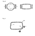
- FIG. 4 Two variants of a breathing tube are shown together with the laterally arranged ultrasonic cells.
- the ultrasonic cells are designated 10 and 20, respectively. Both are both transmitters and receivers of UI-traschallsignalen.
- the area between the two interrupted lines A between the ultrasound cells represents the area of the volume flow covered by the ultrasound beam. This means that in this area the volume flow in the respiratory tube can be measured by the ultrasound beam.
- the total volume flow in the outer region B is not detected by the ultrasound. If the volume flow over the cross section of the breathing tube is distributed unevenly, this effect leads to errors in the measurement result.
- the ratio of the areas A to B is better, ie a larger percentage of the volume flow is actually detected by the ultrasonic measurement signal. This is so in the right embodiment in FIG. 4 , Which substantially corresponds to the shape of the present inventive embodiment, lead to a reduction of the error in uneven distribution of the volume flow in the breathing tube.
- the position of the breathing tube can be detected, since the indicators are arranged along the longitudinal axis. For recognizing the type of respiratory tube, this is coded into the structure of the comb-like indicator. Elevations and depressions in the mechanical structure of the indicator produce characteristic light / shadow sequences on the line sensor. From this image of the indicator on the line sensor, an identification number can be calculated in the control of the ultrasonic flow measuring system.
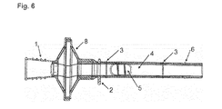
- FIG. 6 shows a longitudinal section through an alternative embodiment of the breathing tube according to the invention.
- this breathing tube corresponds to that according to FIG. 2 , However, here is different from the one in FIG. 2 illustrated embodiment, the mouthpiece 1 and an additional filter insert 8 attachable connected to the rest of the body 4 of the breathing tube.
- the connector provided here allows easy replacement of mouthpiece 1 and / or filter cartridge. 8
Landscapes
- Health & Medical Sciences (AREA)
- Life Sciences & Earth Sciences (AREA)
- Physics & Mathematics (AREA)
- Engineering & Computer Science (AREA)
- Heart & Thoracic Surgery (AREA)
- Physiology (AREA)
- Pulmonology (AREA)
- Veterinary Medicine (AREA)
- Biophysics (AREA)
- Pathology (AREA)
- Public Health (AREA)
- Biomedical Technology (AREA)
- General Health & Medical Sciences (AREA)
- Medical Informatics (AREA)
- Molecular Biology (AREA)
- Surgery (AREA)
- Animal Behavior & Ethology (AREA)
- General Physics & Mathematics (AREA)
- Electromagnetism (AREA)
- Fluid Mechanics (AREA)
- Measurement Of The Respiration, Hearing Ability, Form, And Blood Characteristics Of Living Organisms (AREA)
- Measuring Volume Flow (AREA)
- Infusion, Injection, And Reservoir Apparatuses (AREA)
Priority Applications (1)
| Application Number | Priority Date | Filing Date | Title |
|---|---|---|---|
| PL14198887T PL3017760T3 (pl) | 2014-11-10 | 2014-12-18 | Rurka do oddychania do stosowania w ultradźwiękowych systemach pomiaru przepływu |
Applications Claiming Priority (1)
| Application Number | Priority Date | Filing Date | Title |
|---|---|---|---|
| DE102014016608.2A DE102014016608B3 (de) | 2014-11-10 | 2014-11-10 | Atemrohr zum Einsatz in Ultraschall-Durchflussmesssystemen |
Publications (2)
| Publication Number | Publication Date |
|---|---|
| EP3017760A1 true EP3017760A1 (fr) | 2016-05-11 |
| EP3017760B1 EP3017760B1 (fr) | 2019-06-19 |
Family
ID=52338869
Family Applications (1)
| Application Number | Title | Priority Date | Filing Date |
|---|---|---|---|
| EP14198887.3A Active EP3017760B1 (fr) | 2014-11-10 | 2014-12-18 | Tube respiratoire destiné à être utilisé dans des systèmes de débitmètre à ultra-sons |
Country Status (8)
| Country | Link |
|---|---|
| US (1) | US10786178B2 (fr) |
| EP (1) | EP3017760B1 (fr) |
| JP (1) | JP6029699B2 (fr) |
| CN (1) | CN105581796B (fr) |
| DE (1) | DE102014016608B3 (fr) |
| ES (1) | ES2745463T3 (fr) |
| HU (1) | HUE045767T2 (fr) |
| PL (1) | PL3017760T3 (fr) |
Cited By (3)
| Publication number | Priority date | Publication date | Assignee | Title |
|---|---|---|---|---|
| EP3403578A1 (fr) | 2017-05-16 | 2018-11-21 | ndd Medizintechnik AG | Dispositif de retenue pour un tube respiratoire et procédé pour lire un codage sur une surface d'un tube respiratoire |
| EP3566647A1 (fr) | 2018-05-07 | 2019-11-13 | ndd Medizintechnik AG | Méthode pour vérifier l'étalonnage d'un spiromètre |
| EP4124292A1 (fr) | 2021-07-29 | 2023-02-01 | ndd Medizintechnik AG | Agencement de tube respiratoire pour dispositif de diagnostic de la fonction pulmonaire comprenant un élément de filtration distal |
Families Citing this family (8)
| Publication number | Priority date | Publication date | Assignee | Title |
|---|---|---|---|---|
| HUE050158T2 (hu) | 2017-05-16 | 2020-11-30 | Ndd Medizintechnik Ag | Eljárás légzéscsõ kondicionálására |
| US20180333076A1 (en) | 2017-05-17 | 2018-11-22 | Ndd Medizintechnik Ag | Breathing tube for use in lung function diagnostics |
| USD903095S1 (en) * | 2018-06-19 | 2020-11-24 | SDI Diagnostics Inc. | Breathing tube with in-line filter for lung diagnostics |
| USD918378S1 (en) * | 2018-06-19 | 2021-05-04 | SDI Diagnostics Inc. | Breathing tube with in-line filter for lung diagnostics |
| USD965788S1 (en) * | 2020-07-29 | 2022-10-04 | Ndd Medizintechnik Ag | Tube for a breath analysis device |
| US20230022892A1 (en) * | 2021-07-14 | 2023-01-26 | Sdi Diagnostics, Inc. | Breathing tube for use with spirometers that employ ultrasonic measurement systems |
| CN113558659B (zh) * | 2021-07-30 | 2023-07-04 | 重庆安酷科技有限公司 | 一种高精度超声波肺功能检测仪及其检测方法 |
| US20230191306A1 (en) * | 2021-12-22 | 2023-06-22 | Sdi Diagnostics, Inc. | Breathing tube filter and filter assembly |
Citations (7)
| Publication number | Priority date | Publication date | Assignee | Title |
|---|---|---|---|---|
| DE3941546A1 (de) * | 1989-12-15 | 1991-06-20 | Siemens Ag | Ultraschall-gas-/fluessigkeits-durchflussmesser |
| EP0597060A1 (fr) | 1992-06-03 | 1994-05-18 | Reutter Georg | Spirometre, notamment spirometre a ultra-sons. |
| US5647370A (en) | 1994-07-01 | 1997-07-15 | Ndd Medizintechnik Gmbh | Ultrasonic spirometer |
| DE19605652A1 (de) * | 1996-02-15 | 1997-08-21 | Siemens Ag | Verfahren zur Kalibrierung eines Durchflußmessers |
| US6612306B1 (en) * | 1999-10-13 | 2003-09-02 | Healthetech, Inc. | Respiratory nitric oxide meter |
| JP2008107234A (ja) * | 2006-10-26 | 2008-05-08 | Matsushita Electric Ind Co Ltd | 超音波式流体計測装置 |
| DE102009036288A1 (de) * | 2009-08-06 | 2011-02-10 | Aceos Gmbh | Vorrichtung zur Entnahme einer Gasprobe aus der menschlichen Atmung |
Family Cites Families (20)
| Publication number | Priority date | Publication date | Assignee | Title |
|---|---|---|---|---|
| US5234117A (en) * | 1991-12-10 | 1993-08-10 | Garvin Dawn R | Straw adaptor for baby bottle |
| US5715831A (en) | 1996-06-21 | 1998-02-10 | Desert Moon Development Limited Partnership | Calibrated air tube for spirometer |
| WO1997048338A1 (fr) * | 1996-06-21 | 1997-12-24 | Desert Moon Development Limited Partnership | Element resistif et tube d'air etalonne pour spirometre |
| US5789660A (en) * | 1996-07-15 | 1998-08-04 | Novametrix Medical Systems, Inc. | Multiple function airway adapter |
| US6126610A (en) * | 1997-11-03 | 2000-10-03 | Novametrix Medical Systems, Inc. | Pneumatic connector with encoding |
| WO1999039637A1 (fr) * | 1998-02-05 | 1999-08-12 | Mault James R | Calorimetre metabolique mettant en application une analyse de gaz respiratoire |
| DE19910620C2 (de) | 1999-03-10 | 2001-02-01 | Siemens Ag | Vorrichtung zur Durchführung von Rechenvorgängen |
| TW504568B (en) * | 1999-03-17 | 2002-10-01 | Matsushita Electric Ind Co Ltd | Ultrasonic flowmeter |
| US6427694B1 (en) * | 2000-11-22 | 2002-08-06 | Mpv-Truma Gesellschaft Fur Medizintechnische Produkte Gmbh | Nasal breathing mask |
| US7018363B2 (en) * | 2001-01-18 | 2006-03-28 | Medrad, Inc. | Encoding and sensing of syringe information |
| KR100462455B1 (ko) * | 2002-05-07 | 2004-12-17 | 이규상 | 밸브 기능을 갖는 스트로우 |
| EP1632178A1 (fr) * | 2004-09-03 | 2006-03-08 | ndd Medizintechnik AG | Methode pour le diagnostique non-cooperative des poumons par ultrasons |
| CN101072981A (zh) * | 2004-12-09 | 2007-11-14 | 柯尼卡美能达医疗印刷器材株式会社 | 流量测定装置 |
| US7785514B2 (en) * | 2006-05-18 | 2010-08-31 | Mccarthy Peter T | Snorkels, flexible tubes, mouthpieces and methods |
| EP2032214B1 (fr) * | 2006-06-07 | 2017-12-06 | Theravent, Inc. | Mécanismes nasaux à couches |
| US8109268B2 (en) | 2007-01-08 | 2012-02-07 | Dräger Medical GmbH | Device for detecting a gas volume flow |
| CN101059338B (zh) | 2007-05-16 | 2010-08-25 | 赵跃 | 基于激光图像测量的煤焦炉炭化室位置检测方法 |
| US10918308B2 (en) * | 2007-05-18 | 2021-02-16 | Koninklijke Philips N.V. | Respiratory component measurement system including a sensor for detecting orientation or motion |
| JP2013250254A (ja) * | 2012-06-01 | 2013-12-12 | Chest M I Inc | 超音波式スパイロメータの多重反射防止整流管 |
| KR101425662B1 (ko) * | 2013-03-05 | 2014-08-05 | 주식회사 세라젬메디시스 | 식별정보를 갖는 바이오 센서 |
-
2014
- 2014-11-10 DE DE102014016608.2A patent/DE102014016608B3/de active Active
- 2014-12-18 PL PL14198887T patent/PL3017760T3/pl unknown
- 2014-12-18 EP EP14198887.3A patent/EP3017760B1/fr active Active
- 2014-12-18 HU HUE14198887A patent/HUE045767T2/hu unknown
- 2014-12-18 ES ES14198887T patent/ES2745463T3/es active Active
-
2015
- 2015-03-02 JP JP2015040069A patent/JP6029699B2/ja active Active
- 2015-07-24 US US14/809,029 patent/US10786178B2/en active Active
- 2015-07-27 CN CN201510447957.5A patent/CN105581796B/zh active Active
Patent Citations (9)
| Publication number | Priority date | Publication date | Assignee | Title |
|---|---|---|---|---|
| DE3941546A1 (de) * | 1989-12-15 | 1991-06-20 | Siemens Ag | Ultraschall-gas-/fluessigkeits-durchflussmesser |
| EP0597060A1 (fr) | 1992-06-03 | 1994-05-18 | Reutter Georg | Spirometre, notamment spirometre a ultra-sons. |
| US5419326A (en) | 1992-06-03 | 1995-05-30 | Ndd Medizintechnik Gmbh | Spirometer, more particularly an ultrasonic spirometer |
| EP0597060B1 (fr) | 1992-06-03 | 1997-04-16 | NDD Medizintechnik GmbH | Spirometre, notamment spirometre a ultra-sons |
| US5647370A (en) | 1994-07-01 | 1997-07-15 | Ndd Medizintechnik Gmbh | Ultrasonic spirometer |
| DE19605652A1 (de) * | 1996-02-15 | 1997-08-21 | Siemens Ag | Verfahren zur Kalibrierung eines Durchflußmessers |
| US6612306B1 (en) * | 1999-10-13 | 2003-09-02 | Healthetech, Inc. | Respiratory nitric oxide meter |
| JP2008107234A (ja) * | 2006-10-26 | 2008-05-08 | Matsushita Electric Ind Co Ltd | 超音波式流体計測装置 |
| DE102009036288A1 (de) * | 2009-08-06 | 2011-02-10 | Aceos Gmbh | Vorrichtung zur Entnahme einer Gasprobe aus der menschlichen Atmung |
Cited By (5)
| Publication number | Priority date | Publication date | Assignee | Title |
|---|---|---|---|---|
| EP3403578A1 (fr) | 2017-05-16 | 2018-11-21 | ndd Medizintechnik AG | Dispositif de retenue pour un tube respiratoire et procédé pour lire un codage sur une surface d'un tube respiratoire |
| US11154219B2 (en) | 2017-05-16 | 2021-10-26 | Ndd Medizintechnik Ag | Holding device for a breathing tube and method for reading out a coding on a surface of a breathing tube |
| EP3566647A1 (fr) | 2018-05-07 | 2019-11-13 | ndd Medizintechnik AG | Méthode pour vérifier l'étalonnage d'un spiromètre |
| US11162833B2 (en) | 2018-05-07 | 2021-11-02 | Ndd Medizintechnik Ag | Method for verifying a calibration of a spirometer |
| EP4124292A1 (fr) | 2021-07-29 | 2023-02-01 | ndd Medizintechnik AG | Agencement de tube respiratoire pour dispositif de diagnostic de la fonction pulmonaire comprenant un élément de filtration distal |
Also Published As
| Publication number | Publication date |
|---|---|
| PL3017760T3 (pl) | 2019-12-31 |
| HUE045767T2 (hu) | 2020-01-28 |
| US10786178B2 (en) | 2020-09-29 |
| CN105581796A (zh) | 2016-05-18 |
| JP6029699B2 (ja) | 2016-11-24 |
| EP3017760B1 (fr) | 2019-06-19 |
| US20160128608A1 (en) | 2016-05-12 |
| JP2016087412A (ja) | 2016-05-23 |
| CN105581796B (zh) | 2021-08-17 |
| DE102014016608B3 (de) | 2016-04-07 |
| ES2745463T3 (es) | 2020-03-02 |
Similar Documents
| Publication | Publication Date | Title |
|---|---|---|
| EP3017760B1 (fr) | Tube respiratoire destiné à être utilisé dans des systèmes de débitmètre à ultra-sons | |
| EP3489634B1 (fr) | Dispositif de mesure par ultrasons et procédé de mesure par ultrasons sur un fluide s'écoulant | |
| DE10035054C1 (de) | Atemstromsensor | |
| DE4222286C1 (de) | Ultraschall-Spirometer | |
| EP3404372B1 (fr) | Débitmètre ultrasonique | |
| EP3639023A1 (fr) | Mesure du taux d'alcool dans l'air expiré avec prélèvement d'échantillon sans contact | |
| DE102008002166A1 (de) | Messsystem zur Bestimmung und/oder Überwachung des Durchflusses eines Messmediums durch ein Messrohr | |
| DE10258997A1 (de) | Vorrichtung zur Postionierung eines Clamp-On Durchflußmeßgeräts an einem Behältnis | |
| EP3343185B1 (fr) | Débitmètre à ultrasons et procédé de mesure du débit | |
| DE102017202896B4 (de) | Durchflussmessanordnung sowie Messumformer zur Prozessinstrumentierung mit einer derartigen Durchflussmessanordnung | |
| DE102008063503A1 (de) | Lungendiagnosegerät mit vier Ultraschallelementen | |
| DE102004017403A1 (de) | Messvorrichtung zur Messung von Volumenstrom oder Stoffeigenschaften eines Gases, dessen Strömungsrichtung sich umkehren kann | |
| DE102010053261A1 (de) | Messkapsel zur Durchflussmessung | |
| DE102008060922A1 (de) | Lungendiagnosegerät mit zwei Ultraschallmessstrecken | |
| EP3536359A1 (fr) | Tire-lait | |
| DE102019001995B3 (de) | Behälter zur Aufbewahrung, Mischung und/oder Kultivierung eines Mediums | |
| DE202008013879U1 (de) | Volumenstrommessanordnung sowie Volumenstromregler mit einer Volumenstrommessanordnung | |
| DE20321641U1 (de) | Atemvolumenstromsensor | |
| EP2310811A2 (fr) | Procédé et dispositif de détermination d'un débit de fluide | |
| EP3301410A1 (fr) | Localisation d'un événement au niveau du signal de capteur | |
| DE102009036288B4 (de) | Vorrichtung zur Entnahme einer Gasprobe aus der menschlichen Atmung | |
| DE102008054257B4 (de) | Verfahren zur Bestimmung der Strömungsgeschwindigkeit eines Atemgases | |
| EP3748309A1 (fr) | Débitmètre à ultrasons, utilisation d'un débitmètre à ultrasons dans un organe d'arrêt et organe d'arrêt | |
| EP1731883A1 (fr) | Procédé pour détecter un changement géométrique d'un canal de mesure de débit par ultrasons | |
| WO2023160758A1 (fr) | Dispositif médical |
Legal Events
| Date | Code | Title | Description |
|---|---|---|---|
| PUAI | Public reference made under article 153(3) epc to a published international application that has entered the european phase |
Free format text: ORIGINAL CODE: 0009012 |
|
| AK | Designated contracting states |
Kind code of ref document: A1 Designated state(s): AL AT BE BG CH CY CZ DE DK EE ES FI FR GB GR HR HU IE IS IT LI LT LU LV MC MK MT NL NO PL PT RO RS SE SI SK SM TR |
|
| AX | Request for extension of the european patent |
Extension state: BA ME |
|
| STAA | Information on the status of an ep patent application or granted ep patent |
Free format text: STATUS: REQUEST FOR EXAMINATION WAS MADE |
|
| 17P | Request for examination filed |
Effective date: 20161103 |
|
| STAA | Information on the status of an ep patent application or granted ep patent |
Free format text: STATUS: EXAMINATION IS IN PROGRESS |
|
| 17Q | First examination report despatched |
Effective date: 20180919 |
|
| GRAP | Despatch of communication of intention to grant a patent |
Free format text: ORIGINAL CODE: EPIDOSNIGR1 |
|
| STAA | Information on the status of an ep patent application or granted ep patent |
Free format text: STATUS: GRANT OF PATENT IS INTENDED |
|
| INTG | Intention to grant announced |
Effective date: 20190226 |
|
| GRAS | Grant fee paid |
Free format text: ORIGINAL CODE: EPIDOSNIGR3 |
|
| GRAA | (expected) grant |
Free format text: ORIGINAL CODE: 0009210 |
|
| STAA | Information on the status of an ep patent application or granted ep patent |
Free format text: STATUS: THE PATENT HAS BEEN GRANTED |
|
| AK | Designated contracting states |
Kind code of ref document: B1 Designated state(s): AL AT BE BG CH CY CZ DE DK EE ES FI FR GB GR HR HU IE IS IT LI LT LU LV MC MK MT NL NO PL PT RO RS SE SI SK SM TR |
|
| REG | Reference to a national code |
Ref country code: GB Ref legal event code: FG4D Free format text: NOT ENGLISH |
|
| REG | Reference to a national code |
Ref country code: CH Ref legal event code: EP |
|
| REG | Reference to a national code |
Ref country code: IE Ref legal event code: FG4D Free format text: LANGUAGE OF EP DOCUMENT: GERMAN |
|
| REG | Reference to a national code |
Ref country code: DE Ref legal event code: R096 Ref document number: 502014011988 Country of ref document: DE |
|
| REG | Reference to a national code |
Ref country code: AT Ref legal event code: REF Ref document number: 1144456 Country of ref document: AT Kind code of ref document: T Effective date: 20190715 |
|
| REG | Reference to a national code |
Ref country code: NL Ref legal event code: FP |
|
| REG | Reference to a national code |
Ref country code: SE Ref legal event code: TRGR |
|
| PG25 | Lapsed in a contracting state [announced via postgrant information from national office to epo] |
Ref country code: AL Free format text: LAPSE BECAUSE OF FAILURE TO SUBMIT A TRANSLATION OF THE DESCRIPTION OR TO PAY THE FEE WITHIN THE PRESCRIBED TIME-LIMIT Effective date: 20190619 Ref country code: HR Free format text: LAPSE BECAUSE OF FAILURE TO SUBMIT A TRANSLATION OF THE DESCRIPTION OR TO PAY THE FEE WITHIN THE PRESCRIBED TIME-LIMIT Effective date: 20190619 Ref country code: NO Free format text: LAPSE BECAUSE OF FAILURE TO SUBMIT A TRANSLATION OF THE DESCRIPTION OR TO PAY THE FEE WITHIN THE PRESCRIBED TIME-LIMIT Effective date: 20190919 Ref country code: FI Free format text: LAPSE BECAUSE OF FAILURE TO SUBMIT A TRANSLATION OF THE DESCRIPTION OR TO PAY THE FEE WITHIN THE PRESCRIBED TIME-LIMIT Effective date: 20190619 Ref country code: LT Free format text: LAPSE BECAUSE OF FAILURE TO SUBMIT A TRANSLATION OF THE DESCRIPTION OR TO PAY THE FEE WITHIN THE PRESCRIBED TIME-LIMIT Effective date: 20190619 |
|
| REG | Reference to a national code |
Ref country code: CH Ref legal event code: NV Representative=s name: SCHMAUDER AND PARTNER AG PATENT- UND MARKENANW, CH |
|
| REG | Reference to a national code |
Ref country code: LT Ref legal event code: MG4D |
|
| PG25 | Lapsed in a contracting state [announced via postgrant information from national office to epo] |
Ref country code: RS Free format text: LAPSE BECAUSE OF FAILURE TO SUBMIT A TRANSLATION OF THE DESCRIPTION OR TO PAY THE FEE WITHIN THE PRESCRIBED TIME-LIMIT Effective date: 20190619 Ref country code: LV Free format text: LAPSE BECAUSE OF FAILURE TO SUBMIT A TRANSLATION OF THE DESCRIPTION OR TO PAY THE FEE WITHIN THE PRESCRIBED TIME-LIMIT Effective date: 20190619 Ref country code: GR Free format text: LAPSE BECAUSE OF FAILURE TO SUBMIT A TRANSLATION OF THE DESCRIPTION OR TO PAY THE FEE WITHIN THE PRESCRIBED TIME-LIMIT Effective date: 20190920 Ref country code: BG Free format text: LAPSE BECAUSE OF FAILURE TO SUBMIT A TRANSLATION OF THE DESCRIPTION OR TO PAY THE FEE WITHIN THE PRESCRIBED TIME-LIMIT Effective date: 20190919 |
|
| REG | Reference to a national code |
Ref country code: HU Ref legal event code: AG4A Ref document number: E045767 Country of ref document: HU |
|
| PG25 | Lapsed in a contracting state [announced via postgrant information from national office to epo] |
Ref country code: EE Free format text: LAPSE BECAUSE OF FAILURE TO SUBMIT A TRANSLATION OF THE DESCRIPTION OR TO PAY THE FEE WITHIN THE PRESCRIBED TIME-LIMIT Effective date: 20190619 Ref country code: PT Free format text: LAPSE BECAUSE OF FAILURE TO SUBMIT A TRANSLATION OF THE DESCRIPTION OR TO PAY THE FEE WITHIN THE PRESCRIBED TIME-LIMIT Effective date: 20191021 Ref country code: SK Free format text: LAPSE BECAUSE OF FAILURE TO SUBMIT A TRANSLATION OF THE DESCRIPTION OR TO PAY THE FEE WITHIN THE PRESCRIBED TIME-LIMIT Effective date: 20190619 Ref country code: RO Free format text: LAPSE BECAUSE OF FAILURE TO SUBMIT A TRANSLATION OF THE DESCRIPTION OR TO PAY THE FEE WITHIN THE PRESCRIBED TIME-LIMIT Effective date: 20190619 Ref country code: CZ Free format text: LAPSE BECAUSE OF FAILURE TO SUBMIT A TRANSLATION OF THE DESCRIPTION OR TO PAY THE FEE WITHIN THE PRESCRIBED TIME-LIMIT Effective date: 20190619 |
|
| PG25 | Lapsed in a contracting state [announced via postgrant information from national office to epo] |
Ref country code: SM Free format text: LAPSE BECAUSE OF FAILURE TO SUBMIT A TRANSLATION OF THE DESCRIPTION OR TO PAY THE FEE WITHIN THE PRESCRIBED TIME-LIMIT Effective date: 20190619 Ref country code: IS Free format text: LAPSE BECAUSE OF FAILURE TO SUBMIT A TRANSLATION OF THE DESCRIPTION OR TO PAY THE FEE WITHIN THE PRESCRIBED TIME-LIMIT Effective date: 20191019 |
|
| REG | Reference to a national code |
Ref country code: ES Ref legal event code: FG2A Ref document number: 2745463 Country of ref document: ES Kind code of ref document: T3 Effective date: 20200302 |
|
| PG25 | Lapsed in a contracting state [announced via postgrant information from national office to epo] |
Ref country code: DK Free format text: LAPSE BECAUSE OF FAILURE TO SUBMIT A TRANSLATION OF THE DESCRIPTION OR TO PAY THE FEE WITHIN THE PRESCRIBED TIME-LIMIT Effective date: 20190619 |
|
| PG25 | Lapsed in a contracting state [announced via postgrant information from national office to epo] |
Ref country code: IS Free format text: LAPSE BECAUSE OF FAILURE TO SUBMIT A TRANSLATION OF THE DESCRIPTION OR TO PAY THE FEE WITHIN THE PRESCRIBED TIME-LIMIT Effective date: 20200224 |
|
| REG | Reference to a national code |
Ref country code: DE Ref legal event code: R097 Ref document number: 502014011988 Country of ref document: DE |
|
| PLBE | No opposition filed within time limit |
Free format text: ORIGINAL CODE: 0009261 |
|
| STAA | Information on the status of an ep patent application or granted ep patent |
Free format text: STATUS: NO OPPOSITION FILED WITHIN TIME LIMIT |
|
| PG2D | Information on lapse in contracting state deleted |
Ref country code: IS |
|
| 26N | No opposition filed |
Effective date: 20200603 |
|
| PG25 | Lapsed in a contracting state [announced via postgrant information from national office to epo] |
Ref country code: SI Free format text: LAPSE BECAUSE OF FAILURE TO SUBMIT A TRANSLATION OF THE DESCRIPTION OR TO PAY THE FEE WITHIN THE PRESCRIBED TIME-LIMIT Effective date: 20190619 Ref country code: MC Free format text: LAPSE BECAUSE OF FAILURE TO SUBMIT A TRANSLATION OF THE DESCRIPTION OR TO PAY THE FEE WITHIN THE PRESCRIBED TIME-LIMIT Effective date: 20190619 |
|
| PG25 | Lapsed in a contracting state [announced via postgrant information from national office to epo] |
Ref country code: LU Free format text: LAPSE BECAUSE OF NON-PAYMENT OF DUE FEES Effective date: 20191218 Ref country code: IE Free format text: LAPSE BECAUSE OF NON-PAYMENT OF DUE FEES Effective date: 20191218 |
|
| REG | Reference to a national code |
Ref country code: AT Ref legal event code: MM01 Ref document number: 1144456 Country of ref document: AT Kind code of ref document: T Effective date: 20191218 |
|
| PG25 | Lapsed in a contracting state [announced via postgrant information from national office to epo] |
Ref country code: CY Free format text: LAPSE BECAUSE OF FAILURE TO SUBMIT A TRANSLATION OF THE DESCRIPTION OR TO PAY THE FEE WITHIN THE PRESCRIBED TIME-LIMIT Effective date: 20190619 Ref country code: AT Free format text: LAPSE BECAUSE OF NON-PAYMENT OF DUE FEES Effective date: 20191218 |
|
| PG25 | Lapsed in a contracting state [announced via postgrant information from national office to epo] |
Ref country code: MT Free format text: LAPSE BECAUSE OF FAILURE TO SUBMIT A TRANSLATION OF THE DESCRIPTION OR TO PAY THE FEE WITHIN THE PRESCRIBED TIME-LIMIT Effective date: 20190619 |
|
| PG25 | Lapsed in a contracting state [announced via postgrant information from national office to epo] |
Ref country code: MK Free format text: LAPSE BECAUSE OF FAILURE TO SUBMIT A TRANSLATION OF THE DESCRIPTION OR TO PAY THE FEE WITHIN THE PRESCRIBED TIME-LIMIT Effective date: 20190619 |
|
| PGFP | Annual fee paid to national office [announced via postgrant information from national office to epo] |
Ref country code: GB Payment date: 20231220 Year of fee payment: 10 |
|
| PGFP | Annual fee paid to national office [announced via postgrant information from national office to epo] |
Ref country code: TR Payment date: 20231211 Year of fee payment: 10 Ref country code: SE Payment date: 20231219 Year of fee payment: 10 Ref country code: NL Payment date: 20231219 Year of fee payment: 10 Ref country code: HU Payment date: 20231211 Year of fee payment: 10 Ref country code: FR Payment date: 20231219 Year of fee payment: 10 Ref country code: DE Payment date: 20231127 Year of fee payment: 10 |
|
| PGFP | Annual fee paid to national office [announced via postgrant information from national office to epo] |
Ref country code: PL Payment date: 20231102 Year of fee payment: 10 Ref country code: BE Payment date: 20231218 Year of fee payment: 10 |
|
| PGFP | Annual fee paid to national office [announced via postgrant information from national office to epo] |
Ref country code: ES Payment date: 20240118 Year of fee payment: 10 |
|
| PGFP | Annual fee paid to national office [announced via postgrant information from national office to epo] |
Ref country code: CH Payment date: 20240109 Year of fee payment: 10 |
|
| PGFP | Annual fee paid to national office [announced via postgrant information from national office to epo] |
Ref country code: IT Payment date: 20231229 Year of fee payment: 10 |