EP3017425B1 - Synchronization of imaging - Google Patents
Synchronization of imaging Download PDFInfo
- Publication number
- EP3017425B1 EP3017425B1 EP14819582.9A EP14819582A EP3017425B1 EP 3017425 B1 EP3017425 B1 EP 3017425B1 EP 14819582 A EP14819582 A EP 14819582A EP 3017425 B1 EP3017425 B1 EP 3017425B1
- Authority
- EP
- European Patent Office
- Prior art keywords
- image
- image frame
- processing device
- data processing
- area
- Prior art date
- Legal status (The legal status is an assumption and is not a legal conclusion. Google has not performed a legal analysis and makes no representation as to the accuracy of the status listed.)
- Active
Links
- 238000003384 imaging method Methods 0.000 title description 3
- 238000012545 processing Methods 0.000 claims description 110
- 238000004458 analytical method Methods 0.000 claims description 51
- 238000000034 method Methods 0.000 claims description 26
- 238000004590 computer program Methods 0.000 claims description 16
- 238000012544 monitoring process Methods 0.000 claims 1
- 230000015654 memory Effects 0.000 description 14
- 238000012546 transfer Methods 0.000 description 12
- 238000007689 inspection Methods 0.000 description 9
- 239000011159 matrix material Substances 0.000 description 5
- 230000001419 dependent effect Effects 0.000 description 3
- 239000000463 material Substances 0.000 description 3
- 230000005540 biological transmission Effects 0.000 description 2
- 238000004891 communication Methods 0.000 description 2
- 238000001514 detection method Methods 0.000 description 2
- 238000010586 diagram Methods 0.000 description 2
- 238000004519 manufacturing process Methods 0.000 description 2
- 239000000047 product Substances 0.000 description 2
- 230000001960 triggered effect Effects 0.000 description 2
- 239000011111 cardboard Substances 0.000 description 1
- 230000007547 defect Effects 0.000 description 1
- 239000012467 final product Substances 0.000 description 1
- 239000012530 fluid Substances 0.000 description 1
- 230000010365 information processing Effects 0.000 description 1
- 239000007788 liquid Substances 0.000 description 1
- 239000000123 paper Substances 0.000 description 1
- 239000011087 paperboard Substances 0.000 description 1
- 238000011160 research Methods 0.000 description 1
Images

Classifications
-
- D—TEXTILES; PAPER
- D21—PAPER-MAKING; PRODUCTION OF CELLULOSE
- D21G—CALENDERS; ACCESSORIES FOR PAPER-MAKING MACHINES
- D21G9/00—Other accessories for paper-making machines
- D21G9/0009—Paper-making control systems
-
- H—ELECTRICITY
- H04—ELECTRIC COMMUNICATION TECHNIQUE
- H04N—PICTORIAL COMMUNICATION, e.g. TELEVISION
- H04N7/00—Television systems
- H04N7/18—Closed-circuit television [CCTV] systems, i.e. systems in which the video signal is not broadcast
- H04N7/183—Closed-circuit television [CCTV] systems, i.e. systems in which the video signal is not broadcast for receiving images from a single remote source
-
- G—PHYSICS
- G06—COMPUTING; CALCULATING OR COUNTING
- G06T—IMAGE DATA PROCESSING OR GENERATION, IN GENERAL
- G06T7/00—Image analysis
- G06T7/0002—Inspection of images, e.g. flaw detection
- G06T7/0004—Industrial image inspection
-
- G—PHYSICS
- G01—MEASURING; TESTING
- G01N—INVESTIGATING OR ANALYSING MATERIALS BY DETERMINING THEIR CHEMICAL OR PHYSICAL PROPERTIES
- G01N21/00—Investigating or analysing materials by the use of optical means, i.e. using sub-millimetre waves, infrared, visible or ultraviolet light
- G01N21/84—Systems specially adapted for particular applications
- G01N21/88—Investigating the presence of flaws or contamination
- G01N21/8851—Scan or image signal processing specially adapted therefor, e.g. for scan signal adjustment, for detecting different kinds of defects, for compensating for structures, markings, edges
-
- G—PHYSICS
- G01—MEASURING; TESTING
- G01N—INVESTIGATING OR ANALYSING MATERIALS BY DETERMINING THEIR CHEMICAL OR PHYSICAL PROPERTIES
- G01N21/00—Investigating or analysing materials by the use of optical means, i.e. using sub-millimetre waves, infrared, visible or ultraviolet light
- G01N21/84—Systems specially adapted for particular applications
- G01N21/88—Investigating the presence of flaws or contamination
- G01N21/89—Investigating the presence of flaws or contamination in moving material, e.g. running paper or textiles
- G01N21/8901—Optical details; Scanning details
-
- G—PHYSICS
- G01—MEASURING; TESTING
- G01N—INVESTIGATING OR ANALYSING MATERIALS BY DETERMINING THEIR CHEMICAL OR PHYSICAL PROPERTIES
- G01N33/00—Investigating or analysing materials by specific methods not covered by groups G01N1/00 - G01N31/00
- G01N33/34—Paper
- G01N33/346—Paper sheets
-
- G—PHYSICS
- G06—COMPUTING; CALCULATING OR COUNTING
- G06T—IMAGE DATA PROCESSING OR GENERATION, IN GENERAL
- G06T7/00—Image analysis
- G06T7/0002—Inspection of images, e.g. flaw detection
- G06T7/0004—Industrial image inspection
- G06T7/001—Industrial image inspection using an image reference approach
-
- G—PHYSICS
- G06—COMPUTING; CALCULATING OR COUNTING
- G06T—IMAGE DATA PROCESSING OR GENERATION, IN GENERAL
- G06T7/00—Image analysis
- G06T7/40—Analysis of texture
-
- H—ELECTRICITY
- H04—ELECTRIC COMMUNICATION TECHNIQUE
- H04N—PICTORIAL COMMUNICATION, e.g. TELEVISION
- H04N1/00—Scanning, transmission or reproduction of documents or the like, e.g. facsimile transmission; Details thereof
- H04N1/00002—Diagnosis, testing or measuring; Detecting, analysing or monitoring not otherwise provided for
- H04N1/00005—Diagnosis, testing or measuring; Detecting, analysing or monitoring not otherwise provided for relating to image data
-
- H—ELECTRICITY
- H04—ELECTRIC COMMUNICATION TECHNIQUE
- H04N—PICTORIAL COMMUNICATION, e.g. TELEVISION
- H04N1/00—Scanning, transmission or reproduction of documents or the like, e.g. facsimile transmission; Details thereof
- H04N1/00127—Connection or combination of a still picture apparatus with another apparatus, e.g. for storage, processing or transmission of still picture signals or of information associated with a still picture
- H04N1/00249—Connection or combination of a still picture apparatus with another apparatus, e.g. for storage, processing or transmission of still picture signals or of information associated with a still picture with a photographic apparatus, e.g. a photographic printer or a projector
- H04N1/00251—Connection or combination of a still picture apparatus with another apparatus, e.g. for storage, processing or transmission of still picture signals or of information associated with a still picture with a photographic apparatus, e.g. a photographic printer or a projector with an apparatus for taking photographic images, e.g. a camera
-
- H—ELECTRICITY
- H04—ELECTRIC COMMUNICATION TECHNIQUE
- H04N—PICTORIAL COMMUNICATION, e.g. TELEVISION
- H04N23/00—Cameras or camera modules comprising electronic image sensors; Control thereof
- H04N23/70—Circuitry for compensating brightness variation in the scene
- H04N23/73—Circuitry for compensating brightness variation in the scene by influencing the exposure time
-
- G—PHYSICS
- G01—MEASURING; TESTING
- G01N—INVESTIGATING OR ANALYSING MATERIALS BY DETERMINING THEIR CHEMICAL OR PHYSICAL PROPERTIES
- G01N21/00—Investigating or analysing materials by the use of optical means, i.e. using sub-millimetre waves, infrared, visible or ultraviolet light
- G01N21/84—Systems specially adapted for particular applications
- G01N21/88—Investigating the presence of flaws or contamination
- G01N21/8851—Scan or image signal processing specially adapted therefor, e.g. for scan signal adjustment, for detecting different kinds of defects, for compensating for structures, markings, edges
- G01N2021/8887—Scan or image signal processing specially adapted therefor, e.g. for scan signal adjustment, for detecting different kinds of defects, for compensating for structures, markings, edges based on image processing techniques
- G01N2021/889—Scan or image signal processing specially adapted therefor, e.g. for scan signal adjustment, for detecting different kinds of defects, for compensating for structures, markings, edges based on image processing techniques providing a bare video image, i.e. without visual measurement aids
-
- G—PHYSICS
- G06—COMPUTING; CALCULATING OR COUNTING
- G06T—IMAGE DATA PROCESSING OR GENERATION, IN GENERAL
- G06T2207/00—Indexing scheme for image analysis or image enhancement
- G06T2207/30—Subject of image; Context of image processing
- G06T2207/30108—Industrial image inspection
- G06T2207/30124—Fabrics; Textile; Paper
Definitions
- the present invention relates to a method for imaging of continuous manufacturing processes, in which method an area-scan camera is used for imaging of an object to be monitored.
- the invention also relates to a system and a computer program product causing an apparatus to carry out the method.
- the monitored process may contain events that need to be captured completely within a single image.
- the capturing of these events is often triggered by an external trigger signal received, for example, from a photoelectric cell, automatic logic, or a pulse sensor.
- US 2008/0001104 discloses a method of detecting unwanted objects or faults in containers containing a fluid or liquid, wherein at least partly transparent or translucent containers are imaged by a first camera. These containers are also imaged by a second camera in order to confirm the result of said first processing.
- the present invention relates to a method for a computing device, for example, an image data processing device of a machine vision system.
- An area image sensor of the machine vision system exposes an image frame of an object to be monitored without external triggering.
- a part of the image frame may be transferred to the image data processing device for analysing.
- the image data processing device detects a predefined event in that part of the image frame, the configuration of the machine vision system is changed so that a bigger part of at least one further image frame is transferred from the area image sensor to a memory of the image data processing device for further analysis.
- Various aspects of the invention include a method for a computing device of a machine vision system, a machine vision system and a computer program product comprising instructions to perform the method.
- a method for exposing an image frame of an object to be monitored by an area image sensor transmitting an image part of said image frame to an image data processing device, and analysing the image part by said image data processing device, and if said received part of said image frame is detected to comprise at least one predefined event, said image data processing device is arranged to transmit a trigger signal for triggering said area image sensor so that said area image sensor is reconfigured to expose a further image frame and to transmit an image part of said further image frame to said image data processing device for further analysis, wherein the image part of said further image frame is bigger than the image part of said image frame, otherwise if said image part is not detected to comprise a predefined event, said area image sensor continues to expose an image frame of the object to be monitored and to transmit an image part to the image data processing device.
- said image part comprises multiple separate sections of said image frame.
- said image part comprises multiple separate sections of said image frame.
- said image part of said further image frame comprise multiple separate sections or is the whole further image frame.
- said image part comprising at least one predefined event determines the size and position of said image part of said further image, or a number of further image frames.
- said area image sensor is exposing image frames and transmitting image parts without an external trigger signal.
- a machine vision system for an object to be monitored comprising an area image sensor and an image data processing device, wherein said area image sensor is arranged to expose an image frame of said object to be monitored and to transmit an image part of the image frame to said image data processing device for analysing; and wherein said image data processing device is arranged to transmit a trigger signal for triggering said area image sensor so that said area image sensor is reconfigured to expose a further image frame and to transmit an image part of said further image frame to said image data processing device for further analysis, which image part of said further image frame is bigger than the image area part of said image frame, if the received part of said image frame is detected to comprise at least one predefined event, otherwise said area image sensor continues back to expose an image frame of the object to be monitored and to transmit an image part of said image frame to the image data processing device.
- said area image sensor and an image data processing device are part of a smart camera.
- said image part of said image frame comprises multiple separate sections.
- said image part of the further image frame comprises multiple separate sections of said image frame or is the whole further image frame.
- said image part of the image frame comprising at least one predefined event determines the size and position of said further image frame, or the number of further image frames.
- said area image sensor is arranged to expose an image frame of the object to be monitored and to transmit an image part of said image frame to said image data processing device after said image part of said further image frame is transmitted to said image data processing device for further analysis.
- said area image sensor is configured to expose image frames and transmit parts of image frames without an external trigger signal.
- a computer program product stored on a computer readable medium and executable in a computing device, wherein the computer program product comprises instructions to expose an image frame of an object to be monitored by an area image sensor, transmit an image part of said image frame to an image data processing device, analyse the image part by said image data processing device, and further if said image part of said image frame is detected to comprise at least one predefined event, said image data processing device is instructed to transmit a trigger signal for triggering said area image sensor so that said area image sensor is reconfigured to expose a further image frame and transmit an image bigger part of said further image frame to said image data processing device for further analysis, which image part of said further image frame is bigger than the image part of said image frame, or if said image part of said image frame is not detected to comprise a predefined event, said area image sensor is instructed to continue expose at least one further image frame of the object to be monitored and to transmit an image part of said image frame to the image data processing device.
- said image part of the image frame comprises multiple separate sections of said image frame.
- said image part of the further image frame comprises multiple separate sections of said image frame or is the whole image frame.
- said image part of said image frame comprising at least one predefined event determines the size and position of said further image frame, or a number of further image frames.
- the computer program product further comprises instructions to expose an image frame of the object to be monitored and to transmit an image part of said image frame to said image data processing device after said image part of said further image frame is transmitted to said image data processing device for further analysis.
- said area image sensor is instructed to expose image frames and transmit image parts of said image frames without an external trigger signal.
- an area image sensor of a machine vision system inspects a moving object and exposes images one image frame, i.e. image matrix at a time as the object being monitored moves past the field of view of the area image sensor. Exposed images are captured images.
- the object to be monitored may be, for example, the web-like material of a paper or cardboard machine, or some other kind of machine comprising moving parts to be monitored, such as a printing machine comprising a moving roll, or an assembly machine.
- Each exposed image is transferred to a processing unit for analysis.
- the image transferring process from the sensor to the processing unit is time consuming, and thus the larger the size of the images being transferred, the lower the frame frequency of the camera system must be.
- events that need to be captured completely within a single image may instead end up being captured only partly, for example so that part of the event is in one image and the rest is in the following image. Therefore, machine vision systems are often externally triggered by an external trigger signal received, for example, from a photoelectric cell, automatic logic or pulse sensor, for giving an indication of when images should be exposed so that the whole event is captured within a single image.
- image matrix sensors in machine vision systems for the aforementioned usage without external triggering if only a part of the image frame i.e. image matrix is read and transferred to an image data processing device such as to a logic circuit, digital signal processor (DSP) or an image data computer.
- DSP digital signal processor
- This read and transferred part of the image frame may be called, for example, a synchronizing image area.
- the configuration of the image sensor is changed so that the whole image frame, or at least a bigger part of the image frame than the synchronizing image area, is read and transferred from the camera to a memory of the image data processing device for further analysis and/or measuring.
- the predefined event may be, for example, a hole that is made on purpose to the moving object and/or a deviation such as a definite change, pattern and/or unwanted hole in the object or any other event that is suitable to be monitored by used camera.
- the predefined event is defined for the image data processing device in advance.
- the detected event acts as a trigger for the machine vision system that causes the transmission of the whole, or at least a bigger part of at least one image frame to the image data processing device and for further analysis of the image in the image data processing device.
- the size and position of the bigger part of the image frame are dependent on conditions in the synchronizing image area, for example so that the bigger part is aligned to contain the detected event in the middle of the transmitted image area.
- the image sensor is not configured to transfer a bigger part of the first image frame after the detected event, but is instead configured to transfer a bigger part of the image frame after, for example, a predetermined number of image frames from the detected event. After transmitting the bigger part of at least one frame, the machine vision system is reconfigured and it resumes reading and transferring only synchronizing image areas until a new predefined event is detected.
- an area image sensor captures images i.e. image frames of a moving object. For capturing an image of the object the image frame area is exposed and exposed image frame area is then captured. In fact capturing includes exposing. After capturing of the image frame area, the area image sensor transmits a part of that image frame to an image data processing device. This transmitted part is so called synchronizing image area part.
- the image data processing device analyses the synchronizing image area part for detecting a predefined event(s). If the image data processing device detect a predefined event(s) it is arranged to transmit a trigger signal for triggering the area image sensor. On the basis of this trigger signal the area image sensor is reconfigured i.e. configuration of the area image sensor is changed. The area image sensor captures a new image frame essentially from the same area of the object as the image frame comprising the synchronizing image area part comprising the detected predefined event(s).
- the area image sensor reads a part of the new image frame.
- This part may be called as a further analysis area part.
- the area image sensor reads more than one parts of the new image frame.
- the further analysis area part is bigger than the synchronizing image area part, for example, so that whole predefined event can be seen from the new part if the predefined event was only partly shown in synchronizing image area part.
- the further analysis area part is smaller or the same size than the synchronizing image area part.
- the further analysis area part may also have different shape. After reading the further analysis area part, the area image sensor transmits this further analysis area part to the image data processing device for further analysis.
- the area image sensor is again reconfigured and it returns to image and transmit synchronizing image area part(s). However, if the area image sensor does not found any predefined event(s), the area image sensor continues to image and transmit synchronizing image area part(s) to the image data processing device that analyses those parts to find predefined event(s).
- a synchronizing image part of the image frame and a further analysis area part of the image frame may comprise multiple separate sections of said image frame i.e. it may consist of several parts.
- the further analysis area part may also be the whole image frame.
- the further analysis area part's size and position relative to the image frame may be determined on the basis of the synchronizing image part comprising at least one predefined event.
- the synchronizing image part comprising at least one predefined event may also determine a number of image frames that are taken for further analysis.
- the area image sensor may capture and transmit synchronizing image parts without an external trigger signal, because the size of the synchronizing image part is predetermined small enough.
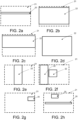
- Figures 1a, 1b and 1c show inspection states of a machine vision system according to an example.
- An area image sensor 10 is arranged to expose images from an object to be monitored 11.
- the object to be monitored 11 is movable web-like material.
- Figure 1a shows a first state, a so-called normal state of the machine vision system, where the area image sensor 10 exposes and transfers a synchronizing image area to a memory of an image data processing device (not shown).
- This synchronizing image area 12 is a part of the image frame 13 i.e. image matrix 13 exposed by the sensor 10 from the object to be monitored 11.
- the image data processing device is configured to detect events 14 from the synchronizing image area 12. Events 14 to be detected are defined for the processing device in advance.
- the event 14 to be detected is a deviation on the moving object to be monitored 11, for example, a hole. If the image data processing device detects at least one event 14 in the synchronizing image area 12, the machine vision system changes to a second state shown in figure 1b , where the sensor 10 is re-configured by the image data processing device so that the sensor 10 of the machine vision system reads and transfers a bigger part 15 of at least one image frame 13 to the memory of the image data processing device for more detailed analysis.
- the bigger part 15 of the image frame 13 is so-called further analysis area. In this example, the bigger part 15 is same as the image frame 13.
- the machine vision system After transferring the bigger part 15 of at least one image frame 13, the machine vision system resets to the first state and the sensor 10 continues to expose images from the moving object 11 and to read and transfer synchronizing image areas 12 to the image data processing device. If a new event is detected, the image system switches again to the second state.
- Figure 2a shows a synchronizing image area 20 of an image frame 21 exposed by an area image sensor (not shown) according to an example.
- an image data processing device detects a predefined event, for example, a defect in the synchronizing image area 20 i.e. in a part of the exposed image
- the sensor is reconfigured to read and transfer a bigger part of at least one image frame i.e. the further analysis area 22 to the image data processing device for further analysis.
- Some possible areas 22 are also shown in figures 2b, 2c, 2d, 2e, 2f, 2g and 2h .
- the area 22 is essentially bigger than synchronizing image area 20, whereas in figure 2c the area 22 is only slightly bigger than synchronizing image area 20.
- FIG 2d the image frame 21 and the further analysis area 22 are the same size.
- the further analysis area 22 is orientated differently and in figure 2f there is two further analysis areas 22.
- Figure 2g shows a synchronizing image area 20 of an image frame 21 exposed by an area image sensor according to an example.
- Figure 2h shows an image frame 21 comprising two synchronizing image areas 20.
- the number, shape or size of synchronizing image areas 20 in one image frame 21 is not restricted, for example, there could be 1, 2, 3, 4 or even more image areas 20 i.e. separate sections in one image frame 21.
- position of synchronizing image area/s 20 in one image frame 21 is not restricted.
- the number, shape or size of further analysis area 22 is not restricted to shown examples, for example, there could be 1, 2, 3, 4 or even more further analysis areas i.e. separate sections that are transmitted to the image data processing device.
- the image data processing device may define the velocity of the object. And on the base of the defined velocity the image data processing device may, for example, in a trigger signal determine for the area image sensor the size, shape, or position of at least one bigger part of at least one image frame.
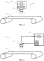
- FIG 3 shows an example, in which an operating principle of an inspection method of a machine vision system 30 is disclosed in conjunction with a moving object 33.
- the machine vision system comprises at least one smart camera 34 comprising an area image sensor 31 and an image data processing device part 32.
- the area image sensor 31 is arranged to expose image frames i.e. image matrixes from the moving object 33 and to transfer a part (i.e. synchronizing image area) of each image frame to the image data processing device part 32 of the smart camera 34.
- the image data processing device part 32 comprises at least one processor, at least one memory including computer program code for one or more program units, and means for receiving image data wirelessly or via wired connection, for example, a receiver or a transceiver and means for transferring trigger signals wirelessly or via wired connection, for example, a transmitter or a transceiver.
- processors e.g. a general purpose processor and a graphics processor and a DSP processor and/or multiple different memories e.g. volatile memory for storing data and programs at run-time and nonvolatile memory like a hard disk for permanently storing data and programs.
- the image data processing device part 32 of the smart camera 34 may be any computing device suitable for handling image data such as a computer.
- the image data processing device part 32 is in electronic communication with the area image sensor 31 via signal lines.
- the smart camera 34 may also include a video controller and an audio controller for generating signals that can be produced to the user with computer accessories.
- the smart camera 34 produces output to the user through output means.
- the video controller may be connected to a display.
- the display may be e.g. a flat panel display or a projector for producing a larger image.
- the audio controller may be connected to a sound source such as loudspeakers or earphones.
- the image data processing device part 32 is configured to receive from the area image sensor 31 a part of the image frame exposed by the area image sensor 31.
- the image data processing device part 32 analyses the above mentioned image frame part and if the image data processing device part 32 detects a predefined event, it may trigger the area image sensor 31 by indicating that a bigger part or the whole image frame must be transferred to the image data processing device part 32 for further analysis i.e. the image data processing device part 32 requests a larger part of the image frame (further analysis area) from the area image sensor 31. It is also possible that the image data processing device part 32 defines the size of the further analysis area to be transferred or the size may be predefined for the area image sensor 31.
- the image data processing device part 32 re-configures the area image sensor 31 so that the size and position of the bigger image area are dependent on conditions in the synchronizing image area, for example, so that the detected event is in the middle of the bigger image area i.e. the further analysis area.
- the number of image frames of which a bigger part is transmitted for further analysis may also be more than one.
- the camera After the area image sensor 31 has transferred the requested or predefined image data, the camera starts to transfer image frame parts until it receives the next trigger signal.
- the image data processing device part 32 may further be arranged to notify a user of the machine comprising the machine vision system 30.
- FIG 4 shows an example, in which an operating principle of an inspection method of a machine vision system 40 is disclosed in conjunction with a moving object to be monitored 43.
- the machine vision system comprises at least one area-scan camera (area image sensor) 41 and an image data processing device 42.
- the area-scan camera 41 is arranged to expose image frames i.e. image matrixes from the object to be monitored 43 and to transfer a part of each image frame to the image data processing device 42.
- the image data processing device 42 comprises at least one processor, at least one memory including computer program code for one or more program units, and means for receiving image data wirelessly or via wired connection, for example, a receiver or a transceiver and means for transferring trigger signals wirelessly or via wired connection, for example, a transmitter or a transceiver.
- processors e.g. a general purpose processor and a graphics processor and a DSP processor and/or multiple different memories e.g. volatile memory for storing data and programs at run-time and nonvolatile memory like a hard disk for permanently storing data and programs.
- the image data processing device 42 may be any computing device suitable for handling image data such as a computer.
- the image data processing device 42 is in electronic communication with the camera 41 via signal lines.
- the image data processing device 42 comprises I/O circuitry.
- the connection between the camera 41 and the image data processing device 42 is a wired or wireless network.
- the image data processing device 42 may also include a video controller and an audio controller for generating signals that can be produced to the user with computer accessories.
- the simulator produces output to the user through output means.
- the video controller may be connected to a display.
- the display may be e.g. a flat panel display or a projector for producing a larger image.
- the audio controller may be connected to a sound source such as loudspeakers or earphones.
- the image data processing device 42 is configured to receive from the camera 41 a part of the image data frame exposed by the camera 41.
- the image data processing device 42 analyses the above mentioned image area part and if the image data processing device 42 detects a predefined event, it forms a trigger signal and transmits it to the camera 41.
- the trigger signal indicates for the camera 41 that a bigger part or the whole image frame must be transferred to the image data processing device 42 for further analysis i.e. the image data processing device 42 requests a larger part of the image frame from the camera 41 by the trigger signal.
- the image data processing device 42 defines the size of the area to be transferred in the trigger signal or the size may be predefined for the camera 41.
- the image data processing device part 42 re-configures the camera 41 so that the size and position of the bigger image area are dependent on conditions in the synchronizing image area, for example so that the detected event is in the middle of the bigger image area i.e. the further analysis area.
- the number of image frames of which a bigger part is transmitted for further analysis may also be more than one.
- the camera 41 After the camera 41 has transferred the requested or predefined image data, the camera starts to transfer small image frame parts until it receives the next trigger signal.
- the image data processing device 42 is further arranged to notify a user of the machine comprising the machine vision system 40.
- Some modern cameras also offer the possibility of having multiple predetermined configuration sets, which if used can speed up the process of re-configuring the camera 41 to the different modes.
- predetermined configuration sets instead of a list of parameters, a simple command from the data processing device 42 will be enough to re-configure the camera 41.
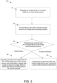
- FIG. 5 shows an example, in which a block diagram of an inspection method 50 of a machine vision system is disclosed.
- an image frame of a moving object to be monitored is exposed by an area image sensor.
- a part of the exposed image frame is transmitted to an image data processing device.
- the received part of an image frame is analysed by the image data processing device. If the received part of the image frame is detected to comprise a predefined event, in step 54, said area image sensor exposes at least one further image frame of the moving object and transmits a bigger part of said at least one further image frame to said image data processing device for further analysis. If the received part of an image frame is not detected to comprise a predefined event, in step 55, said area image sensor continues to expose at least one further image frame and to transmit a part of said at least one exposed image frame.
- a part of the image frame that is transmitted to an image data processing device may determine the size and/or position of said bigger part of the image frame, and/or the number of image frames of which a bigger part is transmitted. For example, conditions (size or placement etc.) of a predefined event in the part of the image frame may determine the size and/or position of said bigger part of the image frame, and/or the number of image frames of which a bigger part is transmitted.
- the image sensor is configured to transfer a bigger part of the first image frame after the detected event, whereas in some examples, the image sensor is configured to transfer a bigger part of the image frame after, for example, a predetermined number of image frames from the detected event.
- an apparatus that is a computing device, for example, an image data processing device may comprise circuitry and electronics for analysing, receiving and transmitting data, a computer program code in a memory, and a processor which, when running the computer program code, causes the apparatus to carry out the features of an example.
- the processor when running the computer program code may carry out all the steps of the following method: exposing an image frame of an object to be monitored by an area image sensor, transmitting a part of said exposed image frame, analysing the received part of said image frame, and if said received part of said image frame is detected to comprise at least one predefined event, said image data processing device is arranged to transmit a trigger signal to said area image sensor, and wherein said area image sensor is arranged to transmit a bigger part of said image frame to said image data processing device for further analysis, or if said received part of said image frame is not detected to comprise a predefined event, said area image sensor continues to expose at least one further image frame and to transmit a part of said at least one further image frame.
Landscapes
- Engineering & Computer Science (AREA)
- Physics & Mathematics (AREA)
- General Physics & Mathematics (AREA)
- Health & Medical Sciences (AREA)
- Life Sciences & Earth Sciences (AREA)
- Chemical & Material Sciences (AREA)
- General Health & Medical Sciences (AREA)
- Biochemistry (AREA)
- Pathology (AREA)
- Immunology (AREA)
- Analytical Chemistry (AREA)
- Signal Processing (AREA)
- Computer Vision & Pattern Recognition (AREA)
- Theoretical Computer Science (AREA)
- Multimedia (AREA)
- Textile Engineering (AREA)
- Quality & Reliability (AREA)
- Food Science & Technology (AREA)
- Medicinal Chemistry (AREA)
- Biomedical Technology (AREA)
- Investigating Materials By The Use Of Optical Means Adapted For Particular Applications (AREA)
- Studio Devices (AREA)
- Image Analysis (AREA)
- Closed-Circuit Television Systems (AREA)
- General Factory Administration (AREA)
- Image Processing (AREA)
Applications Claiming Priority (2)
| Application Number | Priority Date | Filing Date | Title |
|---|---|---|---|
| FI20135749A FI128403B (en) | 2013-07-05 | 2013-07-05 | Synchronizing image capture |
| PCT/FI2014/050564 WO2015001196A1 (en) | 2013-07-05 | 2014-07-07 | Synchronization of imaging |
Publications (4)
| Publication Number | Publication Date |
|---|---|
| EP3017425A1 EP3017425A1 (en) | 2016-05-11 |
| EP3017425A4 EP3017425A4 (en) | 2018-08-15 |
| EP3017425B1 true EP3017425B1 (en) | 2024-03-20 |
| EP3017425C0 EP3017425C0 (en) | 2024-03-20 |
Family
ID=52143169
Family Applications (1)
| Application Number | Title | Priority Date | Filing Date |
|---|---|---|---|
| EP14819582.9A Active EP3017425B1 (en) | 2013-07-05 | 2014-07-07 | Synchronization of imaging |
Country Status (7)
| Country | Link |
|---|---|
| US (1) | US9532015B2 (ko) |
| EP (1) | EP3017425B1 (ko) |
| JP (1) | JP2016532099A (ko) |
| KR (1) | KR102038181B1 (ko) |
| CN (1) | CN105917379B (ko) |
| FI (1) | FI128403B (ko) |
| WO (1) | WO2015001196A1 (ko) |
Families Citing this family (5)
| Publication number | Priority date | Publication date | Assignee | Title |
|---|---|---|---|---|
| US20160364525A1 (en) * | 2015-06-09 | 2016-12-15 | Toshiba Medical Systems Corporation | Medical image processing apparatus and medical image transfer system |
| FI20155643A (fi) | 2015-09-08 | 2017-03-09 | Procemex Oy Ltd | Fluoresoivan nesteen optinen havainnointi puukuiturainasta |
| FI128735B (en) * | 2016-05-06 | 2020-11-13 | Procemex Oy Ltd | Machine vision method and system |
| FI128850B (en) | 2016-05-06 | 2021-01-29 | Procemex Oy Ltd | Procedure for computer vision and systems for monitoring manufacturing processes |
| CN113445201B (zh) * | 2021-07-20 | 2022-09-27 | 大易智慧信息科技(苏州)有限公司 | 基于相机阵列的双针床经编机断丝在线检测系统及其方法 |
Family Cites Families (30)
| Publication number | Priority date | Publication date | Assignee | Title |
|---|---|---|---|---|
| JPH05240805A (ja) * | 1992-02-27 | 1993-09-21 | Kawasaki Steel Corp | 表面欠陥検査装置 |
| JPH1065940A (ja) * | 1996-06-13 | 1998-03-06 | Olympus Optical Co Ltd | 撮像装置 |
| JP3015325B2 (ja) * | 1996-06-26 | 2000-03-06 | 東芝エンジニアリング株式会社 | スジキズ検査方法及びその装置 |
| JPH1194760A (ja) * | 1997-09-24 | 1999-04-09 | Olympus Optical Co Ltd | 欠陥検出用顕微鏡 |
| US5935285A (en) * | 1997-12-30 | 1999-08-10 | Coors Brewing Company | Method for inspecting manufactured articles |
| US6947587B1 (en) * | 1998-04-21 | 2005-09-20 | Hitachi, Ltd. | Defect inspection method and apparatus |
| ES2182738T1 (es) | 1998-08-12 | 2003-03-16 | Honeywell Oy | Procedimiento y sistema para monitorizar una banda continua de papel, pulpa de papel o un hilo que se desplaza en una maquina de papel. |
| FI990159A (fi) | 1999-01-28 | 2000-07-29 | Valmet Automation Inc | Menetelmä kuiturainan laadun valvomiseksi |
| FI114741B (fi) * | 2001-05-11 | 2004-12-15 | Metso Automation Oy | Lämpökuvaukseen perustuva laadun- ja kunnonvalvontamenetelmä |
| DE10260464A1 (de) | 2002-12-21 | 2004-07-01 | Voith Paper Patent Gmbh | Verfahren und Vorrichtung zum Betreiben einer Maschine zum Herstellen und/oder Veredeln einer Materialbahn |
| US7027934B2 (en) * | 2003-09-24 | 2006-04-11 | 3M Innovative Properties Company | Apparatus and method for automated web inspection |
| US20050117017A1 (en) | 2003-12-01 | 2005-06-02 | Baer Richard L. | System and method for imaging regions of interest |
| JP2005308464A (ja) * | 2004-04-20 | 2005-11-04 | Dainippon Screen Mfg Co Ltd | 欠陥検出装置および欠陥検出方法 |
| EP1630550A1 (en) | 2004-08-27 | 2006-03-01 | Moller & Devicon A/S | Methods and apparatuses of detecting foreign particles or faults in a plurality of filled containers |
| US20080225130A1 (en) * | 2004-12-23 | 2008-09-18 | Nokia Corporation | Method for Extracting of Multiple Sub-Windows of a Scanning Area by Means of a Digital Video Camera |
| EP1897495A4 (en) * | 2005-06-28 | 2011-01-05 | Konica Minolta Med & Graphic | METHOD FOR THE DETECTION OF ANOMALIC SHADE CANDIDATES, DEVICE FOR DETECTING ANOMALIC SHADE CANDIDATES |
| JP2007049673A (ja) * | 2005-07-13 | 2007-02-22 | Ricoh Co Ltd | 画像読み取り装置、画像形成装置、画像検査装置及び画像形成システム |
| JP2007240432A (ja) * | 2006-03-10 | 2007-09-20 | Omron Corp | 欠陥検査装置および欠陥検査方法 |
| US8014586B2 (en) * | 2007-05-24 | 2011-09-06 | Applied Vision Corporation | Apparatus and methods for container inspection |
| EP2162734A1 (de) * | 2007-07-04 | 2010-03-17 | Thermosensorik Gmbh | Verfahren zur automatischen inspektion einer schweissnaht mittels wärmefluss-thermographie |
| EP2315020B1 (en) * | 2008-07-18 | 2019-07-24 | Tohoku University | Method for imaging a structure defect and device for imaging a structure defect |
| AT508159B1 (de) | 2009-06-05 | 2010-11-15 | Starlinger & Co Gmbh | Fehlerstellenerkennung |
| US20110141269A1 (en) | 2009-12-16 | 2011-06-16 | Stephen Michael Varga | Systems And Methods For Monitoring On-Line Webs Using Line Scan Cameras |
| US8345949B2 (en) * | 2010-03-09 | 2013-01-01 | General Electric Company | Sequential approach for automatic defect recognition |
| FR2978831A1 (fr) * | 2011-08-05 | 2013-02-08 | St Microelectronics Sa | Detection de defauts par imagerie thermique frequentielle. |
| US20120293623A1 (en) * | 2011-05-17 | 2012-11-22 | Gii Acquisition, Llc Dba General Inspection, Llc | Method and system for inspecting small manufactured objects at a plurality of inspection stations and sorting the inspected objects |
| JP2013190309A (ja) * | 2012-03-13 | 2013-09-26 | Toshiba Corp | 欠陥検査装置 |
| JP5944189B2 (ja) * | 2012-03-15 | 2016-07-05 | 株式会社東芝 | マスク基板の欠陥検査方法及び欠陥検査装置、フォトマスクの製造方法及び半導体装置の製造方法 |
| US9390491B2 (en) * | 2013-01-30 | 2016-07-12 | Taiwan Semiconductor Manufacturing Co., Ltd. | System and method for automatic quality control for assembly line processes |
| JP6241052B2 (ja) * | 2013-03-29 | 2017-12-06 | オムロン株式会社 | 画像処理システムおよび画像処理プログラム |
-
2013
- 2013-07-05 FI FI20135749A patent/FI128403B/en active IP Right Grant
-
2014
- 2014-07-07 CN CN201480038286.0A patent/CN105917379B/zh active Active
- 2014-07-07 WO PCT/FI2014/050564 patent/WO2015001196A1/en active Application Filing
- 2014-07-07 KR KR1020157036631A patent/KR102038181B1/ko active IP Right Grant
- 2014-07-07 JP JP2016522686A patent/JP2016532099A/ja active Pending
- 2014-07-07 US US14/902,852 patent/US9532015B2/en active Active
- 2014-07-07 EP EP14819582.9A patent/EP3017425B1/en active Active
Non-Patent Citations (1)
| Title |
|---|
| WILLIAM ROBERT HAAS ET AL: "Automatic image capture method for a digital camera", RESEARCH DISCLOSURE, KENNETH MASON PUBLICATIONS, HAMPSHIRE, UK, GB, vol. 497, no. 81, 1 September 2005 (2005-09-01), XP007135476, ISSN: 0374-4353 * |
Also Published As
| Publication number | Publication date |
|---|---|
| FI20135749A (fi) | 2015-01-06 |
| FI128403B (en) | 2020-04-30 |
| WO2015001196A1 (en) | 2015-01-08 |
| US20160142682A1 (en) | 2016-05-19 |
| US9532015B2 (en) | 2016-12-27 |
| CN105917379A (zh) | 2016-08-31 |
| KR20160030116A (ko) | 2016-03-16 |
| EP3017425A4 (en) | 2018-08-15 |
| EP3017425A1 (en) | 2016-05-11 |
| JP2016532099A (ja) | 2016-10-13 |
| KR102038181B1 (ko) | 2019-10-30 |
| EP3017425C0 (en) | 2024-03-20 |
| CN105917379B (zh) | 2019-10-11 |
Similar Documents
| Publication | Publication Date | Title |
|---|---|---|
| EP3017425B1 (en) | Synchronization of imaging | |
| EP3452806B1 (en) | A machine vision method and system | |
| KR100989081B1 (ko) | 네트워크 카메라를 이용한 이벤트 감시 시스템 및 방법 | |
| US20050137827A1 (en) | System and method for managing arrangement position and shape of device | |
| KR101179131B1 (ko) | 팬/틸트/줌 기능 일체형 동시감시카메라를 이용한 감시시스템 | |
| US11032477B2 (en) | Motion stabilized image sensor, camera module and apparatus comprising same | |
| US20230228691A1 (en) | Smart synchronization method of a web inspection system | |
| EP2710511A1 (en) | Image processing system and related monitoring system | |
| WO2020141253A1 (en) | A method of using a machine-readable code for instructing camera for detecting and monitoring objects | |
| US20170371035A1 (en) | Protection and guidance gear or equipment with identity code and ip address | |
| EP3700199A1 (en) | Data transmission method, camera and electronic device | |
| KR101441755B1 (ko) | 이미지센서모듈 및 메인프로세싱모듈이 교체 가능한 스마트 카메라 | |
| US20190116341A1 (en) | Smart sensor apparatus | |
| JP4997430B2 (ja) | 撮像映像送信装置及び撮像映像送信方法 | |
| CN116033090A (zh) | 一种基于多相机的图像采集控制方法及控制装置 | |
| JP2003331373A5 (ko) | ||
| Faigl et al. | Camera Module for Onboard Relative Localization in SWARM of robots | |
| Heimgartner | Autonomous multisensor tracking surveillance system | |
| JP2006051675A (ja) | 成形監視システム及び成形監視方法 | |
| JP2008054041A (ja) | 撮像素子検査装置 |
Legal Events
| Date | Code | Title | Description |
|---|---|---|---|
| PUAI | Public reference made under article 153(3) epc to a published international application that has entered the european phase |
Free format text: ORIGINAL CODE: 0009012 |
|
| 17P | Request for examination filed |
Effective date: 20151229 |
|
| AK | Designated contracting states |
Kind code of ref document: A1 Designated state(s): AL AT BE BG CH CY CZ DE DK EE ES FI FR GB GR HR HU IE IS IT LI LT LU LV MC MK MT NL NO PL PT RO RS SE SI SK SM TR |
|
| AX | Request for extension of the european patent |
Extension state: BA ME |
|
| DAX | Request for extension of the european patent (deleted) | ||
| A4 | Supplementary search report drawn up and despatched |
Effective date: 20180716 |
|
| RIC1 | Information provided on ipc code assigned before grant |
Ipc: H04N 1/00 20060101ALI20180710BHEP Ipc: G06T 7/00 20060101AFI20180710BHEP Ipc: G01N 21/88 20060101ALI20180710BHEP Ipc: G01N 21/89 20060101ALI20180710BHEP |
|
| STAA | Information on the status of an ep patent application or granted ep patent |
Free format text: STATUS: EXAMINATION IS IN PROGRESS |
|
| 17Q | First examination report despatched |
Effective date: 20200331 |
|
| STAA | Information on the status of an ep patent application or granted ep patent |
Free format text: STATUS: EXAMINATION IS IN PROGRESS |
|
| STAA | Information on the status of an ep patent application or granted ep patent |
Free format text: STATUS: EXAMINATION IS IN PROGRESS |
|
| RIC1 | Information provided on ipc code assigned before grant |
Ipc: G01N 21/88 20060101ALI20230925BHEP Ipc: G01N 21/89 20060101ALI20230925BHEP Ipc: G01N 33/34 20060101ALI20230925BHEP Ipc: D21G 9/00 20060101ALI20230925BHEP Ipc: G06T 7/00 20060101AFI20230925BHEP |
|
| GRAP | Despatch of communication of intention to grant a patent |
Free format text: ORIGINAL CODE: EPIDOSNIGR1 |
|
| STAA | Information on the status of an ep patent application or granted ep patent |
Free format text: STATUS: GRANT OF PATENT IS INTENDED |
|
| INTG | Intention to grant announced |
Effective date: 20231122 |
|
| GRAS | Grant fee paid |
Free format text: ORIGINAL CODE: EPIDOSNIGR3 |
|
| GRAA | (expected) grant |
Free format text: ORIGINAL CODE: 0009210 |
|
| STAA | Information on the status of an ep patent application or granted ep patent |
Free format text: STATUS: THE PATENT HAS BEEN GRANTED |
|
| AK | Designated contracting states |
Kind code of ref document: B1 Designated state(s): AL AT BE BG CH CY CZ DE DK EE ES FI FR GB GR HR HU IE IS IT LI LT LU LV MC MK MT NL NO PL PT RO RS SE SI SK SM TR |
|
| REG | Reference to a national code |
Ref country code: GB Ref legal event code: FG4D |
|
| REG | Reference to a national code |
Ref country code: CH Ref legal event code: EP |
|
| REG | Reference to a national code |
Ref country code: DE Ref legal event code: R096 Ref document number: 602014089739 Country of ref document: DE |
|
| REG | Reference to a national code |
Ref country code: IE Ref legal event code: FG4D |
|
| U01 | Request for unitary effect filed |
Effective date: 20240411 |
|
| U07 | Unitary effect registered |
Designated state(s): AT BE BG DE DK EE FI FR IT LT LU LV MT NL PT SE SI Effective date: 20240418 |
|
| PG25 | Lapsed in a contracting state [announced via postgrant information from national office to epo] |
Ref country code: GR Free format text: LAPSE BECAUSE OF FAILURE TO SUBMIT A TRANSLATION OF THE DESCRIPTION OR TO PAY THE FEE WITHIN THE PRESCRIBED TIME-LIMIT Effective date: 20240621 |
|
| PG25 | Lapsed in a contracting state [announced via postgrant information from national office to epo] |
Ref country code: RS Free format text: LAPSE BECAUSE OF FAILURE TO SUBMIT A TRANSLATION OF THE DESCRIPTION OR TO PAY THE FEE WITHIN THE PRESCRIBED TIME-LIMIT Effective date: 20240620 Ref country code: HR Free format text: LAPSE BECAUSE OF FAILURE TO SUBMIT A TRANSLATION OF THE DESCRIPTION OR TO PAY THE FEE WITHIN THE PRESCRIBED TIME-LIMIT Effective date: 20240320 |
|
| U20 | Renewal fee paid [unitary effect] |
Year of fee payment: 11 Effective date: 20240617 |
|
| PG25 | Lapsed in a contracting state [announced via postgrant information from national office to epo] |
Ref country code: RS Free format text: LAPSE BECAUSE OF FAILURE TO SUBMIT A TRANSLATION OF THE DESCRIPTION OR TO PAY THE FEE WITHIN THE PRESCRIBED TIME-LIMIT Effective date: 20240620 Ref country code: NO Free format text: LAPSE BECAUSE OF FAILURE TO SUBMIT A TRANSLATION OF THE DESCRIPTION OR TO PAY THE FEE WITHIN THE PRESCRIBED TIME-LIMIT Effective date: 20240620 Ref country code: HR Free format text: LAPSE BECAUSE OF FAILURE TO SUBMIT A TRANSLATION OF THE DESCRIPTION OR TO PAY THE FEE WITHIN THE PRESCRIBED TIME-LIMIT Effective date: 20240320 Ref country code: GR Free format text: LAPSE BECAUSE OF FAILURE TO SUBMIT A TRANSLATION OF THE DESCRIPTION OR TO PAY THE FEE WITHIN THE PRESCRIBED TIME-LIMIT Effective date: 20240621 |