EP3017263B1 - Feuerwaffe - Google Patents
Feuerwaffe Download PDFInfo
- Publication number
- EP3017263B1 EP3017263B1 EP14726503.7A EP14726503A EP3017263B1 EP 3017263 B1 EP3017263 B1 EP 3017263B1 EP 14726503 A EP14726503 A EP 14726503A EP 3017263 B1 EP3017263 B1 EP 3017263B1
- Authority
- EP
- European Patent Office
- Prior art keywords
- ejector
- barrel
- cartridge
- slide
- carriage
- Prior art date
- Legal status (The legal status is an assumption and is not a legal conclusion. Google has not performed a legal analysis and makes no representation as to the accuracy of the status listed.)
- Not-in-force
Links
Images


Classifications
-
- F—MECHANICAL ENGINEERING; LIGHTING; HEATING; WEAPONS; BLASTING
- F41—WEAPONS
- F41A—FUNCTIONAL FEATURES OR DETAILS COMMON TO BOTH SMALLARMS AND ORDNANCE, e.g. CANNONS; MOUNTINGS FOR SMALLARMS OR ORDNANCE
- F41A11/00—Assembly or disassembly features; Modular concepts; Articulated or collapsible guns
- F41A11/02—Modular concepts, e.g. weapon-family concepts
-
- F—MECHANICAL ENGINEERING; LIGHTING; HEATING; WEAPONS; BLASTING
- F41—WEAPONS
- F41A—FUNCTIONAL FEATURES OR DETAILS COMMON TO BOTH SMALLARMS AND ORDNANCE, e.g. CANNONS; MOUNTINGS FOR SMALLARMS OR ORDNANCE
- F41A15/00—Cartridge extractors, i.e. devices for pulling cartridges or cartridge cases at least partially out of the cartridge chamber; Cartridge ejectors, i.e. devices for throwing the extracted cartridges or cartridge cases free of the gun
- F41A15/12—Cartridge extractors, i.e. devices for pulling cartridges or cartridge cases at least partially out of the cartridge chamber; Cartridge ejectors, i.e. devices for throwing the extracted cartridges or cartridge cases free of the gun for bolt-action guns
- F41A15/14—Cartridge extractors, i.e. devices for pulling cartridges or cartridge cases at least partially out of the cartridge chamber; Cartridge ejectors, i.e. devices for throwing the extracted cartridges or cartridge cases free of the gun for bolt-action guns the ejector being mounted on or within the bolt; Extractors per se
-
- F—MECHANICAL ENGINEERING; LIGHTING; HEATING; WEAPONS; BLASTING
- F41—WEAPONS
- F41A—FUNCTIONAL FEATURES OR DETAILS COMMON TO BOTH SMALLARMS AND ORDNANCE, e.g. CANNONS; MOUNTINGS FOR SMALLARMS OR ORDNANCE
- F41A15/00—Cartridge extractors, i.e. devices for pulling cartridges or cartridge cases at least partially out of the cartridge chamber; Cartridge ejectors, i.e. devices for throwing the extracted cartridges or cartridge cases free of the gun
- F41A15/12—Cartridge extractors, i.e. devices for pulling cartridges or cartridge cases at least partially out of the cartridge chamber; Cartridge ejectors, i.e. devices for throwing the extracted cartridges or cartridge cases free of the gun for bolt-action guns
- F41A15/16—Cartridge extractors, i.e. devices for pulling cartridges or cartridge cases at least partially out of the cartridge chamber; Cartridge ejectors, i.e. devices for throwing the extracted cartridges or cartridge cases free of the gun for bolt-action guns the ejector being mounted on the breech housing or frame
-
- F—MECHANICAL ENGINEERING; LIGHTING; HEATING; WEAPONS; BLASTING
- F41—WEAPONS
- F41A—FUNCTIONAL FEATURES OR DETAILS COMMON TO BOTH SMALLARMS AND ORDNANCE, e.g. CANNONS; MOUNTINGS FOR SMALLARMS OR ORDNANCE
- F41A21/00—Barrels; Gun tubes; Muzzle attachments; Barrel mounting means
- F41A21/48—Barrel mounting means, e.g. releasable mountings for replaceable barrels
-
- F—MECHANICAL ENGINEERING; LIGHTING; HEATING; WEAPONS; BLASTING
- F41—WEAPONS
- F41A—FUNCTIONAL FEATURES OR DETAILS COMMON TO BOTH SMALLARMS AND ORDNANCE, e.g. CANNONS; MOUNTINGS FOR SMALLARMS OR ORDNANCE
- F41A3/00—Breech mechanisms, e.g. locks
- F41A3/64—Mounting of breech-blocks; Accessories for breech-blocks or breech-block mountings
- F41A3/66—Breech housings or frames; Receivers
Definitions
- the present invention relates to a firearm comprising a component carrier, a barrel having a cartridge chamber for receiving a cartridge, and a slide longitudinally slidably mounted on the component carrier having a closure for the barrel and a cartridge knock-off means, the carriage comprising an extractor for withdrawing a severed cartridge carries from the cartridge chamber and the ejector is mounted longitudinally displaceable on the carriage, which projects into the pull-out movement path of the cartridge from the side and in the final phase of the backward movement of the carriage rests against a formed on the component carrier stop.
- a firearm of this kind is from the EP 1 363 099 A1 known.
- the extractor cooperates with the ejector, against which the cartridge pushes laterally with its cartridge bottom when pulling out, whereby it is tilted and ejected, for example by a side window or a recess of the carriage.
- the ejector must be adapted to the caliber of the cartridge used in order to project into the path of movement of the cartridge to the correct extent and thus to cause their tilting.
- the barrel (or at least its cartridge bearing) is exchanged for a smaller caliber, also changes due to the reduced cartridge diameter and / or the different barrel the point of application of the ejector, which can lead to malfunction.
- FX cartridges color marking cartridges
- the invention has as its object to solve this problem and to provide a firearm with improved function for use with different ammunition.
- a firearm of the type mentioned in the introduction which is characterized according to the invention in that the entire carriage can be exchanged together with the ejector modular against a ejector second slide, for which said stop takes over the ejector.
- the weapon thus has a rigid "replacement" ejector in the form of the stop on the component carrier.
- a particularly advantageous embodiment of the invention is characterized in that the ejector has an elongated central portion which slides on the stop, and a hook-shaped end portion which rests against the stop in said end phase.
- the ejector need only be longitudinally displaceable in the carriage by at least that displacement distance which corresponds to the final phase of the pull-out movement in which the extractor pulls the cartridge further back at one edge of its cartridge bottom while the cartridge bottom abuts the fixed ejector at the opposite edge, ie the tilting path of the cartridge bottom. If desired, however, the ejector can also be displaceable over a longer displacement distance in the carriage. Preferably, the ejector is acted upon by a spring relative to the carriage to the rear, ie after rear resiliently biased so that it moves during the forward movement of the carriage in a cartridge as unimpaired position.
- the barrel is a removable barrel.
- a first run may e.g. be a rigid barrel, which is modular exchangeable against a tilted mounted second barrel.
- this results in an advantageous modular weapon system in which e.g. on the one hand, a tiltable barrel for high-energy ammunition with an ejector-free slide with interlocking closure or on the other hand, a rigid barrel for small caliber or FX ammunition with an ejector slide interacts with ground closure.
- the weapon has a housing divided into a lower part and an upper part, wherein the component carrier lies in the lower housing part and the carriage forms the upper housing part.
- Fig. 1 and 2 briefly explains the operation of a cooperating with an ejector extractor in a firearm.
- a severed cartridge 1 ("empty cartridge case") is withdrawn from an extractor 2 in the direction of arrow F backwards out of the rear part or cartridge chamber 3 of a barrel 4 (only partially shown).
- the extractor 2 engages with a hook-shaped part 5 laterally in a groove 6 next to the cartridge bottom 7 of the cartridge 1 a.
- an ejector 9 where the severed cartridge 1 in the final phase
- a firearm 11 or parts thereof shown are a firearm 11 or parts thereof shown.
- the firearm 11 is in the present case a pistol, but it is understood that the firearm 11 may also be a long gun, such as a hunting or assault rifle.
- the firearm 11 comprises a housing lower part 12 and a housing upper part 13.
- the housing lower part 12 contains a component carrier 14 (FIG. Fig. 5 . 7a ) preferably of metal, which stores the shot-relevant components and in their relative positions to each other, such as a barrel 15, a cooperating closure 16 and (not shown) a knock-off device for the cartridge 1, a discharge device for the knock-down device and a magazine, as known in the art.
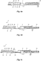
- the closure 16 is mounted in a carriage 17, which is mounted for example on dovetail guides 18, 19 on the component carrier 14 in the longitudinal direction of the weapon 11 (weft direction of the barrel 15) longitudinally displaceable, see Fig. 6a to 6c ,
- the locking of the closure 16 with the barrel 15 is not shown in detail and may be done in any manner known in the art.
- the barrel 15 is a controlled tilting barrel which tilts down a few millimeters after the firing at its rear end to release a latching connection with the closure 16.
- the carriage 17 may include a rotary piston closure.
- the carriage 17 is designed in the form of a housing 15, which also covers the barrel 15, and contains the closure 16; Alternatively, the carriage 17 may also directly form the closure 16 or be integrated with this and do not cover the barrel 15.
- the component distribution of the housing base 12 may be different than illustrated, for example, the component carrier 14 itself may form the housing base 12, i. be integral with this.
- the choice of material is arbitrary, for example, some or all of the parts can be made as far as possible from inexpensive plastic instead of metal.
- the barrel 15 is preferably exchangeable modularly against a Tnlechsellholz another caliber or at least with (not shown) adapter rings for narrowing the cartridge chamber 3 for a small caliber training ammunition equipped.
- a first, rigid barrel 15 may be used for small caliber training ammunition or FX cartridges, along with an unlatched closure ("ground-lock") against a second, tilted ("controlled") barrel for large-caliber cartridge ammunition can be changed, which cooperates in the manner mentioned with a lockable closure 16.
- the entire upper housing part 13 with the closure 16 and the barrel 15 can be changed, while the lower housing part 12 with magazine, trigger device, clamping device, etc. remains the same.
- an ejector 9 is used, which is movably mounted in the carriage 17.
- the ejector 9 slides with lateral tabs 20 in longitudinal guides 21 of the carriage 17 and is between a first, relative to the carriage 17 to the rear offset position ( Fig. 6a, 6b . 7a, 7b ) and a second, relative to the carriage 17 by the way d forward offset position ( Fig. 6c ) movably mounted.
- a compression spring 22 between an inner shoulder of the carriage 17 and, for example, one of the tabs 20 biases the ejector 9 in the rear position ( Fig. 6a, 6b . 7a, 7b ) in front. This is advantageous, but not mandatory, if necessary, the compression spring 22 can also be omitted.
- the ejector 9 moves first with the carriage 17.
- the ejector 9 is fixed relative to the component carrier 14, by the ejector 9 abuts against a formed on the component carrier 14 stop 23.
- a hook-shaped front end portion 24 of the ejector 9 comes to the front end of the stop 23 to the plant.
- the ejector 9 is thereby stopped, while the carriage 17 continues to move rearward about the path d, whereby the ejector 9 with respect to the carriage 16 projects forward ( Fig. 6c ) and an ejector function as in Fig. 2 shown to eject the cartridge 1.
- the ejector 9 also abut against a stop 23 at another location of the component carrier 14 could, for example, with its rear end to a further behind arranged stop 23.
- the ejector 9 could then be made much shorter than shown.
- the illustrated embodiment with a very elongated, far forward projecting far and provided with a hook end ejector 9 has the advantage that it can cooperate with a very far forward stop 23, which can assume such a dual function: When the carriage 17 and Housing upper part 13 is removed with the ejector 9 and replaced by an "ejector" slide (not shown), the far forward stop 23 at the same time the function of a "conventional" rigid ejector 9 according to Fig. 2 take.
- the ejectorless slide 17 and the stopper 23 as a replacement ejector can eg combined with a barrel 15 for large caliber ammunition or a tiltable lockable barrel 15 for high energy ammunition; and a carriage 17 equipped with a movable ejector 9, e.g. with a barrel 15 for small caliber or training ammo.
- the stopper 23 has approximately triangular shape in section and the ejector 9 is formed on its side facing the stop 23 in the form of a triangular groove, so that the ejector 9 can be easily placed from above or in the longitudinal direction of the stop 23 and then rail-shaped on this led, what the change of the Schlittens 17 simplified.
- the ejector 9 in the carriage 17 can also be carried out only as a movable bolt or pin, which in the final phase of the carriage movement by the movement path d relative to the carriage 17 to the tilting movement ( Fig. 2 ).
- the ejector 9 can come into abutment against any stop 23 formed on the component carrier 14 or lower housing part 12.
Landscapes
- Engineering & Computer Science (AREA)
- General Engineering & Computer Science (AREA)
- Toys (AREA)
- Casting Support Devices, Ladles, And Melt Control Thereby (AREA)
- Bedding Items (AREA)
- Thermotherapy And Cooling Therapy Devices (AREA)
Description
- Die vorliegende Erfindung betrifft eine Feuerwaffe, umfassend einen Komponententräger, einen Lauf mit einem Patronenlager zur Aufnahme einer Patrone und einen am Komponententräger längsverschieblich gelagerten Schlitten mit einem Verschluss für den Lauf und einer Abschlageinrichtung für die Patrone, wobei der Schlitten einen Auszieher zum Ausziehen einer abgeschlagenen Patrone aus dem Patronenlager trägt und am Schlitten ein Auswerfer längsverschieblich gelagert ist, welcher in die Auszieh-Bewegungsbahn der Patrone von der Seite her hineinragt und in der Endphase der Rückwärtsbewegung des Schlittens an einem am Komponententräger ausgebildeten Anschlag anliegt.
- Eine Feuerwaffe dieser Art ist aus der
EP 1 363 099 A1 bekannt. Der Auszieher arbeitet mit dem Auswerfer (Ausstoßer) zusammen, gegen welchen die Patrone beim Ausziehen mit ihrem Patronenboden seitlich stößt, wodurch sie verkippt und ausgeworfen wird, z.B. durch ein seitliches Fenster oder eine Aussparung des Schlittens. Der Auswerfer muss dabei an das Kaliber der verwendeten Patrone angepasst sein, um im richtigen Ausmaß in die Bewegungsbahn der Patrone hineinzuragen und so ihr Verkippen zu bewirken. Bei derEP 1 363 099 A1 bewegt sich der Auswerfer während der Ausziehbewegung der Patrone mit dem Schlitten mit, bis er in der Endphase der Ausziehbewegung an der Rückwand des Komponententrägers der Waffe ansteht und dadurch seine Funktion als in die Bewegungsbahn der Patrone hineinragender, die Patrone verkippender Auswerfer erlangt. - Bei Waffen mit Wechselsystemen, bei welchen zum Verschießen z.B. von Kleinkaliber- oder Farbmarkierungspatronen (FX-Patronen) für Trainingszwecke der Lauf (oder zumindest sein Patronlager) gegen ein kleineres Kaliber getauscht wird, verändert sich durch den verringerten Patronendurchmesser und/oder den andersartigen Lauf auch der Angriffspunkt des Auswerfers, was zu Fehlfunktionen führen kann.
- Die Erfindung setzt sich zum Ziel, dieses Problem zu lösen und eine Feuerwaffe mit verbesserter Funktion für Verwendung mit unterschiedlicher Munition zu schaffen.
- Dieses Ziel wird mit einer Feuerwaffe der einleitend genanten Art erreicht, welche sich gemäß der Erfindung dadurch auszeichnet, dass der ganze Schlitten mitsamt dem Auswerfer modular gegen einen auswerferlosen zweiten Schlitten ausgetauscht werden kann, für welchen der genannte Anschlag die Auswerferfunktion übernimmt. Bei Verwendung eines auswerferlosen Schlittens hat die Waffe damit einen starren "Ersatz"-Auswerfer in Form des Anschlags am Komponententräger. Durch bloßes Austauschen des Schlittens bzw. Gehäuseoberteils, einmal mit und einmal ohne Auswerfer, kann somit in Verbindung mit verschiedenen Läufen (oder Patronenlagern) ein Wechselsystem für unterschiedliche Munition geschaffen werden, wobei die Auswerferfunktion immer optimal an den Durchmesser und die Auszieh-Bewegungsbahn der Patrone angepasst ist. Bevorzugt ist dazu auch der Auswerfer modular austauschbar im Schlitten gelagert.
- Eine besonders vorteilhafte Ausführungsform der Erfindung zeichnet sich dadurch aus, dass der Auswerfer einen langgestreckten Mittelabschnitt hat, der auf dem Anschlag gleitet, und einen hakenförmigen Endabschnitt, welcher in der genannten Endphase am Anschlag anliegt. Dadurch kann der Schlitten mit dem Auswerfer einfach von oben oder gleitend von vorne auf den Komponententräger mit dem Anschlag aufgesetzt werden.
- Der Auswerfer braucht im Schlitten lediglich mindestens um jene Verschiebedistanz längsverschieblich sein, welche der Endphase der Ausziehbewegung entspricht, in der der Auszieher die Patrone an einem Rand ihres Patronenbodens noch weiter nach hinten zieht, während der Patronenboden am gegenüberliegenden Rand am festgesetzten Auswerfer anliegt, d.h. um den Kippweg des Patronenbodens. Falls gewünscht, kann der Auswerfer jedoch auch über eine längere Verschiebedistanz im Schlitten verschieblich sein. Bevorzugt wird der Auswerfer durch eine Feder gegenüber dem Schlitten nach hinten beaufschlagt, d.h. nach hinten federnd vorgespannt, so dass er sich bei der Vorwärtsbewegung des Schlittens in eine die Patrone möglichst unbeeinträchtigende Stellung bewegt.
- Gemäß einer weiteren Ausführungsform der Erfindung ist der Lauf ein Wechsellauf. Ein erster Lauf kann z.B. ein starrer Lauf sein, der modular gegen einen abkippbar gelagerten zweiten Lauf austauschbar ist. In Verbindung mit einem modular austauschbaren Schlitten ergibt dies ein vorteilhaftes modulares Waffensystem, bei welchem z.B. einerseits ein abkippbarer Lauf für hochenergetische Munition mit einem auswerferlosen Schlitten mit verriegelndem Verschluss oder andererseits ein starrer Lauf für Kleinkaliber- oder FX-Munition mit einem Auswerfer-Schlitten mit Masseverschluss zusammenwirkt.
- In jedem Fall ist besonders günstig, wenn die Waffe ein in einen Unterteil und einen Oberteil geteiltes Gehäuse hat, wobei der Komponententräger im Gehäuseunterteil liegt und der Schlitten den Gehäuseoberteil bildet. Dadurch wird ein modulares Wechselsystem geschaffen, bei welchem der Waffenunterteil immer gleich bleiben und mit verschiedenen Schlitten und Läufen für unterschiedliche Munition kombiniert werden kann.
- Die Erfindung wird nachstehend anhand eines in den beigeschlossenen Zeichnung dargestellten Ausführungsbeispiels näher erläutert. In den Zeichnungen zeigen:
- die
Fig. 1 und 2 das Funktionsprinzip eines Auswerfers schematisch im Schnitt; - die
Fig. 3 und 4 den Gehäuseoberteil einer Feuerwaffe gemäß der Erfindung in einer Draufsicht (Fig. 3 ) und einem Querschnitt auf Höhe des Ausziehers und Auswerfers (Fig. 4 ); -
Fig. 5 eine teilweise Rückansicht der Feuerwaffe der Erfindung bei abgenommenem Gehäuseoberteil; - die
Fig. 6a bis 6c jeweils einen Längsschnitt durch den Gehäuseoberteil vonFig. 3 mit Lauf entlang der Schnittlinie A-A vonFig. 3 in drei verschiedenen Betriebsstellungen; - die
Fig. 7a und 7b eine Seitenansicht bzw. teilweise Seitenansicht der Feuerwaffe der Erfindung mit abgenommenem Gehäuseoberteil in zwei verschiedenen, den Betriebsstellungen derFig. 6a und 6b entsprechenden Betriebsstellungen; und -
Fig. 8 eine teilweise Seitenansicht der Feuerwaffe der Erfindung in einer Verwendungsstellung für einen auswerferlosen Schlitten. - Anhand der
Fig. 1 und 2 wird kurz die Funktionsweise eines mit einem Auswerfer zusammenwirkenden Ausziehers in einer Feuerwaffe erläutert. Nach der Schussabgabe wird eine abgeschlagene Patrone 1 ("leere Patronenhülse") von einem Auszieher 2 in Richtung des Pfeils F rückwärts aus dem hinteren Teil bzw. Patronenlager 3 eines (nur ausschnittsweise dargestellten) Laufes 4 herausgezogen. Der Auszieher 2 greift dabei mit einem hakenförmigen Teil 5 seitlich in eine Rille 6 neben dem Patronboden 7 der Patrone 1 ein. In die Bewegungsbahn 8 der Patrone 1 beim Herausziehen ragt seitlich ein Auswerfer 9, an welchem die abgeschlagene Patrone 1 in der Endphase (Fig. 2 ) ihrer Ausziehbewegung an einem Punkt P etwa gegenüber dem Angriffspunkt des Ausziehers 2 anschlägt, bei der weiteren Bewegung des Ausziehers 2 in Richtung des Pfeils F verkippt und so in Richtung des Pfeils E ausgeworfen wird, z.B. über ein seitliches Fenster 10 (Fig. 3 ) der Feuerwaffe. - Bei Verwendung unterschiedlicher Munition, d.h. Patronen 1 mit verschiedenen Durchmesser bzw. Kalibern, für welche z.B. Wechselläufe unterschiedlichen Kalibers verwendet werden, verlagert sich der Angriffspunkt P des Auswerfers 9, was zu Fehlfunktionen führen kann. Um dies zu lösen, dienen die im Folgenden dargestellten Maßnahmen.
- In den
Fig. 3 bis 8 sind eine Feuerwaffe 11 bzw. Teile davon dargestellt. Die Feuerwaffe 11 ist im vorliegenden Fall eine Pistole, es versteht sich jedoch, dass die Feuerwaffe 11 auch eine Langwaffe sein kann, z.B. ein Jagd- oder Sturmgewehr. - Die Feuerwaffe 11 umfasst einen Gehäuseunterteil 12 und einen Gehäuseoberteil 13. Der Gehäuseunterteil 12 enthält einen Komponententräger 14 (
Fig. 5 ,7a ) bevorzugt aus Metall, der die schussrelevanten Komponenten lagert und in ihren Relativlagen zueinander definiert, wie einen Lauf 15, einen damit zusammenwirkenden Verschluss 16 und (nicht dargestellt) eine Abschlageinrichtung für die Patrone 1, eine Abzugseinrichtung für die Abschlageinrichtung und ein Magazin, wie in der Technik bekannt. - Der Verschluss 16 ist in einem Schlitten 17 montiert, welcher z.B. über Schwalbenschwanzführungen 18, 19 auf dem Komponententräger 14 in Längsrichtung der Waffe 11 (Schussrichtung des Laufs 15) längsverschieblich gelagert ist, siehe
Fig. 6a bis 6c . Die Verriegelung des Verschlusses 16 mit dem Lauf 15 ist nicht im Detail gezeigt und kann auf jede in der Technik bekannte Arten erfolgen. Beispielsweise ist der Lauf 15 ein gesteuerter Kipplauf, der nach der Schussabgabe an seinem hinteren Ende um wenige Millimeter nach unten kippt, um eine Rastverbindung mit dem Verschluss 16 freizugeben. Auch andere Arten von Verschlüssen sind möglich, beispielsweise kann der Schlitten 17 einen Drehkolbenverschluss enthalten. - Im gezeigten Beispiel ist der Schlitten 17 in Form eines auch den Lauf 15 gleitend abdeckenden Gehäuseoberteils 13 ausgeführt und enthält dabei den Verschluss 16; alternativ kann der Schlitten 17 auch direkt den Verschluss 16 bilden bzw. mit diesem integriert sein und den Lauf 15 nicht abdecken. Auch die Komponentenaufteilung des Gehäuseunterteils 12 kann anders sein als dargestellt, beispielsweise kann der Komponententräger 14 selbst den Gehäuseunterteil 12 bilden, d.h. einstückig mit diesem ausgeführt sein. Die Materialwahl ist beliebig, beispielsweise können einige oder alle der Teile soweit wie möglich aus kostengünstigem Kunststoff statt Metall gefertigt werden.
- Der Lauf 15 ist bevorzugt modular gegen einen Tnlechsellauf eines anderen Kalibers austauschbar oder zumindest mit (nicht dargestellten) Adapterringen zur Verengung des Patronenlagers 3 für eine kleinkalibrige Trainingsmunition ausstattbar. Beispielsweise kann ein erster, starrer Lauf 15 für kleinkalibrige Trainingsmunition oder FX-Patronen zusammen mit einem unverriegelten Verschluss ("Masseverschluss") verwendet werden, der gegen einen zweiten, abkippbaren ("gesteuerten") Lauf für großkalibrige Einsatzmunition gewechselt werden kann, welcher in der genannten Weise mit einem verriegelbaren Verschluss 16 zusammenwirkt. So können z.B. der gesamte Gehäuseoberteil 13 mit dem Verschluss 16 und der Lauf 15 gewechselt werden, während der Gehäuseunterteil 12 mit Magazin, Abzugseinrichtung, Spanneinrichtung usw. gleich bleibt.
- Für das modulare Wechselsystem der Waffe 11 kommt ein Auswerfer 9 zum Einsatz, der beweglich im Schlitten 17 gelagert ist. Der Auswerfer 9 gleitet mit seitlichen Laschen 20 in Längsführungen 21 des Schlittens 17 und ist zwischen einer ersten, gegenüber dem Schlitten 17 nach hinten versetzten Stellung (
Fig. 6a, 6b ,7a, 7b ) und einer zweiten, gegenüber dem Schlitten 17 um den Weg d nach vorne versetzten Stellung (Fig. 6c ) beweglich gelagert. Eine Druckfeder 22 zwischen einem Innenabsatz des Schlittens 17 und z.B. einer der Laschen 20 spannt den Auswerfer 9 in die hintere Stellung (Fig. 6a, 6b ,7a, 7b ) vor. Dies ist vorteilhaft, aber nicht zwingend, gegebenenfalls kann die Druckfeder 22 auch entfallen. - Wird der Schlitten 17 mitsamt dem Auszieher 2 (
Fig. 4 ) zum Ausziehen der abgeschlagenen Patrone 1 nach hinten bewegt (Fig. 6a →Fig. 6b ;Fig. 7a →Fig. 7b ), bewegt sich der Auswerfer 9 zunächst mit dem Schlitten 17 mit. In der Endphase der Ausziehbewegung (Fig. 6b →Fig. 6c ) wird der Auswerfer 9 gegenüber dem Komponententräger 14 festgesetzt, und zwar indem der Auswerfer 9 an einem am Komponententräger 14 ausgebildeten Anschlag 23 anschlägt. Im gezeigten Beispiel kommt ein hakenförmiger vorderer Endteil 24 des Auswerfers 9 an der vorderen Stirnseite des Anschlages 23 zur Anlage. Der Auswerfer 9 wird dadurch stillgesetzt, während der Schlitten 17 sich weiter nach hinten um den Weg d bewegt, wodurch der Auswerfer 9 gegenüber dem Schlitten 16 nach vorne vorsteht (Fig. 6c ) und eine Auswerferfunktion wie inFig. 2 gezeigt ausüben kann, um die Patrone 1 auszuwerfen. - Es versteht sich, dass der Auswerfer 9 auch an einem Anschlag 23 an einer anderen Stelle des Komponententrägers 14 anschlagen könnte, z.B. mit seinem rückwärtigen Ende an einem weiter hinter angeordneten Anschlag 23. Der Auswerfer 9 könnte dann auch wesentlich kürzer als dargestellt ausgeführt sein. Die dargestellte Ausführungsform mit einem sehr langgestreckten, weit nach vorne weit vorkragenden und mit einem Hakenende versehenen Auswerfer 9 hat den Vorteil, dass dieser mit einem sehr weit vorne angeordneten Anschlag 23 zusammenwirken kann, welcher so eine Doppelfunktion einnehmen kann: Wenn der Schlitten 17 bzw. Gehäuseoberteil 13 mit dem Auswerfer 9 entfernt und gegen einen "auswerferlosen" Schlitten (nicht dargestellt) ausgetauscht wird, kann der weit vorne liegende Anschlag 23 gleichzeitig die Funktion eines "herkömmlichen" starren Auswerfers 9 gemäß
Fig. 2 übernehmen. - Der bewegliche Auswerfer 9 des Schlittens 17, welcher hier gleichsam über dem Anschlag 23 "reitet", ragt somit stärker in die Bewegungsbahn 8 der Patrone 1 vor als der als "Ersatz"-Auswerfer wirkende Anschlag 23. Der auswerferlose Schlitten 17 und der Anschlag 23 als Ersatz-Auswerfer können so z.B. mit einem Lauf 15 für großkalibrige Munition oder einem abkippbaren, verriegelbaren Lauf 15 für hochenergetische Munition kombiniert werden; und ein mit einem beweglichen Auswerfer 9 ausgestatteter Schlitten 17 z.B. mit einem Lauf 15 für kleinkalibrige oder Trainingsmunition. Durch bloßes Austauschen des Schlittens 17 bzw. Gehäuseoberteils 13, einmal mit und einmal ohne Auswerfer 9, kann somit in Verbindung mit verschiedenen Läufen 15 (oder Patronenlagern 3) ein Wechselsystem für unterschiedliche Munition geschaffen werden, wobei die Auswerferfunktion immer optimal an den Durchmesser und die Auszieh-Bewegungsbahn der Patrone angepasst ist.
- Wie in
Fig. 5 gezeigt, besitzt der Anschlag 23 im Schnitt etwa Dreieckform und der Auswerfer 9 ist auf seiner dem Anschlag 23 zugewandten Seite in Form einer Dreieck-Nut ausgebildet, so dass der Auswerfer 9 einfach von oben oder in Längsrichtung auf den Anschlag 23 aufgesetzt werden kann und dann schienenförmig auf diesem geführt ist, was den Wechsel des Schlittens 17 vereinfacht. So können der Schlitten 17 z.B. in der Löserichtung der Schwalbenschwanz-Verbindung 18, 19 abgezogen und damit der Auswerfer 9 und der Anschlag 23 voneinander getrennt werden. - Im einfachsten Fall kann der Auswerfer 9 im Schlitten 17 auch lediglich als ein beweglicher Bolzen oder Stift ausgeführt werden, der in der Endphase der Schlittenbewegung um den Bewegungsweg d gegenüber dem Schlitten 17 vortritt, um die Kippbewegung (
Fig. 2 ) einzuleiten. Der Auswerfer 9 kann dazu an jedem beliebigen, am Komponententräger 14 bzw. Gehäuseunterteil 12 ausgebildeten Anschlag 23 zur Anlage kommen. - Die Erfindung ist nicht auf die dargestellten Ausführungsformen beschränkt, sondern umfasst alle Varianten und Modifikationen, die in den Rahmen der angeschlossenen Ansprüche fallen.
Claims (7)
- Feuerwaffe (11), umfassend einen Komponententräger (14), einen Lauf (15) mit einem Patronenlager (3) zur Aufnahme einer Patrone (1) und einen am Komponententräger (14) längsverschieblich gelagerten Schlitten (17) mit einem Verschluss (16) für den Lauf (15) und einer Abschlageinrichtung für die Patrone (1), wobei der Schlitten (17) einen Auszieher (2) zum Ausziehen einer abgeschlagenen Patrone (1) aus dem Patronenlager (3) trägt und am Schlitten (17) ein Auswerfer (9) längsverschieblich gelagert ist, welcher in die Auszieh-Bewegungsbahn (8) der Patrone (1) von der Seite her hineinragt und in der Endphase der Rückwärtsbewegung des Schlittens (17) an einem am Komponententräger (14) ausgebildeten Anschlag (23) anliegt, dadurch gekennzeichnet, dass der Schlitten (17) mit dem Auswerfer (9) modular gegen einen auswerferlosen zweiten Schlitten austauschbar ist, für welchen der genannte Anschlag (23) die Auswerferfunktion übernimmt.
- Feuerwaffe nach Anspruch 1, dadurch gekennzeichnet, dass der Auswerfer (9) modular austauschbar im Schlitten (17) gelagert ist.
- Feuerwaffe nach Anspruch 1 oder 2, dadurch gekennzeichnet, dass der Auswerfer (9) einen langgestreckten Mittelabschnitt hat, der auf dem Anschlag (23) gleitet, und einen hakenförmigen Endabschnitt (24), welcher in der genannten Endphase am Anschlag (23) anliegt.
- Feuerwaffe nach einem der Ansprüche 1 bis 3, gekennzeichnet durch eine Feder (22), welche den Auswerfer (9) gegenüber dem Schlitten (17) nach hinten beaufschlagt.
- Feuerwaffe nach einem der Ansprüche 1 bis 4, dadurch gekennzeichnet, dass der Lauf (15) ein Wechsellauf ist.
- Feuerwaffe nach einem der Ansprüche 1 bis 5, dadurch gekennzeichnet, dass der Lauf (15) ein starrer Lauf ist, der modular gegen einen abkippbar gelagerten zweiten Lauf austauschbar ist.
- Feuerwaffe nach einem der Ansprüche 1 bis 6, gekennzeichnet durch ein in einen Unterteil (12) und einen Oberteil (13) geteiltes Gehäuse, wobei der Komponententräger (14) im Gehäuseunterteil (12) liegt und der Schlitten (17) den Gehäuseoberteil (13) bildet.
Priority Applications (1)
| Application Number | Priority Date | Filing Date | Title |
|---|---|---|---|
| HRP20171152TT HRP20171152T1 (hr) | 2013-07-01 | 2014-04-25 | Vatreno oružje |
Applications Claiming Priority (2)
| Application Number | Priority Date | Filing Date | Title |
|---|---|---|---|
| ATA50430/2013A AT513980B1 (de) | 2013-07-01 | 2013-07-01 | Feuerwaffe |
| PCT/AT2014/050105 WO2015000005A1 (de) | 2013-07-01 | 2014-04-25 | Feuerwaffe |
Publications (2)
| Publication Number | Publication Date |
|---|---|
| EP3017263A1 EP3017263A1 (de) | 2016-05-11 |
| EP3017263B1 true EP3017263B1 (de) | 2017-07-05 |
Family
ID=50828618
Family Applications (1)
| Application Number | Title | Priority Date | Filing Date |
|---|---|---|---|
| EP14726503.7A Not-in-force EP3017263B1 (de) | 2013-07-01 | 2014-04-25 | Feuerwaffe |
Country Status (6)
| Country | Link |
|---|---|
| US (1) | US10139177B2 (de) |
| EP (1) | EP3017263B1 (de) |
| AT (1) | AT513980B1 (de) |
| ES (1) | ES2642208T3 (de) |
| HR (1) | HRP20171152T1 (de) |
| WO (1) | WO2015000005A1 (de) |
Cited By (1)
| Publication number | Priority date | Publication date | Assignee | Title |
|---|---|---|---|---|
| CN110230944A (zh) * | 2019-07-11 | 2019-09-13 | 福建清流汽枪厂有限公司 | 一种气枪用鱼骨快拆结构 |
Families Citing this family (9)
| Publication number | Priority date | Publication date | Assignee | Title |
|---|---|---|---|---|
| US10184736B2 (en) * | 2016-01-19 | 2019-01-22 | American Classic Arms, LLC | Frame slide guide system |
| US10254065B2 (en) | 2016-10-31 | 2019-04-09 | General Dynamics Ordnance and Tactical Systems—Canada, Inc. | Systems and methods for a firearm conversion kit with slaved ejector |
| DE102017125441B4 (de) * | 2016-10-31 | 2025-08-07 | General Dynamics Ordnance And Tactical Systems - Canada Inc. | System und Verfahren für einen Bausatz zum Umrüsten von Schusswaffen mit einem Hilfsauswerfer |
| US10677548B2 (en) * | 2017-06-02 | 2020-06-09 | Gibbens Engineering Group, LLC | Lower receiver |
| US10443971B2 (en) | 2017-12-27 | 2019-10-15 | Magpul Industries Corp. | Foldable firearm |
| US12480740B2 (en) | 2017-12-27 | 2025-11-25 | Magpul Industries Corp. | Two-part folding trigger for a folding firearm |
| RU2747169C1 (ru) * | 2020-08-31 | 2021-04-28 | Юрий Иосифович Полевой | Способ стрельбы из пистолета-пулемета и устройство для его осуществления |
| USD1069016S1 (en) | 2021-06-02 | 2025-04-01 | Magpul Industries Corp. | Folding gun |
| USD1085314S1 (en) | 2021-12-20 | 2025-07-22 | Magpul Industries Corp. | Folding gun |
Family Cites Families (74)
| Publication number | Priority date | Publication date | Assignee | Title |
|---|---|---|---|---|
| US3690218A (en) * | 1967-07-31 | 1972-09-12 | Bernard Maillard | Breech mechanism for automatic or semi-automatic guns |
| US3964366A (en) * | 1972-05-03 | 1976-06-22 | Atchisson Maxwell G | Safety mechanism for a firearm |
| FR2215600B1 (de) * | 1973-01-29 | 1976-10-22 | Tellie Paul | |
| US4098016A (en) * | 1975-10-31 | 1978-07-04 | U.S. Armament Corporation | Automatic and semiautomatic small caliber conversion system |
| US4127056A (en) * | 1977-06-30 | 1978-11-28 | Kart Sporting Arms Corporation | Automatic pistol barrel locking device and sub-caliber conversion therefor |
| US4297800A (en) * | 1977-09-06 | 1981-11-03 | Atchisson Maxwell G | Cartridge magazine for firearms |
| US4335643A (en) * | 1980-05-16 | 1982-06-22 | Action Manufacturing Company | Semi-automatic firearms |
| GB8728052D0 (en) * | 1987-12-01 | 1988-03-23 | Victory Arms Co Ltd | Variable calibre breech for self loading pistols |
| US4920678A (en) * | 1989-05-04 | 1990-05-01 | Brown Michael W | Conversion kit for semiautomatic weapons |
| US5046275A (en) * | 1989-05-04 | 1991-09-10 | Brown Michael W | Conversion kit for semiautomatic weapons |
| US5678340A (en) * | 1995-09-29 | 1997-10-21 | Moon; Kook-Jin | Cartridge extractor |
| US5712443A (en) * | 1995-10-30 | 1998-01-27 | The United States Of America As Represented By The Secretary Of The Navy | Shoulder-launched multiple-purpose assault weapon |
| US6182389B1 (en) * | 1998-11-06 | 2001-02-06 | Karl R. Lewis | Bolt assembly for a firearm |
| DE19903326C1 (de) * | 1999-01-28 | 2000-06-29 | Heckler & Koch Gmbh | Anordnung zum Öffnen der Staubklappen einer Handfeuerwaffe |
| US6257116B1 (en) * | 1999-07-27 | 2001-07-10 | Luiz M. Vianna Camargo | Pistol |
| CA2290025C (en) * | 1999-11-18 | 2010-01-12 | Snc Technologies Inc. | Cartridge ejection mechanism for converted automatic pistol |
| US6393751B1 (en) * | 2000-01-28 | 2002-05-28 | Smith & Wesson Corporation | Modular firearm and method for making the same |
| US6718680B2 (en) * | 2000-03-20 | 2004-04-13 | Albert Roca | Semiautomatic handgun having multiple safeties |
| US6425199B1 (en) * | 2000-07-31 | 2002-07-30 | Smith & Wesson Corp. | Trigger assembly for use in a firearm having a security apparatus |
| US6560909B2 (en) * | 2001-06-22 | 2003-05-13 | Joseph Cominolli | Manual safety for linear striker fired semi-automatic or automatic pistols |
| ITMI20021016A1 (it) * | 2002-05-13 | 2003-11-13 | Beretta Armi Spa | Dispositivo di estrazione ed espulsione di un bossolo in un'arma da fuoco |
| US7322143B2 (en) * | 2003-02-14 | 2008-01-29 | Rohrbaugh Firearms Corp. | Semiautomatic handgun |
| US6851212B2 (en) * | 2003-02-19 | 2005-02-08 | Atilla Szabo | Extractor assembly for a semi-automatic handgun |
| US20050115127A1 (en) * | 2003-02-19 | 2005-06-02 | Atilla Szabo | Extractor assembly for a semi-automatic handgun |
| US7596900B2 (en) * | 2003-08-04 | 2009-10-06 | Rmdi, L.L.C. | Multi-caliber ambidextrously controllable firearm |
| US7971379B2 (en) | 2004-02-13 | 2011-07-05 | Rmdi, Llc | Firearm |
| ITMI20041893A1 (it) * | 2004-10-06 | 2005-01-06 | Beretta Armi Spa | Arma da fuoco con dispositivo selezionatore per l'espulsione destra o sinistra di un bossolo |
| US7506469B2 (en) * | 2004-12-22 | 2009-03-24 | Smith & Wesson Corp. | Firearm frame with configurable grip |
| US7380362B2 (en) * | 2004-12-22 | 2008-06-03 | Smith & Wesson Corp. | Firearm extractor mechanism |
| US7631453B2 (en) * | 2005-01-24 | 2009-12-15 | Longueira Dino C | Interchangeable caliber semi-automatic rifle |
| US7469496B1 (en) * | 2006-09-19 | 2008-12-30 | Kel-Tec Cnc Industries, Inc. | Dual pivoting extractors |
| US7739821B1 (en) * | 2007-05-15 | 2010-06-22 | Wayne Eugene Hamme | Folding pistol |
| US8127481B2 (en) * | 2007-09-26 | 2012-03-06 | Colt's Manufacturing Company Inc. | Model 1911 semiautomatic pistol thumb safety |
| US8006609B2 (en) * | 2007-09-28 | 2011-08-30 | Sturm, Ruger & Company, Inc. | Slide catch-ejector assembly for firearm |
| US20110168009A1 (en) * | 2007-11-20 | 2011-07-14 | Robb Eric P | Semiautomatic Rifle with Downward Ejection |
| US8037805B1 (en) * | 2007-12-03 | 2011-10-18 | Neroni Randy A | Pistol with off-axis slide |
| US7726230B1 (en) * | 2008-01-08 | 2010-06-01 | Saim Alper Erdem | Semiautomatic pistol |
| US8069600B2 (en) | 2008-01-09 | 2011-12-06 | Browning | Multi-caliber bolt for a firearm |
| US8141287B2 (en) * | 2008-12-30 | 2012-03-27 | Smith & Wesson Corp. | Lightweight, low cost semi-automatic rifle |
| US7941954B2 (en) * | 2009-03-24 | 2011-05-17 | Covert Arms Ltd. | Compact foldable handgun |
| US20100307042A1 (en) * | 2009-06-05 | 2010-12-09 | Michael Brent Jarboe | Modular firearm stock system |
| US8286541B2 (en) * | 2009-06-17 | 2012-10-16 | Sylvio Richard Lorenzut | Firearm with enhanced handling by dissipating the effects of recoil and muzzle climb |
| US8333137B2 (en) * | 2009-07-24 | 2012-12-18 | Joseph Sirochman | Side handle firearm actuation system |
| WO2011044169A1 (en) * | 2009-10-05 | 2011-04-14 | Colt Defense Llc | Modular automatic or semi-automatic rifle |
| US8448363B2 (en) * | 2010-02-08 | 2013-05-28 | Thomas Angelo Fargnoli | System for ejecting shells from either right or left side of a weapon |
| DE102010009488B3 (de) * | 2010-02-26 | 2011-04-07 | Heckler & Koch Gmbh | Waffengehäuse, Waffe mit einem Waffengehäuse sowie Verfahren zum Zusammensetzen eines Waffengehäuses |
| US8590199B2 (en) * | 2010-04-15 | 2013-11-26 | 22 Evolution Llc | Modified bolt assembly with forward assist adaptor for accomodating sub caliber ammunition utilized in an AR-15 type firearm |
| US8453367B2 (en) * | 2010-05-13 | 2013-06-04 | 22 Evolution Llc | Maintenance kit incorporated into sub caliber action device |
| US20120005931A1 (en) * | 2010-07-07 | 2012-01-12 | Cmmg, Inc. | Chamber adaptor incorporated into a modified action assembly for permitting substitution of a first manufacturer specified cartridge for a second substitute cartridge |
| US8745910B2 (en) * | 2010-12-29 | 2014-06-10 | Smith & Wesson Corp. | Rotating and translating extractor mechanism |
| US8819976B1 (en) * | 2010-11-19 | 2014-09-02 | Kel-Tec Cnc Industries, Inc. | Tubular magazine firearm with sheet metal receiver |
| US8739445B2 (en) * | 2010-12-31 | 2014-06-03 | Technical Solutions, Inc. | Caliber conversion for pistol |
| DE102011002052B4 (de) * | 2011-04-14 | 2021-06-10 | German Sport Guns Gmbh | Magazin für eine Handfeuerwaffe |
| US8826576B2 (en) * | 2011-08-11 | 2014-09-09 | Karl R. Lewis | Firearm bolt |
| US8950312B2 (en) * | 2011-08-17 | 2015-02-10 | Lwrc International Llc | Bolt carrier and bolt for gas operated firearms |
| US8794121B2 (en) * | 2011-08-23 | 2014-08-05 | General Dynamics—OTS, Inc. | Short recoil impulse averaging weapon system |
| US8806789B2 (en) * | 2011-12-06 | 2014-08-19 | Benjamin Cory Devine | Multi-caliber interchangeable rifle bolt system |
| US20150323267A1 (en) * | 2012-01-18 | 2015-11-12 | Usfa/Zipfactory, Llc | Compact semiautomatic firearm |
| US9097478B1 (en) * | 2012-02-17 | 2015-08-04 | Theodore Karagias | Bolt mechanisms and firearms containing the same |
| US8800422B2 (en) * | 2012-08-20 | 2014-08-12 | Ra Brands, L.L.C. | Bolt assembly for firearms |
| US9062926B2 (en) * | 2012-11-19 | 2015-06-23 | Apex Tactical Specialties, Inc. | Extractor for a firearm |
| DE102013003435B4 (de) * | 2013-02-27 | 2014-10-16 | Heckler & Koch Gmbh | Ausstoßvorrichtung für eine Feuerwaffe sowie Waffengehäuse und Feuerwaffe mit einer Ausstoßvorrichtung |
| EP2992289B8 (de) * | 2013-03-15 | 2017-08-16 | Desert Leasing & Licensing LLC | Anordnung eines vorderen hülsenauswurfs für feuerwaffen |
| AT513605B1 (de) * | 2013-06-21 | 2014-06-15 | Christian Kada | Umrüstbausatz für eine Schusswaffe sowie Verfahren zum Umrüsten einer Schusswaffe |
| KR102220398B1 (ko) * | 2013-08-21 | 2021-02-26 | 콜트’스 매뉴팩춰링 아이피 홀딩 컴퍼니 엘엘씨 | 화기 |
| US20150128468A1 (en) * | 2013-11-13 | 2015-05-14 | Gerald J. Doiron | Bolt Spring Clip Assembly for a Firearm |
| CA2970349C (en) * | 2013-12-09 | 2021-11-02 | William S. Osborne | Collapsible pistol |
| US9341423B2 (en) * | 2013-12-23 | 2016-05-17 | S. I. Defense, Inc. | Dual ejection port firearm |
| US9429379B2 (en) * | 2014-02-10 | 2016-08-30 | California Business Environments, Inc. | Rimfire rifle |
| US9810496B2 (en) * | 2014-05-15 | 2017-11-07 | Savage Arms, Inc. | Semiautomatic firearm |
| US9915485B2 (en) * | 2014-06-17 | 2018-03-13 | Skunk Labs Llc | Semi-automatic pistol |
| US9341429B1 (en) * | 2014-09-04 | 2016-05-17 | Johnson Paul Reavis, III | Ejection port cover for a firearm |
| US9952009B2 (en) * | 2014-10-21 | 2018-04-24 | Big Horn Armory, Inc. | Hybrid left handed 1911 pistol |
| WO2016125196A1 (en) * | 2015-02-05 | 2016-08-11 | Far League S.R.I. | Automatic submachine gun for exploiting recoil comprising two opposing levers for the hammer, one associated with single-shot firing mode and the other with burst firing mode |
-
2013
- 2013-07-01 AT ATA50430/2013A patent/AT513980B1/de not_active IP Right Cessation
-
2014
- 2014-04-25 US US14/900,934 patent/US10139177B2/en active Active
- 2014-04-25 WO PCT/AT2014/050105 patent/WO2015000005A1/de not_active Ceased
- 2014-04-25 ES ES14726503.7T patent/ES2642208T3/es active Active
- 2014-04-25 EP EP14726503.7A patent/EP3017263B1/de not_active Not-in-force
- 2014-04-25 HR HRP20171152TT patent/HRP20171152T1/hr unknown
Cited By (2)
| Publication number | Priority date | Publication date | Assignee | Title |
|---|---|---|---|---|
| CN110230944A (zh) * | 2019-07-11 | 2019-09-13 | 福建清流汽枪厂有限公司 | 一种气枪用鱼骨快拆结构 |
| CN110230944B (zh) * | 2019-07-11 | 2024-02-20 | 福建清流汽枪厂有限公司 | 一种气枪用鱼骨快拆结构 |
Also Published As
| Publication number | Publication date |
|---|---|
| AT513980A4 (de) | 2014-09-15 |
| ES2642208T3 (es) | 2017-11-15 |
| US10139177B2 (en) | 2018-11-27 |
| EP3017263A1 (de) | 2016-05-11 |
| WO2015000005A1 (de) | 2015-01-08 |
| HRP20171152T1 (hr) | 2017-10-06 |
| AT513980B1 (de) | 2014-09-15 |
| US20160377360A1 (en) | 2016-12-29 |
Similar Documents
| Publication | Publication Date | Title |
|---|---|---|
| AT513980B1 (de) | Feuerwaffe | |
| EP1147359B1 (de) | Verschlussvorrichtung für eine handfeuerwaffe | |
| EP3011253B1 (de) | Umrüstbausatz für eine schusswaffe sowie verfahren zum umrüsten einer schusswaffe | |
| EP3372942B1 (de) | Verriegelbare selbstlade-handfeuerwaffe | |
| EP2995900B1 (de) | Wechselmagazin für ein gewehr | |
| DE102009057866B4 (de) | Handfeuerwaffe | |
| DE102008015892B3 (de) | Funktionssteuerung für das Zuführen einer Munition in ein Waffenrohr | |
| EP4246082B1 (de) | Verschlusskopf einer jagd- oder sportwaffe | |
| EP1311794B1 (de) | Vorrichtung für eine handfeuerwaffe | |
| DE102010032592B4 (de) | Schusswaffe mit exzentrischem Kleinkaliber-Patronenstoßboden und exzentrisch schwenkbarem Laufrohr | |
| EP2257762A1 (de) | Trommelsteuerung für eine trommelwaffe | |
| AT528490B1 (de) | Abzugssystem für eine Handfeuerwaffe | |
| DE199339C (de) | ||
| WO1989012796A2 (en) | Firearm | |
| CH676881A5 (de) | ||
| DE10240887B4 (de) | Patronenauswurfanordnung | |
| DE2512953C3 (de) | Vorrichtung zum Auswerfen von Hülsen geringer Masse aus Mehrlade(Repetier)-Handfeuerwaffen | |
| DE32741C (de) | Cylinderverschlufs für Hinterladegewehre | |
| DE291872C (de) | ||
| AT67428B (de) | Anordnung zum Einführen der Patronen bei Mehrlande- oder Selbstladewaffen. | |
| WO2014107751A1 (de) | Feuerwaffe und gehäuse hiefür | |
| DE21415C (de) | Neuerungen an Revolverschufswaffen | |
| AT526230A4 (de) | Feuerwaffe vom Bullpup-Typ | |
| DE3826819A1 (de) | Luftdruckwaffe | |
| EP0416394A2 (de) | Druckgasbetriebene Schusswaffe, insbesondere Sportwaffe |
Legal Events
| Date | Code | Title | Description |
|---|---|---|---|
| PUAI | Public reference made under article 153(3) epc to a published international application that has entered the european phase |
Free format text: ORIGINAL CODE: 0009012 |
|
| 17P | Request for examination filed |
Effective date: 20151005 |
|
| AK | Designated contracting states |
Kind code of ref document: A1 Designated state(s): AL AT BE BG CH CY CZ DE DK EE ES FI FR GB GR HR HU IE IS IT LI LT LU LV MC MK MT NL NO PL PT RO RS SE SI SK SM TR |
|
| AX | Request for extension of the european patent |
Extension state: BA ME |
|
| DAX | Request for extension of the european patent (deleted) | ||
| GRAP | Despatch of communication of intention to grant a patent |
Free format text: ORIGINAL CODE: EPIDOSNIGR1 |
|
| STAA | Information on the status of an ep patent application or granted ep patent |
Free format text: STATUS: GRANT OF PATENT IS INTENDED |
|
| INTG | Intention to grant announced |
Effective date: 20170202 |
|
| GRAS | Grant fee paid |
Free format text: ORIGINAL CODE: EPIDOSNIGR3 |
|
| GRAA | (expected) grant |
Free format text: ORIGINAL CODE: 0009210 |
|
| STAA | Information on the status of an ep patent application or granted ep patent |
Free format text: STATUS: THE PATENT HAS BEEN GRANTED |
|
| AK | Designated contracting states |
Kind code of ref document: B1 Designated state(s): AL AT BE BG CH CY CZ DE DK EE ES FI FR GB GR HR HU IE IS IT LI LT LU LV MC MK MT NL NO PL PT RO RS SE SI SK SM TR |
|
| REG | Reference to a national code |
Ref country code: GB Ref legal event code: FG4D Free format text: NOT ENGLISH |
|
| REG | Reference to a national code |
Ref country code: CH Ref legal event code: EP |
|
| REG | Reference to a national code |
Ref country code: AT Ref legal event code: REF Ref document number: 906883 Country of ref document: AT Kind code of ref document: T Effective date: 20170715 |
|
| REG | Reference to a national code |
Ref country code: IE Ref legal event code: FG4D Free format text: LANGUAGE OF EP DOCUMENT: GERMAN |
|
| REG | Reference to a national code |
Ref country code: HR Ref legal event code: TUEP Ref document number: P20171152 Country of ref document: HR Ref country code: DE Ref legal event code: R082 Ref document number: 502014004496 Country of ref document: DE Representative=s name: V. FUENER EBBINGHAUS FINCK HANO, DE |
|
| REG | Reference to a national code |
Ref country code: DE Ref legal event code: R096 Ref document number: 502014004496 Country of ref document: DE |
|
| REG | Reference to a national code |
Ref country code: CH Ref legal event code: NV Representative=s name: PATWIL AG, CH |
|
| REG | Reference to a national code |
Ref country code: HR Ref legal event code: T1PR Ref document number: P20171152 Country of ref document: HR |
|
| REG | Reference to a national code |
Ref country code: NL Ref legal event code: MP Effective date: 20170705 |
|
| REG | Reference to a national code |
Ref country code: ES Ref legal event code: FG2A Ref document number: 2642208 Country of ref document: ES Kind code of ref document: T3 Effective date: 20171115 |
|
| REG | Reference to a national code |
Ref country code: LT Ref legal event code: MG4D |
|
| PG25 | Lapsed in a contracting state [announced via postgrant information from national office to epo] |
Ref country code: FI Free format text: LAPSE BECAUSE OF FAILURE TO SUBMIT A TRANSLATION OF THE DESCRIPTION OR TO PAY THE FEE WITHIN THE PRESCRIBED TIME-LIMIT Effective date: 20170705 Ref country code: LT Free format text: LAPSE BECAUSE OF FAILURE TO SUBMIT A TRANSLATION OF THE DESCRIPTION OR TO PAY THE FEE WITHIN THE PRESCRIBED TIME-LIMIT Effective date: 20170705 Ref country code: NL Free format text: LAPSE BECAUSE OF FAILURE TO SUBMIT A TRANSLATION OF THE DESCRIPTION OR TO PAY THE FEE WITHIN THE PRESCRIBED TIME-LIMIT Effective date: 20170705 Ref country code: NO Free format text: LAPSE BECAUSE OF FAILURE TO SUBMIT A TRANSLATION OF THE DESCRIPTION OR TO PAY THE FEE WITHIN THE PRESCRIBED TIME-LIMIT Effective date: 20171005 Ref country code: SE Free format text: LAPSE BECAUSE OF FAILURE TO SUBMIT A TRANSLATION OF THE DESCRIPTION OR TO PAY THE FEE WITHIN THE PRESCRIBED TIME-LIMIT Effective date: 20170705 |
|
| PG25 | Lapsed in a contracting state [announced via postgrant information from national office to epo] |
Ref country code: RS Free format text: LAPSE BECAUSE OF FAILURE TO SUBMIT A TRANSLATION OF THE DESCRIPTION OR TO PAY THE FEE WITHIN THE PRESCRIBED TIME-LIMIT Effective date: 20170705 Ref country code: BG Free format text: LAPSE BECAUSE OF FAILURE TO SUBMIT A TRANSLATION OF THE DESCRIPTION OR TO PAY THE FEE WITHIN THE PRESCRIBED TIME-LIMIT Effective date: 20171005 Ref country code: IS Free format text: LAPSE BECAUSE OF FAILURE TO SUBMIT A TRANSLATION OF THE DESCRIPTION OR TO PAY THE FEE WITHIN THE PRESCRIBED TIME-LIMIT Effective date: 20171105 Ref country code: PL Free format text: LAPSE BECAUSE OF FAILURE TO SUBMIT A TRANSLATION OF THE DESCRIPTION OR TO PAY THE FEE WITHIN THE PRESCRIBED TIME-LIMIT Effective date: 20170705 Ref country code: GR Free format text: LAPSE BECAUSE OF FAILURE TO SUBMIT A TRANSLATION OF THE DESCRIPTION OR TO PAY THE FEE WITHIN THE PRESCRIBED TIME-LIMIT Effective date: 20171006 Ref country code: LV Free format text: LAPSE BECAUSE OF FAILURE TO SUBMIT A TRANSLATION OF THE DESCRIPTION OR TO PAY THE FEE WITHIN THE PRESCRIBED TIME-LIMIT Effective date: 20170705 |
|
| REG | Reference to a national code |
Ref country code: DE Ref legal event code: R097 Ref document number: 502014004496 Country of ref document: DE |
|
| REG | Reference to a national code |
Ref country code: FR Ref legal event code: PLFP Year of fee payment: 5 |
|
| PG25 | Lapsed in a contracting state [announced via postgrant information from national office to epo] |
Ref country code: DK Free format text: LAPSE BECAUSE OF FAILURE TO SUBMIT A TRANSLATION OF THE DESCRIPTION OR TO PAY THE FEE WITHIN THE PRESCRIBED TIME-LIMIT Effective date: 20170705 Ref country code: RO Free format text: LAPSE BECAUSE OF FAILURE TO SUBMIT A TRANSLATION OF THE DESCRIPTION OR TO PAY THE FEE WITHIN THE PRESCRIBED TIME-LIMIT Effective date: 20170705 |
|
| PLBE | No opposition filed within time limit |
Free format text: ORIGINAL CODE: 0009261 |
|
| STAA | Information on the status of an ep patent application or granted ep patent |
Free format text: STATUS: NO OPPOSITION FILED WITHIN TIME LIMIT |
|
| PG25 | Lapsed in a contracting state [announced via postgrant information from national office to epo] |
Ref country code: SK Free format text: LAPSE BECAUSE OF FAILURE TO SUBMIT A TRANSLATION OF THE DESCRIPTION OR TO PAY THE FEE WITHIN THE PRESCRIBED TIME-LIMIT Effective date: 20170705 Ref country code: EE Free format text: LAPSE BECAUSE OF FAILURE TO SUBMIT A TRANSLATION OF THE DESCRIPTION OR TO PAY THE FEE WITHIN THE PRESCRIBED TIME-LIMIT Effective date: 20170705 Ref country code: SM Free format text: LAPSE BECAUSE OF FAILURE TO SUBMIT A TRANSLATION OF THE DESCRIPTION OR TO PAY THE FEE WITHIN THE PRESCRIBED TIME-LIMIT Effective date: 20170705 |
|
| 26N | No opposition filed |
Effective date: 20180406 |
|
| REG | Reference to a national code |
Ref country code: CH Ref legal event code: NV Representative=s name: KAMINSKI HARMANN PATENTANWAELTE AG, CH |
|
| PG25 | Lapsed in a contracting state [announced via postgrant information from national office to epo] |
Ref country code: SI Free format text: LAPSE BECAUSE OF FAILURE TO SUBMIT A TRANSLATION OF THE DESCRIPTION OR TO PAY THE FEE WITHIN THE PRESCRIBED TIME-LIMIT Effective date: 20170705 |
|
| PG25 | Lapsed in a contracting state [announced via postgrant information from national office to epo] |
Ref country code: MT Free format text: LAPSE BECAUSE OF FAILURE TO SUBMIT A TRANSLATION OF THE DESCRIPTION OR TO PAY THE FEE WITHIN THE PRESCRIBED TIME-LIMIT Effective date: 20170705 |
|
| PG25 | Lapsed in a contracting state [announced via postgrant information from national office to epo] |
Ref country code: MC Free format text: LAPSE BECAUSE OF FAILURE TO SUBMIT A TRANSLATION OF THE DESCRIPTION OR TO PAY THE FEE WITHIN THE PRESCRIBED TIME-LIMIT Effective date: 20170705 |
|
| REG | Reference to a national code |
Ref country code: IE Ref legal event code: MM4A |
|
| PG25 | Lapsed in a contracting state [announced via postgrant information from national office to epo] |
Ref country code: LU Free format text: LAPSE BECAUSE OF NON-PAYMENT OF DUE FEES Effective date: 20180425 |
|
| REG | Reference to a national code |
Ref country code: HR Ref legal event code: ODRP Ref document number: P20171152 Country of ref document: HR Payment date: 20190403 Year of fee payment: 6 |
|
| PG25 | Lapsed in a contracting state [announced via postgrant information from national office to epo] |
Ref country code: IE Free format text: LAPSE BECAUSE OF NON-PAYMENT OF DUE FEES Effective date: 20180425 |
|
| PGFP | Annual fee paid to national office [announced via postgrant information from national office to epo] |
Ref country code: DE Payment date: 20190418 Year of fee payment: 6 Ref country code: ES Payment date: 20190521 Year of fee payment: 6 Ref country code: CZ Payment date: 20190423 Year of fee payment: 6 Ref country code: IT Payment date: 20190429 Year of fee payment: 6 |
|
| PGFP | Annual fee paid to national office [announced via postgrant information from national office to epo] |
Ref country code: HR Payment date: 20190403 Year of fee payment: 6 Ref country code: FR Payment date: 20190418 Year of fee payment: 6 Ref country code: BE Payment date: 20190418 Year of fee payment: 6 |
|
| PGFP | Annual fee paid to national office [announced via postgrant information from national office to epo] |
Ref country code: CH Payment date: 20190418 Year of fee payment: 6 |
|
| PGFP | Annual fee paid to national office [announced via postgrant information from national office to epo] |
Ref country code: AT Payment date: 20190423 Year of fee payment: 6 Ref country code: GB Payment date: 20190418 Year of fee payment: 6 |
|
| PG25 | Lapsed in a contracting state [announced via postgrant information from national office to epo] |
Ref country code: TR Free format text: LAPSE BECAUSE OF FAILURE TO SUBMIT A TRANSLATION OF THE DESCRIPTION OR TO PAY THE FEE WITHIN THE PRESCRIBED TIME-LIMIT Effective date: 20170705 |
|
| PG25 | Lapsed in a contracting state [announced via postgrant information from national office to epo] |
Ref country code: PT Free format text: LAPSE BECAUSE OF FAILURE TO SUBMIT A TRANSLATION OF THE DESCRIPTION OR TO PAY THE FEE WITHIN THE PRESCRIBED TIME-LIMIT Effective date: 20170705 |
|
| PG25 | Lapsed in a contracting state [announced via postgrant information from national office to epo] |
Ref country code: MK Free format text: LAPSE BECAUSE OF NON-PAYMENT OF DUE FEES Effective date: 20170705 Ref country code: CY Free format text: LAPSE BECAUSE OF FAILURE TO SUBMIT A TRANSLATION OF THE DESCRIPTION OR TO PAY THE FEE WITHIN THE PRESCRIBED TIME-LIMIT Effective date: 20170705 Ref country code: HU Free format text: LAPSE BECAUSE OF FAILURE TO SUBMIT A TRANSLATION OF THE DESCRIPTION OR TO PAY THE FEE WITHIN THE PRESCRIBED TIME-LIMIT; INVALID AB INITIO Effective date: 20140425 |
|
| PG25 | Lapsed in a contracting state [announced via postgrant information from national office to epo] |
Ref country code: AL Free format text: LAPSE BECAUSE OF FAILURE TO SUBMIT A TRANSLATION OF THE DESCRIPTION OR TO PAY THE FEE WITHIN THE PRESCRIBED TIME-LIMIT Effective date: 20170705 |
|
| REG | Reference to a national code |
Ref country code: DE Ref legal event code: R119 Ref document number: 502014004496 Country of ref document: DE |
|
| REG | Reference to a national code |
Ref country code: HR Ref legal event code: PBON Ref document number: P20171152 Country of ref document: HR Effective date: 20200425 |
|
| REG | Reference to a national code |
Ref country code: CH Ref legal event code: PL |
|
| REG | Reference to a national code |
Ref country code: AT Ref legal event code: MM01 Ref document number: 906883 Country of ref document: AT Kind code of ref document: T Effective date: 20200425 |
|
| PG25 | Lapsed in a contracting state [announced via postgrant information from national office to epo] |
Ref country code: CZ Free format text: LAPSE BECAUSE OF NON-PAYMENT OF DUE FEES Effective date: 20200425 Ref country code: LI Free format text: LAPSE BECAUSE OF NON-PAYMENT OF DUE FEES Effective date: 20200430 Ref country code: FR Free format text: LAPSE BECAUSE OF NON-PAYMENT OF DUE FEES Effective date: 20200430 Ref country code: HR Free format text: LAPSE BECAUSE OF NON-PAYMENT OF DUE FEES Effective date: 20200425 Ref country code: CH Free format text: LAPSE BECAUSE OF NON-PAYMENT OF DUE FEES Effective date: 20200430 Ref country code: AT Free format text: LAPSE BECAUSE OF NON-PAYMENT OF DUE FEES Effective date: 20200425 Ref country code: DE Free format text: LAPSE BECAUSE OF NON-PAYMENT OF DUE FEES Effective date: 20201103 |
|
| REG | Reference to a national code |
Ref country code: BE Ref legal event code: MM Effective date: 20200430 |
|
| PG25 | Lapsed in a contracting state [announced via postgrant information from national office to epo] |
Ref country code: BE Free format text: LAPSE BECAUSE OF NON-PAYMENT OF DUE FEES Effective date: 20200430 |
|
| GBPC | Gb: european patent ceased through non-payment of renewal fee |
Effective date: 20200425 |
|
| PG25 | Lapsed in a contracting state [announced via postgrant information from national office to epo] |
Ref country code: GB Free format text: LAPSE BECAUSE OF NON-PAYMENT OF DUE FEES Effective date: 20200425 |
|
| REG | Reference to a national code |
Ref country code: ES Ref legal event code: FD2A Effective date: 20210903 |
|
| PG25 | Lapsed in a contracting state [announced via postgrant information from national office to epo] |
Ref country code: IT Free format text: LAPSE BECAUSE OF NON-PAYMENT OF DUE FEES Effective date: 20200425 |
|
| PG25 | Lapsed in a contracting state [announced via postgrant information from national office to epo] |
Ref country code: ES Free format text: LAPSE BECAUSE OF NON-PAYMENT OF DUE FEES Effective date: 20200426 |