EP3017261B1 - Echangeur asymétrique comportant des canaux auxiliaires pour relier des courbures - Google Patents
Echangeur asymétrique comportant des canaux auxiliaires pour relier des courbures Download PDFInfo
- Publication number
- EP3017261B1 EP3017261B1 EP14747721.0A EP14747721A EP3017261B1 EP 3017261 B1 EP3017261 B1 EP 3017261B1 EP 14747721 A EP14747721 A EP 14747721A EP 3017261 B1 EP3017261 B1 EP 3017261B1
- Authority
- EP
- European Patent Office
- Prior art keywords
- plate
- type
- hollows
- ridges
- asymmetrical
- Prior art date
- Legal status (The legal status is an assumption and is not a legal conclusion. Google has not performed a legal analysis and makes no representation as to the accuracy of the status listed.)
- Active
Links
- 239000012530 fluid Substances 0.000 claims description 30
- 230000000694 effects Effects 0.000 claims description 2
- 241000251468 Actinopterygii Species 0.000 claims 1
- 210000000988 bone and bone Anatomy 0.000 claims 1
- XLYOFNOQVPJJNP-UHFFFAOYSA-N water Substances O XLYOFNOQVPJJNP-UHFFFAOYSA-N 0.000 description 7
- 238000010438 heat treatment Methods 0.000 description 3
- 238000000034 method Methods 0.000 description 2
- 238000003466 welding Methods 0.000 description 2
- 230000000295 complement effect Effects 0.000 description 1
- 239000012809 cooling fluid Substances 0.000 description 1
- 239000008236 heating water Substances 0.000 description 1
Images

Classifications
-
- F—MECHANICAL ENGINEERING; LIGHTING; HEATING; WEAPONS; BLASTING
- F28—HEAT EXCHANGE IN GENERAL
- F28D—HEAT-EXCHANGE APPARATUS, NOT PROVIDED FOR IN ANOTHER SUBCLASS, IN WHICH THE HEAT-EXCHANGE MEDIA DO NOT COME INTO DIRECT CONTACT
- F28D9/00—Heat-exchange apparatus having stationary plate-like or laminated conduit assemblies for both heat-exchange media, the media being in contact with different sides of a conduit wall
- F28D9/0031—Heat-exchange apparatus having stationary plate-like or laminated conduit assemblies for both heat-exchange media, the media being in contact with different sides of a conduit wall the conduits for one heat-exchange medium being formed by paired plates touching each other
- F28D9/0043—Heat-exchange apparatus having stationary plate-like or laminated conduit assemblies for both heat-exchange media, the media being in contact with different sides of a conduit wall the conduits for one heat-exchange medium being formed by paired plates touching each other the plates having openings therein for circulation of at least one heat-exchange medium from one conduit to another
- F28D9/005—Heat-exchange apparatus having stationary plate-like or laminated conduit assemblies for both heat-exchange media, the media being in contact with different sides of a conduit wall the conduits for one heat-exchange medium being formed by paired plates touching each other the plates having openings therein for circulation of at least one heat-exchange medium from one conduit to another the plates having openings therein for both heat-exchange media
-
- F—MECHANICAL ENGINEERING; LIGHTING; HEATING; WEAPONS; BLASTING
- F28—HEAT EXCHANGE IN GENERAL
- F28F—DETAILS OF HEAT-EXCHANGE AND HEAT-TRANSFER APPARATUS, OF GENERAL APPLICATION
- F28F3/00—Plate-like or laminated elements; Assemblies of plate-like or laminated elements
- F28F3/02—Elements or assemblies thereof with means for increasing heat-transfer area, e.g. with fins, with recesses, with corrugations
- F28F3/04—Elements or assemblies thereof with means for increasing heat-transfer area, e.g. with fins, with recesses, with corrugations the means being integral with the element
- F28F3/042—Elements or assemblies thereof with means for increasing heat-transfer area, e.g. with fins, with recesses, with corrugations the means being integral with the element in the form of local deformations of the element
- F28F3/046—Elements or assemblies thereof with means for increasing heat-transfer area, e.g. with fins, with recesses, with corrugations the means being integral with the element in the form of local deformations of the element the deformations being linear, e.g. corrugations
Definitions
- This patent relates to plate heat exchangers and in particular to a new asymmetrical plate heat exchanger with ancillary connection channels. It relates, in particular, to a plate-type heat exchanger corresponding to the preamble of claim 1, as disclosed in EP 2 267 391 A1 .
- Prior art includes plate heat exchangers comprising at least two separate circuits respectively for the circulation of a primary fluid and a secondary fluid, where those paths are defined by a plurality of exchange plates with facing surfaces, featuring ridges and hollows, generally distributed in a herringbone pattern.
- Prior art heat exchangers are made by stacking the plates in question alternating the rotation of every other one by 180° so that the ridges and hollows of one plate are crossed with respect to the ridges and hollows of the adjacent plate.
- the plates are called symmetric when the ridges and hollows are such that the sections of the channels of both paths used by the two fluids are substantially equal, that is, resulting in equal head loss with equal flows.
- These heat exchangers are commonly used to heat water for domestic use using the hot water of the heating system.
- the temperature of the heating system fluid must be much higher than that of the domestic water.
- the heating water inlet temperature is 75°C and the outlet temperature may be about 60°C.
- the inlet water temperature for domestic use may be about 10°C and the outlet temperature about 55°C.
- Prior art also includes plates specially shaped in such a way that the section for the heating fluid is wider than the section for the domestic hot water, and therefore the head losses are differentiated.
- the prior art includes the so-called asymmetric heat exchangers, that is, formed by plates comprising ridges with a different shape than the hollows, such as, for example, flat ridges to make the section of the channel even wider.
- asymmetric heat exchangers that is, formed by plates comprising ridges with a different shape than the hollows, such as, for example, flat ridges to make the section of the channel even wider.
- Plates having different head losses with equal flows are also known, obtained by increasing the pitch of the ridges, that is, the distance between the ridges of two adjacent channels.
- This type of heat exchanger is suitable for the exchange between water and cooling fluid, where the water flows through the path having lower head losses.
- the narrowest channels are excessively smaller than the wider channels.
- Heat exchangers with plates where the depth of the secondary hollow is at least 40% and preferably 50% of the depth of the larger hollow are known. Heat exchangers where the depth of the secondary hollows is diversified on different plates are also known.
- exchangers where a single plate has secondary hollows having two different depths used in two different areas of the plate are also known.
- One drawback is the fact that the pitch of the welding points is not constant and therefore there are areas where the plates may be less rigid, giving rise to localized deformations that impair the functioning and efficiency of the exchanger.
- the main object of the present invention is to create paths with different head losses, while maintaining symmetrically distributed welding points as in the heat exchangers of the known type, to the benefit of resistance to pressure.
- Another object of the present invention is to increase the turbulence of the flow in at least one path.
- the new asymmetric plate heat exchanger includes in its main parts at least one series of superimposed plates in a pack, brazed together with possible perimeter seals to confine the fluids inside, and passage holes for at least two exchange fluids, these holes also having seals alternately arranged so as to convey the two fluids in the spaces between the plates, following at least two hydraulically isolated paths.
- the heat exchanger therefore comprises at least two separate paths for a primary fluid and a secondary fluid, each of these two paths being defined by a pair of the facing plates, equipped with alternating ridges and hollows arranged substantially in a herringbone pattern, that is, arranged in two directions which intersect with each other, and where those two paths have different head losses.
- the heat exchanger includes, in particular, two different types of plates, arranged alternately in the pack forming the heat exchanger, where the first type of plate comprises ridges and hollows at a constant pitch and constant height or depth.
- the second type of plate also comprises ridges and hollows at a constant pitch and constant height or depth but has a particular shape as hereinafter described and claimed.
- all the hollows of the plate have a constant depth, except for localized raised portions, that is, having a length much shorter than the length of the hollow.
- One or more of the elevations are distributed along each hollow and variously distributed. These localized raised portions of one side of the plate correspond, on the opposite side of the plate, to localized lowered portions on the ridges.
- a secondary path is created, with a greater head loss, formed by main channels, along the hollows of the two facing plates, where there are constrictions in the channels created by the raised portions, suited to increase the turbulence of the fluid and increase the head loss.
- a primary path with a lower head loss is created between them, formed by two series of channels, a first series of main channels along the hollows, and a second series of ancillary channels, transverse to the main channels, created by the lowered portions that put the main channels in communication transversely.
- these hollows and ridges are arranged in a herringbone pattern, that is, arranged specularly with respect to a central plane, thus creating two directions which intersect each other.
- These raised portions and corresponding lowered portions are distributed preferably aligned along directions not intersecting the direction of the ridges and hollows.
- these raised portions and lowered portions are aligned in a direction parallel to the direction of the ridges and hollows of the specular half.
- Each type of plate is in fact made on a dedicated line so that, from each line, the plate obtained is already correctly positioned to be superimposed on the plate coming from the second line. Therefore, the need to rotate the plate 180° as in the assembly procedures of the known type of heat exchangers which use plates which are all the same is eliminated.
- the ridges and hollows on one side of the plate are hollows and ridges on the opposite side.
- ridges and hollows are relative to the side being observed. Therefore, the raised portions provided for in this patent may be placed on both the hollows and the ridges with an opposite effect on the opposite side of the same plate.
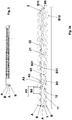
- the main parts of the new asymmetric plate exchanger comprise plates (A, B) superimposed in a pack, brazed together with possible perimeter seals, to confine the fluids inside, and holes (C) for the passage of the exchange fluids, these holes (C) are themselves brazed together at the edges or equipped with seals alternately arranged so as to convey the two fluids in question in the spaces between the plates along at least two hydraulically isolated paths (1, 2) with different head losses.
- the heat exchanger comprises at least two paths (1, 2) separated respectively for a primary fluid and a secondary fluid, each of the two paths (1, 2) being defined by a pair (A, B) of the aforementioned facing plates.
- the heat exchanger includes two different types of plates, arranged alternately in the pack making up the heat exchanger, as shown for example in Figure 3 .
- the first type of plate (A) comprises a plurality of alternating ridges (A2) and hollows (A3), arranged in a herringbone pattern, that is, arranged specularly with respect to a central plane (A4) according to two directions (X1, X2) intersecting each other.
- Said ridges (A2) and hollows (A3) have a modular or constant pitch (A5) and have a constant height or depth, that is, the distance (A6) between the top of the ridges and the bottom of the hollows is constant.
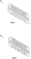
- the second type of plate (B) comprises a plurality of alternated ridges (B2) and hollows (B3), arranged in a herringbone pattern, that is, arranged specularly with respect to a central plane (B4) according to two directions (X1, X2) intersecting each other.
- Said ridges (B2) and hollows (B3) have a modular or constant pitch (B5), equal to or different from the pitch (A5) of the first type of plate (A).
- all the hollows (B3) of the plate (B) have a constant depth (B6), with the exception of localized raised portions (B31), that is, having a length much shorter than the length of the hollows (B3).
- These raised portions (B31) or lowered portions (B21) are distributed along each hollow (B3) or ridge (B2), for example, one or more for each hollow (B3) or ridge (B2), at a modular or constant distance.
- Each of these paths (1, 2) of the two fluids is created by placing one plate of the first type (A) with one plate of the second type (B), so that the hollows (A3, B3) and ridges (A2, B2) of the two plates are crossed.
- the path in which the primary fluid circulates, or the primary path (1) is obtained by placing a plate of the first type (A) with a plate of the second type (B) on the side of the lowered portions (B21) of the ridges (B2).
- This primary path (1) has a lower head loss and is formed by two series of channels (11, 12).
- the first series of channels, or the main channels (11) are formed by the hollows (B3, A3) of the two plates (B, A) facing each other, while the second series of channels, or ancillary channels (12) are transverse to the main channels (11) and created by the lowered portions (B21) that put the main channels (11) in communication transversely.
- the raised portions (B31) and corresponding lowered portions (B21) are distributed preferably aligned along directions (Y1, Y2) intersecting the direction of the ridges (B2) and hollows (B3).
- the lowered portions (B21) are aligned in a direction (Y1, Y2) parallel to the direction (X1, X2) of the hollows (B3) of the opposite specular half, and in particular are aligned with the extension of the lowered portion (B3) of the opposite specular half, thereby creating a network of main (11) and crossed secondary (12) channels.
- This path in which the secondary fluid circulates, or the secondary path (2) is obtained by placing the plate of the first type (A) with the plate of the second type (B) on the side of the raised portions (B31) of the hollows (B3).
- This secondary path (2) has a greater head loss and is formed by a series of channels (21) formed by the hollows (B3, A3) of the two facing plates (B, A), where in the main channels (21) of the secondary path (2) there are narrowed portions (22) created by the raised portions (B31), which reduce the section for the passage of the fluid, increasing the turbulence of the fluid and increasing the head loss.
Claims (10)
- Échangeur asymétrique à plaques comprenant plusieurs plaques empilées (A, B) formant un paquet, soudées et dotées de trous (C) pour le passage d'au moins deux fluides, un fluide primaire et un fluide secondaire, lesdits trous (C) étant aptes à transporter lesdits deux fluides dans les espaces entre des couples (A, B) de plaques opposées suivant au moins deux parcours hydrauliquement isolés (1, 2), chacune desdites plaques (A, B) étant dotée de crêtes (A2, B2) et de cavités (A3, B3) alternées et où lesdits deux parcours (1, 2) présentent une résistance à l'écoulement différente en présence du même débit, caractérisé en ce qu'il comprend deux types de plaques empilées alternées (A, B), où :• le premier type de plaque (A) comprend une pluralité desdites crêtes (A2) et desdites cavités (A3) alternées ayant une hauteur ou une profondeur constante (A6),• le deuxième type de plaque (B) comprend une pluralité desdites crêtes (B2) et desdites cavités (B3) alternées, où lesdites cavités (B3) sur un côté (B12) de ladite plaque (B) ont toutes une profondeur constante (B6), à l'exception d'une ou plusieurs portions en relief localisées (B31) qui sont plus courtes que la cavité (B3), et où lesdites portions en relief (B31) localisées sur ledit côté (B12) correspondent, sur le côté opposé (B11) de la même plaque (B), à des portions abaissées (B21) localisées sur les crêtes (B2).
- Échangeur asymétrique à plaques selon la revendication 1, caractérisé en ce que les portions en relief prévues peuvent être positionnées aussi bien sur les cavités que sur les crêtes, avec un effet opposé sur le côté opposé de la même plaque.
- Échangeur asymétrique à plaques selon la revendication 1 ou 2, caractérisé en ce qu'une ou plusieurs desdites portions en relief (B31) ou desdites portions abaissées (B21) sont distribuées le long de chaque cavité (B3) ou crête (B2) à une distance modulaire ou constante.
- Échangeur asymétrique à plaques selon la revendication 1, caractérisé en ce que lesdites crêtes (A2) et lesdites cavités (A3) de ladite plaque (A) du premier type sont positionnées à un pas (A5) modulaire ou constant.
- Échangeur asymétrique à plaques selon la revendication 3, caractérisé en ce que lesdites crêtes (B2) et lesdites cavités (B3) de ladite plaque (B) du deuxième type sont positionnées à un pas (B5) modulaire ou constant, égal ou différent dudit pas (A5) présent dans de la plaque (A) du premier type.
- Échangeur asymétrique à plaques selon la revendication 1, caractérisé en ce que lesdites crêtes (A2, B2) et lesdites cavités (A3, B3) sur lesdites plaques (A, B) du premier e du deuxième type sont disposées selon un motif à arête de poisson, c'est-à-dire disposées de manière spéculaire par rapport à un plan central (A4, B4) selon deux directions (X1, X2) s'entrecoupant mutuellement.
- Échangeur asymétrique à plaques selon les revendications précédentes, caractérisé en ce que le parcours primaire (1) avec une résistance à l'écoulement inférieure, dans lequel ledit fluide primaire circule, obtenu dans ladite plaque (A) du premier type, tournée vers ladite plaque (B) du deuxième type sur le côté desdites portions abaissées (B21) sur les crêtes (B2), se compose de deux séries de canaux, dont une première série de canaux principaux (11) définis par lesdites cavités (A3, B3) dans les deux plaques (A, B) opposées, et une deuxième série de canaux auxiliaires (12), disposés transversalement auxdits canaux principaux (11), définis par lesdites portions abaissées (B21) qui mettent en communication lesdits canaux principaux (11) transversalement.
- Échangeur asymétrique à plaques selon la revendication 6, caractérisé en ce que lesdites portions en relief (B31) sur la plaque (B) du deuxième type sont distribuées de manière à être alignées le long des directions (Y1, Y2) qui entrecoupent la direction (X1, X2) desdites crêtes (B2) et desdites cavités (B3).
- Échangeur asymétrique à plaques selon la revendication 7, caractérisé en ce que, sur chacune des deux moitiés spéculaires de la plaque (B) du deuxième type, lesdites portions abaissées (B21) sont alignées selon une direction (Y1, Y2) parallèle à et/ou coïncidant avec l'extension de la cavité (B3) dans la moitié spéculaire opposée, définissant de cette manière un réseau desdits canaux croisés principaux (11) et secondaires (12).
- Échangeur asymétrique à plaques selon les revendications précédentes, caractérisé en ce que le parcours secondaire (2) avec une résistance à l'écoulement supérieure, dans lequel ledit fluide secondaire circule, obtenu dans ladite plaque (A) du premier type, tournée vers ladite plaque (B) du deuxième type sur le côté desdites portions en relief (B31) sur les cavités (B3), se compose d'une série de canaux principaux (21), définis par lesdites cavités (A3, B3) dans les deux plaques opposées (A, B), où dans lesdits canaux principaux (21) du parcours secondaire (2) se trouvent des portions rétrécies (22) définies par lesdites portions en relief (B31).
Priority Applications (2)
| Application Number | Priority Date | Filing Date | Title |
|---|---|---|---|
| PL14747721T PL3017261T3 (pl) | 2013-07-03 | 2014-07-03 | Wymiennik asymetryczny z kanałami pomocniczymi do łączenia kolan rurowych |
| SI201431155T SI3017261T1 (sl) | 2013-07-03 | 2014-07-03 | Asimetrični izmenjevalnik s pomožnimi kanali za povezovalne obrate |
Applications Claiming Priority (2)
| Application Number | Priority Date | Filing Date | Title |
|---|---|---|---|
| IT000187A ITPD20130187A1 (it) | 2013-07-03 | 2013-07-03 | Scambiatore asimmetrico con canali ausiliari di collegamento fra spire |
| PCT/IB2014/062817 WO2015001506A1 (fr) | 2013-07-03 | 2014-07-03 | Echangeur asymétrique comportant des canaux auxiliaires pour relier des courbures |
Publications (2)
| Publication Number | Publication Date |
|---|---|
| EP3017261A1 EP3017261A1 (fr) | 2016-05-11 |
| EP3017261B1 true EP3017261B1 (fr) | 2019-01-02 |
Family
ID=49035790
Family Applications (1)
| Application Number | Title | Priority Date | Filing Date |
|---|---|---|---|
| EP14747721.0A Active EP3017261B1 (fr) | 2013-07-03 | 2014-07-03 | Echangeur asymétrique comportant des canaux auxiliaires pour relier des courbures |
Country Status (6)
| Country | Link |
|---|---|
| EP (1) | EP3017261B1 (fr) |
| IT (1) | ITPD20130187A1 (fr) |
| PL (1) | PL3017261T3 (fr) |
| SI (1) | SI3017261T1 (fr) |
| TR (1) | TR201904569T4 (fr) |
| WO (1) | WO2015001506A1 (fr) |
Cited By (1)
| Publication number | Priority date | Publication date | Assignee | Title |
|---|---|---|---|---|
| WO2023247160A1 (fr) * | 2022-06-22 | 2023-12-28 | Alfa Laval Corporate Ab | Échangeur de chaleur à plaques |
Families Citing this family (6)
| Publication number | Priority date | Publication date | Assignee | Title |
|---|---|---|---|---|
| DE102018002201B4 (de) | 2018-03-19 | 2021-03-18 | EAW Energieanlagenbau GmbH Westenfeld | Wasser-Lithiumbromid-Absorptionskälteanlage |
| CN108645268A (zh) * | 2018-04-30 | 2018-10-12 | 南京理工大学 | 加半圆柱凸起的板式换热器板片 |
| CN108645267A (zh) * | 2018-04-30 | 2018-10-12 | 南京理工大学 | 新型鱼骨形加梭形凸起的板式换热器板片 |
| CN108801035A (zh) * | 2018-04-30 | 2018-11-13 | 南京理工大学 | 新型鱼骨形加半圆柱状凸起的板式换热器板片 |
| CN108827058A (zh) * | 2018-04-30 | 2018-11-16 | 南京理工大学 | 一种加梭形凸起的板式换热器板片 |
| SE545690C2 (en) * | 2020-01-30 | 2023-12-05 | Swep Int Ab | A brazed plate heat exchanger and use thereof |
Family Cites Families (3)
| Publication number | Priority date | Publication date | Assignee | Title |
|---|---|---|---|---|
| AT406301B (de) * | 1998-06-24 | 2000-04-25 | Ernst P Fischer Maschinen Und | Plattenwärmetauscher |
| EP2233873A1 (fr) * | 2009-03-12 | 2010-09-29 | Robert Bosch GmbH | Échangeur thermique à plaques |
| EP2267391B1 (fr) * | 2009-06-26 | 2018-04-11 | SWEP International AB | Échangeur thermique asymétrique |
-
2013
- 2013-07-03 IT IT000187A patent/ITPD20130187A1/it unknown
-
2014
- 2014-07-03 TR TR2019/04569T patent/TR201904569T4/tr unknown
- 2014-07-03 EP EP14747721.0A patent/EP3017261B1/fr active Active
- 2014-07-03 WO PCT/IB2014/062817 patent/WO2015001506A1/fr active Application Filing
- 2014-07-03 PL PL14747721T patent/PL3017261T3/pl unknown
- 2014-07-03 SI SI201431155T patent/SI3017261T1/sl unknown
Non-Patent Citations (1)
| Title |
|---|
| None * |
Cited By (1)
| Publication number | Priority date | Publication date | Assignee | Title |
|---|---|---|---|---|
| WO2023247160A1 (fr) * | 2022-06-22 | 2023-12-28 | Alfa Laval Corporate Ab | Échangeur de chaleur à plaques |
Also Published As
| Publication number | Publication date |
|---|---|
| WO2015001506A1 (fr) | 2015-01-08 |
| ITPD20130187A1 (it) | 2015-01-04 |
| PL3017261T3 (pl) | 2019-08-30 |
| SI3017261T1 (sl) | 2019-07-31 |
| EP3017261A1 (fr) | 2016-05-11 |
| TR201904569T4 (tr) | 2019-04-22 |
Similar Documents
| Publication | Publication Date | Title |
|---|---|---|
| EP3017261B1 (fr) | Echangeur asymétrique comportant des canaux auxiliaires pour relier des courbures | |
| EP1630510B2 (fr) | Echangeur de chaleur à plaques | |
| EP2455695B1 (fr) | Échangeur de chaleur | |
| DK2585783T3 (en) | Exchanger plate and plate heat exchange | |
| EP2455694A2 (fr) | Échangeur de chaleur | |
| JP6987074B2 (ja) | 伝熱プレートおよび複数のかかる伝熱プレートを備えるプレート熱交換器 | |
| US9714796B2 (en) | Plate heat exchanger and method for manufacturing of a plate heat exchanger | |
| CN110537069B (zh) | 热传递板和包括多个此类热传递板的热交换器 | |
| EP3032208B1 (fr) | Rainure de joint d'étanchéité pour un échangeur de chaleur à plaques | |
| EP2775246B1 (fr) | Échangeur de chaleur avec joint d'étanchéité, à motif d'alvéoles | |
| CN105008843B (zh) | 板式热交换器 | |
| CN110073163B (zh) | 板式热交换器 | |
| JP4874365B2 (ja) | プレート式熱交換器及びその熱交換器を用いた冷凍サイクル装置 | |
| JP4519437B2 (ja) | 接合型プレート式熱交換器 | |
| JP5933605B2 (ja) | プレート式熱交換器 | |
| JP2011117624A (ja) | プレート式熱交換器 | |
| JP6118847B2 (ja) | プレート式熱交換器 | |
| JP2023507732A (ja) | 停滞した媒体を回避するくぼみを備えた熱交換器 |
Legal Events
| Date | Code | Title | Description |
|---|---|---|---|
| PUAI | Public reference made under article 153(3) epc to a published international application that has entered the european phase |
Free format text: ORIGINAL CODE: 0009012 |
|
| 17P | Request for examination filed |
Effective date: 20151221 |
|
| AK | Designated contracting states |
Kind code of ref document: A1 Designated state(s): AL AT BE BG CH CY CZ DE DK EE ES FI FR GB GR HR HU IE IS IT LI LT LU LV MC MK MT NL NO PL PT RO RS SE SI SK SM TR |
|
| AX | Request for extension of the european patent |
Extension state: BA ME |
|
| DAX | Request for extension of the european patent (deleted) | ||
| GRAP | Despatch of communication of intention to grant a patent |
Free format text: ORIGINAL CODE: EPIDOSNIGR1 |
|
| STAA | Information on the status of an ep patent application or granted ep patent |
Free format text: STATUS: GRANT OF PATENT IS INTENDED |
|
| INTG | Intention to grant announced |
Effective date: 20181002 |
|
| GRAS | Grant fee paid |
Free format text: ORIGINAL CODE: EPIDOSNIGR3 |
|
| GRAA | (expected) grant |
Free format text: ORIGINAL CODE: 0009210 |
|
| STAA | Information on the status of an ep patent application or granted ep patent |
Free format text: STATUS: THE PATENT HAS BEEN GRANTED |
|
| AK | Designated contracting states |
Kind code of ref document: B1 Designated state(s): AL AT BE BG CH CY CZ DE DK EE ES FI FR GB GR HR HU IE IS IT LI LT LU LV MC MK MT NL NO PL PT RO RS SE SI SK SM TR |
|
| REG | Reference to a national code |
Ref country code: GB Ref legal event code: FG4D |
|
| REG | Reference to a national code |
Ref country code: CH Ref legal event code: EP Ref country code: AT Ref legal event code: REF Ref document number: 1084930 Country of ref document: AT Kind code of ref document: T Effective date: 20190115 |
|
| REG | Reference to a national code |
Ref country code: IE Ref legal event code: FG4D |
|
| REG | Reference to a national code |
Ref country code: DE Ref legal event code: R096 Ref document number: 602014039131 Country of ref document: DE |
|
| REG | Reference to a national code |
Ref country code: SE Ref legal event code: TRGR |
|
| REG | Reference to a national code |
Ref country code: NL Ref legal event code: MP Effective date: 20190102 |
|
| REG | Reference to a national code |
Ref country code: LT Ref legal event code: MG4D |
|
| REG | Reference to a national code |
Ref country code: AT Ref legal event code: MK05 Ref document number: 1084930 Country of ref document: AT Kind code of ref document: T Effective date: 20190102 |
|
| PG25 | Lapsed in a contracting state [announced via postgrant information from national office to epo] |
Ref country code: NL Free format text: LAPSE BECAUSE OF FAILURE TO SUBMIT A TRANSLATION OF THE DESCRIPTION OR TO PAY THE FEE WITHIN THE PRESCRIBED TIME-LIMIT Effective date: 20190102 |
|
| PG25 | Lapsed in a contracting state [announced via postgrant information from national office to epo] |
Ref country code: PT Free format text: LAPSE BECAUSE OF FAILURE TO SUBMIT A TRANSLATION OF THE DESCRIPTION OR TO PAY THE FEE WITHIN THE PRESCRIBED TIME-LIMIT Effective date: 20190502 Ref country code: FI Free format text: LAPSE BECAUSE OF FAILURE TO SUBMIT A TRANSLATION OF THE DESCRIPTION OR TO PAY THE FEE WITHIN THE PRESCRIBED TIME-LIMIT Effective date: 20190102 Ref country code: LT Free format text: LAPSE BECAUSE OF FAILURE TO SUBMIT A TRANSLATION OF THE DESCRIPTION OR TO PAY THE FEE WITHIN THE PRESCRIBED TIME-LIMIT Effective date: 20190102 Ref country code: NO Free format text: LAPSE BECAUSE OF FAILURE TO SUBMIT A TRANSLATION OF THE DESCRIPTION OR TO PAY THE FEE WITHIN THE PRESCRIBED TIME-LIMIT Effective date: 20190402 Ref country code: ES Free format text: LAPSE BECAUSE OF FAILURE TO SUBMIT A TRANSLATION OF THE DESCRIPTION OR TO PAY THE FEE WITHIN THE PRESCRIBED TIME-LIMIT Effective date: 20190102 |
|
| PG25 | Lapsed in a contracting state [announced via postgrant information from national office to epo] |
Ref country code: RS Free format text: LAPSE BECAUSE OF FAILURE TO SUBMIT A TRANSLATION OF THE DESCRIPTION OR TO PAY THE FEE WITHIN THE PRESCRIBED TIME-LIMIT Effective date: 20190102 Ref country code: LV Free format text: LAPSE BECAUSE OF FAILURE TO SUBMIT A TRANSLATION OF THE DESCRIPTION OR TO PAY THE FEE WITHIN THE PRESCRIBED TIME-LIMIT Effective date: 20190102 Ref country code: IS Free format text: LAPSE BECAUSE OF FAILURE TO SUBMIT A TRANSLATION OF THE DESCRIPTION OR TO PAY THE FEE WITHIN THE PRESCRIBED TIME-LIMIT Effective date: 20190502 Ref country code: HR Free format text: LAPSE BECAUSE OF FAILURE TO SUBMIT A TRANSLATION OF THE DESCRIPTION OR TO PAY THE FEE WITHIN THE PRESCRIBED TIME-LIMIT Effective date: 20190102 Ref country code: GR Free format text: LAPSE BECAUSE OF FAILURE TO SUBMIT A TRANSLATION OF THE DESCRIPTION OR TO PAY THE FEE WITHIN THE PRESCRIBED TIME-LIMIT Effective date: 20190403 Ref country code: BG Free format text: LAPSE BECAUSE OF FAILURE TO SUBMIT A TRANSLATION OF THE DESCRIPTION OR TO PAY THE FEE WITHIN THE PRESCRIBED TIME-LIMIT Effective date: 20190402 |
|
| REG | Reference to a national code |
Ref country code: DE Ref legal event code: R097 Ref document number: 602014039131 Country of ref document: DE |
|
| PG25 | Lapsed in a contracting state [announced via postgrant information from national office to epo] |
Ref country code: EE Free format text: LAPSE BECAUSE OF FAILURE TO SUBMIT A TRANSLATION OF THE DESCRIPTION OR TO PAY THE FEE WITHIN THE PRESCRIBED TIME-LIMIT Effective date: 20190102 Ref country code: AT Free format text: LAPSE BECAUSE OF FAILURE TO SUBMIT A TRANSLATION OF THE DESCRIPTION OR TO PAY THE FEE WITHIN THE PRESCRIBED TIME-LIMIT Effective date: 20190102 Ref country code: RO Free format text: LAPSE BECAUSE OF FAILURE TO SUBMIT A TRANSLATION OF THE DESCRIPTION OR TO PAY THE FEE WITHIN THE PRESCRIBED TIME-LIMIT Effective date: 20190102 Ref country code: DK Free format text: LAPSE BECAUSE OF FAILURE TO SUBMIT A TRANSLATION OF THE DESCRIPTION OR TO PAY THE FEE WITHIN THE PRESCRIBED TIME-LIMIT Effective date: 20190102 Ref country code: SK Free format text: LAPSE BECAUSE OF FAILURE TO SUBMIT A TRANSLATION OF THE DESCRIPTION OR TO PAY THE FEE WITHIN THE PRESCRIBED TIME-LIMIT Effective date: 20190102 Ref country code: AL Free format text: LAPSE BECAUSE OF FAILURE TO SUBMIT A TRANSLATION OF THE DESCRIPTION OR TO PAY THE FEE WITHIN THE PRESCRIBED TIME-LIMIT Effective date: 20190102 |
|
| PLBE | No opposition filed within time limit |
Free format text: ORIGINAL CODE: 0009261 |
|
| STAA | Information on the status of an ep patent application or granted ep patent |
Free format text: STATUS: NO OPPOSITION FILED WITHIN TIME LIMIT |
|
| PG25 | Lapsed in a contracting state [announced via postgrant information from national office to epo] |
Ref country code: SM Free format text: LAPSE BECAUSE OF FAILURE TO SUBMIT A TRANSLATION OF THE DESCRIPTION OR TO PAY THE FEE WITHIN THE PRESCRIBED TIME-LIMIT Effective date: 20190102 |
|
| 26N | No opposition filed |
Effective date: 20191003 |
|
| PG25 | Lapsed in a contracting state [announced via postgrant information from national office to epo] |
Ref country code: MC Free format text: LAPSE BECAUSE OF FAILURE TO SUBMIT A TRANSLATION OF THE DESCRIPTION OR TO PAY THE FEE WITHIN THE PRESCRIBED TIME-LIMIT Effective date: 20190102 |
|
| REG | Reference to a national code |
Ref country code: CH Ref legal event code: PL |
|
| REG | Reference to a national code |
Ref country code: BE Ref legal event code: MM Effective date: 20190731 |
|
| PG25 | Lapsed in a contracting state [announced via postgrant information from national office to epo] |
Ref country code: LU Free format text: LAPSE BECAUSE OF NON-PAYMENT OF DUE FEES Effective date: 20190703 Ref country code: BE Free format text: LAPSE BECAUSE OF NON-PAYMENT OF DUE FEES Effective date: 20190731 Ref country code: LI Free format text: LAPSE BECAUSE OF NON-PAYMENT OF DUE FEES Effective date: 20190731 Ref country code: CH Free format text: LAPSE BECAUSE OF NON-PAYMENT OF DUE FEES Effective date: 20190731 |
|
| PG25 | Lapsed in a contracting state [announced via postgrant information from national office to epo] |
Ref country code: IE Free format text: LAPSE BECAUSE OF NON-PAYMENT OF DUE FEES Effective date: 20190703 |
|
| PG25 | Lapsed in a contracting state [announced via postgrant information from national office to epo] |
Ref country code: CY Free format text: LAPSE BECAUSE OF FAILURE TO SUBMIT A TRANSLATION OF THE DESCRIPTION OR TO PAY THE FEE WITHIN THE PRESCRIBED TIME-LIMIT Effective date: 20190102 |
|
| PG25 | Lapsed in a contracting state [announced via postgrant information from national office to epo] |
Ref country code: HU Free format text: LAPSE BECAUSE OF FAILURE TO SUBMIT A TRANSLATION OF THE DESCRIPTION OR TO PAY THE FEE WITHIN THE PRESCRIBED TIME-LIMIT; INVALID AB INITIO Effective date: 20140703 Ref country code: MT Free format text: LAPSE BECAUSE OF FAILURE TO SUBMIT A TRANSLATION OF THE DESCRIPTION OR TO PAY THE FEE WITHIN THE PRESCRIBED TIME-LIMIT Effective date: 20190102 |
|
| PG25 | Lapsed in a contracting state [announced via postgrant information from national office to epo] |
Ref country code: MK Free format text: LAPSE BECAUSE OF FAILURE TO SUBMIT A TRANSLATION OF THE DESCRIPTION OR TO PAY THE FEE WITHIN THE PRESCRIBED TIME-LIMIT Effective date: 20190102 |
|
| PGFP | Annual fee paid to national office [announced via postgrant information from national office to epo] |
Ref country code: CZ Payment date: 20230622 Year of fee payment: 10 |
|
| PGFP | Annual fee paid to national office [announced via postgrant information from national office to epo] |
Ref country code: TR Payment date: 20230627 Year of fee payment: 10 Ref country code: PL Payment date: 20230621 Year of fee payment: 10 |
|
| PGFP | Annual fee paid to national office [announced via postgrant information from national office to epo] |
Ref country code: IT Payment date: 20230627 Year of fee payment: 10 Ref country code: GB Payment date: 20230727 Year of fee payment: 10 |
|
| PGFP | Annual fee paid to national office [announced via postgrant information from national office to epo] |
Ref country code: SI Payment date: 20230621 Year of fee payment: 10 Ref country code: SE Payment date: 20230727 Year of fee payment: 10 Ref country code: FR Payment date: 20230725 Year of fee payment: 10 Ref country code: DE Payment date: 20230727 Year of fee payment: 10 |