EP3032208B1 - Rainure de joint d'étanchéité pour un échangeur de chaleur à plaques - Google Patents
Rainure de joint d'étanchéité pour un échangeur de chaleur à plaques Download PDFInfo
- Publication number
- EP3032208B1 EP3032208B1 EP15184715.9A EP15184715A EP3032208B1 EP 3032208 B1 EP3032208 B1 EP 3032208B1 EP 15184715 A EP15184715 A EP 15184715A EP 3032208 B1 EP3032208 B1 EP 3032208B1
- Authority
- EP
- European Patent Office
- Prior art keywords
- dimples
- heat exchanger
- gasket
- wavy
- plate
- Prior art date
- Legal status (The legal status is an assumption and is not a legal conclusion. Google has not performed a legal analysis and makes no representation as to the accuracy of the status listed.)
- Active
Links
- 230000001788 irregular Effects 0.000 claims description 3
- 239000012530 fluid Substances 0.000 description 14
- 239000000463 material Substances 0.000 description 5
- 238000007789 sealing Methods 0.000 description 4
- 210000000988 bone and bone Anatomy 0.000 description 3
- 239000004033 plastic Substances 0.000 description 3
- 230000007704 transition Effects 0.000 description 3
- XLYOFNOQVPJJNP-UHFFFAOYSA-N water Substances O XLYOFNOQVPJJNP-UHFFFAOYSA-N 0.000 description 3
- 241000251468 Actinopterygii Species 0.000 description 2
- 235000019688 fish Nutrition 0.000 description 2
- 238000010438 heat treatment Methods 0.000 description 2
- 238000000465 moulding Methods 0.000 description 2
- 229910001220 stainless steel Inorganic materials 0.000 description 2
- 239000010935 stainless steel Substances 0.000 description 2
- 229910001369 Brass Inorganic materials 0.000 description 1
- 241000252203 Clupea harengus Species 0.000 description 1
- 241000197200 Gallinago media Species 0.000 description 1
- HCHKCACWOHOZIP-UHFFFAOYSA-N Zinc Chemical compound [Zn] HCHKCACWOHOZIP-UHFFFAOYSA-N 0.000 description 1
- 229910052782 aluminium Inorganic materials 0.000 description 1
- XAGFODPZIPBFFR-UHFFFAOYSA-N aluminium Chemical compound [Al] XAGFODPZIPBFFR-UHFFFAOYSA-N 0.000 description 1
- 238000005452 bending Methods 0.000 description 1
- 239000010951 brass Substances 0.000 description 1
- 238000005219 brazing Methods 0.000 description 1
- -1 cobber Substances 0.000 description 1
- 230000006835 compression Effects 0.000 description 1
- 238000007906 compression Methods 0.000 description 1
- 238000010276 construction Methods 0.000 description 1
- 238000007667 floating Methods 0.000 description 1
- 235000019514 herring Nutrition 0.000 description 1
- 229910052751 metal Inorganic materials 0.000 description 1
- 239000002184 metal Substances 0.000 description 1
- 238000012986 modification Methods 0.000 description 1
- 230000004048 modification Effects 0.000 description 1
- 238000012856 packing Methods 0.000 description 1
- 238000002360 preparation method Methods 0.000 description 1
- 238000004321 preservation Methods 0.000 description 1
- 239000002994 raw material Substances 0.000 description 1
- 238000007493 shaping process Methods 0.000 description 1
- 239000007787 solid Substances 0.000 description 1
- 239000011701 zinc Substances 0.000 description 1
- 229910052725 zinc Inorganic materials 0.000 description 1
Images


Classifications
-
- F—MECHANICAL ENGINEERING; LIGHTING; HEATING; WEAPONS; BLASTING
- F28—HEAT EXCHANGE IN GENERAL
- F28F—DETAILS OF HEAT-EXCHANGE AND HEAT-TRANSFER APPARATUS, OF GENERAL APPLICATION
- F28F3/00—Plate-like or laminated elements; Assemblies of plate-like or laminated elements
- F28F3/08—Elements constructed for building-up into stacks, e.g. capable of being taken apart for cleaning
- F28F3/10—Arrangements for sealing the margins
-
- F—MECHANICAL ENGINEERING; LIGHTING; HEATING; WEAPONS; BLASTING
- F28—HEAT EXCHANGE IN GENERAL
- F28D—HEAT-EXCHANGE APPARATUS, NOT PROVIDED FOR IN ANOTHER SUBCLASS, IN WHICH THE HEAT-EXCHANGE MEDIA DO NOT COME INTO DIRECT CONTACT
- F28D9/00—Heat-exchange apparatus having stationary plate-like or laminated conduit assemblies for both heat-exchange media, the media being in contact with different sides of a conduit wall
- F28D9/0031—Heat-exchange apparatus having stationary plate-like or laminated conduit assemblies for both heat-exchange media, the media being in contact with different sides of a conduit wall the conduits for one heat-exchange medium being formed by paired plates touching each other
- F28D9/0043—Heat-exchange apparatus having stationary plate-like or laminated conduit assemblies for both heat-exchange media, the media being in contact with different sides of a conduit wall the conduits for one heat-exchange medium being formed by paired plates touching each other the plates having openings therein for circulation of at least one heat-exchange medium from one conduit to another
- F28D9/005—Heat-exchange apparatus having stationary plate-like or laminated conduit assemblies for both heat-exchange media, the media being in contact with different sides of a conduit wall the conduits for one heat-exchange medium being formed by paired plates touching each other the plates having openings therein for circulation of at least one heat-exchange medium from one conduit to another the plates having openings therein for both heat-exchange media
Definitions
- the present invention relates to a heat exchanger of the kind where a plurality of plates is stacked and where they, due to surface structures, form flow paths between neighboring plates.
- the invention relates to a gasket plate heat exchanger where the plates define gasket holding wavy sections where a gasket is located and / or squeezed between two neighbouring heat exchanger plates.
- Such a heat exchanger is known from DE-C-19540271 which discloses a heat exchanger according to the preamble of claim 1.
- a plate heat exchanger uses plates to transfer heat between two media, typically fluids flowing in separated first and second flow paths. Compared with a conventional heat exchanger, the fluids are exposed to a large surface area defined by the surfaces of the plates. This increases the exchange of thermal energy between the fluids.
- Plate heat exchangers are common for hot water boilers, and particularly for instantaneous preparation of domestic hot water or for heating circuits etc.
- the flow paths each connects to either a primary or a secondary fluid connection e.g. for supplying heating fluid or domestic hot water.
- the first and second flow paths are on opposite sides of the plates, and the plates come with a number of different structures such as fishbone or herringbone corrugations.
- fishbone heat exchanger plates When stacking fishbone heat exchanger plates, taken as an example, they are positioned such that they connect in crossing points of the corrugations and as the corrugations form relatively sharp pointed tops, the contact area between tops of adjacent plates becomes small and less well defined. In case the fluids are pressurized it results in concentrated contact forces leading to permanent deformations of the contact points.
- An alternative design is the surface structures to be defined as dimple patterns making it possible to design contact areas with well-defined areas, and thus well-defined and optimized strength and hydraulic characteristics.
- the profile height for the dimple pattern can be reduced by typically 30% compared to the traditional herring bone pattern and still maintaining the same pressure drop and heat transfer.
- the reduced profile height results in approximately twice the number of brazing points thus increasing the strength.
- thinner plates can be applied.
- the invention is related to gasket exchangers where the stack of heat exchanger plates are held together by an external force, such as when located and / or squeezed between top and bottom plates being fixed by bolts, and is based on the discovery that the essential in realizing a strong heat exchanger is not the surface area if the tops respectively bottoms of the dimples, but rather the length of their circumference.
- the heat exchanger plates may define inlets and outlets for the flow paths defined between neighboring plates, where these typically are formed as four corner openings connecting the fluid such that two openings connects a first fluid supply to an upper side of the plate by an inlet and an outlet and a second supply connecting to the two other openings on the lower side of the plate.
- Heat transferring areas then are formed in the flow paths from inlet to outlet by the surface structures. Opening areas are the areas in the circumference of the openings and usually comprises structures to support these. Further a transition zone may exist in the zone from the opening to the heat transferring areas for distributing the fluids to the full extent of the heat transferring area.
- a gasket, or packing usually are positioned close to the rim of the heat exchange plates encircling the heat transfer area to seal it from the externals preventing the fluids to leak out of the flow paths between the plates. This sealing will be necessary for the flow paths at both sides of any of the plates and thus by placing the upper and lower gasket relative to a plate at the same position they will form a support to the heat exchanger plate and thus protecting it from deformations due to the pressures of the media or the pre-pressurization of the gasket.
- Fig. 1 illustrates a plate heat exchanger 1 comprising a plurality of heat exchanger plates 2 which are stacked in a stacking direction visualized by the arrow 3.
- the heat exchanging plates are stacked with tops against bottoms.
- Fig. 2 illustrates the heat exchanger in a top view of the dimple kind surface structure, this being the design of illustration, but the present invention may also apply to other designs such as fish bone.
- the heat exchanger plate has four corner openings 4, 5, 6, 7 for connecting to the fluid connections such that two openings 5, 7 connect a first fluid supply to an upper side of the plate by an inlet and an outlet - an overall flow direction from the inlet to outlet is illustrated by the solid arrow.
- a second supply is connected to the two openings 4, 6 on the lower side of the plate.
- An overall flow direction from the inlet to the outlet is illustrated by the slashed arrow.
- the flow is counter flow.
- cross-counter flow is an option, where 5+6 and 4+7 are connected.
- parallel flow or parallel cross flow is an option.
- a dimple structure with flat dimple tops and bottoms is illustrated by the white and black oval marks 9, 10 shown as an enlargement of a section 8 of the heat transfer area of the plate, where the dimples protrude in opposite directions.
- the plates could e.g. be made from a planar plate which is deformed by stamping to form the dimples extending in opposite directions relative to the central plane of the original planar plate.
- Fig. 3 shows four plates 14, 15, 16, 17 where each plate forms a first set of dimples 12 having flat top areas 9 and a second set of dimples 13 having flat bottom areas 10.
- the first and second sets of dimples extend from a fictive central plane 11 (illustrated for plate 15) in opposite directions away from the central plane.
- the plates and thus the dimples can be manufactured by pressing a thin plate of metal, e.g. stainless steel, aluminum, cobber, brass or zinc or plastic into the desired shape, e.g. in a die.
- the plates can also be made by molding, e.g. by pressure molding of plastic in a mold or die.
- the figure illustrates a side view and the dimples could have top surfaces of any shape, e.g. an elliptical shaped design of dimples according to the embodiment of illustration of the present invention.
- Other shapes may apply, e.g. super-elliptically, rectangular etc. as long as they have a well-defined extension in a first direction and a well-defined extension in a second direction being orthogonal to the first direction.
- dimple tops 12 are placed against dimple bottoms 13 of an upper neighboring plate and in the same manner that dimple bottoms 13 are connected to dimple tops 12 of the lower neighboring plate.
- Fig. 3 also illustrates that the side walls of the dimples are roughly 45 degrees, c.f. the angle indication.
- the top and bottom dimples are as close as possible to each other. This leads to a higher number of dimples and to a higher strength.
- the angle of 45 degrees is limited by e.g. the maximum elongation of the stainless steel material. For practical reasons, e.g. due to tolerances of the pressing tools, a smaller angle is often applied.
- the walls are smoothly formed by free floating of the material without sharp edges and without flat or plane plate sections except from those appearing at the dimple tops and dimple bottoms, i.e. where one plate meet an adjacent plate.
- any such additional flat section would have created weak sections and could have allowed a pressure difference between fluids in the first and second paths to deform the plates - potentially, plates could bulge and crack at the edges. There is no pressure gradient over the connected tops and bottoms as the same fluids flow with the same pressures at the opposing sides of the connections.
- the structure illustrated in Fig. 3 enables a reduced plate thickness. Due to the absence of edges and flat sections between dimple tops and bottoms the pressures are directed into the dimple walls in a manner where they are absorbed essentially without plastic deformation. Further, all the connections have enlarged contact areas relative to the fishbone structures and the pressure-forces are therefore distributed over a larger area.
- the dimples of the first set of dimples form a first contact face arranged against contact faces of an adjacent plate, and such that the dimples of the second set of dimples form a second contact face arranged against a contact face of an adjacent plate.
- Fig. 4 is a further top view of a general heat exchanger plate illustrating a gasket part 30 positioned close to the rim of the plate sealing the heat transfer area 31 from the externals.
- the gasket 32 traditionally are positioned in a gasket groove, or well, where the cross sections of groove and gasket often are shaped alike and the gasket groove usually has essentially flat bottoms, that if unsupported at the opposite side of the heat exchanger plate may risk to deform under e.g. media pressure or pre-pressurized gaskets by especially thin plates.
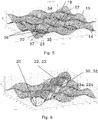
- Fig. 5 illustrates one solution according to the present invention, where a heat exchanger plate 15 comprising at a first wavy section 34 aligned with a second wavy 35 section of a neighbouring plate 16 thus defing a gasket section 37 between them, where the wavy sections 34, 35 in the illustration of Fig. 5 is the area between the lines 36.
- the gasket section 37 is where a gasket 30, 32 is to be be positioned between the two plates 15, 16 and thus extends in a length direction being longer than its transverse direction, where the length direction may form a straight linear tajectory, such as illustrated in e.g. Figs.8-10 or a curvatured trajectory such as illustrated e.g. in Figs. 13 and 14 .
- the transverse length may be constant or may be changing, such as illustrated e.g. in Fig. 7 , or it may itself be wavy, regular or irregular.
- the waves of the wavy sections 34, 35 may be waves in the plate 15, 16 surfaces and are in a first embodiment of the present invention such that the surface waves seen in the length direction, either with regular or irregular waves.
- the waves in the wavy sections 34, 35 extend with waves in the transverse direction, such that the waves may be either, or such that surface of the plates waves in both the length and transverse directions of the wavy sections 34, 35, where one way to form this is by shaping the wavy sections 34, 35 with first sets of dimples 22 corresponding to dimple tops of the upper plate 15 having flat first surface areas 19 and dimple bottoms 23 of the neighboring lower plate 16 having flat second surface areas 20, and where the wall sections from the edges of the dimples 22, 23 comprises no edges or corners but may be curved or straightnor does it comprise any flat unsuported surface areas parallel to the imagiary plane 11. That the flat surface areas19, 20 are supported in the present context means they forms contact area to a flat surface opposite to the respective neighboring plate 16, 15. Unsupported in the same manner means it is not in contact with any such feature.
- unsupportet flat surfaces 19, 20 refer to planes essential parallel to the fictive plane 11, the waves may comprise unsupported turning tops and bottoms of the wavy structures.
- the waves are formed by dimples 22, 23where the flat first surface areas 19 within the first wavy section 34 forms a first contact face arranged against a contact face of a plane surface being upper to the plate 15, such as second surface areas 20 of dimple bottoms 23 of an upper plate.
- the flat second surface areas 20 within the second wavy section 35 forms a second contact face arranged against a contact face of a plane surface being lower to the plate 16,such as first surface areas 19 of dimple tops 22 of a lower plate.
- Fig.6 illustrate the same first wavy section 34 of the lower plate for the gasket section 37 Fig. 5 with a gasket 30, 32.
- the uncompressed gasket height usually is larger than the maximum height within the gasket section 37 from a first surface area to a second surface area such as at least 110%, this usually being the doubble of the distance form a first flat surface area 19 to a second flat surface area 20 of a plate 15.
- the gasket 32 may have flat top and bottom suraces or may have a wavy topology reflecting the surface structures of the wavy first and second sections 34, 35 but with an factor of e.g. 1,1 larger that the height between the wawy sections 34, 35. When the plates are mounted in the frame, the gasket will be deformed.
- each of the plates 15, 16 further may comprise respectively dimples 23a, 22a, reaching in the direction towards the gasket 30, 32 forming contact faces against the other of the respective of the two neighboring plates15, 16, in the same manner as illustrated in e.g. Fig. 3 where first set dimples 22 of lower plate 15 forms contact faces agains second set dimples 23 of the upper plate 16. Since these will be positioned outside but at the edges of the wavy sections 34, 35 they forms edge dimples to the gasket section 37 helping both to strengthen it but also to confine and fix the gasket 30, 32 within the gasket section 37.
- the gaskets experience wavy 'sides' just as they lean against sloping sides. All of this assists in keeping the gasket firmly in position,
- the dimples 22, 23 may in one embodiment be special to the wavy sections 34, 35 different from the surface structures such as in the heat transfer area 31, either differently designed dimples or a quite different design such as fish bone.
- the whole of, or at least a section of the heat transfer area 31, and / or the opening area 33 and / or an optional transition zone therebetween comprises dimples 22, 23, the gasket simply being positioned in sections between the dimples.
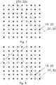
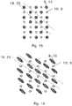
- Figs. 7-18 illustrates a number of different embodiments of the present invention where all the figures illustrate a top view of a plate 15, 16 the white shapes 22 representing eiher a first or a second set of dimples and the black shapes correspondingly representing the other of either the first or second kind of dimples 23.
- Fig. 7 thus illustrates a top view of a further embodiement of the present invention where the gasket is shaped to reach out of the openings formed between connected edge dimples 22a, 23a.
- This gasket design has the advangage of being more stable and to give an easier fixation during mounting.
- Fig. 8 illustrates a top view of an embodiment where the gasket may comprise branches extending in different directions.
- Fig. 9 illustrates a top view of an embodiment where the gasket may bend in different directions.
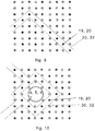
- Fig. 10 is an embodiment where the gasket changes direction and fig. 10 is an embodiment combining the embodiments of fig. 8 and 9 and further forming a sealed enclosure encircling e.g. a opening 4, 5, 6, 7.
- Fig. 11 illustrates a further embodiment where the wavy sections 34, 35 not only comprises dimples 22, 23 extending opposite to the gasket, but also a set of opposite directed dimples 22b, 23b extending towards the gasket just as the dimples at the sides of the wavy sections 34, 35, thus reaching through the gasket section 37 forming contact faces to the dimples of the other plate within the gasket section 37.
- the gasket 30, 32 in this gasket section 37 then will be shaped to allow the flat surface areas 19, 20 of the dimples 22b, 23b to contact, such as comprising openings 38 through the gasket 30, 32, or being essentially S-shaped making a slalom kind of trajectory around the the dimples 22b, 23b being in contact within the gasket section
- Fig. 12 illustrates an embodiment combining the featuers of figs. 8 and 11 .
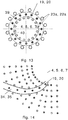
- Fig. 13 illustrate an embodiment with cicular arranged wavy sections 34, 35 possible encircling an opening 4, 5, 6, 7, and in the illustrated embodiment having larger edge dimples 22a, 23a at the outside edge 39 than at the inner edge 40, though the opposite may also be the situation, or the outer and inner edge dimples being of the same size.
- the inner and outer edge dimples has different forms such as curvature of the walls or shape of the top and bottom surface areas.
- edge dimples 22a, 23 at the one side of the wavy sections 34, 35 may be differently shaped or differently sized relative to the edge dimples 22a, 23a at the other side.
- Fig. 14 illustrate an alternative embodiment with curved wavy sections 34, 35 spiralling away from a center section such as but not limited to an opening 4, 5, 6, 7, but any other curvatures of the trajectory of the wavy sections 34, 35 also applies to the present invention.
- dimple tops 19, 20 are differently sized to the dimple bottoms 20, 19, the plates thus positioned with the large dimples 23, 22 being top at one plate and the small dimples 22, 23 being bottoms, but vice verca at the neighboring plates, thus that dimples of essentially the same sizes and shapes forms the flat contact surfaces.
- Fig. 16 illustrate an alternative embodiment to that of Fig. 15 , but where the opposing dimples 22, 23 are of different size and shapes, such as respectively elliptical and circular.
- Fig. 17 illustrate an alternative embodiment to that of Fig. 15 , but where the opposing dimples 22, 23 are of different size and shapes, such as respectively elliptical and rectangular.
- the dimples 22, 23 are positioned in a lattice structure where each of the dimples 22 of the first set are neighboured by four dimples 23 of the second set and vice versa.
- the dimples 22, 23 could represent any of the dimples such as those forming the surface structures in the heat transfering area, in the opening area and / or in the transition zone between the opening and the heat transfering areas.
- rows 41 of lines of sight extends in a 45 degrees angle relative lattice directions given by arrows 42 and 43.
- These lines of sight forms natural wavy sections 34, 35 according to the present invention and could therefore in one embodiment of the present invention be used as gasket section 37, such as by sealing an opening area from the heat transfering area by connecting two egde parts 30 of the gasket with a part 32 extending at a 45 degrees angle relative to the lattice directions 42, 43 sealing off an opening 4, 5, 6, 7.
- all or some of the different dimples 12, 13, 22, 23, 22a, 22b, 23a, 23b may be similar shaped and sized.
Landscapes
- Engineering & Computer Science (AREA)
- Physics & Mathematics (AREA)
- Thermal Sciences (AREA)
- Mechanical Engineering (AREA)
- General Engineering & Computer Science (AREA)
- Heat-Exchange Devices With Radiators And Conduit Assemblies (AREA)
Claims (17)
- Échangeur de chaleur comportant une pluralité de plaques empilées (14, 15, 16, 17) qui, du fait de structures de surface, forme des passages d'écoulement entre plaques voisines, au moins une plaque (15) comportant, au niveau d'une première section ondulée (34) alignée avec une deuxième section ondulée (35) d'une plaque voisine (16) dans laquelle un joint (30, 32) est positionné entre les première et deuxième sections ondulées (34, 35), définissant ainsi une section (37) de joint où les ondulations sont formées dans une direction longitudinale de la trajectoire de la section (37) de joint, caractérisé en ce que les ondulations de la première section ondulée (34) sont formées par un premier ensemble de cuvettes (22) dotées de zones (19) de premières surfaces plates, et en ce que les ondulations de la deuxième section ondulée (35) de la plaque voisine (16) sont formées par un deuxième ensemble de cuvettes (23) faisant saillie dans le sens opposé par rapport au premier ensemble de cuvettes (22) et dotées de zones (20) de deuxièmes surfaces plates, ladite zone (19) de première surface plate de chaque cuvette du premier ensemble de cuvettes (22) formant une première face de contact disposée contre une face de contact d'une zone (20) de surface plate d'une cuvette d'une plaque adjacente, et ladite zone (20) de surface plate de chaque cuvette du deuxième ensemble de cuvettes (23) formant une deuxième face de contact disposée contre une face de contact d'une zone de surface plate d'une cuvette d'une plaque adjacente.
- Échangeur de chaleur selon la revendication 1 ou 2, les ondulations étant formées dans une direction transverse à la trajectoire de la section (37) de joint.
- Échangeur de chaleur selon la revendication 4, toutes les zones plates dans lesdites première et deuxième sections ondulées étant alignées avec des plaques voisines.
- Échangeur de chaleur selon la revendication 4 ou 5, les première et deuxième sections ondulées formant un motif régulier d'ondulations.
- Échangeur de chaleur selon la revendication 4 ou 5, les première et deuxième sections ondulées formant un motif changeant d'ondulations.
- Échangeur de chaleur selon la revendication 7, les première et deuxième sections ondulées formant un motif irrégulier d'ondulations.
- Échangeur de chaleur selon l'une quelconque des revendications précédentes, la hauteur du joint non comprimé étant plus grande que la hauteur d'une zone de première surface à une zone de deuxième surface.
- Échangeur de chaleur selon la revendication 9, la hauteur du joint non comprimé valant au moins 110% de la hauteur d'une zone de première surface à une zone de deuxième surface.
- Échangeur de chaleur selon l'une quelconque des revendications précédentes, le joint entre lesdites première et deuxième sections ondulées étant positionné de façon à séparer une section d'une plaque comportant une lumière du reste de la plaque comportant une zone d'échange de chaleur.
- Échangeur de chaleur selon l'une quelconque des revendications précédentes, des joints n'étant positionnés que d'un côté des sections ondulées des plaques.
- Échangeur de chaleur selon l'une quelconque des revendications 1 à 11, des joints étant positionnés des deux côtés des sections ondulées des plaques.
- Échangeur de chaleur selon l'une quelconque des revendications précédentes, les joints présentant des plates surfaces supérieure et inférieure mais étant déformés lorsqu'ils sont positionnés entre les première et deuxième sections ondulées.
- Échangeur de chaleur selon l'une quelconque des revendications précédentes, chaque plaque comportant à la fois des premier et deuxième ensembles de cuvettes dans les première et deuxième sections ondulées, le premier ensemble de cuvettes de la première section ondulée touchant le deuxième ensemble de cuvettes du deuxième ensemble de cuvettes à travers des ouvertures dans le joint.
- Échangeur de chaleur selon l'une quelconque des revendications précédentes, des cuvettes de la première section ondulée touchant des cuvettes de la deuxième section ondulée à travers des ouvertures dans le joint.
- Échangeur de chaleur selon l'une quelconque des revendications précédentes, chacune des première et deuxième sections ondulées comportant à la fois des premier et deuxième ensembles de cuvettes et le joint étant serré entre des premiers ensembles de cuvettes de la première section ondulée et des deuxièmes ensembles de cuvettes de la deuxième section ondulée et des deuxièmes ensembles de cuvettes de la première section ondulée touchant un premier ensemble de cuvettes de la deuxième section ondulée à travers des trous dans le joint.
- Échangeur de chaleur selon l'une quelconque des revendications précédentes, les structures de surface formant les passages d'écoulement dans les sections de transfert de chaleur des plaques étant également formées par deux ensembles de cuvettes faisant saille sur les côtés opposés de chaque plaque et dotées de zones de surfaces plates formant des faces de contact disposées contre des faces de contact d'une plaque adjacente.
- Échangeur de chaleur selon la revendication 16, les premier et deuxième ensembles de cuvettes des première et deuxième sections ondulées faisant partie des deux ensembles de cuvettes.
Applications Claiming Priority (1)
| Application Number | Priority Date | Filing Date | Title |
|---|---|---|---|
| DKPA201400716 | 2014-12-10 |
Publications (2)
| Publication Number | Publication Date |
|---|---|
| EP3032208A1 EP3032208A1 (fr) | 2016-06-15 |
| EP3032208B1 true EP3032208B1 (fr) | 2017-04-19 |
Family
ID=54105736
Family Applications (1)
| Application Number | Title | Priority Date | Filing Date |
|---|---|---|---|
| EP15184715.9A Active EP3032208B1 (fr) | 2014-12-10 | 2015-09-10 | Rainure de joint d'étanchéité pour un échangeur de chaleur à plaques |
Country Status (3)
| Country | Link |
|---|---|
| EP (1) | EP3032208B1 (fr) |
| CN (1) | CN105698585B (fr) |
| RU (1) | RU2626032C2 (fr) |
Families Citing this family (5)
| Publication number | Priority date | Publication date | Assignee | Title |
|---|---|---|---|---|
| JP2018523085A (ja) | 2015-08-14 | 2018-08-16 | ダンフォス アクチ−セルスカブ | 少なくとも2つの蒸発器群を有する蒸気圧縮システム |
| US10775086B2 (en) | 2015-10-20 | 2020-09-15 | Danfoss A/S | Method for controlling a vapour compression system in ejector mode for a prolonged time |
| EP3365618B1 (fr) | 2015-10-20 | 2022-10-26 | Danfoss A/S | Procédé de commande de système à compression de vapeur à valeur de réglage variable de pression de récepteur |
| CN106247829A (zh) * | 2016-08-15 | 2016-12-21 | 安徽天祥空调科技有限公司 | 一种板式换热器的制备工艺 |
| DK180146B1 (en) | 2018-10-15 | 2020-06-25 | Danfoss As Intellectual Property | Heat exchanger plate with strenghened diagonal area |
Family Cites Families (9)
| Publication number | Priority date | Publication date | Assignee | Title |
|---|---|---|---|---|
| US2281754A (en) * | 1937-01-27 | 1942-05-05 | Cherry Burreil Corp | Heat exchanger |
| GB1043224A (en) * | 1961-09-05 | 1966-09-21 | Howden James & Co Ltd | Improvements in or relating to heat exchangers |
| SU974090A1 (ru) * | 1979-03-05 | 1982-11-15 | Предприятие П/Я Р-6273 | Пластинчатый теплообменный элемент |
| GB9119727D0 (en) * | 1991-09-16 | 1991-10-30 | Apv Baker Ltd | Plate heat exchanger |
| DE19540271C1 (de) * | 1995-10-28 | 1996-11-07 | Gea Ecoflex Gmbh | Plattenwärmetauscher |
| SE528847C2 (sv) * | 2005-01-28 | 2007-02-27 | Alfa Laval Corp Ab | Packningsaggregat för plattvärmeväxlare |
| KR100581843B1 (ko) * | 2005-05-09 | 2006-05-22 | 대원열판(주) | 판형열교환기의 전열판과 가스켓의 결합구조 |
| SE532344C2 (sv) * | 2007-12-21 | 2009-12-22 | Alfa Laval Corp Ab | Packningsstöd i värmeväxlare och värmeväxlare innefattande packningsstöd |
| CN102393155A (zh) * | 2011-11-02 | 2012-03-28 | 山东大学 | 一种新型三维网垫板式换热器 |
-
2015
- 2015-09-10 EP EP15184715.9A patent/EP3032208B1/fr active Active
- 2015-11-03 CN CN201510736976.XA patent/CN105698585B/zh active Active
- 2015-12-03 RU RU2015151736A patent/RU2626032C2/ru active
Also Published As
| Publication number | Publication date |
|---|---|
| CN105698585A (zh) | 2016-06-22 |
| CN105698585B (zh) | 2018-06-22 |
| RU2626032C2 (ru) | 2017-07-21 |
| RU2015151736A (ru) | 2017-06-08 |
| EP3032208A1 (fr) | 2016-06-15 |
Similar Documents
| Publication | Publication Date | Title |
|---|---|---|
| EP3032208B1 (fr) | Rainure de joint d'étanchéité pour un échangeur de chaleur à plaques | |
| KR101445474B1 (ko) | 열교환판과 판형 열교환기 | |
| AU2008354066B2 (en) | A plate heat exchanger | |
| EP2363677B1 (fr) | Procédé de fabrication d'échangeur thermique de plaque et échangeur thermique de plaque | |
| EP3115733B1 (fr) | Plaque d'échange de chaleur pour un échangeur de chaleur du type à plaques et échangeur de chaleur du type à plaques doté de ladite plaque d'échange de chaleur | |
| EP3017261B1 (fr) | Echangeur asymétrique comportant des canaux auxiliaires pour relier des courbures | |
| EP3640577B1 (fr) | Échangeur de chaleur comprenant plaques dotée d'une zone diagonale renforcée | |
| WO2020239894A1 (fr) | Échangeur de chaleur de sécurité à deux milieux | |
| US10145625B2 (en) | Dimple pattern gasketed heat exchanger | |
| US11320207B2 (en) | Heat transfer plate for plate heat exchanger and plate heat exchanger with the same | |
| US11639829B2 (en) | Gasket and assembly for a plate heat exchanger | |
| KR101987599B1 (ko) | 용접식 판형 열교환기 | |
| US20210262734A1 (en) | Plate heat exchanger with reinforced covers and method for the production of said reinforced covers and their assembly | |
| EP3015809B1 (fr) | Échangeur thermique de plaque | |
| CN109813159B (zh) | 用于板式热交换器的传热板和具有传热板的板式热交换器 | |
| GB2527494B (en) | A heat exchanger assembly |
Legal Events
| Date | Code | Title | Description |
|---|---|---|---|
| PUAI | Public reference made under article 153(3) epc to a published international application that has entered the european phase |
Free format text: ORIGINAL CODE: 0009012 |
|
| AK | Designated contracting states |
Kind code of ref document: A1 Designated state(s): AL AT BE BG CH CY CZ DE DK EE ES FI FR GB GR HR HU IE IS IT LI LT LU LV MC MK MT NL NO PL PT RO RS SE SI SK SM TR |
|
| AX | Request for extension of the european patent |
Extension state: BA ME |
|
| 17P | Request for examination filed |
Effective date: 20161206 |
|
| RBV | Designated contracting states (corrected) |
Designated state(s): AL AT BE BG CH CY CZ DE DK EE ES FI FR GB GR HR HU IE IS IT LI LT LU LV MC MK MT NL NO PL PT RO RS SE SI SK SM TR |
|
| GRAP | Despatch of communication of intention to grant a patent |
Free format text: ORIGINAL CODE: EPIDOSNIGR1 |
|
| INTG | Intention to grant announced |
Effective date: 20170202 |
|
| GRAS | Grant fee paid |
Free format text: ORIGINAL CODE: EPIDOSNIGR3 |
|
| GRAA | (expected) grant |
Free format text: ORIGINAL CODE: 0009210 |
|
| AK | Designated contracting states |
Kind code of ref document: B1 Designated state(s): AL AT BE BG CH CY CZ DE DK EE ES FI FR GB GR HR HU IE IS IT LI LT LU LV MC MK MT NL NO PL PT RO RS SE SI SK SM TR |
|
| REG | Reference to a national code |
Ref country code: GB Ref legal event code: FG4D |
|
| REG | Reference to a national code |
Ref country code: CH Ref legal event code: EP |
|
| REG | Reference to a national code |
Ref country code: AT Ref legal event code: REF Ref document number: 886393 Country of ref document: AT Kind code of ref document: T Effective date: 20170515 |
|
| REG | Reference to a national code |
Ref country code: IE Ref legal event code: FG4D |
|
| REG | Reference to a national code |
Ref country code: DE Ref legal event code: R096 Ref document number: 602015002326 Country of ref document: DE |
|
| REG | Reference to a national code |
Ref country code: NL Ref legal event code: MP Effective date: 20170419 |
|
| REG | Reference to a national code |
Ref country code: FR Ref legal event code: PLFP Year of fee payment: 3 |
|
| REG | Reference to a national code |
Ref country code: LT Ref legal event code: MG4D |
|
| REG | Reference to a national code |
Ref country code: AT Ref legal event code: MK05 Ref document number: 886393 Country of ref document: AT Kind code of ref document: T Effective date: 20170419 |
|
| PG25 | Lapsed in a contracting state [announced via postgrant information from national office to epo] |
Ref country code: NL Free format text: LAPSE BECAUSE OF FAILURE TO SUBMIT A TRANSLATION OF THE DESCRIPTION OR TO PAY THE FEE WITHIN THE PRESCRIBED TIME-LIMIT Effective date: 20170419 |
|
| PG25 | Lapsed in a contracting state [announced via postgrant information from national office to epo] |
Ref country code: LT Free format text: LAPSE BECAUSE OF FAILURE TO SUBMIT A TRANSLATION OF THE DESCRIPTION OR TO PAY THE FEE WITHIN THE PRESCRIBED TIME-LIMIT Effective date: 20170419 Ref country code: ES Free format text: LAPSE BECAUSE OF FAILURE TO SUBMIT A TRANSLATION OF THE DESCRIPTION OR TO PAY THE FEE WITHIN THE PRESCRIBED TIME-LIMIT Effective date: 20170419 Ref country code: GR Free format text: LAPSE BECAUSE OF FAILURE TO SUBMIT A TRANSLATION OF THE DESCRIPTION OR TO PAY THE FEE WITHIN THE PRESCRIBED TIME-LIMIT Effective date: 20170720 Ref country code: FI Free format text: LAPSE BECAUSE OF FAILURE TO SUBMIT A TRANSLATION OF THE DESCRIPTION OR TO PAY THE FEE WITHIN THE PRESCRIBED TIME-LIMIT Effective date: 20170419 Ref country code: HR Free format text: LAPSE BECAUSE OF FAILURE TO SUBMIT A TRANSLATION OF THE DESCRIPTION OR TO PAY THE FEE WITHIN THE PRESCRIBED TIME-LIMIT Effective date: 20170419 Ref country code: AT Free format text: LAPSE BECAUSE OF FAILURE TO SUBMIT A TRANSLATION OF THE DESCRIPTION OR TO PAY THE FEE WITHIN THE PRESCRIBED TIME-LIMIT Effective date: 20170419 Ref country code: NO Free format text: LAPSE BECAUSE OF FAILURE TO SUBMIT A TRANSLATION OF THE DESCRIPTION OR TO PAY THE FEE WITHIN THE PRESCRIBED TIME-LIMIT Effective date: 20170719 |
|
| PG25 | Lapsed in a contracting state [announced via postgrant information from national office to epo] |
Ref country code: SE Free format text: LAPSE BECAUSE OF FAILURE TO SUBMIT A TRANSLATION OF THE DESCRIPTION OR TO PAY THE FEE WITHIN THE PRESCRIBED TIME-LIMIT Effective date: 20170419 Ref country code: RS Free format text: LAPSE BECAUSE OF FAILURE TO SUBMIT A TRANSLATION OF THE DESCRIPTION OR TO PAY THE FEE WITHIN THE PRESCRIBED TIME-LIMIT Effective date: 20170419 Ref country code: LV Free format text: LAPSE BECAUSE OF FAILURE TO SUBMIT A TRANSLATION OF THE DESCRIPTION OR TO PAY THE FEE WITHIN THE PRESCRIBED TIME-LIMIT Effective date: 20170419 Ref country code: PL Free format text: LAPSE BECAUSE OF FAILURE TO SUBMIT A TRANSLATION OF THE DESCRIPTION OR TO PAY THE FEE WITHIN THE PRESCRIBED TIME-LIMIT Effective date: 20170419 Ref country code: BG Free format text: LAPSE BECAUSE OF FAILURE TO SUBMIT A TRANSLATION OF THE DESCRIPTION OR TO PAY THE FEE WITHIN THE PRESCRIBED TIME-LIMIT Effective date: 20170719 Ref country code: IS Free format text: LAPSE BECAUSE OF FAILURE TO SUBMIT A TRANSLATION OF THE DESCRIPTION OR TO PAY THE FEE WITHIN THE PRESCRIBED TIME-LIMIT Effective date: 20170819 |
|
| REG | Reference to a national code |
Ref country code: DE Ref legal event code: R097 Ref document number: 602015002326 Country of ref document: DE |
|
| PG25 | Lapsed in a contracting state [announced via postgrant information from national office to epo] |
Ref country code: SK Free format text: LAPSE BECAUSE OF FAILURE TO SUBMIT A TRANSLATION OF THE DESCRIPTION OR TO PAY THE FEE WITHIN THE PRESCRIBED TIME-LIMIT Effective date: 20170419 Ref country code: DK Free format text: LAPSE BECAUSE OF FAILURE TO SUBMIT A TRANSLATION OF THE DESCRIPTION OR TO PAY THE FEE WITHIN THE PRESCRIBED TIME-LIMIT Effective date: 20170419 Ref country code: CZ Free format text: LAPSE BECAUSE OF FAILURE TO SUBMIT A TRANSLATION OF THE DESCRIPTION OR TO PAY THE FEE WITHIN THE PRESCRIBED TIME-LIMIT Effective date: 20170419 Ref country code: EE Free format text: LAPSE BECAUSE OF FAILURE TO SUBMIT A TRANSLATION OF THE DESCRIPTION OR TO PAY THE FEE WITHIN THE PRESCRIBED TIME-LIMIT Effective date: 20170419 Ref country code: RO Free format text: LAPSE BECAUSE OF FAILURE TO SUBMIT A TRANSLATION OF THE DESCRIPTION OR TO PAY THE FEE WITHIN THE PRESCRIBED TIME-LIMIT Effective date: 20170419 |
|
| PLBE | No opposition filed within time limit |
Free format text: ORIGINAL CODE: 0009261 |
|
| STAA | Information on the status of an ep patent application or granted ep patent |
Free format text: STATUS: NO OPPOSITION FILED WITHIN TIME LIMIT |
|
| PG25 | Lapsed in a contracting state [announced via postgrant information from national office to epo] |
Ref country code: SM Free format text: LAPSE BECAUSE OF FAILURE TO SUBMIT A TRANSLATION OF THE DESCRIPTION OR TO PAY THE FEE WITHIN THE PRESCRIBED TIME-LIMIT Effective date: 20170419 Ref country code: IT Free format text: LAPSE BECAUSE OF FAILURE TO SUBMIT A TRANSLATION OF THE DESCRIPTION OR TO PAY THE FEE WITHIN THE PRESCRIBED TIME-LIMIT Effective date: 20170419 |
|
| 26N | No opposition filed |
Effective date: 20180122 |
|
| PG25 | Lapsed in a contracting state [announced via postgrant information from national office to epo] |
Ref country code: SI Free format text: LAPSE BECAUSE OF FAILURE TO SUBMIT A TRANSLATION OF THE DESCRIPTION OR TO PAY THE FEE WITHIN THE PRESCRIBED TIME-LIMIT Effective date: 20170419 Ref country code: MC Free format text: LAPSE BECAUSE OF FAILURE TO SUBMIT A TRANSLATION OF THE DESCRIPTION OR TO PAY THE FEE WITHIN THE PRESCRIBED TIME-LIMIT Effective date: 20170419 |
|
| REG | Reference to a national code |
Ref country code: IE Ref legal event code: MM4A |
|
| REG | Reference to a national code |
Ref country code: BE Ref legal event code: MM Effective date: 20170930 |
|
| PG25 | Lapsed in a contracting state [announced via postgrant information from national office to epo] |
Ref country code: LU Free format text: LAPSE BECAUSE OF NON-PAYMENT OF DUE FEES Effective date: 20170910 |
|
| PG25 | Lapsed in a contracting state [announced via postgrant information from national office to epo] |
Ref country code: IE Free format text: LAPSE BECAUSE OF NON-PAYMENT OF DUE FEES Effective date: 20170910 |
|
| REG | Reference to a national code |
Ref country code: FR Ref legal event code: PLFP Year of fee payment: 4 |
|
| PG25 | Lapsed in a contracting state [announced via postgrant information from national office to epo] |
Ref country code: BE Free format text: LAPSE BECAUSE OF NON-PAYMENT OF DUE FEES Effective date: 20170930 |
|
| PG25 | Lapsed in a contracting state [announced via postgrant information from national office to epo] |
Ref country code: MT Free format text: LAPSE BECAUSE OF NON-PAYMENT OF DUE FEES Effective date: 20170910 |
|
| REG | Reference to a national code |
Ref country code: CH Ref legal event code: PL |
|
| PG25 | Lapsed in a contracting state [announced via postgrant information from national office to epo] |
Ref country code: HU Free format text: LAPSE BECAUSE OF FAILURE TO SUBMIT A TRANSLATION OF THE DESCRIPTION OR TO PAY THE FEE WITHIN THE PRESCRIBED TIME-LIMIT; INVALID AB INITIO Effective date: 20150910 |
|
| PG25 | Lapsed in a contracting state [announced via postgrant information from national office to epo] |
Ref country code: LI Free format text: LAPSE BECAUSE OF NON-PAYMENT OF DUE FEES Effective date: 20180930 Ref country code: CH Free format text: LAPSE BECAUSE OF NON-PAYMENT OF DUE FEES Effective date: 20180930 |
|
| PG25 | Lapsed in a contracting state [announced via postgrant information from national office to epo] |
Ref country code: CY Free format text: LAPSE BECAUSE OF FAILURE TO SUBMIT A TRANSLATION OF THE DESCRIPTION OR TO PAY THE FEE WITHIN THE PRESCRIBED TIME-LIMIT Effective date: 20170419 |
|
| PG25 | Lapsed in a contracting state [announced via postgrant information from national office to epo] |
Ref country code: MK Free format text: LAPSE BECAUSE OF FAILURE TO SUBMIT A TRANSLATION OF THE DESCRIPTION OR TO PAY THE FEE WITHIN THE PRESCRIBED TIME-LIMIT Effective date: 20170419 |
|
| PG25 | Lapsed in a contracting state [announced via postgrant information from national office to epo] |
Ref country code: TR Free format text: LAPSE BECAUSE OF FAILURE TO SUBMIT A TRANSLATION OF THE DESCRIPTION OR TO PAY THE FEE WITHIN THE PRESCRIBED TIME-LIMIT Effective date: 20170419 |
|
| PG25 | Lapsed in a contracting state [announced via postgrant information from national office to epo] |
Ref country code: PT Free format text: LAPSE BECAUSE OF FAILURE TO SUBMIT A TRANSLATION OF THE DESCRIPTION OR TO PAY THE FEE WITHIN THE PRESCRIBED TIME-LIMIT Effective date: 20170419 |
|
| PG25 | Lapsed in a contracting state [announced via postgrant information from national office to epo] |
Ref country code: AL Free format text: LAPSE BECAUSE OF FAILURE TO SUBMIT A TRANSLATION OF THE DESCRIPTION OR TO PAY THE FEE WITHIN THE PRESCRIBED TIME-LIMIT Effective date: 20170419 |
|
| P01 | Opt-out of the competence of the unified patent court (upc) registered |
Effective date: 20230617 |
|
| PGFP | Annual fee paid to national office [announced via postgrant information from national office to epo] |
Ref country code: GB Payment date: 20230803 Year of fee payment: 9 |
|
| PGFP | Annual fee paid to national office [announced via postgrant information from national office to epo] |
Ref country code: FR Payment date: 20230821 Year of fee payment: 9 Ref country code: DE Payment date: 20230802 Year of fee payment: 9 |